SETTLING VELOCITY OF PARTICLES...•Particles of sphalerite (sp. Gr. 4.00) are settling under the...
42
SETTLING VELOCITY OF PARTICLES
Transcript of SETTLING VELOCITY OF PARTICLES...•Particles of sphalerite (sp. Gr. 4.00) are settling under the...
SETTLING VELOCITY OF PARTICLES
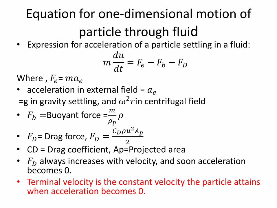
Equation for one-dimensional motion of
particle through fluid• Expression for acceleration of a particle settling in a fluid:
𝑚𝑑𝑢
𝑑𝑡= 𝐹𝑒 − 𝐹𝑏 − 𝐹𝐷
Where , 𝐹𝑒= 𝑚𝑎𝑒• acceleration in external field = 𝑎𝑒=g in gravity settling, and ω2𝑟in centrifugal field
• 𝐹𝑏 =Buoyant force =𝑚
𝜌𝑝𝜌
• 𝐹𝐷= Drag force, 𝐹𝐷 =𝐶𝐷𝜌𝑢
2𝐴𝑝
2• CD = Drag coefficient, Ap=Projected area• 𝐹𝐷 always increases with velocity, and soon acceleration
becomes 0.• Terminal velocity is the constant velocity the particle attains
when acceleration becomes 0.
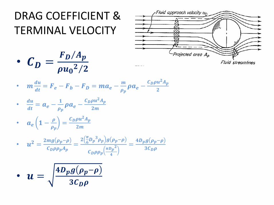
DRAG COEFFICIENT &TERMINAL VELOCITY
• 𝑪𝑫 = 𝑭𝑫 𝑨𝒑
𝝆𝒖𝟎𝟐 𝟐
• 𝒎𝒅𝒖
𝒅𝒕= 𝑭𝒆 − 𝑭𝒃 − 𝑭𝑫 = 𝒎𝒂𝒆 −
𝒎
𝝆𝒑𝝆𝒂𝒆 −
𝑪𝑫𝝆𝒖𝟐𝑨𝒑
𝟐
•𝒅𝒖
𝒅𝒕= 𝒂𝒆 −
𝟏
𝝆𝒑𝝆𝒂𝒆 −
𝑪𝑫𝝆𝒖𝟐𝑨𝒑
𝟐𝒎
• 𝒂𝒆 𝟏 −𝝆
𝝆𝒑=𝑪𝑫𝝆𝒖
𝟐𝑨𝒑
𝟐𝒎
• 𝒖𝟐 =𝟐𝒎𝒈 𝝆𝒑−𝝆
𝑪𝑫𝝆𝝆𝒑𝑨𝒑=𝟐𝝅
𝟔𝑫𝒑𝟑𝝆𝒑 𝒈 𝝆𝒑−𝝆
𝑪𝑫𝝆𝝆𝒑𝝅𝑫𝒑𝟐
𝟒
=𝟒𝑫𝒑𝒈 𝝆𝒑−𝝆
𝟑𝑪𝑫𝝆
• 𝒖 =𝟒𝑫𝒑𝒈 𝝆𝒑−𝝆
𝟑𝑪𝑫𝝆
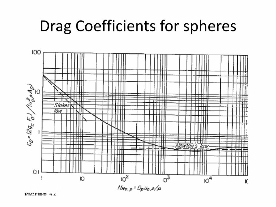
Drag Coefficients for spheres
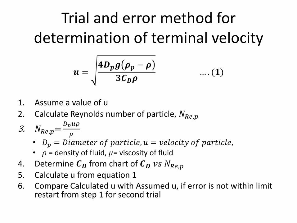
Trial and error method for determination of terminal velocity
𝒖 =𝟒𝑫𝒑𝒈 𝝆𝒑 − 𝝆
𝟑𝑪𝑫𝝆… . (𝟏)
1. Assume a value of u
2. Calculate Reynolds number of particle, 𝑁𝑅𝑒,𝑝
3. 𝑁𝑅𝑒,𝑝=𝐷𝑝𝑢𝜌
𝜇
• 𝐷𝑝 = 𝐷𝑖𝑎𝑚𝑒𝑡𝑒𝑟 𝑜𝑓 𝑝𝑎𝑟𝑡𝑖𝑐𝑙𝑒, 𝑢 = 𝑣𝑒𝑙𝑜𝑐𝑖𝑡𝑦 𝑜𝑓 𝑝𝑎𝑟𝑡𝑖𝑐𝑙𝑒,• 𝜌 = density of fluid, 𝜇= viscosity of fluid
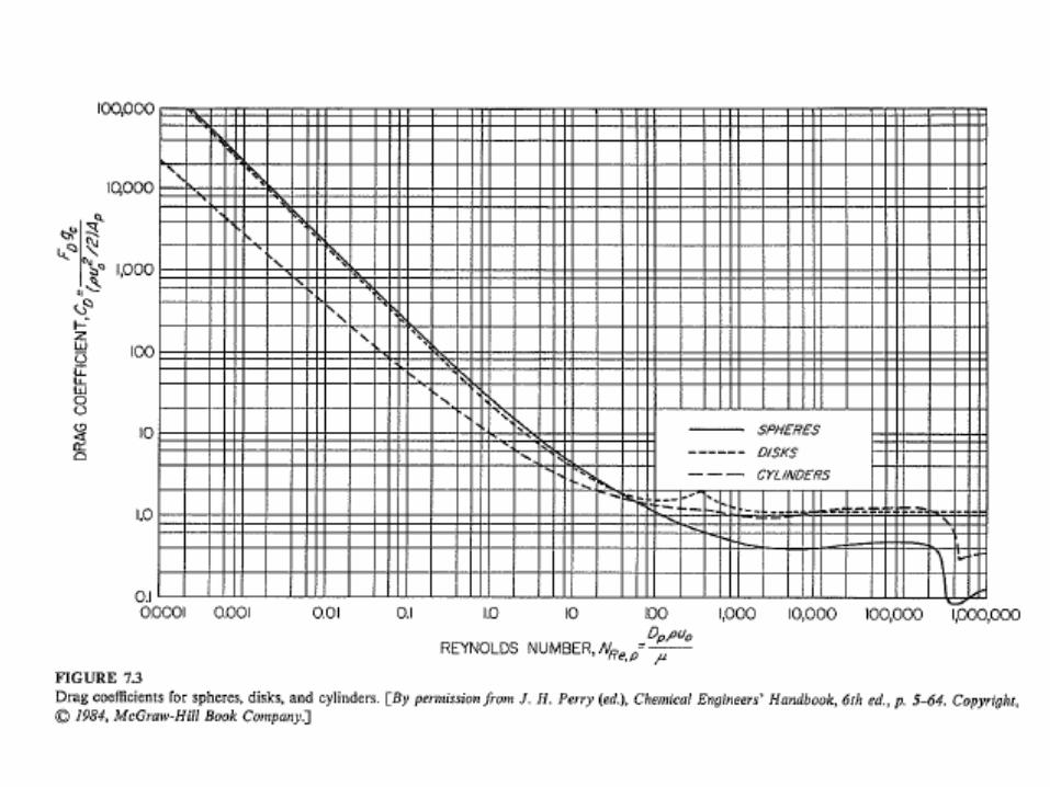
4. Determine 𝑪𝑫 from chart of 𝑪𝑫 𝑣𝑠 𝑁𝑅𝑒,𝑝5. Calculate u from equation 16. Compare Calculated u with Assumed u, if error is not within limit
restart from step 1 for second trial
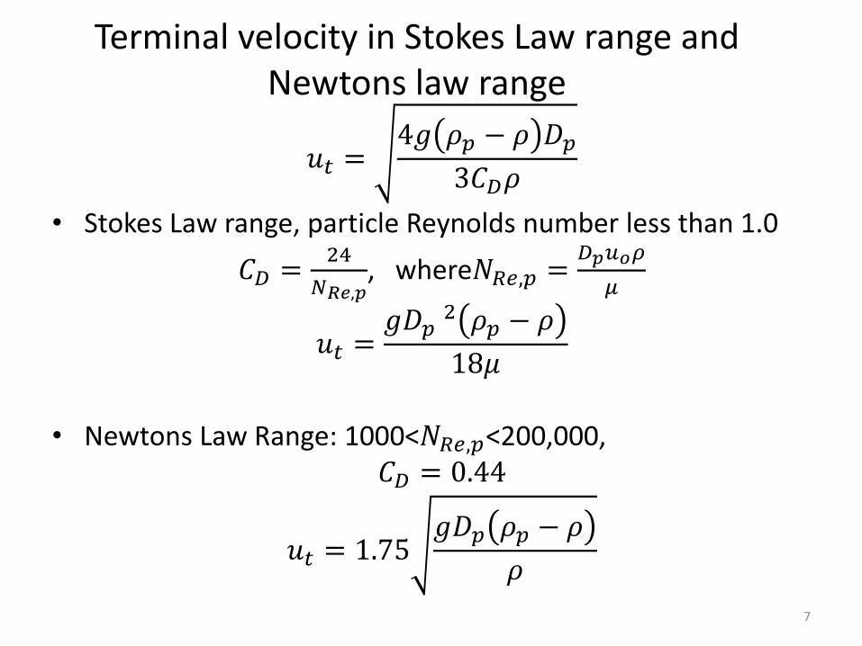
Terminal velocity in Stokes Law range and Newtons law range
𝑢𝑡 =4𝑔 𝜌𝑝 − 𝜌 𝐷𝑝
3𝐶𝐷𝜌
• Stokes Law range, particle Reynolds number less than 1.0
𝐶𝐷 =24
𝑁𝑅𝑒,𝑝, where𝑁𝑅𝑒,𝑝 =
𝐷𝑝𝑢𝑜𝜌
𝜇
𝑢𝑡 =𝑔𝐷𝑝
2 𝜌𝑝 − 𝜌
18𝜇
• Newtons Law Range: 1000<𝑁𝑅𝑒,𝑝<200,000, 𝐶𝐷 = 0.44
𝑢𝑡 = 1.75𝑔𝐷𝑝 𝜌𝑝 − 𝜌
𝜌
7
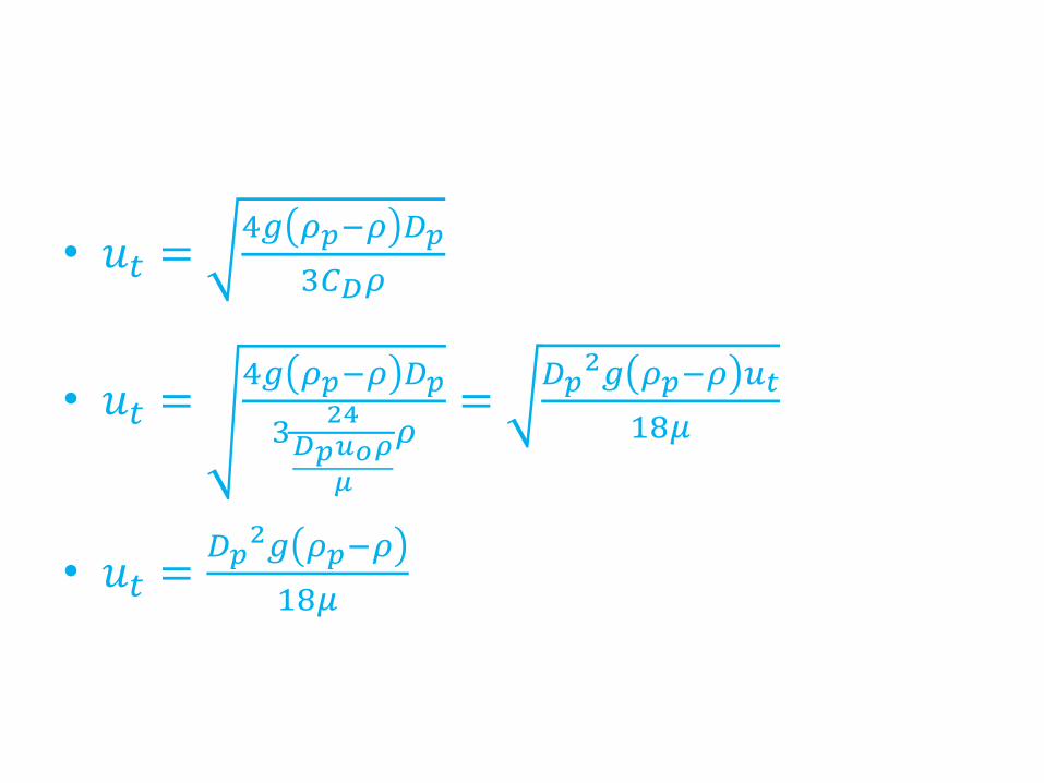
• 𝑢𝑡 =4𝑔 𝜌𝑝−𝜌 𝐷𝑝
3𝐶𝐷𝜌
• 𝑢𝑡 =4𝑔 𝜌𝑝−𝜌 𝐷𝑝
324𝐷𝑝𝑢𝑜𝜌
𝜇
𝜌=𝐷𝑝2𝑔 𝜌𝑝−𝜌 𝑢𝑡
18𝜇
• 𝑢𝑡 =𝐷𝑝2𝑔 𝜌𝑝−𝜌
18𝜇
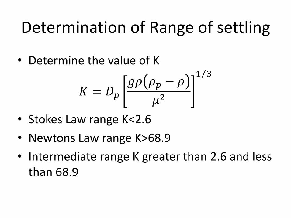
Determination of Range of settling
• Determine the value of K
𝐾 = 𝐷𝑝𝑔𝜌 𝜌𝑝 − 𝜌
𝜇2
1 3
• Stokes Law range K<2.6
• Newtons Law range K>68.9
• Intermediate range K greater than 2.6 and less than 68.9
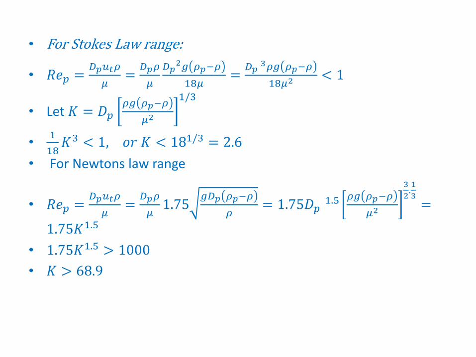
• For Stokes Law range:
• 𝑅𝑒𝑝 =𝐷𝑝𝑢𝑡𝜌
𝜇=𝐷𝑝𝜌
𝜇
𝐷𝑝2𝑔 𝜌𝑝−𝜌
18𝜇=𝐷𝑝3𝜌𝑔 𝜌𝑝−𝜌
18𝜇2< 1
• Let 𝐾 = 𝐷𝑝𝜌𝑔 𝜌𝑝−𝜌
𝜇2
1/3
•1
18𝐾3 < 1, 𝑜𝑟 𝐾 < 181/3 = 2.6
• For Newtons law range
• 𝑅𝑒𝑝 =𝐷𝑝𝑢𝑡𝜌
𝜇=𝐷𝑝𝜌
𝜇1.75
𝑔𝐷𝑝 𝜌𝑝−𝜌
𝜌= 1.75𝐷𝑝
1.5 𝜌𝑔 𝜌𝑝−𝜌
𝜇2
3
2.1
3=
1.75𝐾1.5
• 1.75𝐾1.5 > 1000
• 𝐾 > 68.9
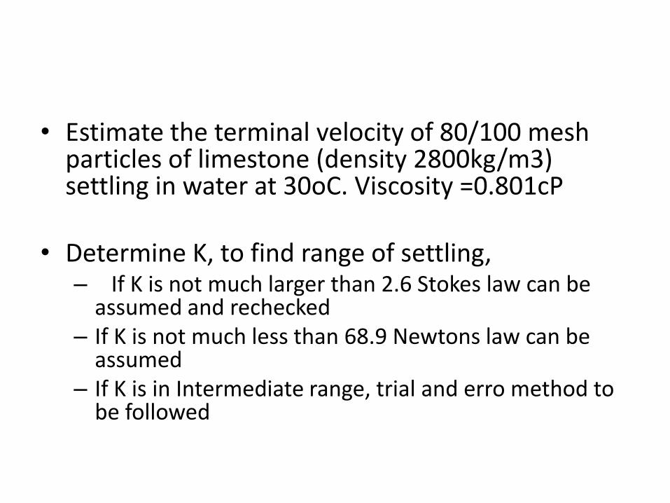
• Estimate the terminal velocity of 80/100 mesh particles of limestone (density 2800kg/m3) settling in water at 30oC. Viscosity =0.801cP
• Determine K, to find range of settling,– If K is not much larger than 2.6 Stokes law can be
assumed and rechecked– If K is not much less than 68.9 Newtons law can be
assumed– If K is in Intermediate range, trial and erro method to
be followed
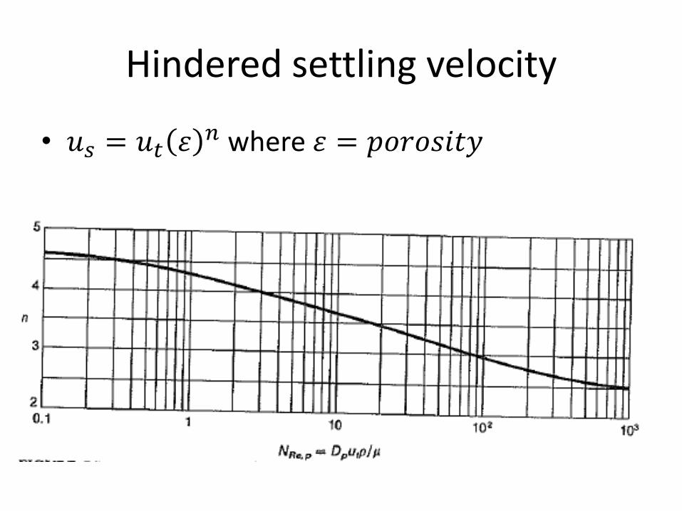
Hindered settling velocity
• 𝑢𝑠 = 𝑢𝑡 𝜀𝑛 where 𝜀 = 𝑝𝑜𝑟𝑜𝑠𝑖𝑡𝑦
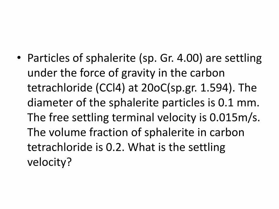
• Particles of sphalerite (sp. Gr. 4.00) are settling under the force of gravity in the carbon tetrachloride (CCl4) at 20oC(sp.gr. 1.594). The diameter of the sphalerite particles is 0.1 mm. The free settling terminal velocity is 0.015m/s. The volume fraction of sphalerite in carbon tetrachloride is 0.2. What is the settling velocity?
Solid Liquid SeparationSettling – Gravity and Centrifugal
Reference McCabe Smith
14
GRAVITY SETTLING
15
16
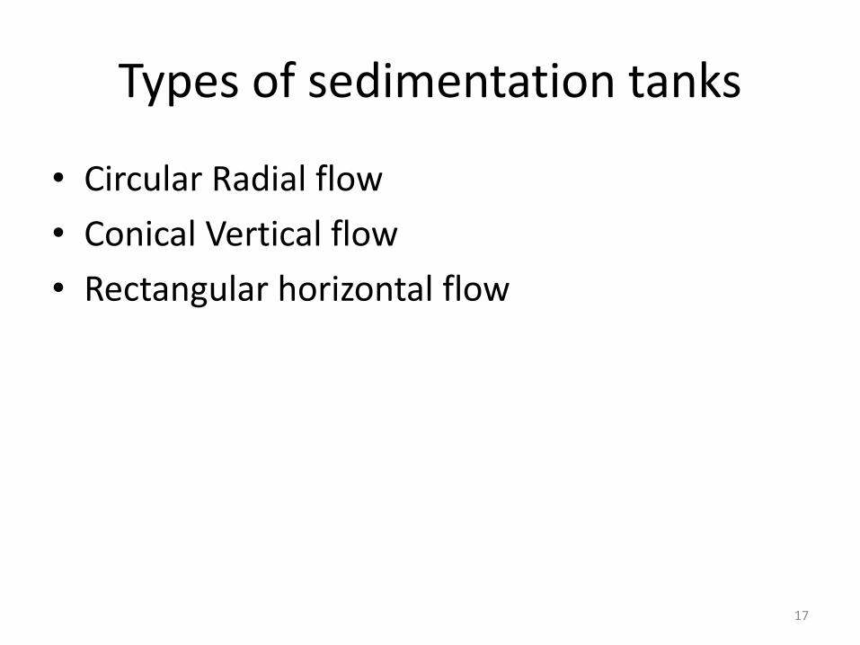
Types of sedimentation tanks
• Circular Radial flow
• Conical Vertical flow
• Rectangular horizontal flow
17
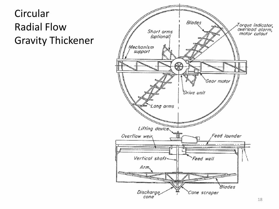
Circular Radial FlowGravity Thickener
18
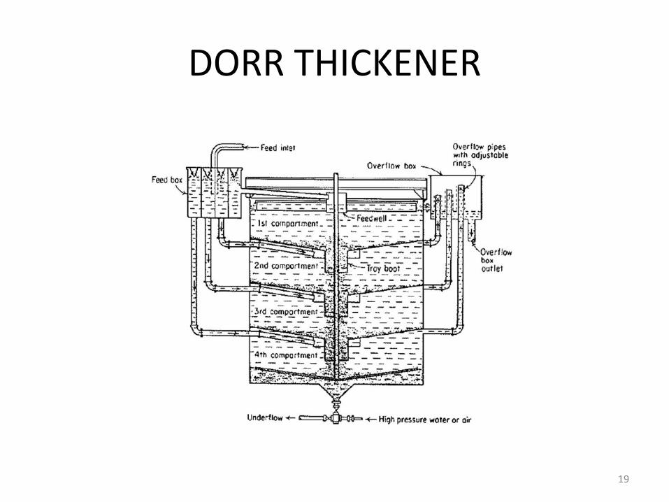
DORR THICKENER
19
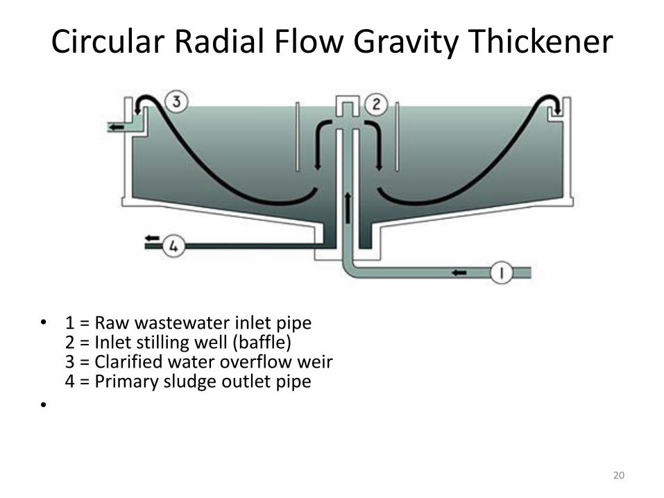
Circular Radial Flow Gravity Thickener
• 1 = Raw wastewater inlet pipe2 = Inlet stilling well (baffle)3 = Clarified water overflow weir4 = Primary sludge outlet pipe
•
20
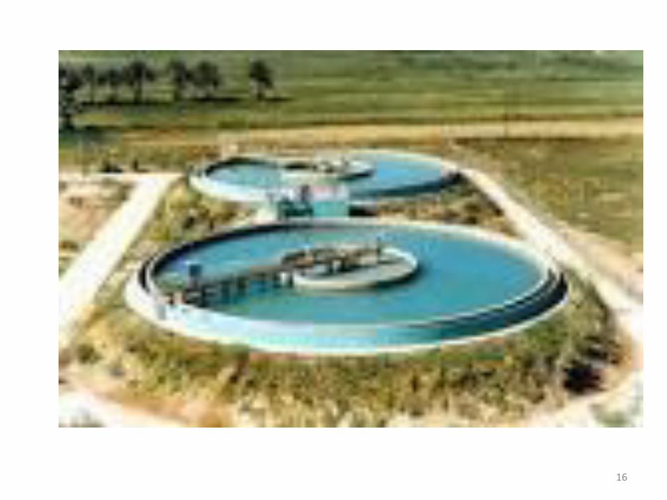
• After the removal of inorganic screenings and grit, the next step in wastewater treatment is the removal of the grosser suspended solids from the raw sewage. This is achieved via the process of primary settling or primary sedimentation. The wastewater flow is directed into one or more settling tanks, also known as primary clarifiers. Large mechanically-raked circular tanks are generally used at the larger works,.
• The overall volume of the primary settling tank is designed to ensure the incoming wastewater will take a certain amount of time to flow completely through the structure. This is known as the retention time, and must be sufficiently long enough to allow suitable settling of the solids to take place, yet short enough to prevent the anaerobic breakdown of the settled solids from occurring (i.e. the settled sludge turning septic).
• The retention time can vary from 1 to 3 hours, depending on the plant loading and incoming wastewater characteristics. In a tank with a retention time of 2 hours, 50 to 70% of the suspended solids may be removed by settling and flotation (scum removal). Removal of these solids will also reduce the BOD by 30 to 35%.
• Of equal importance in the design of the primary settling tank is the surface loading rate. This will dictate the overall diameter of a circular settling tank. This is effectively the upward velocity of the incoming flow from the base of the tank to the top of the overflow weirs. Upflowvelocities of around 1.0m per hour are generally desired.
21
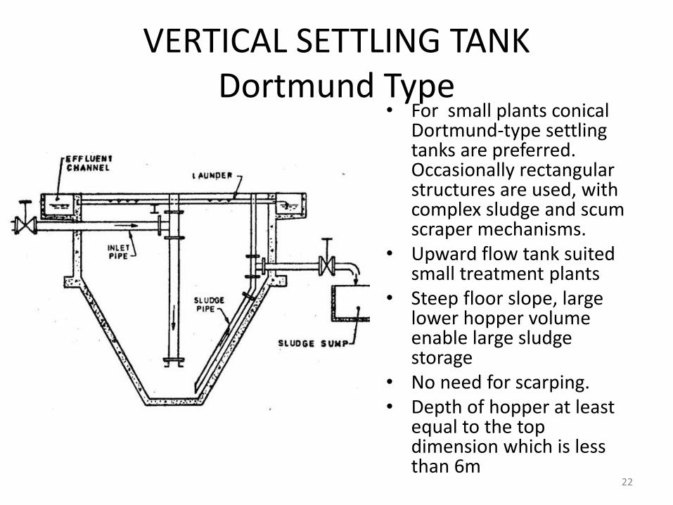
VERTICAL SETTLING TANKDortmund Type
• For small plants conical Dortmund-type settling tanks are preferred. Occasionally rectangular structures are used, with complex sludge and scum scraper mechanisms.
• Upward flow tank suited small treatment plants
• Steep floor slope, large lower hopper volume enable large sludge storage
• No need for scarping.• Depth of hopper at least
equal to the top dimension which is less than 6m
22
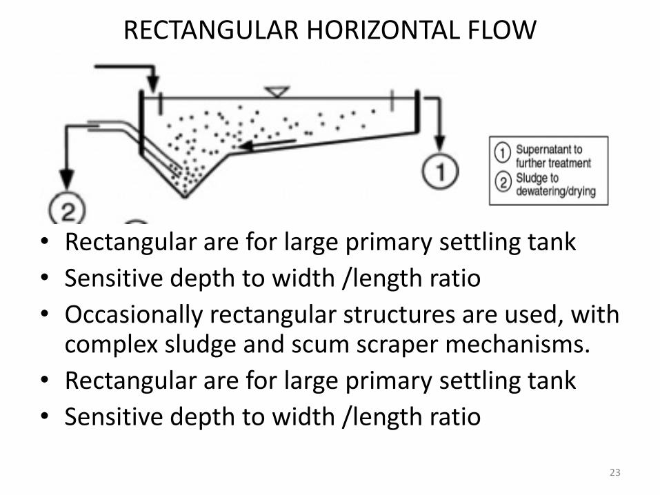
RECTANGULAR HORIZONTAL FLOW
• .
• Rectangular are for large primary settling tank
• Sensitive depth to width /length ratio
• Occasionally rectangular structures are used, with complex sludge and scum scraper mechanisms.
• Rectangular are for large primary settling tank
• Sensitive depth to width /length ratio
23
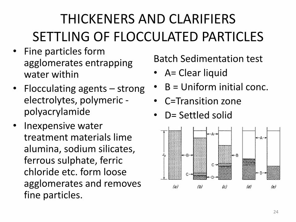
THICKENERS AND CLARIFIERSSETTLING OF FLOCCULATED PARTICLES
• Fine particles form agglomerates entrapping water within
• Flocculating agents – strong electrolytes, polymeric -polyacrylamide
• Inexpensive water treatment materials lime alumina, sodium silicates, ferrous sulphate, ferric chloride etc. form loose agglomerates and removes fine particles.
Batch Sedimentation test
• A= Clear liquid
• B = Uniform initial conc.
• C=Transition zone
• D= Settled solid
24
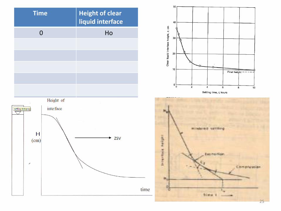
Time Height of clear liquid interface
0 Ho
25
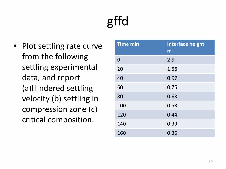
gffd
• Plot settling rate curve from the following settling experimental data, and report (a)Hindered settling velocity (b) settling in compression zone (c) critical composition.
Time min Interface height m
0 2.5
20 1.56
40 0.97
60 0.75
80 0.63
100 0.53
120 0.44
140 0.39
160 0.36
26
SETTLING TANK DESIGNRef: McCabe Smith
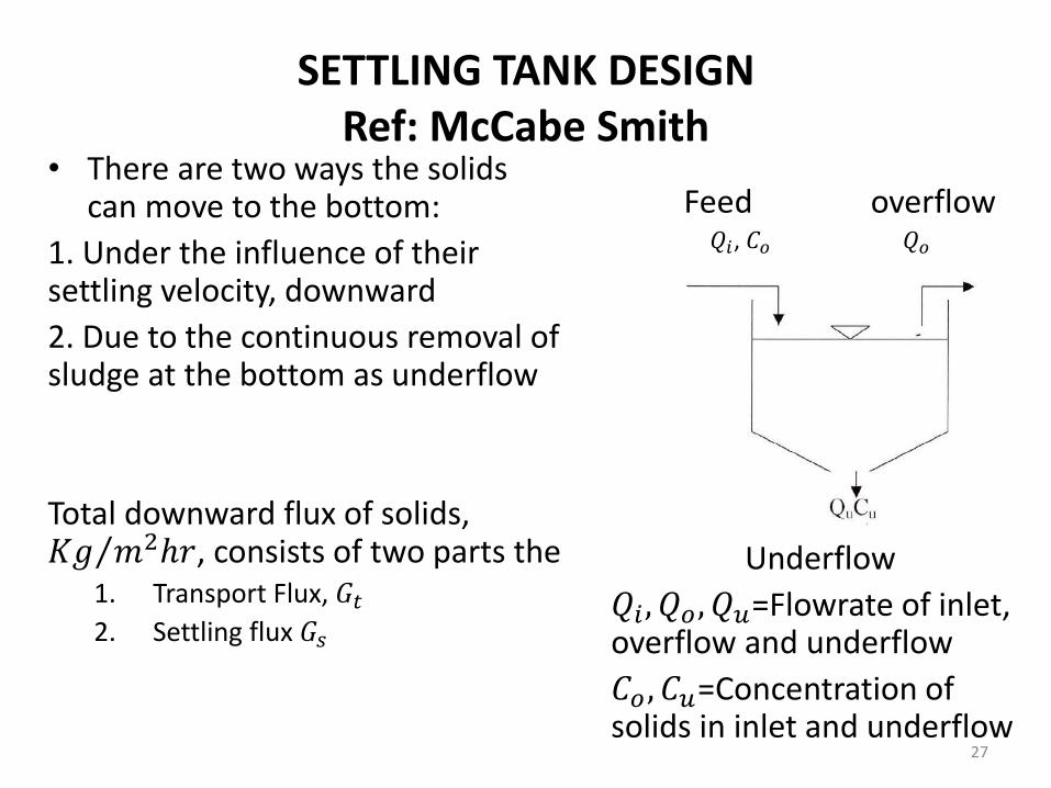
• There are two ways the solids can move to the bottom:
1. Under the influence of their settling velocity, downward
2. Due to the continuous removal of sludge at the bottom as underflow
Total downward flux of solids, 𝐾𝑔 𝑚2ℎ𝑟, consists of two parts the 1. Transport Flux, 𝐺𝑡2. Settling flux 𝐺𝑠
Feed overflow𝑄𝑖, 𝐶𝑜 𝑄𝑜
Underflow
𝑄𝑖 , 𝑄𝑜, 𝑄𝑢=Flowrate of inlet, overflow and underflow
𝐶𝑜 , 𝐶𝑢=Concentration of solids in inlet and underflow
27
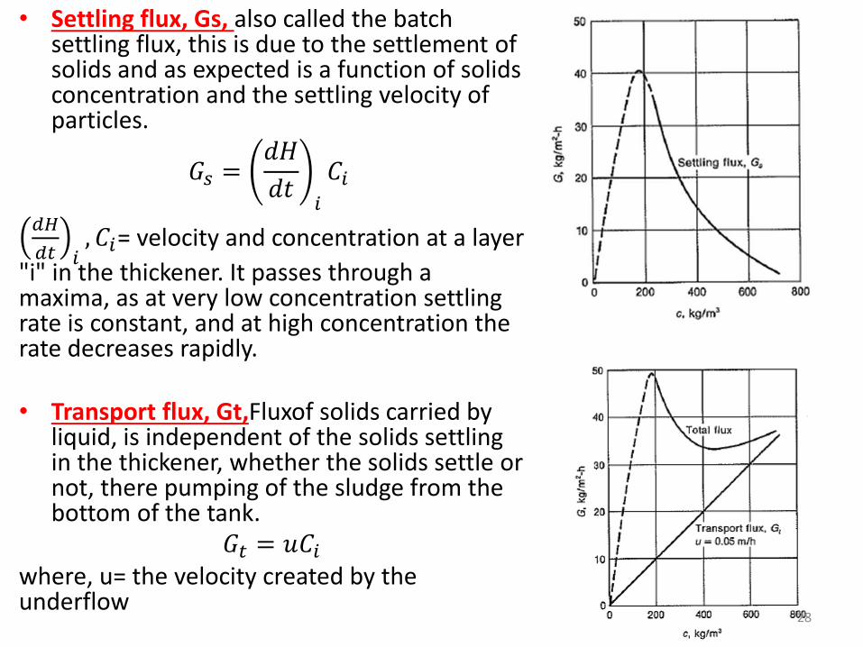
• Settling flux, Gs, also called the batch settling flux, this is due to the settlement of solids and as expected is a function of solids concentration and the settling velocity of particles.
𝐺𝑠 =𝑑𝐻
𝑑𝑡𝑖
𝐶𝑖
𝑑𝐻
𝑑𝑡 𝑖, 𝐶𝑖= velocity and concentration at a layer
"i" in the thickener. It passes through a maxima, as at very low concentration settling rate is constant, and at high concentration the rate decreases rapidly.
• Transport flux, Gt,Fluxof solids carried by liquid, is independent of the solids settling in the thickener, whether the solids settle or not, there pumping of the sludge from the bottom of the tank.
𝐺𝑡 = 𝑢𝐶𝑖where, u= the velocity created by the underflow
28
SETTLING TANKAREA
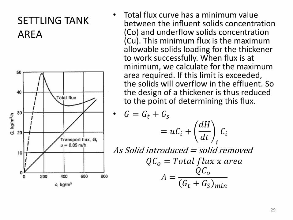
• Total flux curve has a minimum value between the influent solids concentration (Co) and underflow solids concentration (Cu). This minimum flux is the maximum allowable solids loading for the thickener to work successfully. When flux is at minimum, we calculate for the maximum area required. If this limit is exceeded, the solids will overflow in the effluent. So the design of a thickener is thus reduced to the point of determining this flux.
• 𝐺 = 𝐺𝑡 + 𝐺𝑠
= 𝑢𝐶𝑖 +𝑑𝐻
𝑑𝑡𝑖
𝐶𝑖
As Solid introduced = solid removed𝑄𝐶𝑜 = 𝑇𝑜𝑡𝑎𝑙 𝑓𝑙𝑢𝑥 𝑥 𝑎𝑟𝑒𝑎
𝐴 =𝑄𝐶𝑜
𝐺𝑡 + 𝐺𝑆 𝑚𝑖𝑛
29
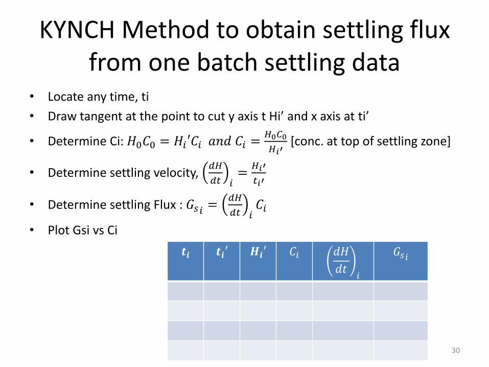
KYNCH Method to obtain settling flux from one batch settling data
• Locate any time, ti
• Draw tangent at the point to cut y axis t Hi’ and x axis at ti’
• Determine Ci: 𝐻0𝐶0 = 𝐻𝑖′𝐶𝑖 𝑎𝑛𝑑 𝐶𝑖 =𝐻0𝐶0
𝐻𝑖′[conc. at top of settling zone]
• Determine settling velocity, 𝑑𝐻
𝑑𝑡 𝑖=𝐻𝑖′
𝑡𝑖′
• Determine settling Flux : 𝐺𝑠𝑖 =𝑑𝐻
𝑑𝑡 𝑖𝐶𝑖
• Plot Gsi vs Ci
𝒕𝒊 𝒕𝒊′ 𝑯𝒊′ 𝐶𝑖 𝑑𝐻
𝑑𝑡𝑖
𝐺𝑠𝑖
30
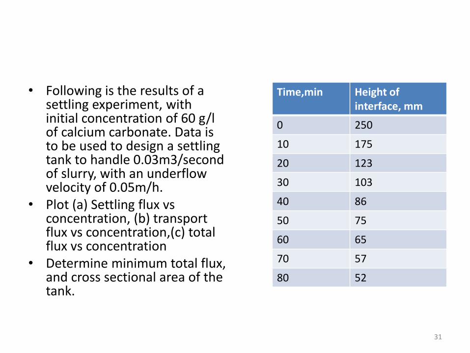
• Following is the results of a settling experiment, with initial concentration of 60 g/l of calcium carbonate. Data is to be used to design a settling tank to handle 0.03m3/second of slurry, with an underflow velocity of 0.05m/h.
• Plot (a) Settling flux vs concentration, (b) transport flux vs concentration,(c) total flux vs concentration
• Determine minimum total flux, and cross sectional area of the tank.
Time,min Height of interface, mm
0 250
10 175
20 123
30 103
40 86
50 75
60 65
70 57
80 52
31

CENTRIFUGAL SETTLING
32
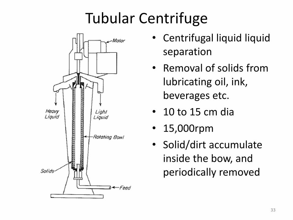
Tubular Centrifuge • Centrifugal liquid liquid
separation
• Removal of solids from lubricating oil, ink, beverages etc.
• 10 to 15 cm dia
• 15,000rpm
• Solid/dirt accumulate inside the bow, and periodically removed
33
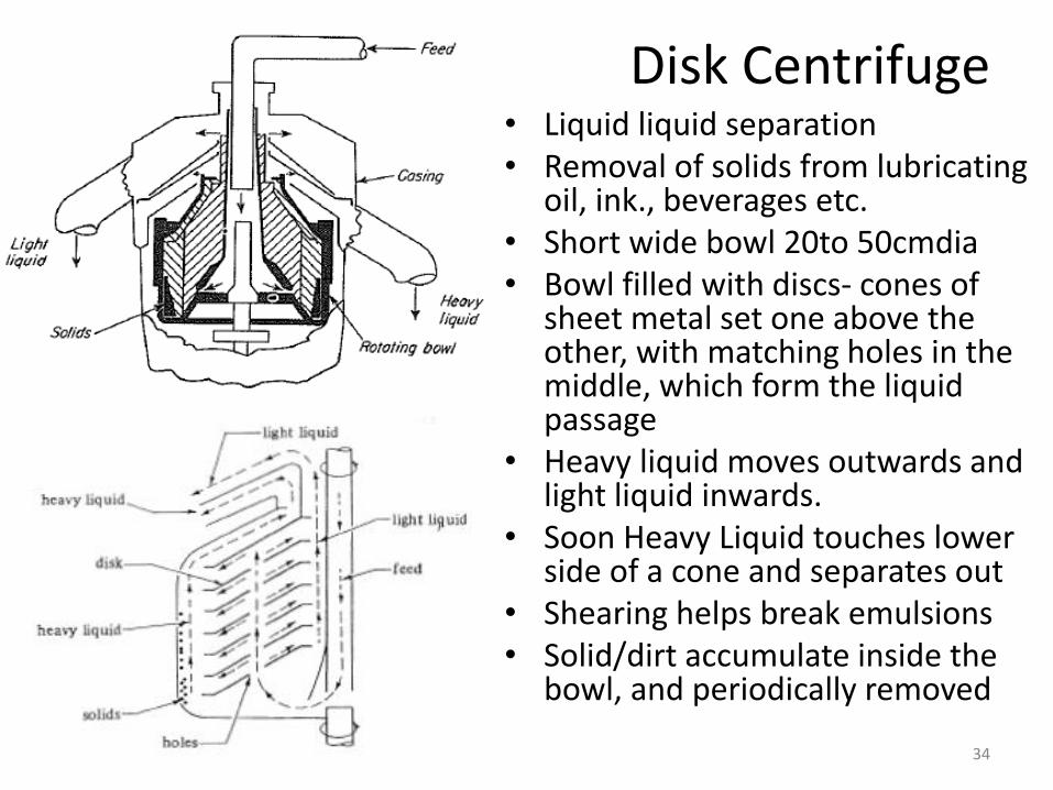
Disk Centrifuge• Liquid liquid separation• Removal of solids from lubricating
oil, ink., beverages etc.• Short wide bowl 20to 50cmdia• Bowl filled with discs- cones of
sheet metal set one above the other, with matching holes in the middle, which form the liquid passage
• Heavy liquid moves outwards and light liquid inwards.
• Soon Heavy Liquid touches lower side of a cone and separates out
• Shearing helps break emulsions • Solid/dirt accumulate inside the
bowl, and periodically removed
34
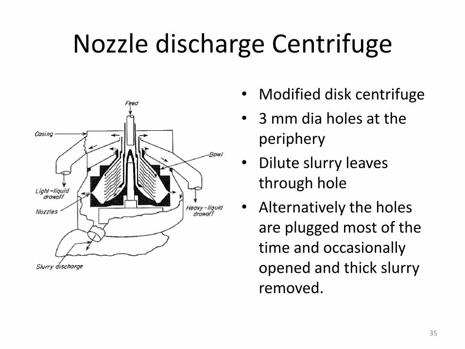
Nozzle discharge Centrifuge
• Modified disk centrifuge
• 3 mm dia holes at the periphery
• Dilute slurry leaves through hole
• Alternatively the holes are plugged most of the time and occasionally opened and thick slurry removed.
35
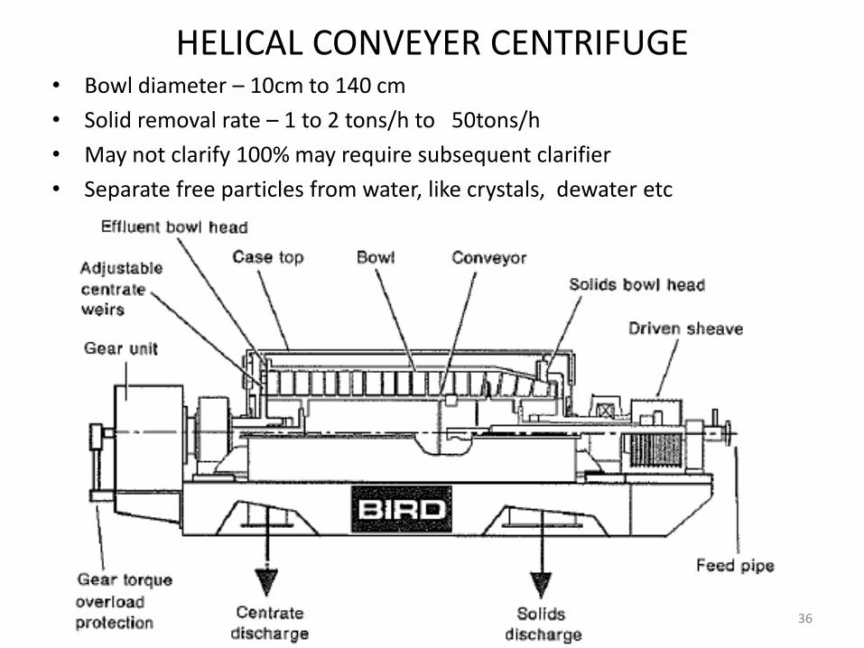
HELICAL CONVEYER CENTRIFUGE• Bowl diameter – 10cm to 140 cm
• Solid removal rate – 1 to 2 tons/h to 50tons/h
• May not clarify 100% may require subsequent clarifier
• Separate free particles from water, like crystals, dewater etc
36
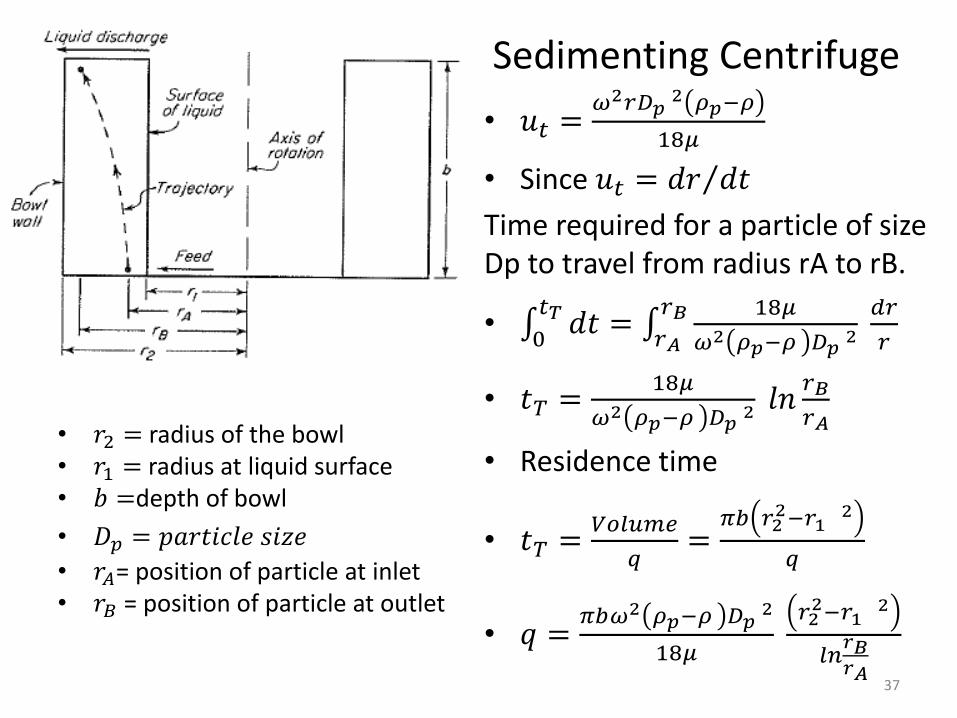
Sedimenting Centrifuge
• 𝑟2 = radius of the bowl• 𝑟1 = radius at liquid surface• 𝑏 =depth of bowl
• 𝐷𝑝 = 𝑝𝑎𝑟𝑡𝑖𝑐𝑙𝑒 𝑠𝑖𝑧𝑒
• 𝑟𝐴= position of particle at inlet• 𝑟𝐵 = position of particle at outlet
• 𝑢𝑡 =𝜔2𝑟𝐷𝑝
2 𝜌𝑝−𝜌
18𝜇
• Since 𝑢𝑡 = 𝑑𝑟 𝑑𝑡
Time required for a particle of size Dp to travel from radius rA to rB.
• 0𝑡𝑇 𝑑𝑡 = 𝑟𝐴
𝑟𝐵 18𝜇
𝜔2 𝜌𝑝−𝜌 𝐷𝑝2
𝑑𝑟
𝑟
• 𝑡𝑇 =18𝜇
𝜔2 𝜌𝑝−𝜌 𝐷𝑝2 𝑙𝑛𝑟𝐵
𝑟𝐴
• Residence time
• 𝑡𝑇 =𝑉𝑜𝑙𝑢𝑚𝑒
𝑞=𝜋𝑏 𝑟2
2−𝑟12
𝑞
• 𝑞 =𝜋𝑏𝜔2 𝜌𝑝−𝜌 𝐷𝑝
2
18𝜇
𝑟22−𝑟1
2
𝑙𝑛𝑟𝐵𝑟𝐴
37
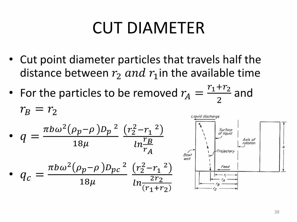
CUT DIAMETER
• Cut point diameter particles that travels half the distance between 𝑟2 𝑎𝑛𝑑 𝑟1in the available time
• For the particles to be removed 𝑟𝐴 =𝑟1+𝑟2
2and
𝑟𝐵 = 𝑟2
• 𝑞 =𝜋𝑏𝜔2 𝜌𝑝−𝜌 𝐷𝑝
2
18𝜇
𝑟22−𝑟1
2
𝑙𝑛𝑟𝐵𝑟𝐴
• 𝑞𝑐 =𝜋𝑏𝜔2 𝜌𝑝−𝜌 𝐷𝑝𝑐
2
18𝜇
𝑟22−𝑟1
2
𝑙𝑛2𝑟2𝑟1+𝑟2
38
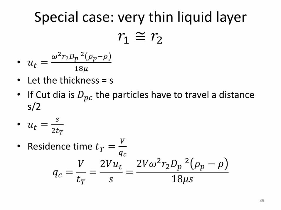
Special case: very thin liquid layer 𝑟1 ≅ 𝑟2
• 𝑢𝑡 =𝜔2𝑟2𝐷𝑝
2 𝜌𝑝−𝜌
18𝜇
• Let the thickness = s
• If Cut dia is 𝐷𝑝𝑐 the particles have to travel a distance s/2
• 𝑢𝑡 =𝑠
2𝑡𝑇
• Residence time 𝑡𝑇 =𝑉
𝑞𝑐
𝑞𝑐 =𝑉
𝑡𝑇=2𝑉𝑢𝑡𝑠=2𝑉𝜔2𝑟2𝐷𝑝
2 𝜌𝑝 − 𝜌
18𝜇𝑠
39
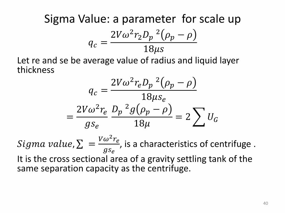
Sigma Value: a parameter for scale up
𝑞𝑐 =2𝑉𝜔2𝑟2𝐷𝑝
2 𝜌𝑝 − 𝜌
18𝜇𝑠Let re and se be average value of radius and liquid layer thickness
𝑞𝑐 =2𝑉𝜔2𝑟𝑒𝐷𝑝
2 𝜌𝑝 − 𝜌
18𝜇𝑠𝑒
=2𝑉𝜔2𝑟𝑒𝑔𝑠𝑒
𝐷𝑝2𝑔 𝜌𝑝 − 𝜌
18𝜇= 2 𝑈𝐺
𝑆𝑖𝑔𝑚𝑎 𝑣𝑎𝑙𝑢𝑒, =𝑉𝜔2𝑟𝑒
𝑔𝑠𝑒, is a characteristics of centrifuge .
It is the cross sectional area of a gravity settling tank of the same separation capacity as the centrifuge.
40
41
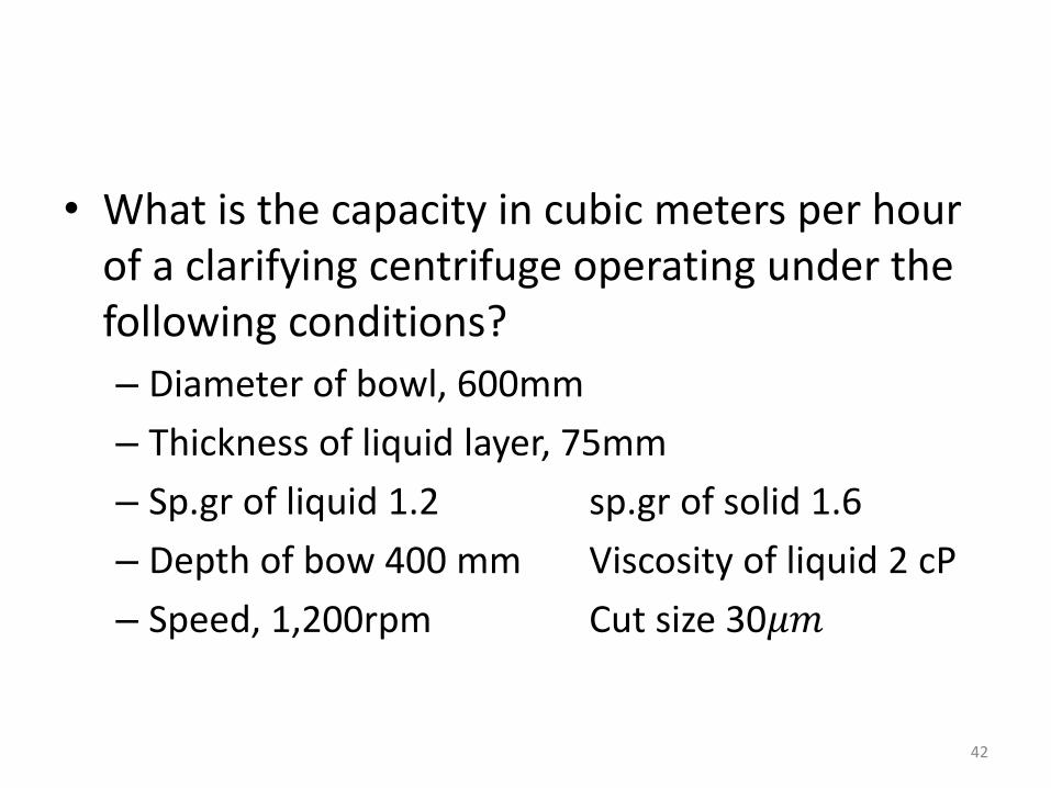
• What is the capacity in cubic meters per hour of a clarifying centrifuge operating under the following conditions?
– Diameter of bowl, 600mm
– Thickness of liquid layer, 75mm
– Sp.gr of liquid 1.2 sp.gr of solid 1.6
– Depth of bow 400 mm Viscosity of liquid 2 cP
– Speed, 1,200rpm Cut size 30𝜇𝑚
42