Poly(meth)acrylate-PVDF core–shell particles from emulsion ...
11
Polymer Chemistry PAPER Cite this: Polym. Chem., 2018, 9, 5359 Received 22nd August 2018, Accepted 16th October 2018 DOI: 10.1039/c8py01236a rsc.li/polymers Poly(meth)acrylate-PVDF core–shell particles from emulsion polymerization: preferential formation of the PVDF β crystal phase† Florian Brandl, a Andreas F. Thünemann b and Sabine Beuermann * a A facile and convenient approach for the synthesis of core–shell particles via emulsion polymerization is presented. The shell consists of poly(vinylidene fluoride) (PVDF) and the core of poly(methyl methacrylate) (PMMA), poly(glycidyl methacrylate) (PGMA) or poly(methyl acrylate) (PMA). In a first step, a non-fluori- nated (meth)acrylate monomer is polymerized in the emulsion to produce poly(meth)acrylate core par- ticles. Secondly, vinylidene fluoride (VDF) is directly added to the reactor and polymerized for shell for- mation. Small-angle X-ray scattering (SAXS) was employed to characterize the structure of the core–shell particles. Interestingly, the particles’ core contains fluorinated and non-fluorinated polymers, whereas the shell of the particles consists only of PVDF. The resulting particles with a diameter of around 40 nm show a significantly higher PVDF β phase content than the PVDF homopolymer obtained by emulsion polymerization. Introduction Poly(vinylidene fluoride) (PVDF) is a thermoplastic fluoropoly- mer, which shows extraordinary properties like thermal stabi- lity, chemical inertness, resistance to acids, and low flamm- ability. 1 PVDF is used in the chemical and automotive indus- tries as well as in electric, medical, and other high-tech appli- cations. 2 Due to its ferro-, piezo-, and pyroelectric properties, PVDF is attractive for sensors and switches. 3–5 These electro- active properties are associated with the all-trans conformation of the PVDF β crystalline phase, which is one of five PVDF crys- talline phases (α, β, γ, δ, and ε). 6,7 Most frequently PVDF shows α phase crystallinity. Several processes, e.g., such as mechani- cal stretching of the α polymorph, melting under high pressure, ultrafast cooling, solvent casting, and addition of fillers, were reported to yield β phase PVDF. 4,8–11 Moreover, blends of PVDF and poly(methyl methacrylate) (PMMA) as well as block copolymers of PVDF with PMMA or other fluoro- polymers may yield β phase PVDF. 12–15 Recently, the complex interactions between PVDF and PMMA in polymer blends were studied in detail. 16–19 Moreover, the interactions in systems consisting of a PVDF core and a PMMA shell in the form of Janus particles were addressed. 20,21 Pan et al. investigated systems with a PVDF core. 21,22 Apart from these publications, reports on core–shell architectures with PVDF are scarce. 23,24 Moreover, the intro- duction of particulate materials into a PVDF matrix 25–27 to impact the crystallinity and the electroactive properties was studied. 28,29 Based on reports that in particular the presence of PMMA either in blends or block copolymers with PVDF is favorable for the formation of β phase PVDF, it appeared interesting to investigate the crystallinity, if a PMMA or more general a poly (meth)acrylate core is covered with a PVDF shell. It was specu- lated that such a core–shell structure with PVDF as the shell may influence the morphology and may affect the amount of β phase material. Due to expected favorable interactions between fluorine atoms in PVDF and the carbonyl groups in poly((meth) acrylates), a directive force may be expected to occur. 30 Thus, the concept of affecting the crystallinity of PVDF in core–shell systems appeared very attractive to investigate. Generally, for the preparation of core–shell particles (CSPs), techniques such as emulsion, dispersion, and precipitation polymerization were applied. 31 The synthetic routes encom- pass several process steps. Examples are two stage emulsion polymerization, CSP formation in the emulsion by using reac- tive surfactants, stepwise hetero-coagulation of smaller cat- ionic polymer particles onto larger anionic polymer particles, and self-aggregation of block copolymers. In this contribution, a rather facile synthetic route is introduced. Firstly, a PMMA † Electronic supplementary information (ESI) available. See DOI: 10.1039/ c8py01236a a Clausthal University of Technology, Institute of Technical Chemistry, Arnold-Sommerfeld-Straße 4, 38678 Clausthal-Zellerfeld, Germany. E-mail: [email protected] b Federal Institute for Materials Research and Testing (BAM), Unter den Eichen 87, 12205 Berlin, Germany This journal is © The Royal Society of Chemistry 2018 Polym. Chem. , 2018, 9, 5359–5369 | 5359 Open Access Article. Published on 17 October 2018. Downloaded on 3/14/2022 8:58:24 AM. This article is licensed under a Creative Commons Attribution-NonCommercial 3.0 Unported Licence. View Article Online View Journal | View Issue
Transcript of Poly(meth)acrylate-PVDF core–shell particles from emulsion ...
PolymerChemistry
PAPER
Cite this: Polym. Chem., 2018, 9,5359
Received 22nd August 2018,Accepted 16th October 2018
DOI: 10.1039/c8py01236a
rsc.li/polymers
Poly(meth)acrylate-PVDF core–shell particles fromemulsion polymerization: preferential formation ofthe PVDF β crystal phase†
Florian Brandl,a Andreas F. Thünemann b and Sabine Beuermann *a
A facile and convenient approach for the synthesis of core–shell particles via emulsion polymerization is
presented. The shell consists of poly(vinylidene fluoride) (PVDF) and the core of poly(methyl methacrylate)
(PMMA), poly(glycidyl methacrylate) (PGMA) or poly(methyl acrylate) (PMA). In a first step, a non-fluori-
nated (meth)acrylate monomer is polymerized in the emulsion to produce poly(meth)acrylate core par-
ticles. Secondly, vinylidene fluoride (VDF) is directly added to the reactor and polymerized for shell for-
mation. Small-angle X-ray scattering (SAXS) was employed to characterize the structure of the core–shell
particles. Interestingly, the particles’ core contains fluorinated and non-fluorinated polymers, whereas the
shell of the particles consists only of PVDF. The resulting particles with a diameter of around 40 nm show
a significantly higher PVDF β phase content than the PVDF homopolymer obtained by emulsion
polymerization.
Introduction
Poly(vinylidene fluoride) (PVDF) is a thermoplastic fluoropoly-mer, which shows extraordinary properties like thermal stabi-lity, chemical inertness, resistance to acids, and low flamm-ability.1 PVDF is used in the chemical and automotive indus-tries as well as in electric, medical, and other high-tech appli-cations.2 Due to its ferro-, piezo-, and pyroelectric properties,PVDF is attractive for sensors and switches.3–5 These electro-active properties are associated with the all-trans conformationof the PVDF β crystalline phase, which is one of five PVDF crys-talline phases (α, β, γ, δ, and ε).6,7 Most frequently PVDF showsα phase crystallinity. Several processes, e.g., such as mechani-cal stretching of the α polymorph, melting under highpressure, ultrafast cooling, solvent casting, and addition offillers, were reported to yield β phase PVDF.4,8–11 Moreover,blends of PVDF and poly(methyl methacrylate) (PMMA) as wellas block copolymers of PVDF with PMMA or other fluoro-polymers may yield β phase PVDF.12–15
Recently, the complex interactions between PVDF andPMMA in polymer blends were studied in detail.16–19
Moreover, the interactions in systems consisting of a PVDFcore and a PMMA shell in the form of Janus particles wereaddressed.20,21 Pan et al. investigated systems with a PVDFcore.21,22 Apart from these publications, reports on core–shellarchitectures with PVDF are scarce.23,24 Moreover, the intro-duction of particulate materials into a PVDF matrix25–27 toimpact the crystallinity and the electroactive properties wasstudied.28,29
Based on reports that in particular the presence of PMMAeither in blends or block copolymers with PVDF is favorablefor the formation of β phase PVDF, it appeared interesting toinvestigate the crystallinity, if a PMMA or more general a poly(meth)acrylate core is covered with a PVDF shell. It was specu-lated that such a core–shell structure with PVDF as the shellmay influence the morphology and may affect the amount of βphase material. Due to expected favorable interactions betweenfluorine atoms in PVDF and the carbonyl groups in poly((meth)acrylates), a directive force may be expected to occur.30 Thus,the concept of affecting the crystallinity of PVDF in core–shellsystems appeared very attractive to investigate.
Generally, for the preparation of core–shell particles (CSPs),techniques such as emulsion, dispersion, and precipitationpolymerization were applied.31 The synthetic routes encom-pass several process steps. Examples are two stage emulsionpolymerization, CSP formation in the emulsion by using reac-tive surfactants, stepwise hetero-coagulation of smaller cat-ionic polymer particles onto larger anionic polymer particles,and self-aggregation of block copolymers. In this contribution,a rather facile synthetic route is introduced. Firstly, a PMMA
†Electronic supplementary information (ESI) available. See DOI: 10.1039/c8py01236a
aClausthal University of Technology, Institute of Technical Chemistry,
Arnold-Sommerfeld-Straße 4, 38678 Clausthal-Zellerfeld, Germany.
E-mail: [email protected] Institute for Materials Research and Testing (BAM), Unter den Eichen 87,
12205 Berlin, Germany
This journal is © The Royal Society of Chemistry 2018 Polym. Chem., 2018, 9, 5359–5369 | 5359
Ope
n A
cces
s A
rtic
le. P
ublis
hed
on 1
7 O
ctob
er 2
018.
Dow
nloa
ded
on 3
/14/
2022
8:5
8:24
AM
. T
his
artic
le is
lice
nsed
und
er a
Cre
ativ
e C
omm
ons
Attr
ibut
ion-
Non
Com
mer
cial
3.0
Unp
orte
d L
icen
ce.
View Article OnlineView Journal | View Issue
core is obtained by emulsion polymerization. Secondly, afterMMA is fully consumed VDF is added to the reactor to con-tinue with the VDF polymerization. Thus, there is no work-uprequired after the first step. The synthesis of the CSPs isachieved in a single process, which is of course followed bythe work-up of the emulsion. Following this approach,various materials with core–shell architecture with PMMA,poly(glycidyl methacrylate) (PGMA) or poly(methyl acrylate)(PMA) as the core and PVDF as the shell were prepared. Thecore–shell structure was characterized by TEM and SAXS andthe crystallinity was investigated via FTIR and XRD.
Experimental sectionMaterials
Vinylidene fluoride (VDF) and ammonium 4,8-dioxa-3H-per-fluorononanoate (ADONA) were kindly provided by 3 M/Dyneon GmbH and used as received. The monomers methylmethacrylate (MMA, 99% Sigma-Aldrich), glycidyl methacrylate(GMA, ≥97%, Sigma-Aldrich) and methyl acrylate (MA, 99%,Sigma-Aldrich) were distilled under reduced pressure toremove inhibitors. Ammonium persulfate (APS, ≥98% ACROSORGANICS) as the initiator, dimethyl acetamide (DMAc, 99%,ACROS ORGANICS) and LiBr (≥99%, Riedel-de-Häen) servingas the eluent for size-exclusion chromatography were used asreceived. As the reaction medium ultrapure and deionizedwater (electric conductivity: 0.055 µS cm−1) was used.
Polymer characterization
For CSP characterization, the following techniques and equip-ment are used:
Size-exclusion chromatography (SEC) measurements of thecore were carried out in DMAc, which contains 0.1% LiBr asthe eluent at a column temperature of 45 °C. The SEC set-upconsists of an Agilent 1200 isocratic pump, an Agilent 1200refractive index detector, and four PSS GRAM columns (guard,100 Å, 3000 Å, and 3000 Å) from Polymer Standard Service(PSS). Measurements were carried out at a flow rate of1 mL min−1. Polystyrene standards (PSS) of narrow dispersitywere used for calibration.
For FT-IR measurements, a Vertex 70 spectrometer (BrukerOptik GmbH, Bremen, Germany) equipped with a globarsource and a photoacoustic cell (PA301) was used. Spectra wererecorded with a resolution of 4 cm−1 using 20 scans.
Differential scanning calorimetry (DSC) for thermal analysismeasurements was performed with a DSC 1/500658/200 WSTARe system by Mettler Toledo, Columbus, OH, USA. Thissystem is equipped with a FRS5 sensor and liquid nitrogencooling. Each sample passes through a complete heating andcooling cycle before the second heating run is used for ana-lysis. The heating and cooling rate is 10 °C min−1 for allmeasurements.
The particle size distribution (PSD) of the core- and lateralso the core–shell latex particles was determined by dynamic
light scattering (DLS). The system consists of an ALV-CGS-3compact goniometer system (ALV-GmbH) and anALV-LSE-5003 correlator. The measurements were carried outat 25 °C at a scattering angle of 90°.
For the assessment of the particle morphology of the latexparticles, a Helios Nanolab 600 (FEI, USA) field emission scan-ning microscope (FESEM) was used. The measured sample isobtained by film formation. For a better conductivity of thesample, a thin layer of carbon was sputter-coated undervacuum.
Transmission electron microscopy (TEM) for imaging thecore–shell structure was performed using a JEM-2100 (Fa.JEOL) TEM, operating with a LaB6 electron source at 200 kVand standard carbon-coated copper grids.
Wide-angle X-ray diffraction (XRD) for phase determinationof the PVDF shell was conducted with a Bruker AXS D8Discover diffractometer using Cu–Kα (graphite monochroma-tor) radiation (λ = 0.1540 nm) equipped with a General AreaDiffraction System (GADDS, Bremen, Germany) as the detector.
Small-angle X-ray scattering (SAXS) measurements were per-formed with a Kratky-type instrument (SAXSess from AntonPaar, Austria) at (21 ± 1) °C. The SAXSess has a low sample-to-detector distance of 0.309 m, which is appropriate for investi-gation of dispersions with low scattering intensities.32 Eachsample was measured as delivered for 360 × 10 s in a flow-through capillary. The measured intensity was converted to theabsolute scale according to Orthaber et al.33 The scatteringvector is defined in terms of the scattering angle θ and thewavelength λ of the radiation (λ = 0.154 nm): thus θ = 4πn/λ sin θ. Deconvolution (slit length desmearing) of the SAXScurves was performed with the SAXS-Quant software. Samplesanalyzed by SAXS were used as prepared.
Scattering length densities of the polymers were deter-mined with the scattering length density calculatorimplemented in small-angle scattering data evaluation toolSASfit34 using an X-ray energy of 8041 eV (corresponding to awavelength of copper Kα radiation of 0.15418 nm). At 20 °C,the calculated scattering length densities are bPVDF = 1.518 ×1011 cm−2 for poly(vinylidene fluoride) (PVDF, C2H2F2, densityρ = 1.78 g cm−3), bPMA = 1.110 × 1011 cm−2 for poly(methacry-late) (PMA, C4H6O2, density ρ = 1.22 g cm−3), bPMMA = 1.084 ×1011 cm−2 for poly(methyl methacrylate) (PMMA, C5H2O2,density ρ = 1.18 g cm−3), bPGMA = 7.328 × 1010 cm−2 for poly(glycidyl methacrylate) (PGMA, C7H11O3, density ρ = 0.805g cm−3) and for the medium bwater = 9.446 × 1010 cm−2 forwater (H2O, density ρ = 0.9982 g cm−3).
Polymerization reactor
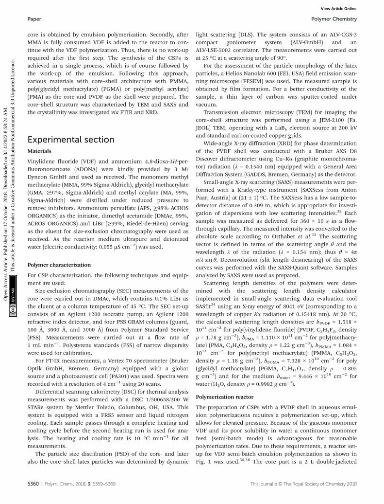
The preparation of CSPs with a PVDF shell in aqueous emul-sion polymerizations requires a polymerization set-up, whichallows for elevated pressure. Because of the gaseous monomerVDF and its poor solubility in water a continuous monomerfeed (semi-batch mode) is advantageous for reasonablepolymerization rates. Due to these requirements, a reactor set-up for VDF semi-batch emulsion polymerization as shown inFig. 1 was used.35,36 The core part is a 2 L double-jacketed
Paper Polymer Chemistry
5360 | Polym. Chem., 2018, 9, 5359–5369 This journal is © The Royal Society of Chemistry 2018
Ope
n A
cces
s A
rtic
le. P
ublis
hed
on 1
7 O
ctob
er 2
018.
Dow
nloa
ded
on 3
/14/
2022
8:5
8:24
AM
. T
his
artic
le is
lice
nsed
und
er a
Cre
ativ
e C
omm
ons
Attr
ibut
ion-
Non
Com
mer
cial
3.0
Unp
orte
d L
icen
ce.
View Article Online
stainless steel reactor with a bottom outlet (Büchi AG,Switzerland, Typ 3, max. 60 bar, 220 °C). The reactor is closedby a cover plate (Büchi AG, Switzerland, polyclave, 60 bar),which holds installations for pressure and temperaturemeasurement as well as fittings and valves for, e.g., addition ofliquids or purging with nitrogen. All the fittings, connectionsand valves were purchased from Swagelok®. The temperaturecontrol is established by a circulation thermostat (ministat240w, Huber Kältemaschinenbau AG, Germany). The pressureis measured using a Keller PA-21S/80400 pressure transducer.
During the reaction, temperature and pressure weremeasured, as well as stirring speed and the required torque.VDF is supplied to the reactor via a flexible 1/8″ copper pipe incombination with a pressure regulator (C200/1 TP B, Linde AG,Germany). This regulator is independent of the bottle pressureand ensures a constant reaction pressure during the semi-batch operation. The measurement of the continuouslyflowing VDF is carried out with a mass flow controller (MFC)(EL-FLOW®, Bronkhorst High-Tech BV, Netherlands). TheMFC is calibrated in the range from 1.2 to 60 g h−1 with anaccuracy of ±0.5%. Data of the VDF mass flow required to keepa constant pressure directly provide information on the solidcontent in the reactor and the polymerization rate. To achievegood mixing, a pitched blade agitator and a baffle areinstalled. For security reasons, the reactor is equipped with arupture disc and check valves in all pipes. Furthermore,
through a pressure sluice, liquids like initiator solution can beadded during the reaction.
Synthesis of the core–shell polymers
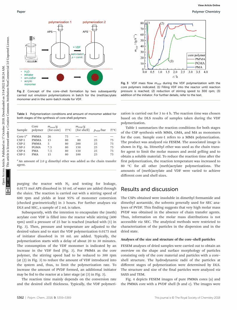
In order to prepare the CSP in an emulsion polymerization ina single process step without the need for work-up after syn-thesis of the core, already the core must be polymerized usinga stabilizer also suitable for the polymerization of VDF.37 Here,ADONA, a commercially used fluorinated stabilizer for VDFemulsion polymerizations, is employed. Firstly, the (meth)acrylic polymer is prepared in a batch emulsion polymeriz-ation in the reactor described above. Secondly, the emulsionpolymerization of VDF is performed in the semi-batch mode.Due to the low VDF solubility in the emulsion, it is fed con-tinuously into the reactor. The polymerization strategy is illus-trated in Fig. 2.
The core is typically synthesized as follows: 1100 ml de-ionized water is boiled for 45 minutes under a nitrogen flow toreduce the oxygen content. After cooling to room temperatureunder nitrogen, 10 g of the emulsifier ADONA and the acrylicmonomer (MMA, MA, or GMA) are added while stirring. Theamount of monomer added is given in Table 1. The mixture istreated with an ultrasonic sonotrode (UP200S, Fa. HielscherUltrasonics GmbH), which dips into the mixture. This emul-sion is transferred into the polymerization reactor, alreadyheated to the reaction temperature of 80 °C. After sealing,
Fig. 1 Schematic representation of the polymerization reactor. A: Reactor, B: stirrer, C: baffle, D: mass flow controller, E: stirrer motor with torquemeasurement, F: rupture disc, and G: bottom outlet.
Polymer Chemistry Paper
This journal is © The Royal Society of Chemistry 2018 Polym. Chem., 2018, 9, 5359–5369 | 5361
Ope
n A
cces
s A
rtic
le. P
ublis
hed
on 1
7 O
ctob
er 2
018.
Dow
nloa
ded
on 3
/14/
2022
8:5
8:24
AM
. T
his
artic
le is
lice
nsed
und
er a
Cre
ativ
e C
omm
ons
Attr
ibut
ion-
Non
Com
mer
cial
3.0
Unp
orte
d L
icen
ce.
View Article Online
purging the reactor with N2 and testing for leakage,0.0175 mol APS dissolved in 10 mL of water are added throughthe sluice. The reaction is carried out with a stirring speed of600 rpm and yields at least 95% of monomer conversion(checked gravimetrically) in 3 hours. For further analyses viaDLS and SEC, a sample of 2 mL is taken.
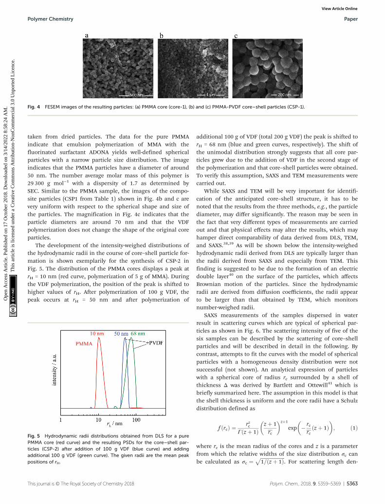
Subsequently, with the intention to encapsulate the (meth)acrylate core VDF is filled into the reactor while stirring (400rpm) until a pressure of 25 bar is reached (marked with (1) inFig. 3). Then, pressure and temperature are adjusted to thedesired values and to start the VDF polymerization 0.0175 molof initiator dissolved in 10 mL are added. Typically, thepolymerization starts with a delay of about 20 to 30 minutes.The consumption of the VDF monomer is indicated by anincrease in the VDF feed (Fig. 3). For PMMA as the corepolymer, the stirring speed had to be reduced to 300 rpm(at (2) in Fig. 3) to reduce the amount of VDF introduced intothe system and, thus, to limit the polymerization rate. Toincrease the amount of PVDF formed, an additional initiatormay be fed to the reactor at a later stage (at (3) in Fig. 3).
The reaction time mainly depends on the conversion rateand the desired shell thickness. Typically, the VDF polymeri-
zation is carried out for 3 to 4 h. The reaction time was chosenbased on the DLS results of samples taken during the VDFpolymerization.
Table 1 summarizes the reaction conditions for both stagesof the CSP synthesis with MMA, GMA, and MA as monomersfor the core. Sample core-1 refers to a MMA polymerization.The product was analyzed via FESEM. The associated image isshown in Fig. 4a. Dimethyl ether was used as the chain trans-fer agent to limit the molar masses and avoid gelling and toobtain a soluble material. To reduce the reaction time after thefirst polymerization, the reaction temperature was increased to80 °C for all other (meth)acrylate polymerizations. Theamounts of (meth)acrylate and VDF were varied to achievedifferent core and shell sizes.
Results and discussion
The CSPs obtained were insoluble in dimethyl formamide anddimethyl acetamide, the solvents generally used for SEC ana-lyses of PVDF. This finding suggests that very high molar massPVDF was obtained in the absence of chain transfer agents.Thus, information on the molar mass distributions is notaccessible via SEC. The analytical methods were restricted tocharacterization of the particles in the dispersion and in thedried state.
Analyses of the size and structure of the core–shell particles
FESEM analyses of dried samples were carried out to obtain anoverview on the shape and surface morphology of particlesconsisting only of the core material and particles with a core–shell structure. The hydrodynamic radii of the particles atdifferent stages of polymerization were determined by DLS.The structure and size of the final particles were analyzed viaSAXS and TEM.
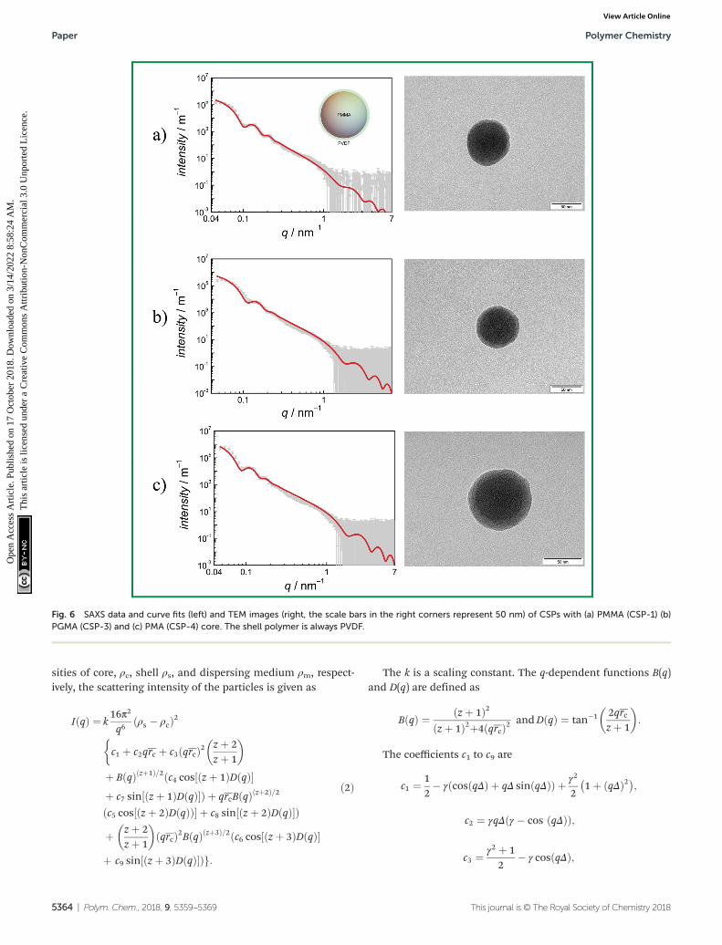
Fig. 4 depicts FESEM images of pure PMMA cores (a) andthe PMMA core with a PVDF shell (b and c). The images were
Fig. 2 Concept of the core–shell formation by two subsequentlycarried out emulsion polymerizations in batch for the (meth)acrylatemonomer and in the semi-batch mode for VDF.
Table 1 Polymerization conditions and amount of monomer added forboth stages of the synthesis of core shell polymers
SampleCorepolymer
mmon/g(for core) T/°C
mVDF/g(for shell) pVDF/bar T/°C
Core-1a PMMA 26 75 — — —CSP-1 PMMA 15 80 80 25 75CSP-2 PMMA 5 80 200 25 75CSP-3 PGMA 7.5 80 150 25 75CSP-4 PMA 7.5 80 150 25 75CSP-5 PMA 15 80 100 25 75
a An amount of 2.0 g dimethyl ether was added as the chain transferagent.
Fig. 3 VDF mass flow mVDF during the VDF polymerization with thecore polymers indicated. (1) Filling VDF into the reactor until reactionpressure is reached; (2) reduction of stirring speed to 300 rpm; (3)addition of the initiator. For further details, refer to the text.
Paper Polymer Chemistry
5362 | Polym. Chem., 2018, 9, 5359–5369 This journal is © The Royal Society of Chemistry 2018
Ope
n A
cces
s A
rtic
le. P
ublis
hed
on 1
7 O
ctob
er 2
018.
Dow
nloa
ded
on 3
/14/
2022
8:5
8:24
AM
. T
his
artic
le is
lice
nsed
und
er a
Cre
ativ
e C
omm
ons
Attr
ibut
ion-
Non
Com
mer
cial
3.0
Unp
orte
d L
icen
ce.
View Article Online
taken from dried particles. The data for the pure PMMAindicate that emulsion polymerization of MMA with thefluorinated surfactant ADONA yields well-defined sphericalparticles with a narrow particle size distribution. The imageindicates that the PMMA particles have a diameter of around50 nm. The number average molar mass of this polymer is29 300 g mol−1 with a dispersity of 1.7 as determined bySEC. Similar to the PMMA sample, the images of the compo-site particles (CSP1 from Table 1) shown in Fig. 4b and c arevery uniform with respect to the spherical shape and size ofthe particles. The magnification in Fig. 4c indicates that theparticle diameters are around 70 nm and that the VDFpolymerization does not change the shape of the original coreparticles.
The development of the intensity-weighed distributions ofthe hydrodynamic radii in the course of core–shell particle for-mation is shown exemplarily for the synthesis of CSP-2 inFig. 5. The distribution of the PMMA cores displays a peak atrH = 10 nm (red curve, polymerization of 5 g of MMA). Duringthe VDF polymerization, the position of the peak is shifted tohigher values of rH. After polymerization of 100 g VDF, thepeak occurs at rH = 50 nm and after polymerization of
additional 100 g of VDF (total 200 g VDF) the peak is shifted torH = 68 nm (blue and green curves, respectively). The shift ofthe unimodal distribution strongly suggests that all core par-ticles grew due to the addition of VDF in the second stage ofthe polymerization and that core–shell particles were obtained.To verify this assumption, SAXS and TEM measurements werecarried out.
While SAXS and TEM will be very important for identifi-cation of the anticipated core–shell structure, it has to benoted that the results from the three methods, e.g., the particlediameter, may differ significantly. The reason may be seen inthe fact that very different types of measurements are carriedout and that physical effects may alter the results, which mayhamper direct comparability of data derived from DLS, TEM,and SAXS.38,39 As will be shown below the intensity-weighedhydrodynamic radii derived from DLS are typically larger thanthe radii derived from SAXS and especially from TEM. Thisfinding is suggested to be due to the formation of an electricdouble layer40 on the surface of the particles, which affectsBrownian motion of the particles. Since the hydrodynamicradii are derived from diffusion coefficients, the radii appearto be larger than that obtained by TEM, which monitorsnumber-weighed radii.
SAXS measurements of the samples dispersed in waterresult in scattering curves which are typical of spherical par-ticles as shown in Fig. 6. The scattering intensity of five of thesix samples can be described by the scattering of core–shellparticles and will be described in detail in the following. Bycontrast, attempts to fit the curves with the model of sphericalparticles with a homogeneous density distribution were notsuccessful (not shown). An analytical expression of particleswith a spherical core of radius rc surrounded by a shell ofthickness Δ was derived by Bartlett and Ottewill41 which isbriefly summarized here. The assumption in this model is thatthe shell thickness is uniform and the core radii have a Schulzdistribution defined as
f rcð Þ ¼ rzcΓ z þ 1ð Þ
z þ 1rc
� �zþ1
exp � rcrc
z þ 1ð Þ� �
; ð1Þ
where rc is the mean radius of the cores and z is a parameterfrom which the relative widths of the size distribution σc canbe calculated as σc ¼
ffiffiffiffiffiffiffiffiffiffiffiffiffiffiffiffiffiffiffiffi1=ðz þ 1Þp
. For scattering length den-
Fig. 4 FESEM images of the resulting particles: (a) PMMA core (core-1), (b) and (c) PMMA-PVDF core–shell particles (CSP-1).
Fig. 5 Hydrodynamic radii distributions obtained from DLS for a purePMMA core (red curve) and the resulting PSDs for the core–shell par-ticles (CSP-2) after addition of 100 g VDF (blue curve) and addingadditional 100 g VDF (green curve). The given radii are the mean peakpositions of rH.
Polymer Chemistry Paper
This journal is © The Royal Society of Chemistry 2018 Polym. Chem., 2018, 9, 5359–5369 | 5363
Ope
n A
cces
s A
rtic
le. P
ublis
hed
on 1
7 O
ctob
er 2
018.
Dow
nloa
ded
on 3
/14/
2022
8:5
8:24
AM
. T
his
artic
le is
lice
nsed
und
er a
Cre
ativ
e C
omm
ons
Attr
ibut
ion-
Non
Com
mer
cial
3.0
Unp
orte
d L
icen
ce.
View Article Online
sities of core, ρc, shell ρs, and dispersing medium ρm, respect-ively, the scattering intensity of the particles is given as
I qð Þ ¼ k16π2
q6ρs � ρcð Þ2
c1 þ c2qrc þ c3 qrcð Þ2 z þ 2z þ 1
� ��
þ B qð Þ zþ1ð Þ=2 c4 cos½ðz þ 1ÞDðqð Þ�þ c7 sin ðz þ 1ÞDðqÞ½ �Þ þ qrcBðqÞðzþ2Þ=2
c5 cos½ðz þ 2ÞDðqÞð Þ� þ c8 sin½ðz þ 2ÞDðqÞ�Þ
þ z þ 2z þ 1
� �qrcð Þ2BðqÞðzþ3Þ=2ðc6 cos z þ 3ð ÞDðqÞ½ �
þ c9 sin½ðz þ 3ÞDðqÞ�Þg:
ð2Þ
The k is a scaling constant. The q-dependent functions B(q)and D(q) are defined as
BðqÞ ¼ z þ 1ð Þ2z þ 1ð Þ2þ4 qrcð Þ2 andDðqÞ ¼ tan�1 2qrc
z þ 1
� �:
The coefficients c1 to c9 are
c1 ¼ 12� γ cos qΔð Þ þ qΔ sin qΔð Þð Þ þ γ2
21þ qΔð Þ2� �
;
c2 ¼ γqΔðγ � cos ðqΔÞÞ;
c3 ¼ γ2 þ 12
� γ cos qΔð Þ;
Fig. 6 SAXS data and curve fits (left) and TEM images (right, the scale bars in the right corners represent 50 nm) of CSPs with (a) PMMA (CSP-1) (b)PGMA (CSP-3) and (c) PMA (CSP-4) core. The shell polymer is always PVDF.
Paper Polymer Chemistry
5364 | Polym. Chem., 2018, 9, 5359–5369 This journal is © The Royal Society of Chemistry 2018
Ope
n A
cces
s A
rtic
le. P
ublis
hed
on 1
7 O
ctob
er 2
018.
Dow
nloa
ded
on 3
/14/
2022
8:5
8:24
AM
. T
his
artic
le is
lice
nsed
und
er a
Cre
ativ
e C
omm
ons
Attr
ibut
ion-
Non
Com
mer
cial
3.0
Unp
orte
d L
icen
ce.
View Article Online
c4 ¼ γ 2½qΔ cosðqΔÞ � sinðqΔÞ�2 � c1;
c5 ¼ 2γ sinðqΔÞ½1� γðqΔ sinðqΔÞ þ cosðqΔÞÞ� þ c2;
c6 ¼ c3 � γ 2 sin2 ðqΔÞ;
c7 ¼ γ sin qΔð Þ � γ2
21þ qΔð Þ2� �
sin 2qΔð Þ � c5;
c8 ¼ c4 � 12þ γ cos qΔð Þ � γ2
21þ qΔð Þ2� �
cos 2qΔð Þ;
c9 ¼ γ sinðqΔ½1� γ cosðqΔÞ�Þ:The γ is the ratio of the contrast between medium and
shell, ρm − ρs, and between the core and the shell, ρc − ρs, i.e.γ = (ρm − ρs)/(ρc − ρs). If the shell has the same electrondensity as the dispersing medium ρm = ρs, the γ = 0 and onlythe core contributes to the scattering. If the core has the samedensity as the dispersing medium ρc = ρm, the γ = 1 and onlythe shell contributes to the scattering.
Eqn (2) was employed for interpretation of the scatteringdata of five of the samples and results in fit curves shown inFig. 6 (grey and red lines, respectively). Note that the shellthickness was used as the fixed parameter during curve fittingto avoid ambiguous results. Also the density of the shellmaterial was held constant at curve fitting using the density ofPVDF in the bulk material of 1.78 g cm−3 to avoid ambiguousfits. Fit results are given in the figure captions and in Table 2.
The density of the cores was in all cases found to be higherthan that of the core material in the bulk form. This leads tothe assumption that PVDF may be partially incorporated intothe core. Then the volume fractions ϕc of PMMA, PGMA, andPMA, respectively, as the core material are less than 1. Theirvolume fractions were estimated according to eqn (3),
ϕc ¼ρc � ρs
ρc;bulk � ρs; ð3Þ
where ρc, bulk is the density of PMMA, PGMA and PMA in theform of a bulk material. When applying this estimate theamount of core material PMMA, PGMA and PMA, respectively,ranges between 30 and 56% (see in Table 2). These values indi-cate that the amount of PVDF in the cores is significant.
The data in Table 2 show that the fraction of the acrylate ormethacrylate monomer in the core is rather similar for allsamples with the exception of sample CSP-4. The finding israther surprising since the amounts of the (meth)acrylatemonomer and VDF used during polymerization are quitedifferent. The data may be interpreted, if it is assumed thatVDF dissolves in the core particles at the beginning of thesecond stage of the polymerization. At this point, VDF is fedinto the emulsion until a constant pressure is reached. It isknown that in particular VDF and MMA units may show favor-able interactions, which is the reason for rather good miscibil-ity of PVDF and PMMA blends.18,19,42 Thus, it appears reason-able to assume VDF and PVDF solubility in the methacrylatecore. The SAXS and TEM data strongly suggest that the coreconstitutes of a mixture of both polymers since no signs of seg-regation are seen. It may be anticipated that gaseous VDFenters into the particles. Upon entry of a radical formed in theaqueous phase, the VDF monomer in the core is polymerizedleading to a mixture of PMMA and PVDF. In addition, smallamounts of a statistical copolymer consisting of VDF andresidual (meth)acrylate monomer are formed. The shell of theparticle is clearly visible and suggests that the shell consistsonly of PVDF. This observation may be explained by reaching asolubility limit for VDF inside the core material.
Initially, within the experiments the amount of monomerfor the core was varied to allow for the formation of differentcore sizes. The resulting core sizes range from 33 to 45 nm,with PVDF volume fractions inside the core of around 30%.Only in the case of CSP-4, a deviating PVDF volume fraction of56% was reached. Thus, generally the core sizes do not scalewith the amount of the (meth)acrylate monomer used.
Fig. 6 gives the SAXS results (scattering curves and curve fitsapplying a core shell model (grey symbols and red solid line,respectively)) and TEM images for CSP-1, CSP-3 and CSP-4.The systems may be described as follows: (a) the core radiusformed by PMMA is rc = (38.2 ± 0.7) nm with a dispersity of0.12. The shell formed by PDVF has a thickness of 4.0 nm andwas held constant at curve fitting to avoid ambiguous results.The relative volume of the core is (74 ± 6) %. The TEM pictureconfirms a broad distribution of shell thicknesses. (b) Thecore radius formed by PGMA is rc = (33.9 ± 1.0) nm with a dis-persity of 0.14. The shell formed by PDVF has a thickness of3.5 nm and was held constant at curve fitting to avoid ambigu-ous results. The relative volume of the core to the total volumeis (74 ± 11) %. The TEM picture displays a core–shell structure.(c) The core radius in the second system with PMA is rc =(45.2 ± 0.30) nm with a dispersity of 0.12 and the shell formedby PDVF has a thickness of 3.5 nm, which was held constant atcurve fitting to avoid ambiguous results. The relative volumeof the core to the total volume is (80 ± 2) %. The TEM picturedisplays a core–shell structure.
The analytical results given in Table 3 indicate that at least75% of the CSP is given by the core. As discussed above thecore is a mixture of both polymers. The pure PVDF shells showjust very small differences. It has to be noted that the volumeincrease of the shell is not directly proportional to its thick-
Table 2 Characteristics of the core–shell particles derived from SAXScurve fit analysis are density of the core material in bulk form ρc, bulk,core material of the particles ρc, shell material ρs, mean core radius rc,relative width of distribution of core sizes σ, the thickness of the shell Δand the volume fraction, ϕc, according to eqn (3). The density of the dis-persant matrix (water) ρm = 0.998 g cm−3 and the shell (PVDF) ρs =1.78 g cm−3 was held constant at curve fitting
Sampleρc, bulk[g cm−3]
ρc[g cm−3] rc[nm] σ [%] Δ [nm] ϕc
CSP-1 1.18 1.60 ± 0.15 38.2 ± 0.7 12 4.0 0.30CSP-2 1.18 1.60 ± 0.05 45.1 ± 0.3 10 3.5 0.30CSP-3 0.805 1.50 ± 0.21 33.9 ± 1.0 14 3.5 0.29CSP-4 1.22 1.46 ± 0.04 45.2 ± 0.3 12 3.5 0.56CSP-5 1.22 1.60 ± 0.06 33.2 ± 0.4 12 3.8 0.30
Polymer Chemistry Paper
This journal is © The Royal Society of Chemistry 2018 Polym. Chem., 2018, 9, 5359–5369 | 5365
Ope
n A
cces
s A
rtic
le. P
ublis
hed
on 1
7 O
ctob
er 2
018.
Dow
nloa
ded
on 3
/14/
2022
8:5
8:24
AM
. T
his
artic
le is
lice
nsed
und
er a
Cre
ativ
e C
omm
ons
Attr
ibut
ion-
Non
Com
mer
cial
3.0
Unp
orte
d L
icen
ce.
View Article Online
ness, but to the third power of the thickness (Δ3). These resultsindicate that DLS measurements can only provide a verygeneral picture of the variation in hydrodynamic radii of theparticles in total. For example, fine details such as growth ofthe core and the shell during the second stage of the polymer-ization were not accessible. All analytical methods discussedindicate that narrow particle size distributions were obtained,and indicated a uniform growth of all composite particles.
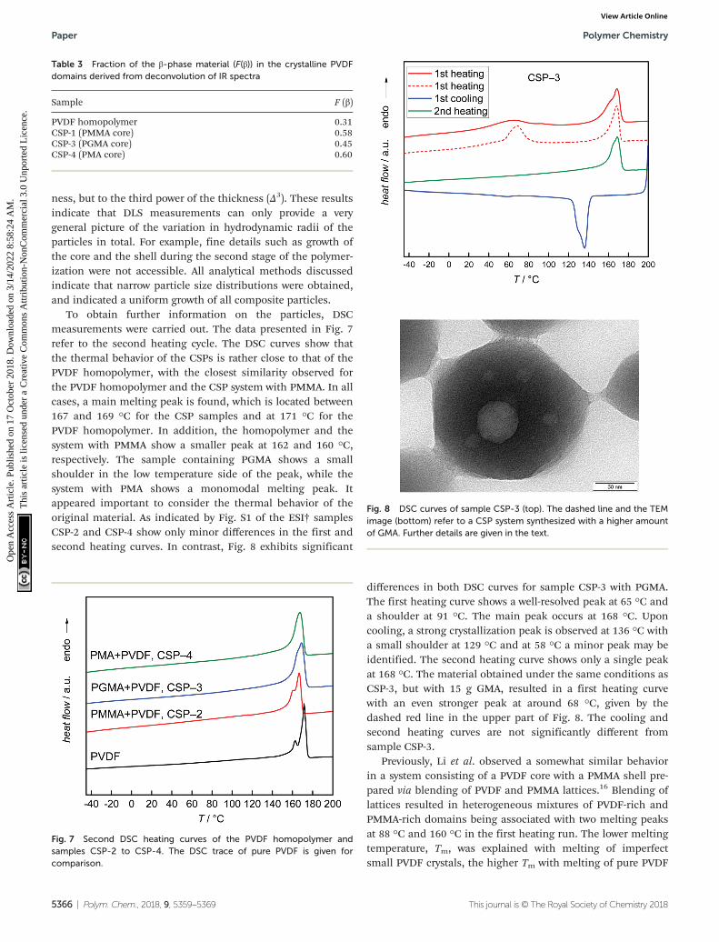
To obtain further information on the particles, DSCmeasurements were carried out. The data presented in Fig. 7refer to the second heating cycle. The DSC curves show thatthe thermal behavior of the CSPs is rather close to that of thePVDF homopolymer, with the closest similarity observed forthe PVDF homopolymer and the CSP system with PMMA. In allcases, a main melting peak is found, which is located between167 and 169 °C for the CSP samples and at 171 °C for thePVDF homopolymer. In addition, the homopolymer and thesystem with PMMA show a smaller peak at 162 and 160 °C,respectively. The sample containing PGMA shows a smallshoulder in the low temperature side of the peak, while thesystem with PMA shows a monomodal melting peak. Itappeared important to consider the thermal behavior of theoriginal material. As indicated by Fig. S1 of the ESI† samplesCSP-2 and CSP-4 show only minor differences in the first andsecond heating curves. In contrast, Fig. 8 exhibits significant
differences in both DSC curves for sample CSP-3 with PGMA.The first heating curve shows a well-resolved peak at 65 °C anda shoulder at 91 °C. The main peak occurs at 168 °C. Uponcooling, a strong crystallization peak is observed at 136 °C witha small shoulder at 129 °C and at 58 °C a minor peak may beidentified. The second heating curve shows only a single peakat 168 °C. The material obtained under the same conditions asCSP-3, but with 15 g GMA, resulted in a first heating curvewith an even stronger peak at around 68 °C, given by thedashed red line in the upper part of Fig. 8. The cooling andsecond heating curves are not significantly different fromsample CSP-3.
Previously, Li et al. observed a somewhat similar behaviorin a system consisting of a PVDF core with a PMMA shell pre-pared via blending of PVDF and PMMA lattices.16 Blending oflattices resulted in heterogeneous mixtures of PVDF-rich andPMMA-rich domains being associated with two melting peaksat 88 °C and 160 °C in the first heating run. The lower meltingtemperature, Tm, was explained with melting of imperfectsmall PVDF crystals, the higher Tm with melting of pure PVDF
Table 3 Fraction of the β-phase material (F(β)) in the crystalline PVDFdomains derived from deconvolution of IR spectra
Sample F (β)
PVDF homopolymer 0.31CSP-1 (PMMA core) 0.58CSP-3 (PGMA core) 0.45CSP-4 (PMA core) 0.60
Fig. 7 Second DSC heating curves of the PVDF homopolymer andsamples CSP-2 to CSP-4. The DSC trace of pure PVDF is given forcomparison.
Fig. 8 DSC curves of sample CSP-3 (top). The dashed line and the TEMimage (bottom) refer to a CSP system synthesized with a higher amountof GMA. Further details are given in the text.
Paper Polymer Chemistry
5366 | Polym. Chem., 2018, 9, 5359–5369 This journal is © The Royal Society of Chemistry 2018
Ope
n A
cces
s A
rtic
le. P
ublis
hed
on 1
7 O
ctob
er 2
018.
Dow
nloa
ded
on 3
/14/
2022
8:5
8:24
AM
. T
his
artic
le is
lice
nsed
und
er a
Cre
ativ
e C
omm
ons
Attr
ibut
ion-
Non
Com
mer
cial
3.0
Unp
orte
d L
icen
ce.
View Article Online
crystals. The second run showed only a single peak at 156 °C.Following the explanation given in ref. 16, a single Tm at hightemperatures suggests that only large crystals of pure PVDF arepresent. If these findings are transferred to sample CSP-3, itmay be suggested that firstly, a rather heterogeneous systemwith pure well-crystallized PVDF domains and some smallimperfect PVDF crystals is present. Upon heating, intermixingoccurs and the small imperfect PVDF crystallites disappear. Inthis context, the DSC results for CSP-2 and CSP-4 with PMMAand PMA suggest that only large PVDF crystals are present.Imperfect mixing induced small crystallites do not occur.
In addition, TGA measurements were carried out. Theresults shown in Fig. S3 of the ESI† indicate only minor differ-ences between the composite particles and pure PVDF. In thepresence of the non-fluorinated polymers PGMA (CSP-3) andPMA (CSP-4) slight decomposition of around 4% is alreadyseen at 300 °C.
Together with the findings from SAXS the DSC data suggestthat in the case of CSP-2 and CSP-4 well mixed cores consistingof both polymers with a shell of pure PVDF occur. CSP-3 issuggested to consist of a more heterogeneous core consisting ofPGMA and PVDF surrounded by a shell of pure PVDF. This expla-nation is in line with the finding that some samples consistingof PVDF and larger amounts of PGMA lead to TEM images thatshow a core with some round inclusions (see the lower part ofFig. 8). Again a shell of PVDF was found. Furthermore, as men-tioned above SAXS analyses of these samples applying a coreshell structure were not successful. These significant differencesbetween systems with PGMA and systems with PMMA or PMAare suggested to be due to differences in interactions betweenPVDF and the (meth)acrylate component.
Crystallinity of the shell PVDF
To obtain information on the crystallinity of the PVDF shell,FT-IR and XRD measurements were carried out. The FT-IR
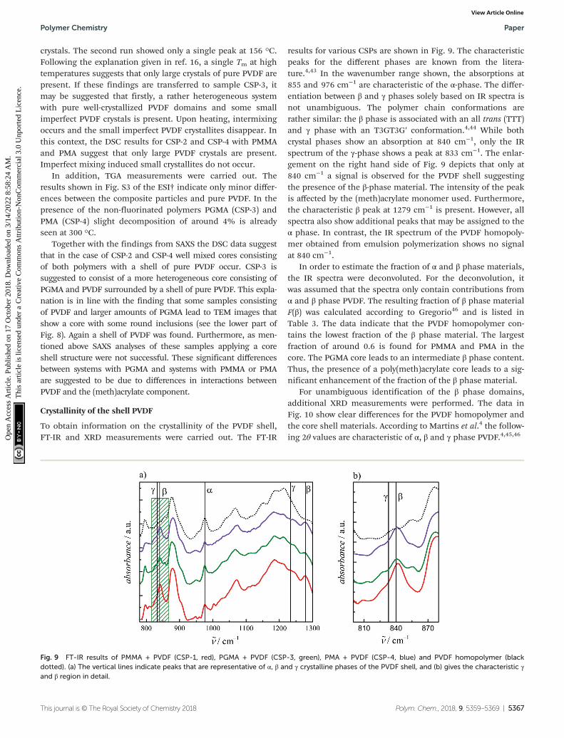
results for various CSPs are shown in Fig. 9. The characteristicpeaks for the different phases are known from the litera-ture.4,43 In the wavenumber range shown, the absorptions at855 and 976 cm−1 are characteristic of the α-phase. The differ-entiation between β and γ phases solely based on IR spectra isnot unambiguous. The polymer chain conformations arerather similar: the β phase is associated with an all trans (TTT)and γ phase with an T3GT3G′ conformation.4,44 While bothcrystal phases show an absorption at 840 cm−1, only the IRspectrum of the γ-phase shows a peak at 833 cm−1. The enlar-gement on the right hand side of Fig. 9 depicts that only at840 cm−1 a signal is observed for the PVDF shell suggestingthe presence of the β-phase material. The intensity of the peakis affected by the (meth)acrylate monomer used. Furthermore,the characteristic β peak at 1279 cm−1 is present. However, allspectra also show additional peaks that may be assigned to theα phase. In contrast, the IR spectrum of the PVDF homopoly-mer obtained from emulsion polymerization shows no signalat 840 cm−1.
In order to estimate the fraction of α and β phase materials,the IR spectra were deconvoluted. For the deconvolution, itwas assumed that the spectra only contain contributions fromα and β phase PVDF. The resulting fraction of β phase materialF(β) was calculated according to Gregorio46 and is listed inTable 3. The data indicate that the PVDF homopolymer con-tains the lowest fraction of the β phase material. The largestfraction of around 0.6 is found for PMMA and PMA in thecore. The PGMA core leads to an intermediate β phase content.Thus, the presence of a poly(meth)acrylate core leads to a sig-nificant enhancement of the fraction of the β phase material.
For unambiguous identification of the β phase domains,additional XRD measurements were performed. The data inFig. 10 show clear differences for the PVDF homopolymer andthe core shell materials. According to Martins et al.4 the follow-ing 2θ values are characteristic of α, β and γ phase PVDF.4,45,46
Fig. 9 FT-IR results of PMMA + PVDF (CSP-1, red), PGMA + PVDF (CSP-3, green), PMA + PVDF (CSP-4, blue) and PVDF homopolymer (blackdotted). (a) The vertical lines indicate peaks that are representative of α, β and γ crystalline phases of the PVDF shell, and (b) gives the characteristic γand β region in detail.
Polymer Chemistry Paper
This journal is © The Royal Society of Chemistry 2018 Polym. Chem., 2018, 9, 5359–5369 | 5367
Ope
n A
cces
s A
rtic
le. P
ublis
hed
on 1
7 O
ctob
er 2
018.
Dow
nloa
ded
on 3
/14/
2022
8:5
8:24
AM
. T
his
artic
le is
lice
nsed
und
er a
Cre
ativ
e C
omm
ons
Attr
ibut
ion-
Non
Com
mer
cial
3.0
Unp
orte
d L
icen
ce.
View Article Online
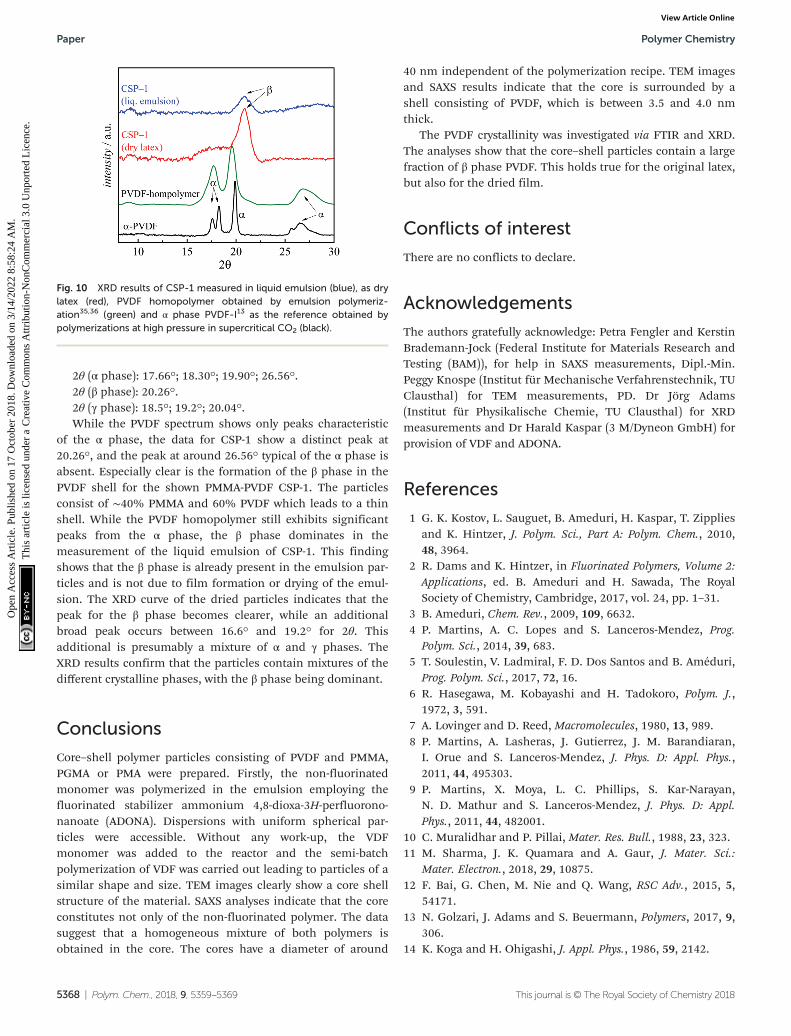
2θ (α phase): 17.66°; 18.30°; 19.90°; 26.56°.2θ (β phase): 20.26°.2θ (γ phase): 18.5°; 19.2°; 20.04°.While the PVDF spectrum shows only peaks characteristic
of the α phase, the data for CSP-1 show a distinct peak at20.26°, and the peak at around 26.56° typical of the α phase isabsent. Especially clear is the formation of the β phase in thePVDF shell for the shown PMMA-PVDF CSP-1. The particlesconsist of ∼40% PMMA and 60% PVDF which leads to a thinshell. While the PVDF homopolymer still exhibits significantpeaks from the α phase, the β phase dominates in themeasurement of the liquid emulsion of CSP-1. This findingshows that the β phase is already present in the emulsion par-ticles and is not due to film formation or drying of the emul-sion. The XRD curve of the dried particles indicates that thepeak for the β phase becomes clearer, while an additionalbroad peak occurs between 16.6° and 19.2° for 2θ. Thisadditional is presumably a mixture of α and γ phases. TheXRD results confirm that the particles contain mixtures of thedifferent crystalline phases, with the β phase being dominant.
Conclusions
Core–shell polymer particles consisting of PVDF and PMMA,PGMA or PMA were prepared. Firstly, the non-fluorinatedmonomer was polymerized in the emulsion employing thefluorinated stabilizer ammonium 4,8-dioxa-3H-perfluorono-nanoate (ADONA). Dispersions with uniform spherical par-ticles were accessible. Without any work-up, the VDFmonomer was added to the reactor and the semi-batchpolymerization of VDF was carried out leading to particles of asimilar shape and size. TEM images clearly show a core shellstructure of the material. SAXS analyses indicate that the coreconstitutes not only of the non-fluorinated polymer. The datasuggest that a homogeneous mixture of both polymers isobtained in the core. The cores have a diameter of around
40 nm independent of the polymerization recipe. TEM imagesand SAXS results indicate that the core is surrounded by ashell consisting of PVDF, which is between 3.5 and 4.0 nmthick.
The PVDF crystallinity was investigated via FTIR and XRD.The analyses show that the core–shell particles contain a largefraction of β phase PVDF. This holds true for the original latex,but also for the dried film.
Conflicts of interest
There are no conflicts to declare.
Acknowledgements
The authors gratefully acknowledge: Petra Fengler and KerstinBrademann-Jock (Federal Institute for Materials Research andTesting (BAM)), for help in SAXS measurements, Dipl.-Min.Peggy Knospe (Institut für Mechanische Verfahrenstechnik, TUClausthal) for TEM measurements, PD. Dr Jörg Adams(Institut für Physikalische Chemie, TU Clausthal) for XRDmeasurements and Dr Harald Kaspar (3 M/Dyneon GmbH) forprovision of VDF and ADONA.
References
1 G. K. Kostov, L. Sauguet, B. Ameduri, H. Kaspar, T. Zippliesand K. Hintzer, J. Polym. Sci., Part A: Polym. Chem., 2010,48, 3964.
2 R. Dams and K. Hintzer, in Fluorinated Polymers, Volume 2:Applications, ed. B. Ameduri and H. Sawada, The RoyalSociety of Chemistry, Cambridge, 2017, vol. 24, pp. 1–31.
3 B. Ameduri, Chem. Rev., 2009, 109, 6632.4 P. Martins, A. C. Lopes and S. Lanceros-Mendez, Prog.
Polym. Sci., 2014, 39, 683.5 T. Soulestin, V. Ladmiral, F. D. Dos Santos and B. Améduri,
Prog. Polym. Sci., 2017, 72, 16.6 R. Hasegawa, M. Kobayashi and H. Tadokoro, Polym. J.,
1972, 3, 591.7 A. Lovinger and D. Reed, Macromolecules, 1980, 13, 989.8 P. Martins, A. Lasheras, J. Gutierrez, J. M. Barandiaran,
I. Orue and S. Lanceros-Mendez, J. Phys. D: Appl. Phys.,2011, 44, 495303.
9 P. Martins, X. Moya, L. C. Phillips, S. Kar-Narayan,N. D. Mathur and S. Lanceros-Mendez, J. Phys. D: Appl.Phys., 2011, 44, 482001.
10 C. Muralidhar and P. Pillai, Mater. Res. Bull., 1988, 23, 323.11 M. Sharma, J. K. Quamara and A. Gaur, J. Mater. Sci.:
Mater. Electron., 2018, 29, 10875.12 F. Bai, G. Chen, M. Nie and Q. Wang, RSC Adv., 2015, 5,
54171.13 N. Golzari, J. Adams and S. Beuermann, Polymers, 2017, 9,
306.14 K. Koga and H. Ohigashi, J. Appl. Phys., 1986, 59, 2142.
Fig. 10 XRD results of CSP-1 measured in liquid emulsion (blue), as drylatex (red), PVDF homopolymer obtained by emulsion polymeriz-ation35,36 (green) and α phase PVDF-I13 as the reference obtained bypolymerizations at high pressure in supercritical CO2 (black).
Paper Polymer Chemistry
5368 | Polym. Chem., 2018, 9, 5359–5369 This journal is © The Royal Society of Chemistry 2018
Ope
n A
cces
s A
rtic
le. P
ublis
hed
on 1
7 O
ctob
er 2
018.
Dow
nloa
ded
on 3
/14/
2022
8:5
8:24
AM
. T
his
artic
le is
lice
nsed
und
er a
Cre
ativ
e C
omm
ons
Attr
ibut
ion-
Non
Com
mer
cial
3.0
Unp
orte
d L
icen
ce.
View Article Online
15 H. S. Nalwa and M. Dekker, Ferroelectric Polymers, Crc PressInc, New York, 1995.
16 Y. Li, G. Zhang, S. Song, H. Xu, M. Pan and G.-J. Zhong,Polymers, 2017, 9, 448.
17 D. Yang, H. Xu, W. Yu, J. Wang and X. Gong, J. Mater. Sci.:Mater. Electron., 2017, 28, 13006.
18 T. Nishi and T. T. Wang, Macromolecules, 1975, 8, 909.19 C. Leonard, J. L. Halary and L. Monnerie, Macromolecules,
1988, 21, 2988.20 W. Yan, M. Pan, J. Yuan, G. Liu, L. Cui, G. Zhang and
L. Zhu, Polymer, 2017, 122, 139.21 M. Pan, L. Yang, B. Guan, M. Lu, G. Zhong and L. Zhu, Soft
Matter, 2011, 7, 11187.22 M. Pan, L. Yang, J. Wang, S. Tang, G. Zhong, R. Su,
M. K. Sen, M. K. Endoh, T. Koga and L. Zhu,Macromolecules, 2014, 47, 2632.
23 N. Durand, P. Gaveau, G. Silly, B. Améduri and B. Boutevin,Macromolecules, 2011, 44, 6249.
24 N. Durand, B. Boutevin, G. Silly and B. Améduri,Macromolecules, 2011, 44, 8487.
25 N. Badi, R. Mekala, S. Khasim, A. S. Roy and A. Ignatiev,J. Mater. Sci.: Mater. Electron., 2018, 29, 10593.
26 T. Chen, Q. Tang, B. Wang, Y. Li and L. Liu, Mater. Lett.,2015, 159, 413.
27 D. Mondal, A. L. Gayen, B. K. Paul, P. Bandyopadhyay,D. Bera, D. S. Bhar, K. Das, P. Nandy and S. Das, J. Mater.Sci.: Mater. Electron., 2018, 321, 651.
28 L. Xie, X. Huang, K. Yang, S. Li and P. Jiang, J. Mater.Chem. A, 2014, 2, 5244.
29 T. Chen and B. Liu, Mater. Lett., 2018, 210, 165.
30 M. S. Sebastian, A. Larrea, R. Gonçalves, T. Alejo, J. L. Vilas,V. Sebastian, P. Martins and S. Lanceros-Mendez, RSC Adv.,2016, 6, 113007.
31 W.-H. Li and H. D. H. Stöver, Macromolecules, 2000, 33,4354.
32 A. Bergmann, D. Orthaber, G. Scherf and O. Glatter, J. Appl.Crystallogr., 2000, 33, 869.
33 D. Orthaber, A. Bergmann and O. Glatter, J. Appl.Crystallogr., 2000, 33, 218.
34 I. Bressler, J. Kohlbrecher and A. F. Thünemann, J. Appl.Crystallogr., 2015, 48, 1587.
35 F. Brandl, M. Drache and S. Beuermann, Polymers, 2018,10, 1008.
36 F. Brandl and S. Beuermann, Chem. Ing. Tech., 2018, 90, 372.37 S. Banerjee, J. Schmidt, Y. Talmon, H. Hori, T. Asai and
B. Ameduri, Chem. Commun., 2018, 54, 11399.38 S. Pabisch, B. Feichtenschlager, G. Kickelbick and
H. Peterlik, Chem. Phys. Lett., 2012, 521, 91.39 R. Brydson, A. Brown, C. Hodges, P. Abellan and
N. Hondow, J. Microsc., 2015, 260, 238.40 S. Bhattacharjee, J. Controlled Release, 2016, 235, 337.41 P. Bartlett and R. H. Ottewill, Colloidal Crystal, 1992, 96,
3306.42 W. Fan and S. Zheng, J. Polym. Sci., Part B: Polym. Phys.,
2007, 45, 2580.43 T. Boccaccio, A. Bottino, G. Capannelli and P. Piaggio,
J. Membr. Sci., 2002, 210, 315.44 A. J. Lovinger, Macromolecules, 1982, 15, 40.45 R. Gregorio, J. Appl. Polym. Sci., 2006, 100, 3272.46 L. Priya and J. P. Jog, J. Appl. Polym. Sci., 2003, 89, 2036.
Polymer Chemistry Paper
This journal is © The Royal Society of Chemistry 2018 Polym. Chem., 2018, 9, 5359–5369 | 5369
Ope
n A
cces
s A
rtic
le. P
ublis
hed
on 1
7 O
ctob
er 2
018.
Dow
nloa
ded
on 3
/14/
2022
8:5
8:24
AM
. T
his
artic
le is
lice
nsed
und
er a
Cre
ativ
e C
omm
ons
Attr
ibut
ion-
Non
Com
mer
cial
3.0
Unp
orte
d L
icen
ce.
View Article Online


![Spectral and Scattering Theory for Space-Cutoff ϕ Models ...c... · The spectral and scattering theory of H was studied in [2] by adapting meth-ods originally developed for N-particle](https://static.fdocument.org/doc/165x107/5f700db082dc1c0e0a57dc62/spectral-and-scattering-theory-for-space-cutoi-models-c-the-spectral.jpg)