Perspectives of the PROTO-SPHERA experiment · 2015-10-29 · Prolated low aspect ratio ST...
16
Perspectives of the PROTO-SPHERA experiment P. Micozzi, F. Alladio, A. Lampasi, G. Maffia ISTW2015 | Princeton, 3-6 November
Transcript of Perspectives of the PROTO-SPHERA experiment · 2015-10-29 · Prolated low aspect ratio ST...
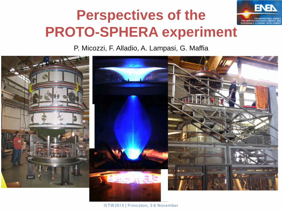
Perspectives of the PROTO-SPHERA experiment
P. Micozzi, F. Alladio, A. Lampasi, G. Maffia
IS TW2015 | P rinceton, 3-6 November
IS TW2015 | P rinceton, 3-6 November
2
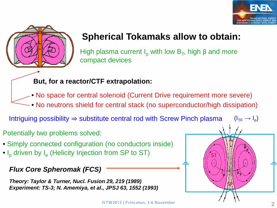
Spherical Tokamaks allow to obtain: High plasma current Ip with low BT, high β and more compact devices
But, for a reactor/CTF extrapolation:
• No space for central solenoid (Current Drive requirement more severe) • No neutrons shield for central stack (no superconductor/high dissipation)
Intriguing possibility ⇒ substitute central rod with Screw Pinch plasma (ITF → Ie)
Potentially two problems solved: • Simply connected configuration (no conductors inside) • Ip driven by Ie (Helicity Injection from SP to ST)
Flux Core Spheromak (FCS) Theory: Taylor & Turner, Nucl. Fusion 29, 219 (1989) Experiment: TS-3; N. Amemiya, et al., JPSJ 63, 1552 (1993)
2
IS TW2015 | P rinceton, 3-6 November
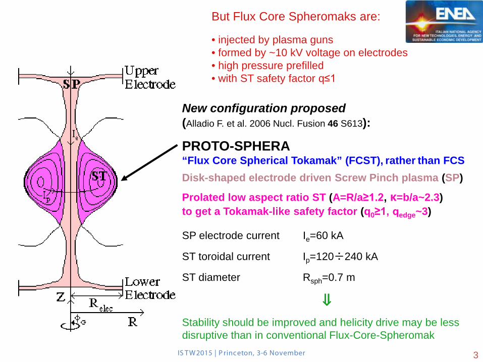
New configuration proposed (Alladio F. et al. 2006 Nucl. Fusion 46 S613):
PROTO-SPHERA “Flux Core Spherical Tokamak” (FCST), rather than FCS
Disk-shaped electrode driven Screw Pinch plasma (SP)
Prolated low aspect ratio ST (A=R/a≥1.2, κ=b/a~2.3) to get a Tokamak-like safety factor (q0≥1, qedge~3)
SP electrode current Ie=60 kA
ST toroidal current Ip=120÷240 kA
ST diameter Rsph=0.7 m
⇓
Stability should be improved and helicity drive may be less disruptive than in conventional Flux-Core-Spheromak
3
But Flux Core Spheromaks are: • injected by plasma guns • formed by ~10 kV voltage on electrodes • high pressure prefilled • with ST safety factor q≤1
IS TW2015 | P rinceton, 3-6 November 4
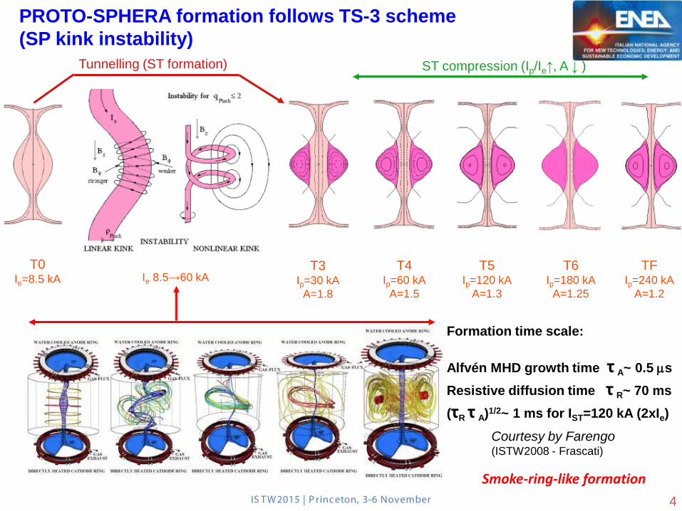
PROTO-SPHERA formation follows TS-3 scheme (SP kink instability)
T0 Ie=8.5 kA Ie 8.5→60 kA
T3 Ip=30 kA
A=1.8
T4 Ip=60 kA
A=1.5
T5 Ip=120 kA
A=1.3
T6 Ip=180 kA
A=1.25
TF Ip=240 kA
A=1.2
Tunnelling (ST formation) ST compression (Ip/Ie↑, A ↓ )
Courtesy by Farengo (ISTW2008 - Frascati)
Smoke-ring-like formation
Formation time scale: Alfvén MHD growth time τ A~ 0.5 µs Resistive diffusion time τ R~ 70 ms (τR τ A)1/2~ 1 ms for IST=120 kA (2xIe)
IS TW2015 | P rinceton, 3-6 November 5
• Stable Screw Pinch formed at Tokamak pressures (10-3÷10-2 mbar) and with low voltage break-down (100-200 V) • Ip/Ie ratio relevant parameter (strong energy dissipation in SP) • MHD equilibria computed both with monotonic as well as reversal safety factor profiles ⇓ magnetic configutation is quite robust
Some level of low n resistive instability needed (reconnections to inject helicity from SP to ST)
but SP+ST must be ideally stable at any time slice
⇓
Ideal MHD analisys to assess Ip/Ie & β limits
(Micozzi P. et al., 2010 Nucl. Fusion 50 095004) ⇓
• Stable at β 21÷26% for Ip/Ie=0.5, down to 14÷16% for Ip/Ie=4 Comparing with the conventional Spherical Tokamak with central rod: βT0=28÷29% for Ip/Ie=0.5 to βT0=72÷84% for Ip/Ie=4 • Spherical Torus elongation κ plays a key role in increasing Ip/Ie • Comparison with TS-3 experimental results: disk-shaped SP plasma important for the configuration stability
Key points of PROTO-SPHERA design
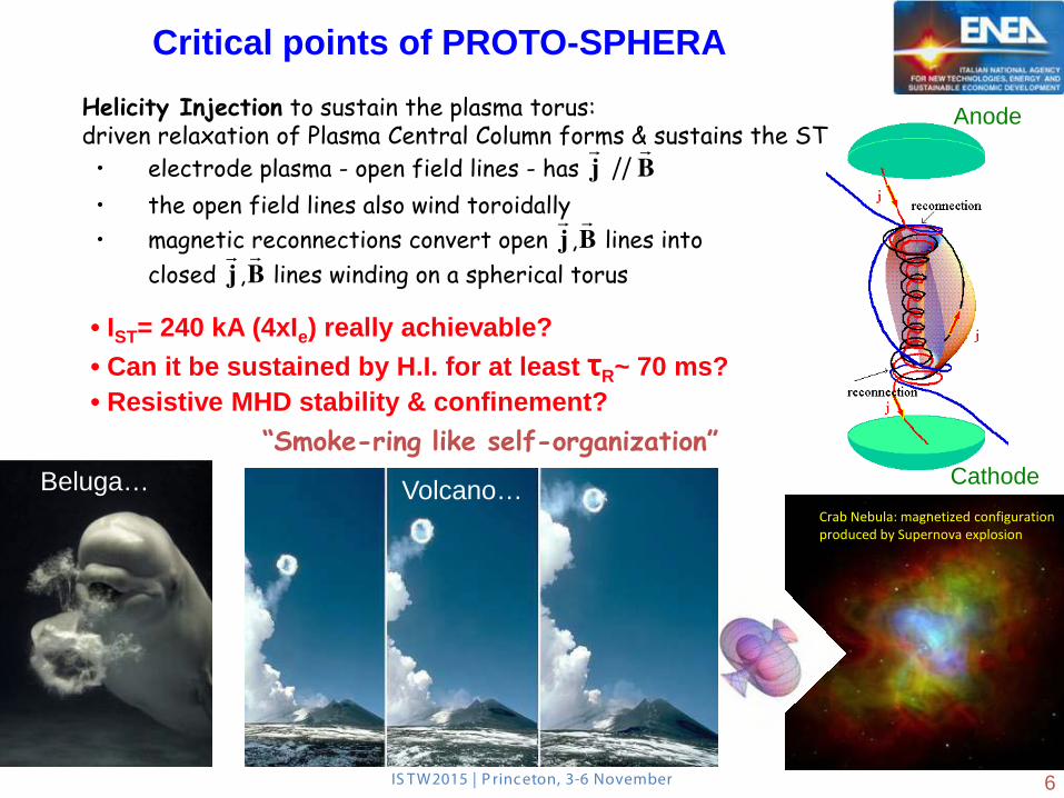
• electrode plasma - open field lines - has
j ||
B
• the open field lines also wind toroidally • magnetic reconnections convert open
j ,
B lines into closed
j ,
B lines winding on a spherical torus
Helicity Injection to sustain the plasma torus: driven relaxation of Plasma Central Column forms & sustains the ST
“Smoke-ring like self-organization”
Anode
Cathode
• IST= 240 kA (4xIe) really achievable? • Can it be sustained by H.I. for at least τR~ 70 ms? • Resistive MHD stability & confinement?
IS TW2015 | P rinceton, 3-6 November
Critical points of PROTO-SPHERA
6
Beluga… Crab Nebula: magnetized configuration produced by Supernova explosion
Volcano…
IS TW2015 | P rinceton, 3-6 November
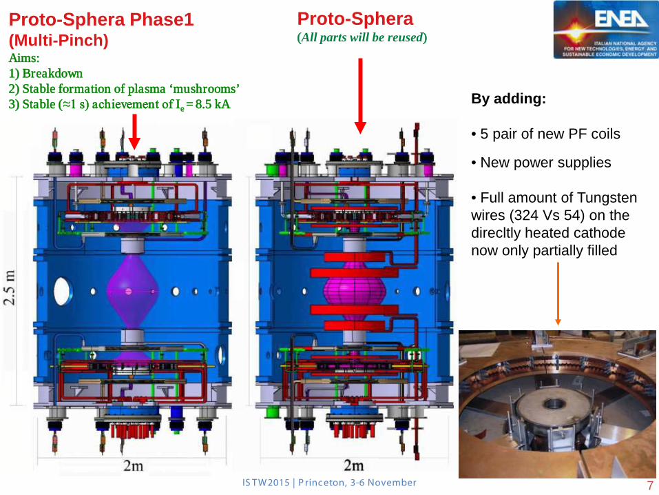
Proto-Sphera Phase1 (Multi-Pinch) Aims: 1) Breakdown 2) Stable formation of plasma ‘mushrooms’ 3) Stable (≈1 s) achievement of Ie = 8.5 kA
Proto-Sphera (All parts will be reused)
By adding: • 5 pair of new PF coils
• New power supplies
• Full amount of Tungsten wires (324 Vs 54) on the direcltly heated cathode now only partially filled
7
IS TW2015 | P rinceton, 3-6 November
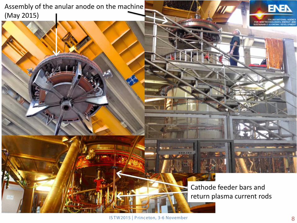
Assembly of the anular anode on the machine (May 2015)
Cathode feeder bars and return plasma current rods
8
IS TW2015 | P rinceton, 3-6 November
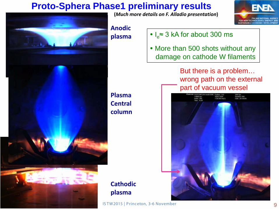
Proto-Sphera Phase1 preliminary results
Anodic plasma
Cathodic plasma
Ie≈ 3 kA for about 300 ms
More than 500 shots without any damage on cathode W filaments
Plasma Central column
But there is a problem… wrong path on the external part of vacuum vessel
9
(Much more details on F. Alladio presentation)
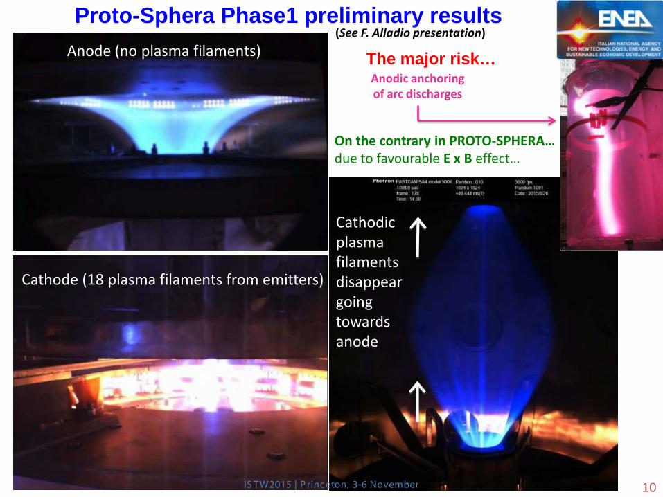
Proto-Sphera Phase1 preliminary results Anode (no plasma filaments)
Cathode (18 plasma filaments from emitters)
Cathodic plasma filaments disappear going towards anode
Anodic anchoring of arc discharges
On the contrary in PROTO-SPHERA… due to favourable E x B effect…
IS TW2015 | P rinceton, 3-6 November 10
The major risk… (See F. Alladio presentation)
IS TW2015 | P rinceton, 3-6 November
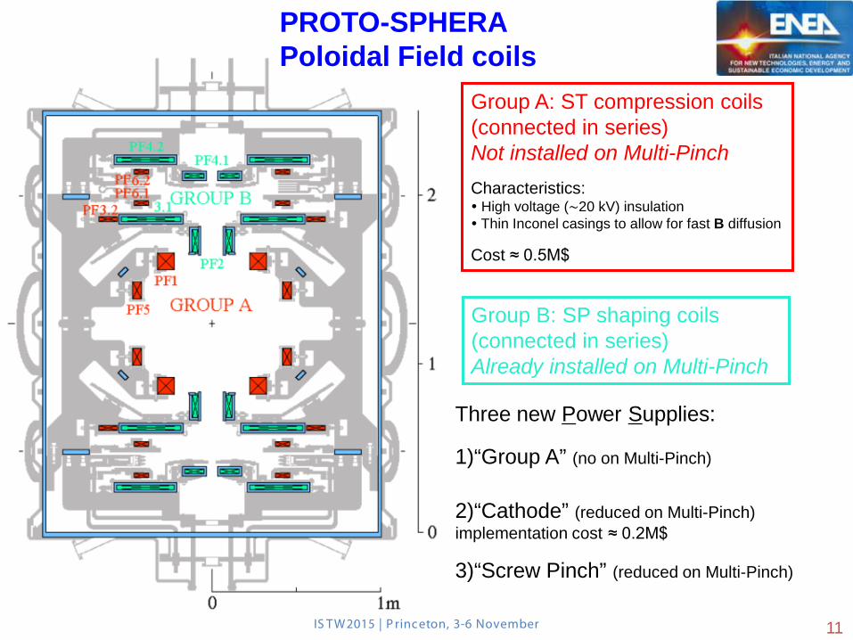
Group A: ST compression coils (connected in series)
Not installed on Multi-Pinch
Characteristics: High voltage (∼20 kV) insulation Thin Inconel casings to allow for fast B diffusion
Cost ≈ 0.5M$
Group B: SP shaping coils (connected in series)
Already installed on Multi-Pinch
Three new Power Supplies:
1)“Group A” (no on Multi-Pinch)
2)“Cathode” (reduced on Multi-Pinch) implementation cost ≈ 0.2M$
3)“Screw Pinch” (reduced on Multi-Pinch)
11
PROTO-SPHERA Poloidal Field coils
IS TW2015 | P rinceton, 3-6 November
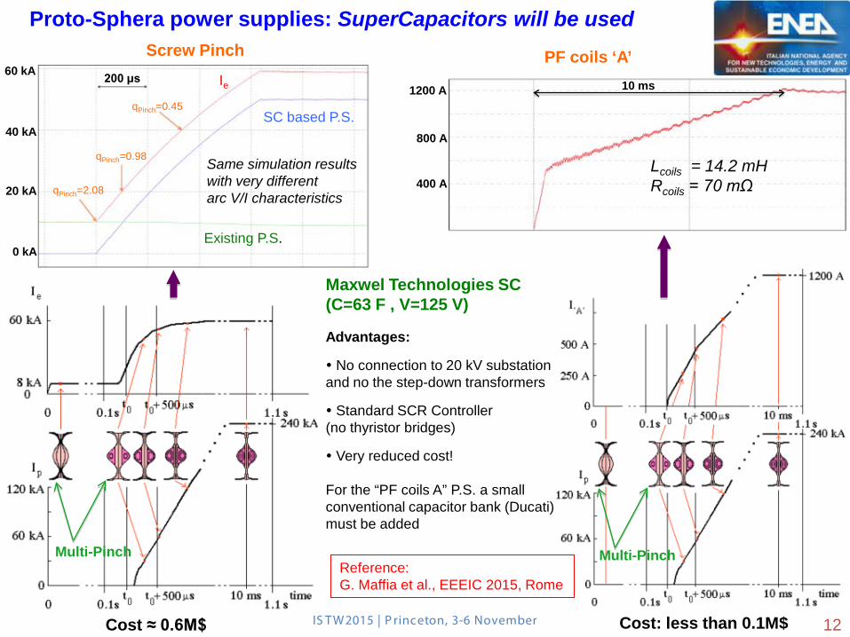
Proto-Sphera power supplies: SuperCapacitors will be used
Multi-Pinch Multi-Pinch
Maxwel Technologies SC (C=63 F , V=125 V) Advantages:
No connection to 20 kV substation and no the step-down transformers
Standard SCR Controller (no thyristor bridges)
Very reduced cost! For the “PF coils A” P.S. a small conventional capacitor bank (Ducati) must be added
12 Cost ≈ 0.6M$ Cost: less than 0.1M$
Screw Pinch PF coils ‘A’
Reference: G. Maffia et al., EEEIC 2015, Rome
qPinch=0.45
qPinch=0.98
qPinch=2.08
200 μs
Same simulation results with very different arc V/I characteristics
60 kA
40 kA
Existing P.S.
SC based P.S.
Ie
20 kA
0 kA
10 ms 1200 A
800 A
400 A Lcoils = 14.2 mH Rcoils = 70 mΩ
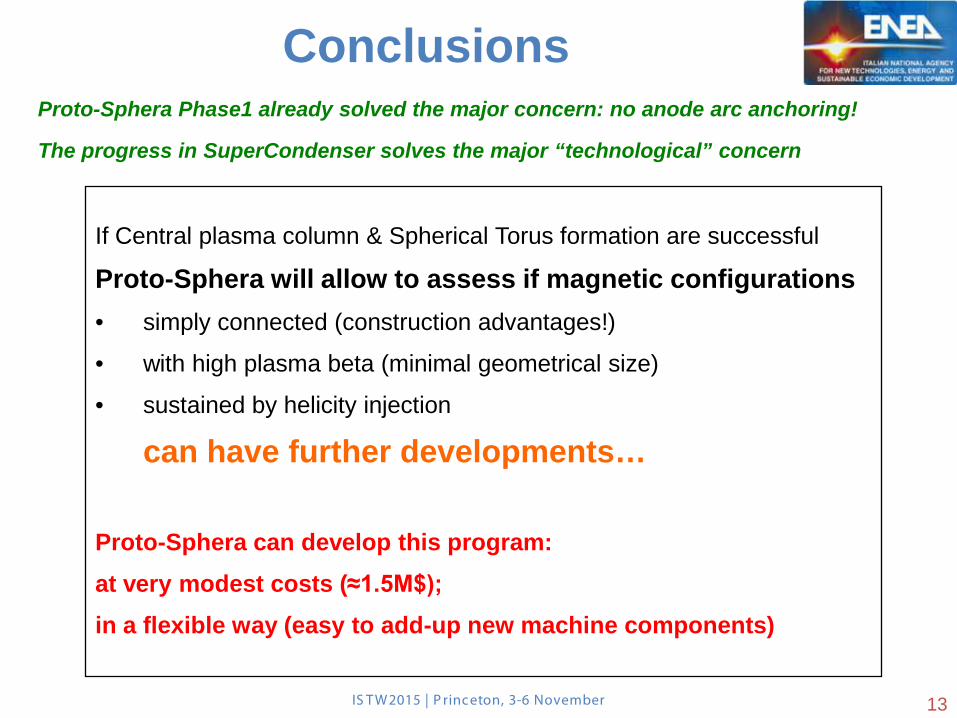
If Central plasma column & Spherical Torus formation are successful
Proto-Sphera will allow to assess if magnetic configurations
• simply connected (construction advantages!)
• with high plasma beta (minimal geometrical size)
• sustained by helicity injection
can have further developments… Proto-Sphera can develop this program:
at very modest costs (≈1.5M$);
in a flexible way (easy to add-up new machine components)
Conclusions
IS TW2015 | P rinceton, 3-6 November
Proto-Sphera Phase1 already solved the major concern: no anode arc anchoring!
The progress in SuperCondenser solves the major “technological” concern
13
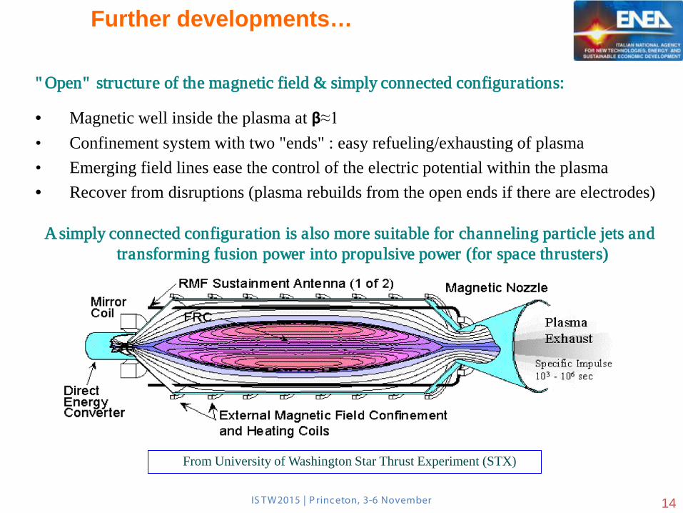
" Open" structure of the magnetic field & simply connected configurations:
• Magnetic well inside the plasma at β≈1 • Confinement system with two "ends" : easy refueling/exhausting of plasma • Emerging field lines ease the control of the electric potential within the plasma • Recover from disruptions (plasma rebuilds from the open ends if there are electrodes)
A simply connected configuration is also more suitable for channeling particle jets and transforming fusion power into propulsive power (for space thrusters)
From University of Washington Star Thrust Experiment (STX)
IS TW2015 | P rinceton, 3-6 November
Further developments…
14
IS TW2015 | P rinceton, 3-6 November
Further developments…
15
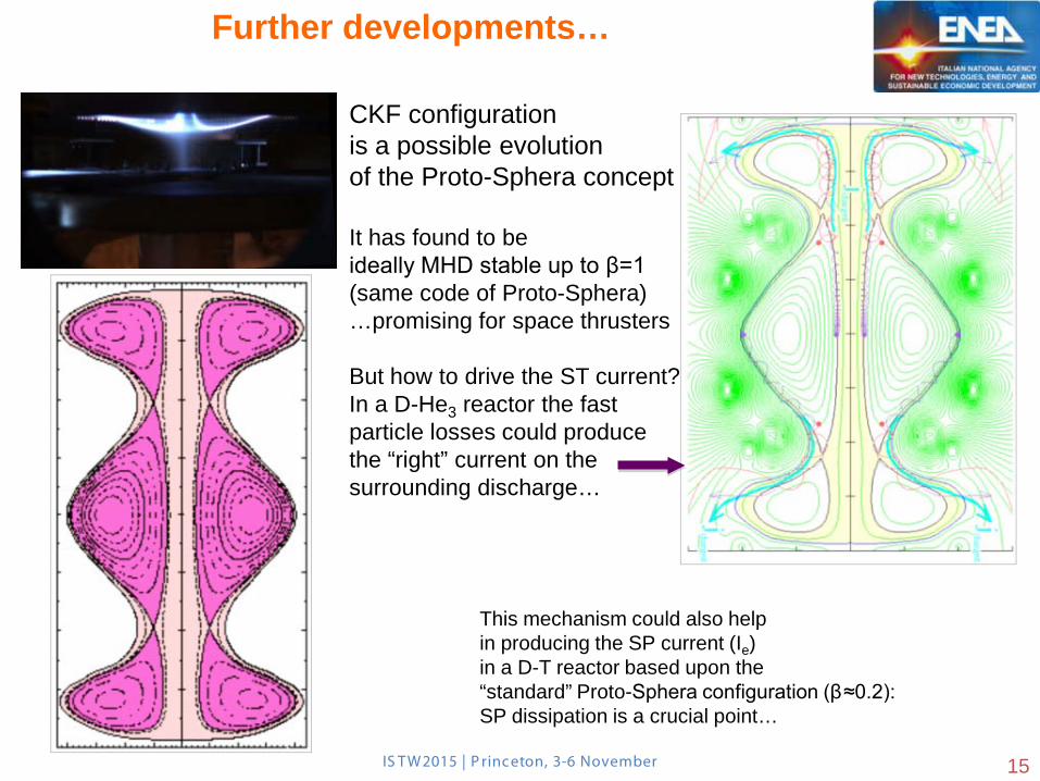
CKF configuration is a possible evolution of the Proto-Sphera concept It has found to be ideally MHD stable up to β=1 (same code of Proto-Sphera) …promising for space thrusters But how to drive the ST current? In a D-He3 reactor the fast particle losses could produce the “right” current on the surrounding discharge…
This mechanism could also help in producing the SP current (Ie) in a D-T reactor based upon the “standard” Proto-Sphera configuration (β≈0.2): SP dissipation is a crucial point…
IS TW2015 | P rinceton, 3-6 November
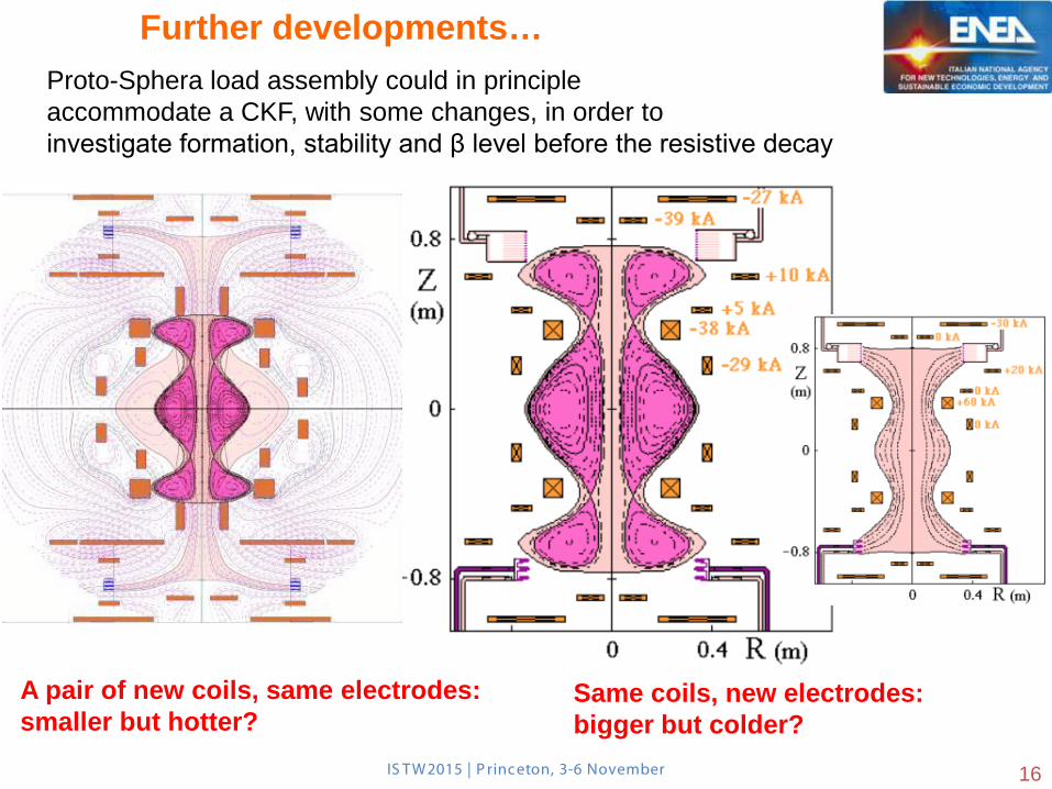
A pair of new coils, same electrodes: smaller but hotter?
Proto-Sphera load assembly could in principle accommodate a CKF, with some changes, in order to investigate formation, stability and β level before the resistive decay
Same coils, new electrodes: bigger but colder?
Further developments…
16


![50 IChO 2018 - pianetachimica.it · oΔG = ΔG + RT lnQ Quoziente di reazione Q Per la reazione a A + b B ⇌ c C + d D: Q = [C]c[D]d [A]a[B]b Variazione di entropia: rev ΔS = q](https://static.fdocument.org/doc/165x107/5c6a38b109d3f2310b8c475f/50-icho-2018-og-g-rt-lnq-quoziente-di-reazione-q-per-la-reazione-a.jpg)