M E 352 - Machine Desiign I Student Summer Semester 2013 E ... · ester 2013 PEN BOOK k paper pro...
34
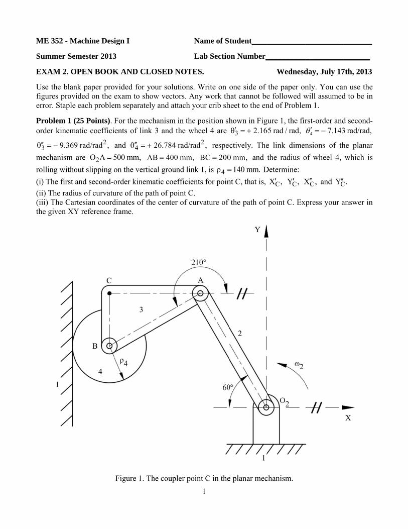
M S E U f e P o θ m r ( ( ( t ME 352 - M Summer Sem EXAM 2. O Use the blan figures provi error. Staple Problem 1 ( order kinema 3 9.369 ′′ θ =− mechanism a rolling witho (i) The first a (ii) The radiu (iii) The Car the given XY Machine Desi mester 2013 OPEN BOOK nk paper pro ided on the e each proble 25 Points). F atic coeffici 2 9 rad/rad , are 2 OA 5 = out slipping o and second-o us of curvatu rtesian coord Y reference f ign I 3 K AND CLO vided for yo exam to sho m separately For the mech ents of link and 4 ′′ θ =+ 500 mm, A on the vertic order kinema ure of the pa dinates of the frame. Figure 1. Th OSED NOT our solutions ow vectors. A y and attach hanism in th 3 and the w 26.784 rad/r B 400 mm = cal ground lin atic coefficie ath of point C e center of c he coupler p 1 Name of S Lab Sectio TES. s. Write on Any work th your crib sh he position sh wheel 4 are 2 rad , respe m, BC 200 = nk 1, is 4 ρ = ents for poin C. curvature of oint C in the Student____ on Number_ one side of hat cannot be heet to the en hown in Fig 3 2.16 ′ θ =+ ectively. The 0 mm, and t 140 mm. = D nt C, that is, the path of e planar mec ___________ __________ Wednesd the paper on e followed w nd of Problem gure 1, the fir 65 rad / rad, e link dimen the radius o Determine: C X , ′ C Y, ′ X point C. Ex chanism. __________ ___________ day, July 17 nly. You can will assumed m 1. rst-order and 4 7.143 θ ′=− nsions of th of wheel 4, C X , ′′ and C Y′ ′ xpress your a ________ _______ 7th, 2013 n use the d to be in d second- 3 rad/rad, he planar which is C . answer in
Transcript of M E 352 - Machine Desiign I Student Summer Semester 2013 E ... · ester 2013 PEN BOOK k paper pro...
M S
E Ufe Po
θmr(((t
ME 352 - M
Summer Sem
EXAM 2. O
Use the blanfigures provierror. Staple
Problem 1 (order kinema
3 9.369′′θ = −mechanism arolling witho(i) The first a(ii) The radiu(iii) The Carthe given XY
Machine Desi
mester 2013
OPEN BOOK
nk paper proided on the eeach proble
25 Points). Fatic coeffici
29 rad/rad , are 2O A 5=
out slipping oand second-ous of curvaturtesian coordY reference f
ign I
3
K AND CLO
vided for yoexam to shom separately
For the mechents of link
and 4′′θ = +500 mm, Aon the verticorder kinemaure of the padinates of theframe.
Figure 1. Th
OSED NOT
our solutionsow vectors. Ay and attach
hanism in th3 and the w
26.784 rad/rB 400 mm=
cal ground linatic coefficie
ath of point Ce center of c
he coupler p1
Name of S
Lab Sectio
TES.
s. Write on Any work thyour crib sh
he position shwheel 4 are
2rad , respem, BC 200=
nk 1, is 4ρ =ents for poin
C. curvature of
oint C in the
Student____
on Number_
one side of hat cannot beheet to the en
hown in Fig3 2.16′θ = +
ectively. The0 mm, and t
140 mm.= Dnt C, that is,
f the path of
e planar mec
___________
__________
Wednesd
the paper one followed wnd of Problem
gure 1, the fir65 rad / rad,
e link dimenthe radius o
Determine:
CX ,′ CY ,′ X
point C. Ex
chanism.
__________
___________
day, July 17
nly. You canwill assumedm 1.
rst-order and4 7.143θ ′ = −
nsions of thof wheel 4,
CX ,′′ and CY′′
xpress your a
________
_______
7th, 2013
n use the d to be in
d second-3 rad/rad,
he planar which is
C.
answer in
M S Prfd
((a((
ME 352 - M
Summer Sem
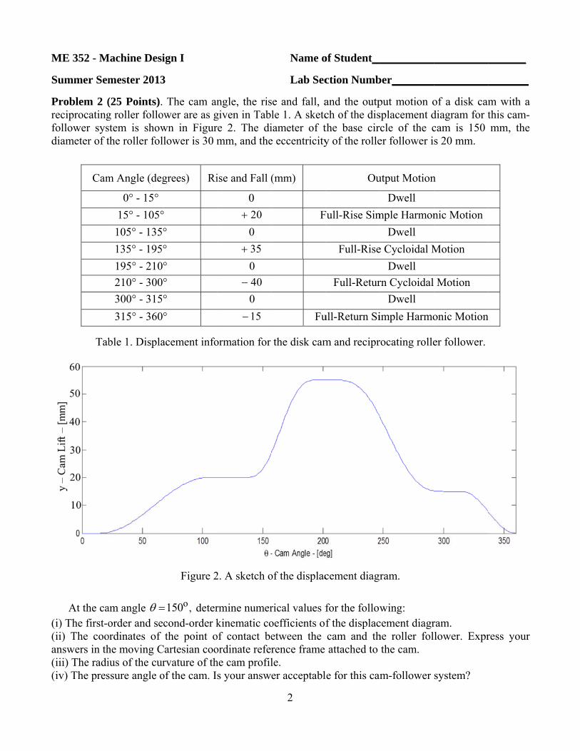
Problem 2 (reciprocatingfollower sysdiameter of t
Cam
Tab
At the ca(i) The first-o(ii) The cooanswers in th(iii) The radi(iv) The pres
Machine Desi
mester 2013
(25 Points).g roller follostem is showthe roller fol
m Angle (deg
0° - 15° 15° - 105°
105° - 135135° - 195195° - 210210° - 300300° - 315315° - 360
ble 1. Displa
am angle θ =order and se
ordinates of he moving Cius of the curssure angle o
ign I
3
The cam anower are as gwn in Figurllower is 30 m
grees) Ri
° ° ° ° ° ° °
acement info
Figure 2
o,150= detercond-order kthe point o
Cartesian coorvature of th
of the cam. I
ngle, the risgiven in Tabre 2. The dimm, and the
ise and Fall (
0 20+
0 35+
0 40−0 15−
ormation for
2. A sketch o
rmine numerkinematic co
of contact beordinate referhe cam profils your answ
2
Name o
Lab Sec
se and fall, ale 1. A sketciameter of te eccentricity
(mm)
F
Fu
the disk cam
of the displac
rical values foefficients ofetween the rence frame le. er acceptabl
of Student__
ction Numb
and the outpch of the disthe base ciry of the rolle
Ou
Full-Rise Sim
Full-Rise
Full-Retur
ull-Return Si
m and recipr
cement diagr
for the followf the displaccam and thattached to
le for this cam
__________
ber________
put motion osplacement drcle of the cer follower i
utput Motion
Dwell mple Harmon
Dwell e Cycloidal M
Dwell rn Cycloidal
Dwell imple Harmo
rocating rolle
ram.
wing: cement diagrhe roller folthe cam.
m-follower
___________
__________
of a disk camdiagram for tcam is 150 s 20 mm.
n
nic Motion
Motion
Motion
onic Motion
er follower.
ram. lower. Expr
system?
_______
________
m with a this cam-mm, the
n
ress your

M S Pv
α
Tom
Il(d((
ME 352 - M
Summer Sem
Problem 3 velocity of
3 110.8α = −
The radius oon link 2 is moments of
2GI 0.105=
link 2 and th(i) Draw thediagram and (ii) Determin(iii) Determi
Machine Desi
mester 2013
(25 Points)the input
25 k rad/sec
of the wheel 75 NCF i=
f inertia of l2N ms , and
e wheel is roe free body d
list all the une the torquene the coeffi
ign I
3
. For the mlink 2 is
, and the acc
is 3 5 mmρ =
N and there link 2 and
d 3GI 0.22=
olling withoudiagrams forunknown vare acting on lificient of fric
mechanism ins 2 2 kω =
celeration of
m, 2 3O G =
is an unknothe wheel a
225 N m s . Tut slipping or links 2 andriables. ink 2. Give tction between
Figure 3. A3
Name o
Lab Sec
n the positiorad / s, the
f the center o
20 mm, andown torque about their m
The pin at theon the groundd 3. Write th
the magnitudn the wheel
A planar mech
of Student__
ction Numb
on shown ine angular
of mass of w
d 2O C 35 m=
12T acting omass center
e center of td link. he three sca
de and the diand the grou
hanism.
__________
ber________
n Figure 3, acceleration
wheel 3 is A
mm. The foon link 2. Trs are 2m =
the wheel is
alar equation
irection of thund.
___________
__________
the constantn of the w
3GA 0.55= +
orce acting aThe masses a
15 kg,= 3m
sliding in th
ns for each f
his vector.
_______
________
t angular wheel is
2i m / s .
at point C and mass
25 kg,=
he slot in
free body
M
S Piei
a((((
ME 352 - M
Summer Sem
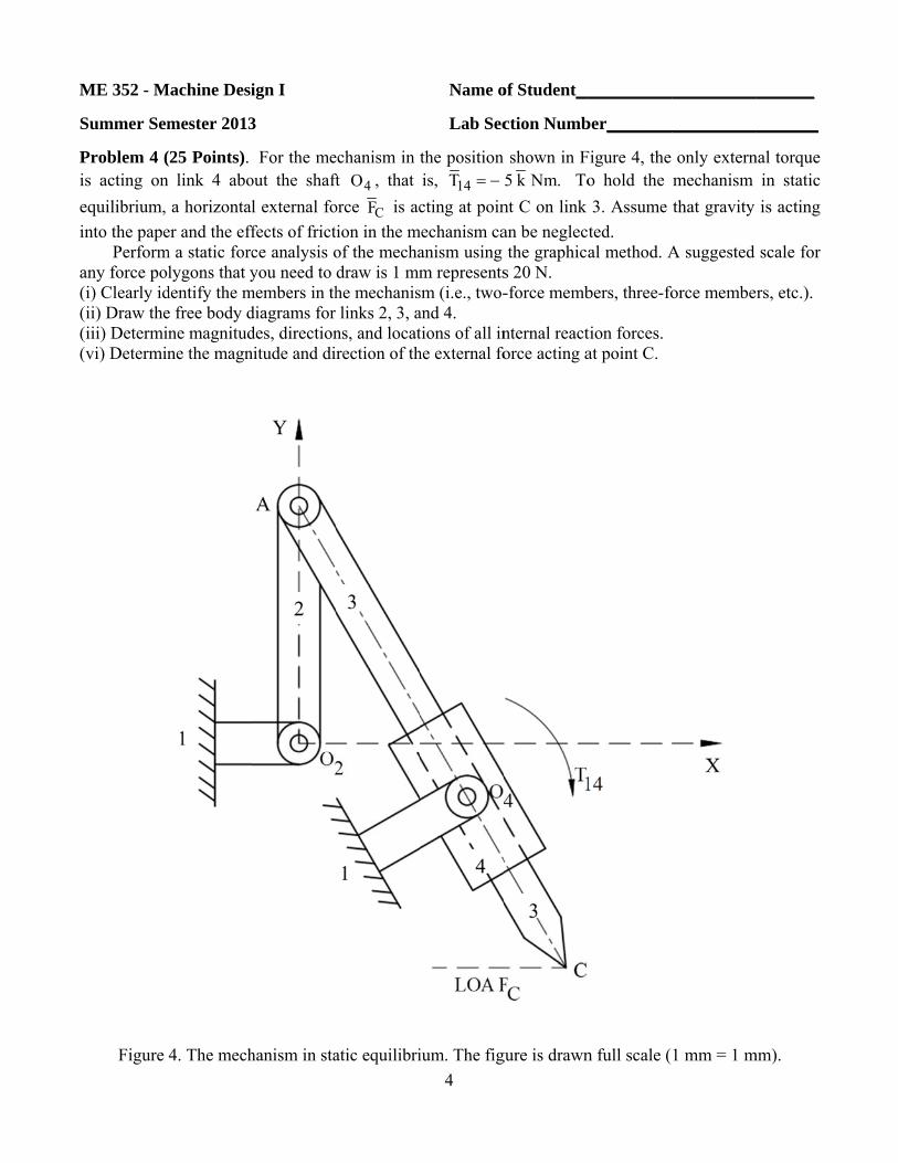
Problem 4 (s acting on
equilibrium, nto the pape
Performany force po(i) Clearly id(ii) Draw the(iii) Determi(vi) Determin
Figure
Machine Desi
mester 2013
(25 Points). n link 4 abo
a horizontaler and the eff
m a static forclygons that y
dentify the me free body dne magnitudne the magn
4. The mech
ign I
3
For the meout the shaftl external fofects of frictce analysis oyou need to
members in thdiagrams for des, directionnitude and di
hanism in sta
echanism in ft 4O , that orce CF is action in the mof the mechadraw is 1 mmhe mechanislinks 2, 3, a
ns, and locatrection of th
atic equilibri4
Name o
Lab Sec
the position is, 14T = −cting at poin
mechanism caanism using m representssm (i.e., two-and 4. tions of all inhe external fo
ium. The fig
of Student__
ction Numb
shown in F5 k Nm. To
nt C on link an be neglecthe graphica
s 20 N. -force memb
nternal reactorce acting a
gure is drawn
__________
ber________
Figure 4, the o hold the 3. Assume ted. al method. A
bers, three-fo
tion forces. at point C.
n full scale (
___________
__________
only externmechanism that gravity
A suggested
orce membe
1 mm = 1 m
_______
________
nal torque in static is acting
scale for
rs, etc.).
mm).
S(
T
w
a
T
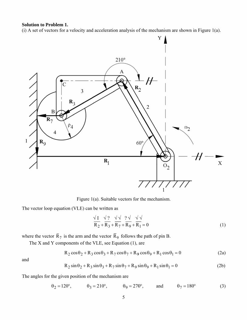
Solution to P(i) A set of v
The vector lo
where the veThe X an
and
The angles fo
Problem 1. vectors for a
oop equation
ector 7R is tnd Y compon
2R
2R
for the given
2 120θ = °
velocity and
Figure 1
n (VLE) can
the arm and tnents of the
2 2 3cos Rθ +
2 2 3sin Rθ +
position of t
,° 3θ
d acceleratio
1(a). Suitable
be written a
√ I √ ? √
2 3R R R+ +
the vector RVLE, see Eq
3 3 7cos Rθ +
3 7sin Rθ +
the mechani
210 ,= °
5
n analysis o
e vectors for
as
√ √ ? √ √
7 9R R R+ +
9R follows thquation (1),
7 7 9cos Rθ +
7 9sin R sθ +
ism are
9 270θ =
f the mechan
r the mechan
√
1R 0=
he path of piare
9 9 1cos Rθ +
9 1sin R siθ +
0 ,° and
nism are sho
nism.
in B.
1cos 0θ =
1in 0θ =
d 7θ =
own in Figur
180= °
re 1(a).
(1)
(2a)
(2b)
(3)
6
Differentiating Equations (2) with respect to the input position 2θ gives
2 2 3 3 3 9 9R sin R sin R cos 0′ ′− θ − θ θ + θ = (4a) and
2 2 3 3 3 9 9R cos R cos R sin 0′ ′+ θ + θ θ + θ = (4b) Writing Equations (4) in matrix form gives
3 3 9 3 2 2
3 3 9 9 2 2
R sin cos R sinR cos sin R R cos
′− θ + θ θ + θ⎡ ⎤ ⎡ ⎤ ⎡ ⎤=⎢ ⎥ ⎢ ⎥ ⎢ ⎥′+ θ + θ − θ⎣ ⎦⎣ ⎦ ⎣ ⎦
(5)
Substituting the known data into Equation (5) gives
3
9
400sin(210 ) mm cos(270 ) rad 500sin(120 ) mmR400cos(210 ) mm sin(270 ) rad 500cos(120 ) mm′θ− ° ° + °⎡ ⎤⎡ ⎤ ⎡ ⎤
=⎢ ⎥⎢ ⎥ ⎢ ⎥′+ ° ° − °⎣ ⎦ ⎣ ⎦⎣ ⎦ (6a)
which simplifies to
3
9
200 mm 0 rad 433.01 mmR346.41 mm 1 rad 250 mm′θ+ +⎡ ⎤⎡ ⎤ ⎡ ⎤
=⎢ ⎥⎢ ⎥ ⎢ ⎥′− − +⎣ ⎦ ⎣ ⎦⎣ ⎦ (6b)
The determinant of the coefficient matrix in Equation (6b) is
DET ( 200 mm)( 1 rad) 200 mm= + − = − (7a) Using Cramer’s rule, the first-order kinematic coefficient for the angle of link 3 is
3433.01 mm 2.165 rad / rad
200 mm−′θ = = +−
(8)
The positive sign indicates that link 3 is rotating counterclockwise for a counterclockwise rotation of the input link 2.
From Cramer’s rule, the first-order kinematic coefficient for point B is
29
200 250 433.01 346.41 mmR 999.995 mm / rad200 mm
+ × + ×′ = = −−
(9a)
Therefore, the first-order kinematic coefficient for point B is
9R 1.0 m / rad′ = − (9b)
The negative sign indicates that the length of the vector 9R is becoming shorter for a counterclockwise rotation of the input link 2, that is point B is moving downward.
The rolling contact constraint between link 4 and the ground link 1 can be written as
9 4 4 7( )R ρ θ θ± Δ = Δ −Δ (10)
7
The correct sign is positive because as the wheel 4 rotates clockwise the magnitude of the vector 9R becomes shorter. Also, the change in the angular position of the vector 7R is zero, that is, 7 0,θΔ = therefore, Equation (10) can be written as
9 4 4R ρ θ+ Δ = Δ (11)
Differentiating Equation (11) with respect to the input position 2θ gives
9 4 4R ρ θ′ ′+ = (12a) Then rearranging this equation, the first-order kinematic coefficient for link 4 can be written as
94
4
Rθρ′
′ = + (12b)
Substituting Equation (9b) and the radius of link 4 into Equation (12b), the first-order kinematic coefficient for link 4 is
4( 999.995 mm) 7.143 rad/rad
140 mmθ −′ = + = − (13)
The negative sign indicates that link 4 is rotating clockwise as the input link 2 rotates counterclockwise.
Differentiating Equations (4) with respect to the input position θ2 gives
22 2 3 3 3 3 3 3 9 9cos cos sin cos 0R R R Rθ θ θ θ θ θ′ ′′ ′′− − − + = (14a)
and 2
2 2 3 3 3 3 3 3 9 9sin sin cos sin 0R R R Rθ θ θ θ θ θ′ ′′ ′′− − + + = (14b) Then writing Equations (14) in matrix form gives
23 3 9 3 2 2 3 3 3
23 3 9 9 2 2 3 3 3
sin cos cos coscos sin sin sin
R R RR R R R
θ θ θ θ θ θθ θ θ θ θ
′′− ⎡ ′ ⎤+⎡ ⎤ ⎡ ⎤= ⎢ ⎥⎢ ⎥ ⎢ ⎥′′ ′+⎣ ⎦ ⎣ ⎦ ⎣ ⎦
(15a)
Substituting the known values into Equation (15a) gives
( )( )
23
29
500cos(120 ) 400cos(210 ) 2.165 mm400sin(210 ) mm cos(270 ) radR400cos(210 ) mm sin(270 ) rad 500sin(120 ) 400sin(210 ) 2.165 mm
⎡ ⎤′′ ° + ° +θ− ° ° ⎡ ⎤⎡ ⎤ ⎢ ⎥=⎢ ⎥⎢ ⎥ ′′+ ° ° ⎢ ⎥⎣ ⎦ ⎣ ⎦ ° + ° +⎣ ⎦ (15b)
which simplifies to
3
9
200 mm 0 rad 1873.70 mmR346.41 mm 1 rad 504.40 mm′′θ+ −⎡ ⎤⎡ ⎤ ⎡ ⎤
=⎢ ⎥⎢ ⎥ ⎢ ⎥′′− − −⎣ ⎦ ⎣ ⎦⎣ ⎦ (15c)
The determinant of the coefficient matrix in Equation (15c) can be written as
200 0200 mm
346.41 1DET
+= = −− −
(16)
Note that the determinant in Equation (16) is the same as the determinant in Equation (7a).
8
Using Cramer’s rule, the second-order kinematic coefficient of link 3 can be written as
2
1873.70 0504.40 1 1873.7 9.3685 rad/rad3 200DET
θ
−− − +′′ = = = −
− (17a)
Similarly, the second-order kinematic coefficient between links 3 and 4 can be written as
29
200 1873.7346.41 504.4 749954.0 3749.77 mm/rad
200R
DET
+ −− − −′′ = = = +
− (17b)
From Equation (12b), the first-order kinematic coefficient for link 4 can be written as
94
4
Rθρ′′
′′ = + (18)
Substituting Equation (17b) and the radius of link 4 into Equation (18), the second-order kinematic coefficient for link 4 is
4( 3749.77 mm) 26.784 rad/rad
140 mmθ +′′ = + = + (19)
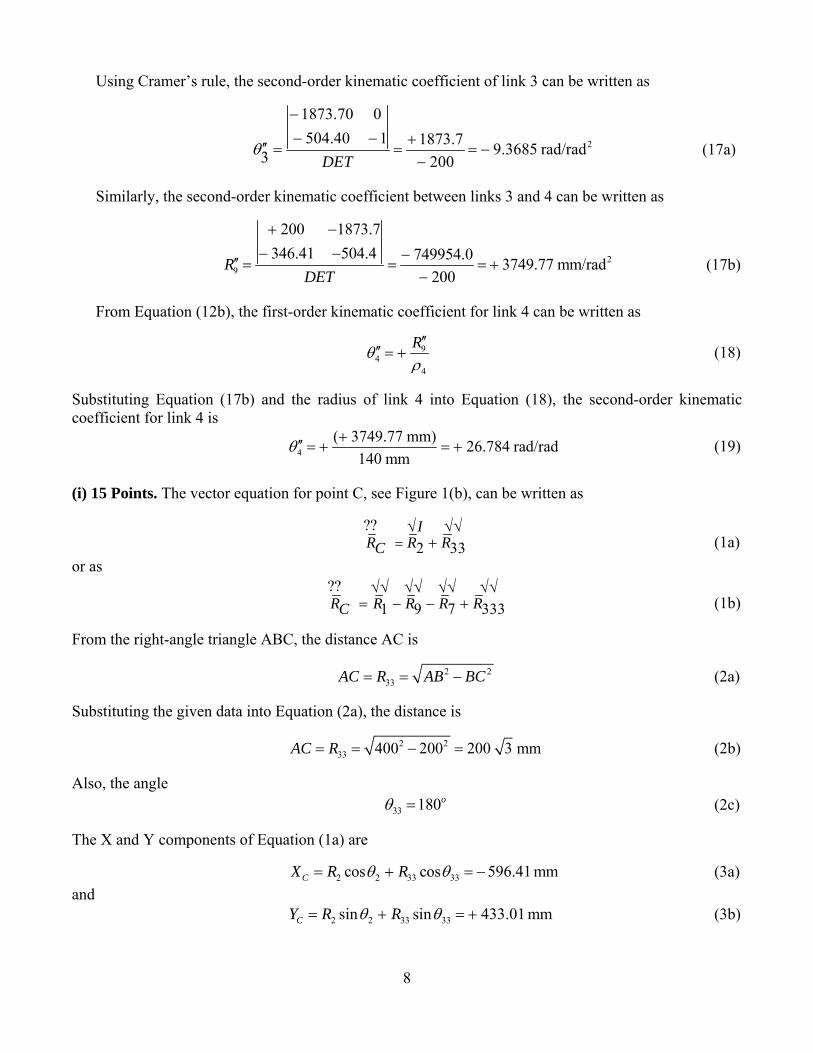
(i) 15 Points. The vector equation for point C, see Figure 1(b), can be written as
??2 33I
R R RC =√ √√
+ (1a) or as
??71 9 333R R R R RC
√√ √√ √√ √√= − − + (1b)
From the right-angle triangle ABC, the distance AC is
2 233AC R AB BC= = − (2a)
Substituting the given data into Equation (2a), the distance is
2 233 400 200 200 3 mmAC R= = − = (2b)
Also, the angle
33 180oθ = (2c) The X and Y components of Equation (1a) are
2 2 33 33cos cos 596.41 mmCX R Rθ θ= + = − (3a) and
2 2 33 33sin sin 433.01 mmCY R Rθ θ= + = + (3b)

Dc
a
Dc
a
(
R
Differentiatincoefficients o
and
Differentiatincoefficients o
and
(iii) 5 points
Recall the de
ng Equationof point C ar
ng Equationof point C ar
CX ′′ =
CY ′′ =
s. The radius
efinition
Fig
ns (3a) and (re
CX ′ =
CY ′ = +
ns (4a) and (4re
2 2cosR θ− −
2 2sinR θ= −
s of curvature
gure 1(b). Th
(3b) with re
2 2sinR θ= − −
2 2cosR θ+ +
4b) with resp
33 33cosR θ θ−
33 33sinR θ θ−
e of the path
Cρ =
CR′ =
9
he vectors fo
espect to the
33 33sinR θ θ−
33 33cosR θ θ+
pect to the i
23 33 sinRθ θ′ −
23 33 cosRθ ′ +
h of point C c
3C
C C C
RX Y Y X
′=
′ ′′ ′−
2C CX Y′± +
or point C.
e input posit
3 433.01θ ′ = −
3 999.98θ ′ = −
input positio
33 3 187θ θ ′′ = +
33 3s 28θ θ ′′ = +
can be writte
CX ′′
2CY ′
tion θ2, the
1 mm/rad
8 mm/rad
on θ2, the sec
73.7 mm/rad
812.5 mm/ra
en as
first-order k
cond-order k
2d
2d
kinematic
(4a)
(4b)
kinematic
(5a)
(5b)
(6)
(7a)

10
where the positive sign must be used here because the input angular velocity is shown as positive in the given figure (that is, counterclockwise). Substituting Equations (4a) and (4b) into Equation (7a) gives
2 2( 433.01) ( 999.98) 1089.7 mmCR′ = + − + − = + (7b)
Substituting Equations (4), (5), and (7b) into Equation (6), the radius of curvature of the path of point C can be written as
3( 1089.7 mm)( 433.01 mm)( 2812.5 mm) ( 999.98 mm)( 1873.7 mm)Cρ
+=
− + − − + (8a)
Therefore, the radius of curvature of the path of point C is
1973.1 mm 1.973 mCρ = + = + (8b) The positive sign indicates that the unit normal vector to the path of point C is pointing towards the center of curvature of the path of point C, see Figure 1(c).
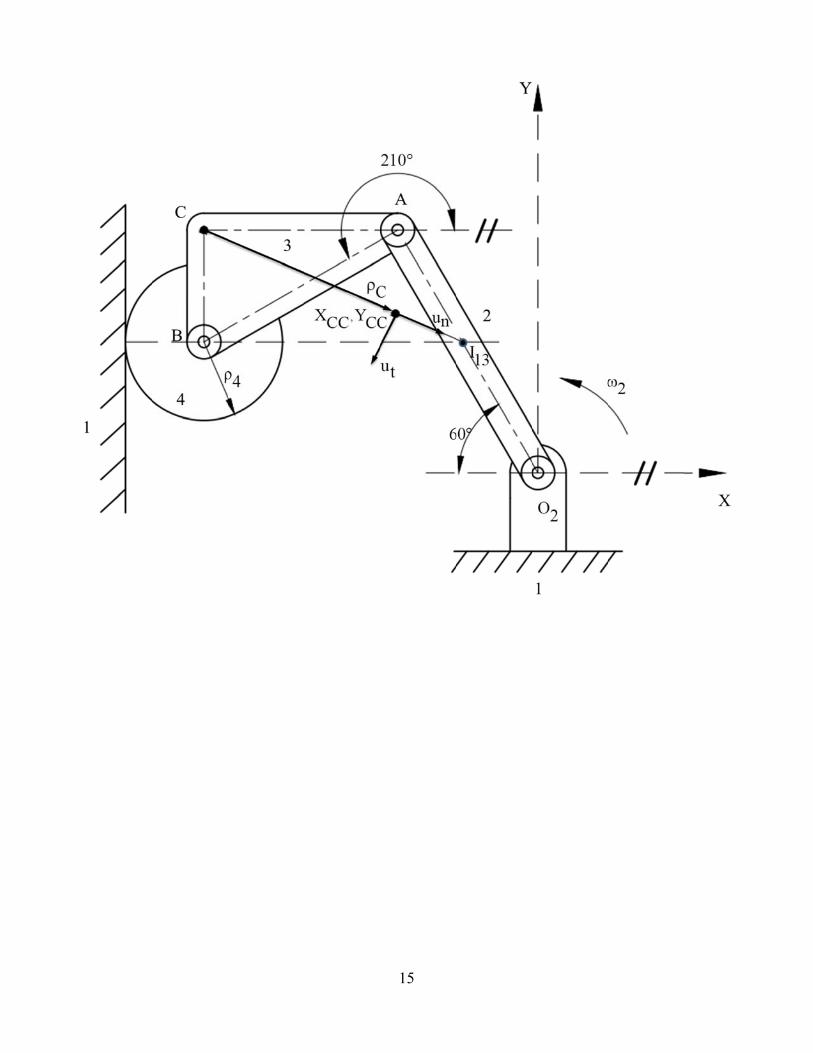
The coordinates of the center of curvature of the path of point C can be written as
CC C
C
YXcc XR
ρ⎡ ⎤′
= − ⎢ ⎥′⎣ ⎦ (9a)
and
CC C
C
XYcc YR
ρ⎡ ⎤′
= + ⎢ ⎥′⎣ ⎦ (9b)
Substituting Equations (2), (4), (5), and (7b) into Equations (9), the coordinates of the center of curvature of the path of point C can be written as
999.98 mm596.41 mm ( 1973.1 mm)1089.7 mm
Xcc⎡ ⎤−
= − − + ⎢ ⎥+⎣ ⎦ (10a)
and 433.01 mm433.01 mm ( 1973.1 mm)1089.7 mm
Ycc⎡ ⎤−
= + + + ⎢ ⎥+⎣ ⎦ (10b)
which can be written as 596.41 mm 1810.65 mmXcc = − + (11a)
and 433.01 mm 784.04 mmYcc = + − (11b)
Therefore, the coordinates of the center of curvature of the path of point C are
1214.2 mm 1.214 mXcc = + = + (12a) and
351.0 mm 0.351 mYcc = − = − (12b) The Cartesian coordinates of the center of curvature of the path of point C are as shown in Figure 1(c).

Figure 11(c). The rad
dius and cent
11
ter of curvatture of the paath of point C.

12
The velocity of point C can be written as
2ˆ ˆV ( )C C CX i Y j ω′ ′= + (5a)
Substituting Equations (3) and the given angular velocity of the input link 2 into Equation (5a), the velocity of point C is
ˆ ˆ ˆ ˆV ( 433.01 mm 999.98 mm )( 50 rad / sec) 21651 49999 mm / secC i j i j= − − + = − − (5b) The magnitude and direction of the velocity of point C are
V 54485 mm/ secC = and V 246.6C∠ = ° (6)
The acceleration of point C can be written as
22 2
ˆ ˆ ˆ ˆA ( ) ( )C C C C CX i Y j X i Y jω α′′ ′′ ′ ′= + + + (7a) Substituting Equations (4) and the given angular velocity and acceleration of the input link 2 into Equation (7a), the acceleration of point C is
2ˆ ˆ ˆ ˆA ( 1873.7 mm 433.01 mm ) ( 50) ( 3678.9 mm 999.98 mm ) (0)C i j i j= + − + + − − (7b) or
2ˆ ˆA 4684300 9197200 mm / secC i j= + − (7c) The magnitude and direction of the acceleration of point C are
2A 10321000 mm/ secB = and A 63.01B∠ = − ° (8)
The unit tangent vector (which points in the direction of the velocity of point C) can be written as ˆ ˆ
ˆ C Ct
C
X i Y juR
′ ′+=
′ (9a)
Recall the definition
2 2C C CR X Y′ ′ ′= ± + (9b)
The positive sign must be used here since the input is positive. Substituting Equations (3a) and (3b) into Equation (9b) gives
2 2( 433.01) ( 999.98) 1089.7 mmCR′ = + − + − = + (9c) The positive sign must be used here because the input angular velocity is counterclockwise.
Substituting Equations (3) and (9b) into Equation (9a), the unit tangent vector is
ˆ ˆ( 433.01) ( 999.98) ˆ ˆˆ 0.397 0.9181089.7ti ju i j− + −
= = − −+
(10)
Check: The unit tangent vector can also be written as

13
VˆV
Ct
C
u = (11a)
Substituting Equations (5b) and (6) into Equation (11a) gives
ˆ ˆ21651 49999 ˆ ˆˆ 0.397 0.91854485t
i ju i j− −= = − − (11b)
The unit normal vector (which is 90° counterclockwise from the unit tangent vector) can be written as
ˆ ˆˆ C C
nC
Y i X juR
′ ′− +=
′ (12a)
Substituting Equations (3) and (9b) into Equation (12a), the unit normal vector is
ˆ ˆˆ 0.918 0.397nu i j= + − (12b) The unit tangent and unit normal vectors to the path of point C are shown in Figure 1(c). The velocity and acceleration vectors of point C are also shown on the figure. Check: Recall that the unit normal vector to the path of point C must pass through the absolute instant center of the coupler link 3 (that is, 13I ), see Figure 1(c).
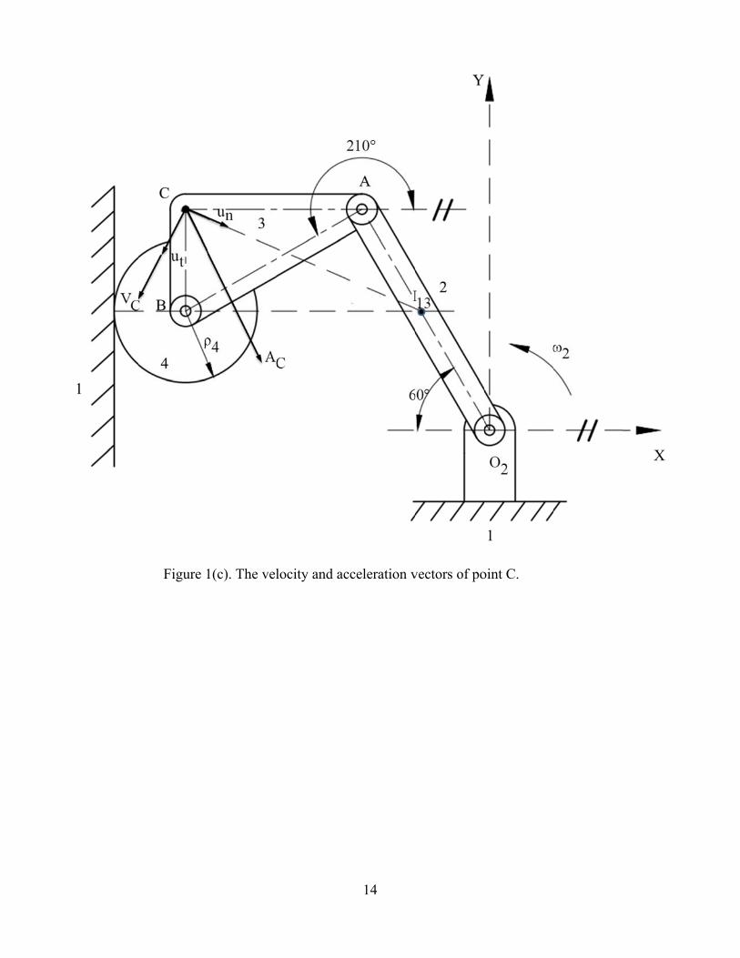
Figure 11(c). The vellocity and ac
14
cceleration vvectors of pooint C.
15
16
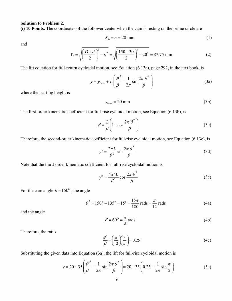
Solution to Problem 2. (i) 10 Points. The coordinates of the follower center when the cam is resting on the prime circle are
0 20 mmX ε= = (1) and
2 22 2
0150 30 20 87.75 mm
2 2D dY ε+ +⎛ ⎞ ⎛ ⎞= − = − =⎜ ⎟ ⎜ ⎟
⎝ ⎠ ⎝ ⎠ (2)
The lift equation for full-return cycloidal motion, see Equation (6.13a), page 292, in the text book, is
* *1 2sin 2basey y L θ π θ
β π β−
⎛ ⎞= + ⎜ ⎟⎜ ⎟
⎝ ⎠ (3a)
where the starting height is
20 mmbasey = (3b) The first-order kinematic coefficient for full-rise cycloidal motion, see Equation (6.13b), is
*2 ' 1 cosLy π θβ β⎛ ⎞
= −⎜ ⎟⎜ ⎟⎝ ⎠
(3c)
Therefore, the second-order kinematic coefficient for full-rise cycloidal motion, see Equation (6.13c), is
2
*2 2 '' sinLy π π θβ β
= (3d)
Note that the third-order kinematic coefficient for full-rise cycloidal motion is
2
3
*4 2 cosLy π π θβ β
′′′ = (3e)
For the cam angle ,150oθ = the angle
* 15150 135 15 rads rads180 12
o o o π πθ = − = = = (4a)
and the angle
360 radso πβ = = (4b)
Therefore, the ratio
* 3 0.2512
θ ππβ
⎛ ⎞⎛ ⎞⎜ ⎟⎜ ⎟⎝ ⎠⎝ ⎠
= = (4c)
Substituting the given data into Equation (3a), the lift for full-rise cycloidal motion is
* *1 2 120 35 sin 20 35 0.25 sin2 2 2
y θ π θ πβ π β π
⎛ ⎞ ⎛ ⎞= + − = + −⎜ ⎟ ⎜ ⎟⎜ ⎟ ⎝ ⎠⎝ ⎠ (5a)
17
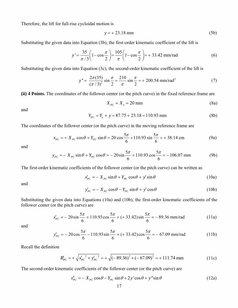
Therefore, the lift for full-rise cycloidal motion is
23.18 mmy = + (5b) Substituting the given data into Equation (3b), the first-order kinematic coefficient of the lift is
35 105 ' 1 cos 1 cos 33.42 mm/rad/ 3 2 2
y π ππ π
⎛ ⎞ ⎛ ⎞= − = − = +⎜ ⎟ ⎜ ⎟⎝ ⎠ ⎝ ⎠
(6)
Substituting the given data into Equation (3c), the second-order kinematic coefficient of the lift is
22
2 (35) 210 '' sin sin 200.54 mm/rad( / 3) 2 2
y π π ππ π
= = = + (7)
(ii) 4 Points. The coordinates of the follower center (or the pitch curve) in the fixed reference frame are
20 mmPC oX X= = (8a) and
87.75 23.18 110.93 mmPC oY Y y= + = + = (8b) The coordinates of the follower center (or the pitch curve) in the moving reference frame are
5 5cos sin 20 cos 110.93 sin 38.14 cm6 6PC PC PCx X Y π πθ θ= + + = + = + (9a)
and 5 5sin cos 20sin 110.93 cos 106.07 mm6 6PC PC PCy X Y π πθ θ= − + = − + = − (9b)
The first-order kinematic coefficients of the follower center (or the pitch curve) can be written as
sin cos sinPC PC PCx X Y yθ θ θ′ ′= − + + (10a) and
cos sin cosPC PC PCy X Y yθ θ θ′ ′= − − + (10b) Substituting the given data into Equations (10a) and (10b), the first-order kinematic coefficients of the follower center (or the pitch curve) are
5 5 520sin 110.93cos ( 33.42)sin 89.36 mm/rad6 6 6PCx π π π′ = − + + + = − (11a)
and 5 5 520cos 110.93sin ( 33.42)cos 67.09 mm/rad6 6 6PCy π π π′ = − − + + = − (11b)
Recall the definition
2 2 2 2( 89.36) ( 67.09) 111.74 mmPC PC PCR x y′ ′ ′= + + = + − + − = + (11c) The second-order kinematic coefficients of the follower center (or the pitch curve) are
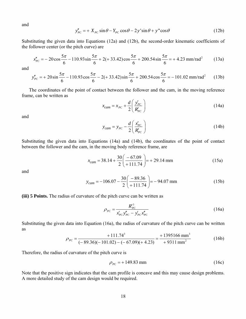
cos sin 2 'cos "sin′′ = − − + +PC PC PCx X Y y yθ θ θ θ (12a)
18
and sin cos 2 'sin "cosPC PC PCy X Y y yθ θ θ θ′′ = + − − + (12b)
Substituting the given data into Equations (12a) and (12b), the second-order kinematic coefficients of the follower center (or the pitch curve) are
25 5 5 520cos 110.93sin 2( 33.42)cos 200.54sin 4.23 mm/rad6 6 6 6PCx π π π π′′ = − − + + + = + (13a)
and 25 5 5 520sin 110.93cos 2( 33.42)sin 200.54cos 101.02 mm/rad
6 6 6 6PCy π π π π′′ = + − − + + = − (13b)
The coordinates of the point of contact between the follower and the cam, in the moving reference frame, can be written as
2PC
PCPC
camydx xR
⎛ ⎞′= + ⎜ ⎟′⎝ ⎠
(14a)
and
2PC
PCPC
camxdy yR
⎛ ⎞′= − ⎜ ⎟′⎝ ⎠
(14b)
Substituting the given data into Equations (14a) and (14b), the coordinates of the point of contact between the follower and the cam, in the moving body reference frame, are
30 67.0938.14 29.14 mm2 111.74camx⎛ ⎞−
= + = +⎜ ⎟+⎝ ⎠ (15a)
and 30 89.36106.07 94.07 mm2 111.74camy⎛ ⎞−
= − − = −⎜ ⎟+⎝ ⎠ (15b)
(iii) 5 Points. The radius of curvature of the pitch curve can be written as
3PC
PCPC PC PC PC
Rx y y x
ρ′
=′ ′′ ′ ′′−
(16a)
Substituting the given data into Equation (16a), the radius of curvature of the pitch curve can be written as
3 3
2
111.74 1395166 mm( 89.36)( 101.02) ( 67.09)( 4.23) 9311 mmPCρ + +
= =− − − − + +
(16b)
Therefore, the radius of curvature of the pitch curve is
149.83 mmPCρ = + (16c)
Note that the positive sign indicates that the cam profile is concave and this may cause design problems. A more detailed study of the cam design would be required.
19
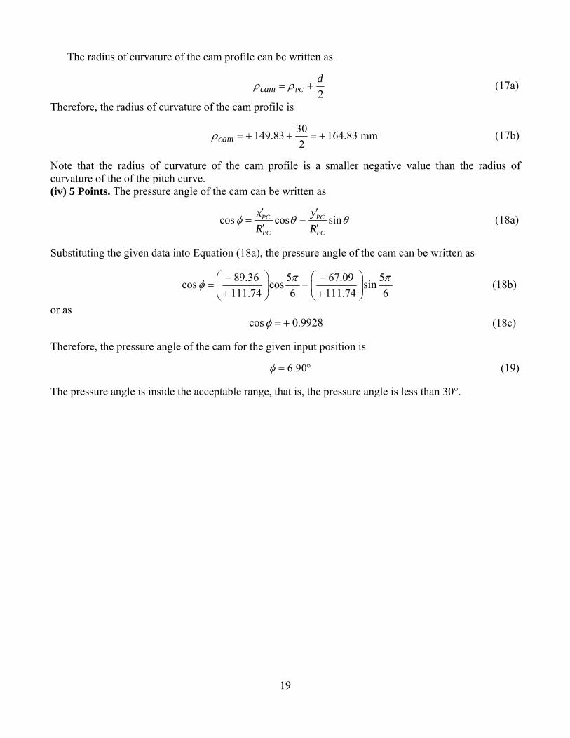
The radius of curvature of the cam profile can be written as
2PCcamdρ ρ= + (17a)
Therefore, the radius of curvature of the cam profile is
30149.83 164.83 mm2camρ = + + = + (17b)
Note that the radius of curvature of the cam profile is a smaller negative value than the radius of curvature of the of the pitch curve. (iv) 5 Points. The pressure angle of the cam can be written as
cos cos sinPC PC
PC PC
x yR R
φ θ θ′ ′
= −′ ′
(18a)
Substituting the given data into Equation (18a), the pressure angle of the cam can be written as
89.36 5 67.09 5cos cos sin111.74 6 111.74 6
π πφ⎛ ⎞ ⎛ ⎞− −
= −⎜ ⎟ ⎜ ⎟+ +⎝ ⎠ ⎝ ⎠ (18b)
or as cos 0.9928φ = + (18c)
Therefore, the pressure angle of the cam for the given input position is
6.90φ = ° (19) The pressure angle is inside the acceptable range, that is, the pressure angle is less than 30°.

S(
T
w
a
T
D
a
Solution to P(i) A set of v
The vector lo
where the ve
and
The angles fo
Differentiatin
and
Problem 3. vectors for a
Figure 3
oop equation
ector 7R is t
for the given
ng Equation
velocity and
3(a). Suitable
n (VLE) can
the arm. The
23R co
23R sin
position of t
23θ = θ
s (2) with re
2R′+
2R′+
d acceleratio
e vectors for
be written a
? I √ C 23 7R R+ −
e X and Y co
23 7s R coθ +
23 7n R sinθ +
the mechani
2 30θ = − °
espect to the
23 23cos Rθ −
23 23sin Rθ +
20
n analysis o
r a kinematic
as
? √ √ √ 9 1R R 0− − =
omponents o
7 9os R coθ −
7 9n R sinθ −
ism are
and
input positio
23 23R sinθ −
23 23R cosθ −
f the mechan
c analysis of
0
f Equation (
9 1os R coθ −
9 1n R sinθ −
θ
on 2θ gives
9 9R cos′− θ =
9 9R sin′− θ =
nism are sho
f the mechan
(1) are
1os 0θ =
1n 0θ =
9 0θ = °
0=
0=
own in Figur
nism.
re 3(a).
(1)
(2a)
(2b)
(3)
(4a)
(4b)
21
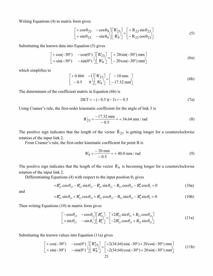
Writing Equations (4) in matrix form gives
23 9 23 23 23
23 9 9 23 23
cos cos R R sinsin sin R R cos
′+ θ − θ + θ⎡ ⎤ ⎡ ⎤ ⎡ ⎤=⎢ ⎥ ⎢ ⎥ ⎢ ⎥′+ θ − θ − θ⎣ ⎦ ⎣ ⎦ ⎣ ⎦
(5)
Substituting the known data into Equation (5) gives
23
9
Rcos( 30 ) cos(0 ) 20sin( 30 ) mmRsin( 30 ) sin(0 ) 20cos( 30 ) mm′+ − ° − ° + − °⎡ ⎤⎡ ⎤ ⎡ ⎤
=⎢ ⎥⎢ ⎥ ⎢ ⎥′+ − ° − ° − − °⎣ ⎦ ⎣ ⎦⎣ ⎦ (6a)
which simplifies to
23
9
R0.866 1 10 mmR0.5 0 17.32 mm′+ − −⎡ ⎤⎡ ⎤ ⎡ ⎤
=⎢ ⎥⎢ ⎥ ⎢ ⎥′− −⎣ ⎦ ⎣ ⎦⎣ ⎦ (6b)
The determinant of the coefficient matrix in Equation (6b) is
DET ( 0.5 )( 1) 0.5= − − − = − (7a) Using Cramer’s rule, the first-order kinematic coefficient for the angle of link 3 is
2317.32 mmR 34.64 mm / rad
0.5−′ = = +
− (8)
The positive sign indicates that the length of the vector 23R is getting longer for a counterclockwise rotation of the input link 2.
From Cramer’s rule, the first-order kinematic coefficient for point B is
920 mmR 40.0 mm / rad
0.5−′ = = +−
(9)
The positive sign indicates that the length of the vector 9R is becoming longer for a counterclockwise rotation of the input link 2.
Differentiating Equations (4) with respect to the input position θ2 gives
23 23 23 23 23 23 23 23 9 9cos sin sin cos cos 0R R R R Rθ θ θ θ θ′′ ′ ′ ′′+ − − − − = (10a) and
23 23 23 23 23 23 23 23 9 9sin cos cos sin sin 0R R R R Rθ θ θ θ θ′′ ′ ′ ′′+ + + − − = (10b) Then writing Equations (10) in matrix form gives
23 9 23 23 23 23 23
23 9 9 23 23 23 23
cos cos 2 sin cossin sin 2 cos sin
R R RR R R
θ θ θ θθ θ θ θ
′′ ′− − + +⎡ ⎤ ⎡ ⎤ ⎡ ⎤=⎢ ⎥ ⎢ ⎥ ⎢ ⎥′′ ′+ − − +⎣ ⎦ ⎣ ⎦ ⎣ ⎦
(11a)
Substituting the known values into Equation (11a) gives
23
9
Rcos( 30 ) cos(0 ) 2(34.64)sin( 30 ) 20cos( 30 ) mmRsin( 30 ) sin(0 ) 2(34.64) cos( 30 ) 20sin( 30 ) mm′′+ − ° − ° + − ° + − °⎡ ⎤⎡ ⎤ ⎡ ⎤
=⎢ ⎥⎢ ⎥ ⎢ ⎥′′+ − ° − ° − − ° + − °⎣ ⎦ ⎣ ⎦⎣ ⎦ (11b)
22
which simplifies to
3
34
0.866 1 17.32 mmR0.5 0 70.00 mm′θ+ − −⎡ ⎤⎡ ⎤ ⎡ ⎤
=⎢ ⎥⎢ ⎥ ⎢ ⎥′− −⎣ ⎦ ⎣ ⎦⎣ ⎦ (12c)
The determinant of the coefficient matrix in Equation (12c) can be written as
DET ( 0.5 )( 1) 0.5= − − − = − (13) Note that the determinant in Equation (13) is the same as the determinant in Equation (7a).
Using Cramer’s rule, the second-order kinematic coefficient of vector R23 can be written as
2
17.32 170 0 70 140 mm/rad23 0.5
RDET
− −− −′′ = = = +
− (14a)
Similarly, the second-order kinematic coefficient of the vector R9 can be written as
29
0.866 17.320.5 70
138.56 mm/radRDET
−− −
′′ = = + (14b) The vector equation for the mass center G3 can be written as
3
?? ?23G
IR R= (15)
The X and Y components of Equation (15) are
3 23 23cosGX R θ= (16a) and
3 23 23sinGY R θ= (16b) Differentiating Equations (16a) and (16b) with respect to the input position θ2, the first-order kinematic coefficients of the mass center G3 are
3 23 23 23 23cos sinGX R Rθ θ′ ′= + − (17a) and
3 23 23 23 23sin cosGY R Rθ θ′ ′= + + (17b) Differentiating Equations (17a) and (17b) with respect to the input position θ2, the second-order kinematic coefficients of the mass center G3 are
3 23 23 23 23 23 23cos 2 sin cosGX R R Rθ θ θ′′ ′′ ′= + − − (18a) and
3 23 23 23 23 23 23sin 2 cos sinGY R R Rθ θ θ′′ ′′ ′= + + − (18b) Substituting Equations (8) and (14a) and the given angular velocity and acceleration of the input link 2 into Equations (18), the second order kinematic coefficients of the mass center G3 are
23
2
3 138.56 mm/radGX ′′ = + and 23 0 mm/radGY ′′ = (19)
The acceleration of the mass center G3 can be written as
2
3 3 3 2 3 3 2ˆ ˆ ˆ ˆA ( ) ( )G G G G GX i Y j X i Y jω α′′ ′′ ′ ′= + + + (20a)
Substituting Equation (19) and the given angular velocity and acceleration of the input link 2 into Equation (20a), the acceleration of the mass center G3 is
23
ˆ ˆA ( 138.56 mm 0 mm ) ( 2) 0G i j= + − + + (20b) or
23
ˆA 554.3 mm / secG i= + (20c)
The rolling contact constraint between link 3 and the ground link 1 can be written as
9 3 3 7( )R ρ θ θ± Δ = Δ −Δ (21) The correct sign is negative because as the wheel 3 rotates counterclockwise the magnitude of the vector
9R becomes shorter. Also, the change in the angular position of the vector 7R is zero, that is, 7 0,θΔ = therefore, Equation (21) can be written as
9 3 3R ρ θ− Δ = Δ (22)
Differentiating Equation (22) with respect to the input position 2θ gives
9 3 3R ρ θ′ ′− = (23a) Then rearranging this equation, the first-order kinematic coefficient for link 3 can be written as
93
3
Rθρ′
′ = − (23b)
Substituting Equation (9) and the radius of link 3 into Equation (23b), the first-order kinematic coefficient for link 3 is
3( 40.0 mm) 8.0 rad/rad
5 mmθ +′ = − = − (24)
The negative sign indicates that link 3 is rotating clockwise as the input link 2 rotates counterclockwise.
From Equation (23b), the second-order kinematic coefficient for link 3 can be written as
93
3
Rθρ′′
′′ = − (25)
Substituting Equation (14b) and the radius of link 3 into Equation (25), the second-order kinematic coefficient for link 3 is
23
( 138.56 mm) 27.71 rad/rad5 mm
θ +′′ = − = − (26)

T
Sl
T2
(
o
S
o
The angular
Substituting link 3 is
The negative2 rotates cou
(i) 5 Points.
The sum
or as
Similarly, th
or as
acceleration
Equation (2
e sign indicaunterclockwi
The free bod
Fig
of the extern
e sum of the
n of link 3 ca
6) and the in
α
ates that the ise.
dy diagram f
gure 3(b). Th
nal forces in
e external for
an be written
nput angular
3 0 ( 2α = + −
angular acce
for link 2 is
he free body
n the X-direc
F∑
12 XF +
rces in the Y
∑
12YF +
24
n as
3 3 2α θ α θ′= +
r velocity int
27.71)( 2)+ =
eleration of
shown in Fi
diagram for
ction can be
2 2X G XF m A=
32 X CF F+ + =
Y-direction c
2 2Y G YF m A=
32 2YF W+ − =
23 2θ ω′′
to Equation
110.85 ra= −
link 3 is rot
igure 3(b).
r link 2.
written as
0=
can be writte
Y
0=
(27), the ang
2ad/sec
tating clockw
n as
gular acceler
wise as the i
(27)
ration for
(28)
input link
(1a)
(1b)
(2a)
(2b)
T
o
Ea
(
o
S
o
The sum of t
or as
Equations (1and Y compo
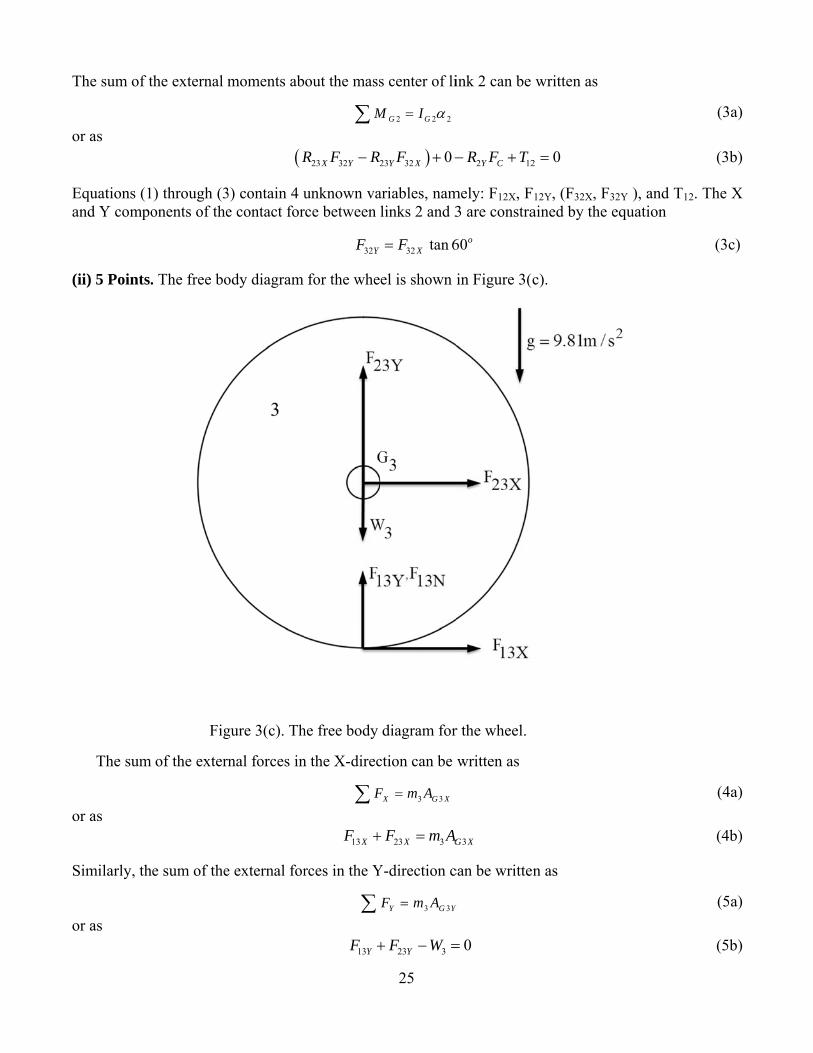
(ii) 5 Points.
The sum
or as
Similarly, th
or as
the external m
) through (3onents of the
. The free bo
Fig
of the extern
e sum of the
moments ab
(R
3) contain 4 ue contact for
ody diagram
gure 3(c). Th
nal forces in
e external for
out the mass
M∑
23 32 2X YR F R−
unknown varce between
32YF
for the whe
he free body
n the X-direc
F∑
13XF +
rces in the Y
∑
13YF +
25
s center of li
2 2 2G GM I α=
)23 32 0Y XF + −
ariables, namlinks 2 and 3
32 tan 6XF=
el is shown i
diagram for
ction can be
3 3X G XF m A=
23 3X GF m A+ =
Y-direction c
3 3Y G YF m A=
23 3YF W+ − =
ink 2 can be
2 12Y CR F T− +
mely: F12X, F3 are constra
60o
in Figure 3(c
r the wheel.
written as
3G X
can be writte
Y
0=
written as
2 0=
F12Y, (F32X, Fained by the
c).
n as
F32Y ), and T1equation
(3a)
(3b)
12. The X
(3c)
(4a)
(4b)
(5a)
(5b)
26
The sum of the external moments about the center of mass of the wheel can be written as
3 3 3G GM I α=∑ (6a) or as
3 13 3 30 Y X GR F I α− = (6b) Equations (4) through (6) contain 2 new unknown variables, namely: the internal forces F13X and F13Y. Therefore, there are a total of 6 equations and 6 unknown variables.
When the two components of the force between the wheel and the ground are obtained then the coefficient of friction between the wheel and the ground can be obtained from the constraint equation
13 13X YF Fμ= (7) (iii) 5 Points. The unknown variables will be obtained from Equations (1) through (7) using the Method of Inspection. The procedure is: (a) Determine the internal force F13X from Equation (6b), that is
3 313
3
GX
Y
IFRα
= − (8a)
Substituting the given data into Equation (8a), the internal force is
2 2
13(0.225 N ms )( 110.85 rad/s ) 4988.25 N
(5 mm) sin( 90 )XF −= − = −
− ° (8b)
(b) Determine the internal force F23X from Equation (4b), that is
23 3 3 13X G X XF m A F= − (9a) Substituting the given data and Equation (8b) into Equation (9a), the internal force is
23 25( 0.55) ( 4988.25) 5002.11 NXF = + − − = + (9b) (c) Determine the Y component of the contact force between links 2 and 3 from Equation (3c), that is
32 32 tan 60oY XF F= (10a)
Substituting Equation (9b) into Equation (10a), the internal force is
32 5002.11 tan 60 8663.90 NoYF = − = − (10b)
(d) Determine the Y component of the contact force between links 1 and 2 from Equation (2b), that is
12 2 32Y YF W F= − (11a) Substituting Equation (10b) into Equation (11a), the internal force is
12 15(9.81) ( 8663.90) 8811.05 NYF = − − = + (11b) (e) Determine the Y component of the contact force between links 1 and 3 from Equation (5b), that is
27
13 3 23Y YF W F= − (12a) Substituting Equation (10b) into Equation (12a), the internal force is
13 25(9.81) ( 8663.90) 8418.65 NYF = − + = − (12b) (f) Determine the torque acting on the ground link from Equation (3c), that is
( )12 2 23 32 23 32Y C X Y Y XT R F R F R F= − − (13a) Substituting Equation (10b) into Equation (12a), the torque acting on the ground link is
( )12 0.035sin( 30 ) 0.02cos( 30 )( 8663.90) 0.02sin( 30 )( 5002.11) 186.96 NmT = − ° − − ° − − − ° − = + (13b) (iv) 5 Points. The coefficient of friction between the wheel and the ground from Equation (7), can be written as
13
13
X
Y
FF
μ = (14a)
Substituting Equation (8b) and (12a) into Equation (14a), the coefficient of friction between the wheel and the ground link is
4998.25 0.598418.65
μ −= =−
(14b)
S( S((( S
(oNo
oftcdt
Solution to P(i) 6 Points.
Step I. Identi(i) Link 2 is (iii) Link 3 is(iii) Link 4 h
Step II. Draw
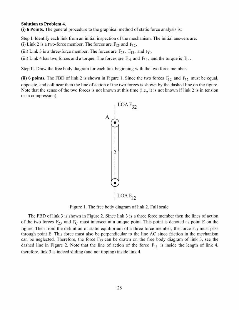
(ii) 6 points.opposite, andNote that theor in compre
The FBDof the two fofigure. Thenthrough poincan be negledashed line therefore, lin
Problem 4. The general
ify each linka two-force s a three-forc
has two force
w the free bo
. The FBD od collinear the sense of thession).
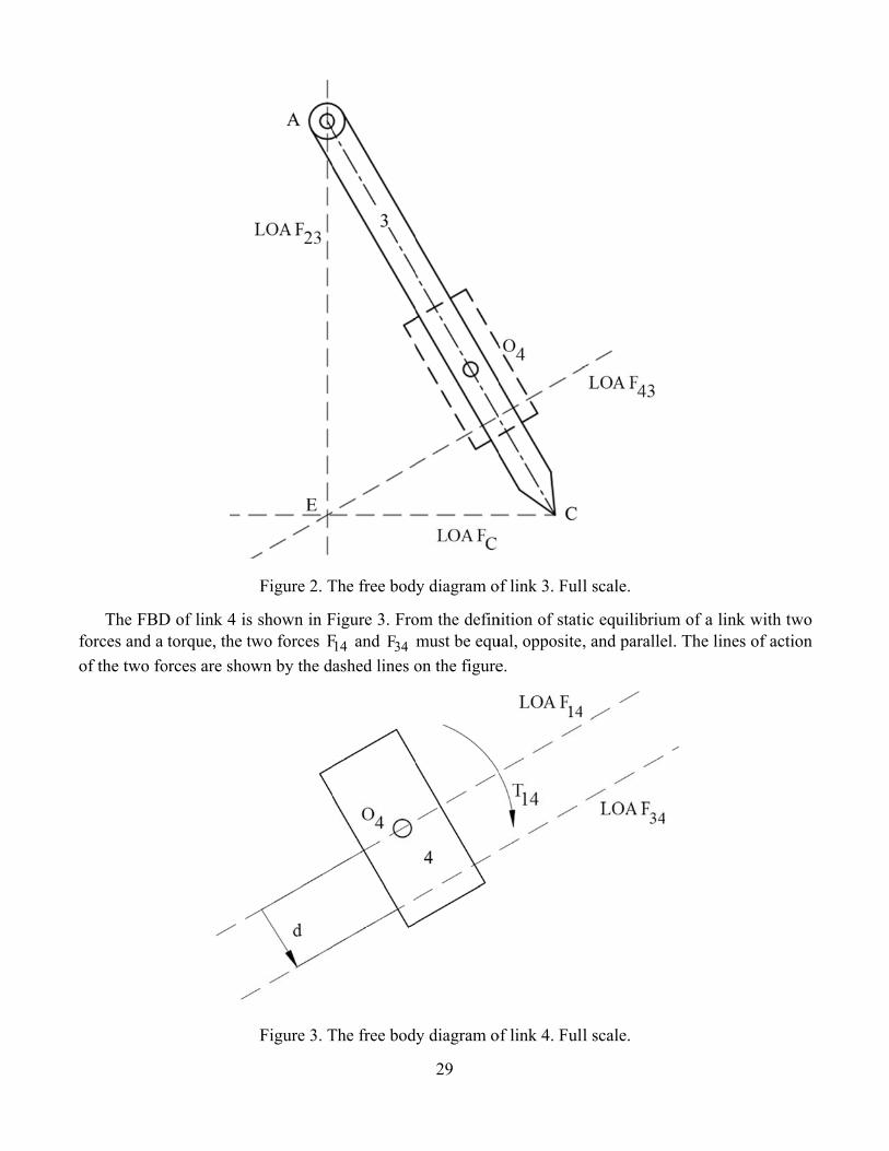
D of link 3 isorces 23F an
from the dent E. This foected. Therein Figure 2
nk 3 is indeed
l procedure t
k from an inimember. Thce member. es and a torq
ody diagram
of link 2 is shen the line e two forces
Figure 1. T
s shown in Fnd CF must efinition of orce must alefore, the fo. Note that d sliding (an
to the graphi
itial inspectiohe forces are The forces a
que. The forc
for each link
shown in Figof action of s is not know
The free bod
Figure 2. Sincintersect at
static equilibso be perpenrce F43 can the line of
nd not tippin
28
ical method o
on of the me12F and 32F
are ,23F 43Fces are 14F a
k beginning
gure 1. Sincethe two forc
wn at this tim
dy diagram o
ce link 3 is aa unique po
brium of a tndicular to tbe drawn oaction of th
ng) inside lin
of static forc
echanism. Th.2
, and .CF and ,34F and
with the two
e the two forces is shownme (i.e., it is
of link 2. Ful
a three forceoint. This pothree force mthe line AC on the free bhe force 43Fnk 4.
ce analysis i
he initial ans
d the torque
o force mem
rces 12F andn by the dash not known
l scale.
e member thoint is denotmember, thesince frictio
body diagra3 is inside t
s:
swers are:
is 14T .
mber.
d 32F must bhed line on thif link 2 is in
hen the lines ted as point e force F43 mon in the meam of link 3the length o
be equal, he figure. n tension
of action E on the
must pass echanism 3, see the of link 4,
fo
The FBDforces and a of the two fo
D of link 4 istorque, the t
orces are sho
Figure 2. T
s shown in Ftwo forces F
own by the d
Figure 3. T
The free bod
Figure 3. Fro14F and 34Fashed lines o
The free bod
29
dy diagram o
om the definmust be equon the figure
dy diagram o
of link 3. Ful
nition of statiual, oppositee.
of link 4. Ful
l scale.
ic equilibriu, and paralle
l scale.
um of a link el. The lines
with two of action

(
o
T
Si
T
fi
C
(iii) 9 points
or as
The distance
Substituting nternal react
The internal
force must bn Figure 4 a
Consider the
s. The sum o
e from the cr
the known tion force be
reaction forc
e as shown iand the magn
Figure
e free body d
f the momen
ankshaft O4
torque 14T =etween links
ce 34F must
in Figure 4. nitude of this
e 4. The inte
diagram of lin
nts about the
∑
d+
to the line o
d
5 Nm= and 4 and 3 is
1434
TFd
=
t oppose the
Then the ints force is
34F =
ernal reaction
nk 3, see Fig
30
e crankshaft
40OM∑ =
34 14 0d F T− =
of action of t
15.6 mmd =
d Equation (
5 Nm0.0156 m
=
action of the
ternal reactio
14 320.5F= =
n forces 34F
gure 2, repea
O4 can be w
0
the force 34F
(3) into Equ
320.5 Nm=
e external to
on force 14F
5 N
and 14F ac
ated here as
written as
4 , see Figure
uation (2b)
orque, that is
4 must act in
ting on link
Figure 5.
e 3, is measu
and rearran
s, the directio
n the directio
4.
(2a)
(2b)
ured as
(3)
ging, the
(4)
on of this
on shown
(5)
(
o
R
T
S
T
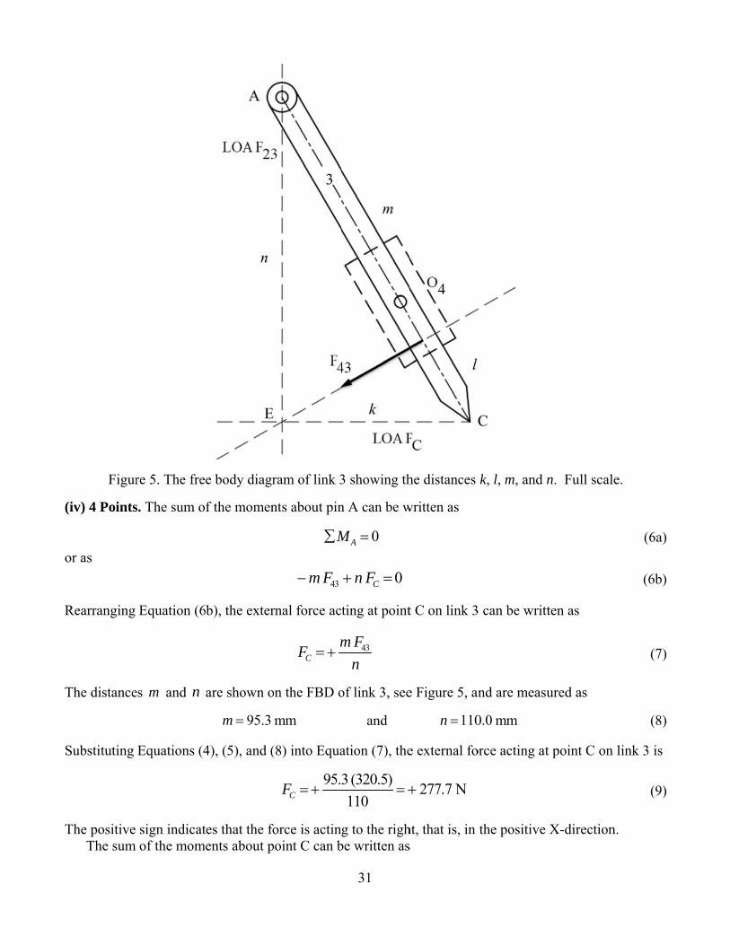
Figur
(iv) 4 Points
or as
Rearranging
The distance
Substituting
The positive The sum
re 5. The fre
s. The sum o
Equation (6
es m and n
Equations (4
sign indicatof the mom
e body diagr
f the momen
6b), the exter
are shown o
95.3m =
4), (5), and (
tes that the foments about p
ram of link 3
nts about pin
M∑
43m F−
rnal force ac
CmF =+
on the FBD o
mm
(8) into Equa
95.CF = +
force is actinpoint C can b
31
3 showing th
n A can be w
0AM =
0Cn F+ =
ting at point
43m Fn
of link 3, see
and
ation (7), the
3 (320.5)110
= +
g to the righbe written as
he distances
written as
t C on link 3
e Figure 5, an
110n =
e external fo
277.7 N+
ht, that is, in s
k, l, m, and
3 can be writ
nd are meas
0.0 mm
orce acting at
the positive
n. Full scale
tten as
ured as
t point C on
X-direction
e.
(6a)
(6b)
(7)
(8)
link 3 is
(9)
n.

o
R
T
S
T
t
or as
Rearranging
The distance
Substituting
The positive The mag
Fig
The FBDtwo forces ar
Equation (1
es k and l ar
Equations (5
sign indicatnitudes and
gure 6. The f
D of link 2 shre equal, opp
0b), the exte
re shown on
63.5 mk =
5), and (12)
tes that the rethe direction
free body dia
howing the iposite, and c
M∑
43l F+ −
ernal force a
23F =
n the FBD of
mm
into Equatio
2331F =+
eaction forcens of the two
agram of link
internal reacollinear then
32
0CM =
23 0k F− =
acting at poin
43l Fk
=+
f link 3, see F
and
on (11), the e
1.8 (320.5)63.5
=
e is acting upo forces CF
k 3 showing
ction forces n link 2 must
nt A on link
Figure 5, and
31.8l =
external forc
160.5 N= +
pward (that and 23F are
g the forces F
12F and 32Ft be in comp
3 can be wr
d are measur
8 mm
ce acting at p
is, in the poe shown on F
CF and 23F .
2 is shown inpression.
ritten as
red as
point A on li
sitive Y direFigure 6.
. Full scale.
n Figure 7. S
(10a)
(10b)
(11)
(12)
ink 3 is
(13)
ection).
Since the
C
f
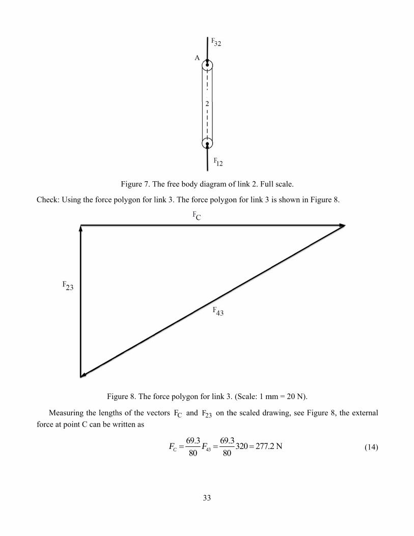
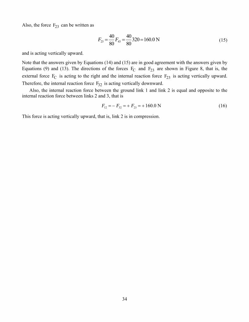
Check: Using
Measurinforce at poin
g the force p
Fig
ng the lengthnt C can be w
Figure 7. T
polygon for l
gure 8. The f
hs of the vecwritten as
The free bod
link 3. The f
force polygo
ctors CF an
6980CF =
33
dy diagram o
force polygo
on for link 3.
nd 23F on th
439.3 69.30 80
F =
of link 2. Ful
on for link 3
(Scale: 1 m
he scaled dra
3320 277.2=
l scale.
is shown in
mm = 20 N).
awing, see F
2 N
Figure 8.
Figure 8, the
e external
(14)
34
Also, the force 23F can be written as
23 4340 40320 160.0 N80 80
F F= = = (15) and is acting vertically upward. Note that the answers given by Equations (14) and (15) are in good agreement with the answers given by Equations (9) and (13). The directions of the forces CF and 23F are shown in Figure 8, that is, the external force CF is acting to the right and the internal reaction force 23F is acting vertically upward. Therefore, the internal reaction force 32F is acting vertically downward.
Also, the internal reaction force between the ground link 1 and link 2 is equal and opposite to the internal reaction force between links 2 and 3, that is
12 32 23 160.0 NF F F= − = + = + (16) This force is acting vertically upward, that is, link 2 is in compression.