RADIOMETRY Photometry General Radiometry Making light work of light MeasureMent 1 Application...
8
The Guide To RADIOMETRY MAKING LIGHT WORK OF LIGHT MEASUREMENT
-
Upload
duongthien -
Category
Documents
-
view
226 -
download
1
Transcript of RADIOMETRY Photometry General Radiometry Making light work of light MeasureMent 1 Application...
Th e G u i d e To
RADIOMETRY
Making light work of light MeasureMent
Making light work of light MeasureMent
9925 Carroll Canyon Rd., San Diego, CA 92131 • (858) 279-8034 • www.gamma-sci.com/udtinstruments
�
Appl�cat�on Informat�on
Introduct�on . . . . . . . . . . . . . . . . . . . . . . . . . . . . . . . . . . . . . . . . . . . . . . . . . . . . . . . . . . . . . . . . . . . . 1Important Terms . . . . . . . . . . . . . . . . . . . . . . . . . . . . . . . . . . . . . . . . . . . . . . . . . . . . . . . . . . . . . . . . 2Cal�brat�on of Sensors . . . . . . . . . . . . . . . . . . . . . . . . . . . . . . . . . . . . . . . . . . . . . . . . . . . . . . . . . . . 4How to Spec�fy a Rad�ometer System . . . . . . . . . . . . . . . . . . . . . . . . . . . . . . . . . . . . . . . . . . . . 5
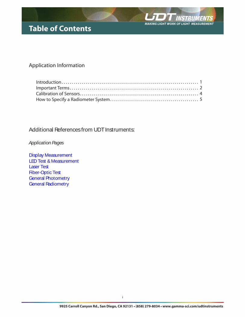
Table of Contents
Additional References from UDT Instruments:
Application Pages
Display MeasurementLED Test & Measurement Laser TestFiber-Optic TestGeneral PhotometryGeneral Radiometry
Making light work of light MeasureMent
1
Application information
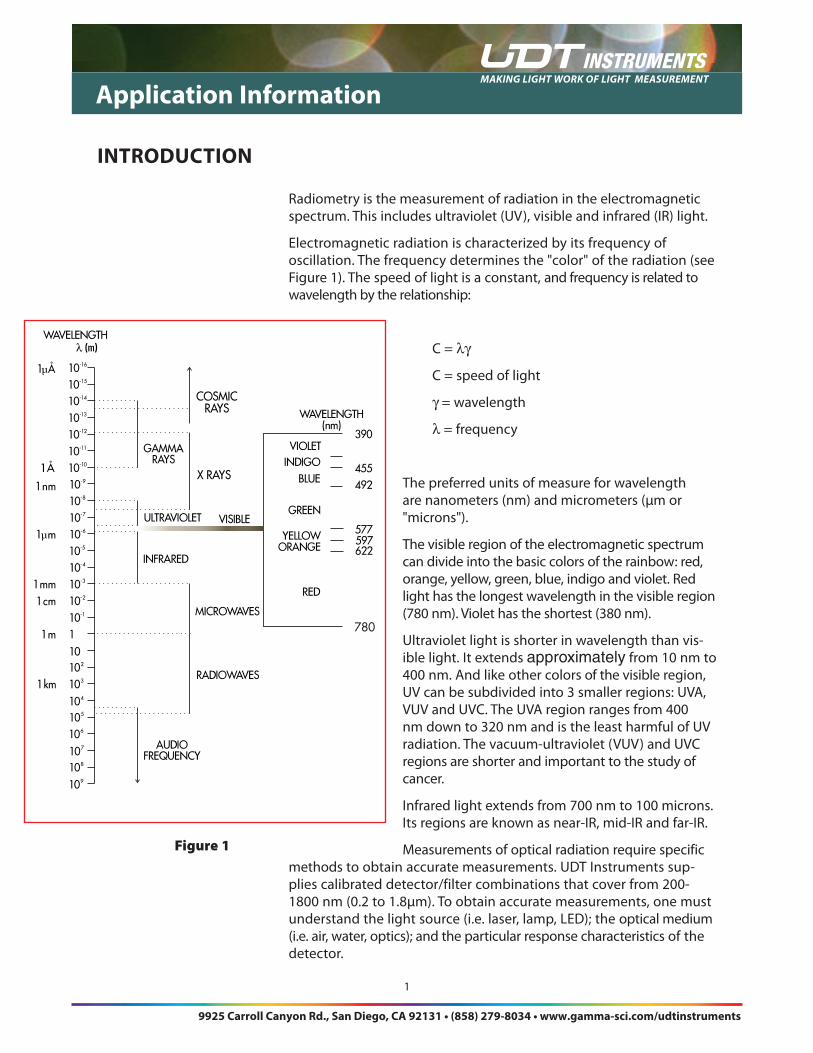
Rad�ometry �s the measurement of rad�at�on �n the electromagnet�c spectrum . Th�s �ncludes ultrav�olet (UV), v�s�ble and �nfrared (IR) l�ght .
Electromagnet�c rad�at�on �s character�zed by �ts frequency of osc�llat�on . The frequency determ�nes the "color" of the rad�at�on (see F�gure 1) . The speed of l�ght �s a constant, and frequency �s related to wavelength by the relat�onsh�p:
C = λγ
C = speed of l�ght
γ = wavelength
λ = frequency
The preferred un�ts of measure for wavelength are nanometers (nm) and m�crometers (µm or "m�crons") .
The v�s�ble reg�on of the electromagnet�c spectrum can d�v�de �nto the bas�c colors of the ra�nbow: red, orange, yellow, green, blue, �nd�go and v�olet . Red l�ght has the longest wavelength �n the v�s�ble reg�on (780 nm) . V�olet has the shortest (380 nm) .
Ultrav�olet l�ght �s shorter �n wavelength than v�s-�ble l�ght . It extends approximately from 10 nm to 400 nm . And l�ke other colors of the v�s�ble reg�on, UV can be subd�v�ded �nto 3 smaller reg�ons: UVA, VUV and UVC . The UVA reg�on ranges from 400 nm down to 320 nm and �s the least harmful of UV rad�at�on . The vacuum-ultrav�olet (VUV) and UVC reg�ons are shorter and �mportant to the study of cancer .
Infrared l�ght extends from 700 nm to 100 m�crons . Its reg�ons are known as near-IR, m�d-IR and far-IR .
Measurements of opt�cal rad�at�on requ�re spec�f�c methods to obta�n accurate measurements . UDT Instruments sup-pl�es cal�brated detector/f�lter comb�nat�ons that cover from 200-1800 nm (0 .2 to 1 .8µm) . To obta�n accurate measurements, one must understand the l�ght source (� .e . laser, lamp, LED); the opt�cal med�um (� .e . a�r, water, opt�cs); and the part�cular response character�st�cs of the detector .
inTroDuCTion
Figure 1
λ
780
9925 Carroll Canyon Rd., San Diego, CA 92131 • (858) 279-8034 • www.gamma-sci.com/udtinstruments
Making light work of light MeasureMent
2
imPorTAnT TermS
Application information
In order to accurately descr�be an opt�cal source, one must use the correct un�ts and know how these un�ts apply to detector-based rad�ometry . In prac-t�cal l�ght measurement appl�cat�ons, the rece�ver of opt�cal rad�at�on �s a detec-t�on dev�ce that converts opt�cal rad�at�on to electr�cal current accord�ng to a known relat�onsh�p .The chart d�splayed on the
l left �s a short breakdown of rad�ometr�c terms and the�r correspond�ng un�ts of measure .
radiant energyRad�ant energy refers to the amount of power reach�ng a g�ven po�nt accu-mulated over t�me . Th�s �s referred to as joules (watt-second).
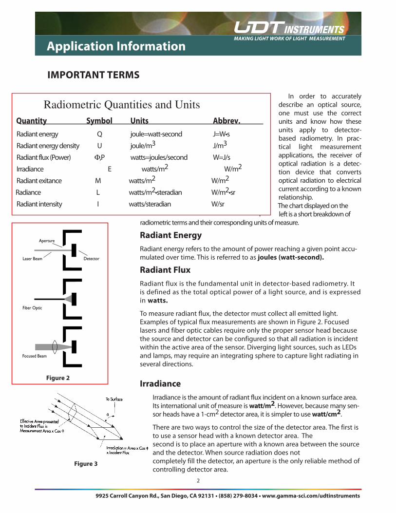
radiant fluxRad�ant flux �s the fundamental un�t �n detector-based rad�ometry . It �s def�ned as the total opt�cal power of a l�ght source, and �s expressed �n watts.
To measure rad�ant flux, the detector must collect all em�tted l�ght . Examples of typ�cal flux measurements are shown �n F�gure 2 . Focused lasers and f�ber opt�c cables requ�re only the proper sensor head because the source and detector can be conf�gured so that all rad�at�on �s �nc�dent w�th�n the act�ve area of the sensor . D�verg�ng l�ght sources, such as LEDs and lamps, may requ�re an �ntegrat�ng sphere to capture l�ght rad�at�ng �n several d�rect�ons .
irradianceIrrad�ance �s the amount of rad�ant flux �nc�dent on a known surface area . Its �nternat�onal un�t of measure �s watt/m2 . However, because many sen-sor heads have a 1-cm2 detector area, �t �s s�mpler to use watt/cm2 .
There are two ways to control the s�ze of the detector area . The f�rst �s to use a sensor head w�th a known detector area . The second �s to place an aperture w�th a known area between the source and the detector . When source rad�at�on does not completely f�ll the detector, an aperture �s the only rel�able method of controll�ng detector area .
Quantity Symbol units Abbrev.
Rad�ant energy Q joule=watt-second J=W•s
Rad�ant energy dens�ty U joule/m3 J/m3
Rad�ant flux (Power) Φ,P watts=joules/second W=J/s
Irrad�ance E watts/m2 W/m2
Rad�ant ex�tance M watts/m2 W/m2
Rad�ance L watts/m2•sterad�an W/m2•sr
Rad�ant �ntens�ty I watts/sterad�an W/sr
Radiometric Quantities and Units
figure 3
Focused Beam
Fiber Optic
Laser Beam
Aperture
Detector
figure 2
9925 Carroll Canyon Rd., San Diego, CA 92131 • (858) 279-8034 • www.gamma-sci.com/udtinstruments
Making light work of light MeasureMent
3
imPorTAnT TermS
Application information
radiant exitanceRad�ant Ex�tance, a property of the l�ght source, �s the total rad�ant flux from the source d�v�ded by the surface area of the source . Its un�t of measure �s watt/m2, s�mpl�f�ed as watt/cm2 . Th�s type ofmeasurement only appl�es to extended l�ght sources and �s useful for mak�ng eff�c�ency measurements of d�fferent l�ght source mater�als .
To make rad�ant ex�stence measurements, one must know the surface area of the source and then measure the total rad�ant flux leav�ng the source .
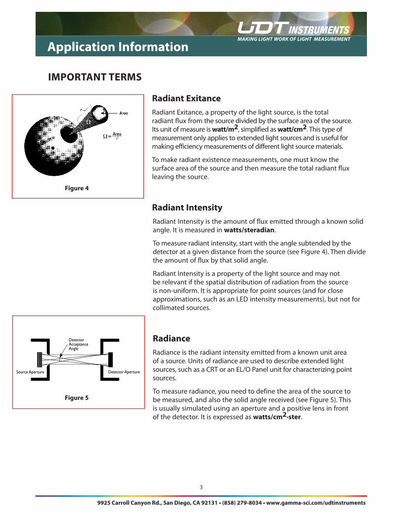
radiant intensity Rad�ant Intens�ty �s the amount of flux em�tted through a known sol�d angle . It �s measured �n watts/steradian .
To measure rad�ant �ntens�ty, start w�th the angle subtended by the detector at a g�ven d�stance from the source (see F�gure 4) . Then d�v�de the amount of flux by that sol�d angle .
Rad�ant Intens�ty �s a property of the l�ght source and may not be relevant �f the spat�al d�str�but�on of rad�at�on from the source �s non-un�form . It �s appropr�ate for po�nt sources (and for close approx�mat�ons, such as an LED �ntens�ty measurements), but not for
coll�mated sources .
radianceRad�ance �s the rad�ant �ntens�ty em�tted from a known un�t area of a source . Un�ts of rad�ance are used to descr�be extended l�ght sources, such as a CRT or an EL/O Panel un�t for character�z�ng po�nt sources .
To measure rad�ance, you need to def�ne the area of the source to be measured, and also the sol�d angle rece�ved (see F�gure 5) . Th�s �s usually s�mulated us�ng an aperture and a pos�t�ve lens �n front of the detector . It �s expressed as watts/cm2·ster .
figure 4
DetectorAcceptanceAngle
Source Aperture Detector Aperture
figure 5
9925 Carroll Canyon Rd., San Diego, CA 92131 • (858) 279-8034 • www.gamma-sci.com/udtinstruments
Making light work of light MeasureMent
4
Application information
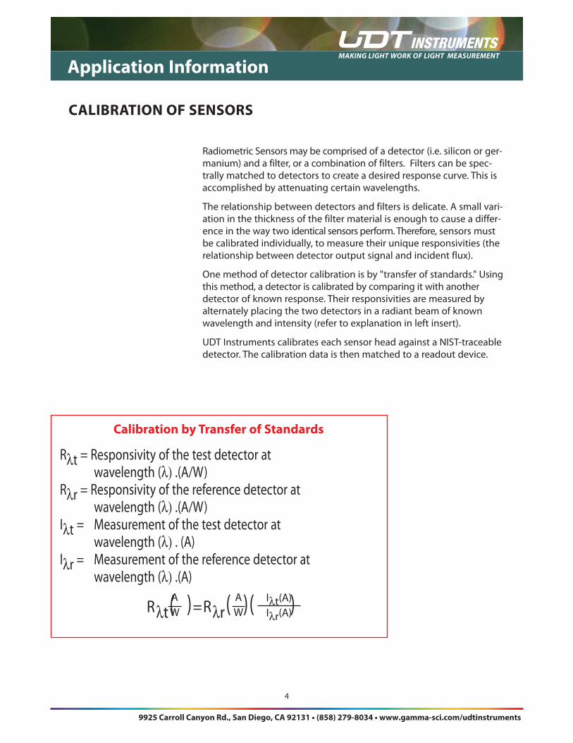
Rad�ometr�c Sensors may be compr�sed of a detector (� .e . s�l�con or ger-man�um) and a f�lter, or a comb�nat�on of f�lters . F�lters can be spec-trally matched to detectors to create a des�red response curve . Th�s �s accompl�shed by attenuat�ng certa�n wavelengths .
The relat�onsh�p between detectors and f�lters �s del�cate . A small var�-at�on �n the th�ckness of the f�lter mater�al �s enough to cause a d�ffer-ence �n the way two �dent�cal sensors perform . Therefore, sensors must be cal�brated �nd�v�dually, to measure the�r un�que respons�v�t�es (the relat�onsh�p between detector output s�gnal and �nc�dent flux) .
One method of detector cal�brat�on �s by "transfer of standards ." Us�ng th�s method, a detector �s cal�brated by compar�ng �t w�th another detector of known response . The�r respons�v�t�es are measured by alternately plac�ng the two detectors �n a rad�ant beam of known wavelength and �ntens�ty (refer to explanat�on �n left �nsert) .
UDT Instruments cal�brates each sensor head aga�nst a NIST-traceable detector . The cal�brat�on data �s then matched to a readout dev�ce .
Calibration by Transfer of Standards
Rλt = Respons�v�ty of the test detector atwavelength (λ) .(A/W)
Rλr = Respons�v�ty of the reference detector atwavelength (λ) .(A/W)
Iλt = Measurement of the test detector atwavelength (λ) . (A)
Iλr = Measurement of the reference detector atwavelength (λ) .(A)
CAlibrATion of SenSorS
Rλt(A)=Rλr(A)(I lt(A)AW
AW
Iλt(A)Iλr(A)
9925 Carroll Canyon Rd., San Diego, CA 92131 • (858) 279-8034 • www.gamma-sci.com/udtinstruments9925 Carroll Canyon Rd., San Diego, CA 92131 • (858) 279-8034 • www.gamma-sci.com/udtinstruments
9925 Carroll Canyon Rd., San Diego, CA 92131 • (858) 279-8034 • www.gamma-sci.com/udtinstruments
Making light work of light MeasureMent
5
Select�ng a properly cal�brated Rad�ometr�c head and the r�ght readout dev�ce are �mportant �n obta�n�ng accurate results .
The sensor head converts electromagnet�c rad�at�on �nto an electr�cal s�gnal . The readout dev�ce then rece�ves th�s s�gnal and �nterprets �t . A properly cal�brated measurement system w�ll measure the l�ght source and d�splay the measurement �n the appropr�ate opt�cal un�ts .
The readout un�t should be selected accord�ng to �ts features, and the detector head should be selected accord�ng to �ts power measurement range, wavelength cal�brat�on and s�ze . The two matched together
w�ll accurately measure the source �n the correct opt�cal un�ts .
Consider The SourceAs descr�bed prev�ously �n the “�mportant terms” sect�on, opt�cal sources are character-�zed by certain units
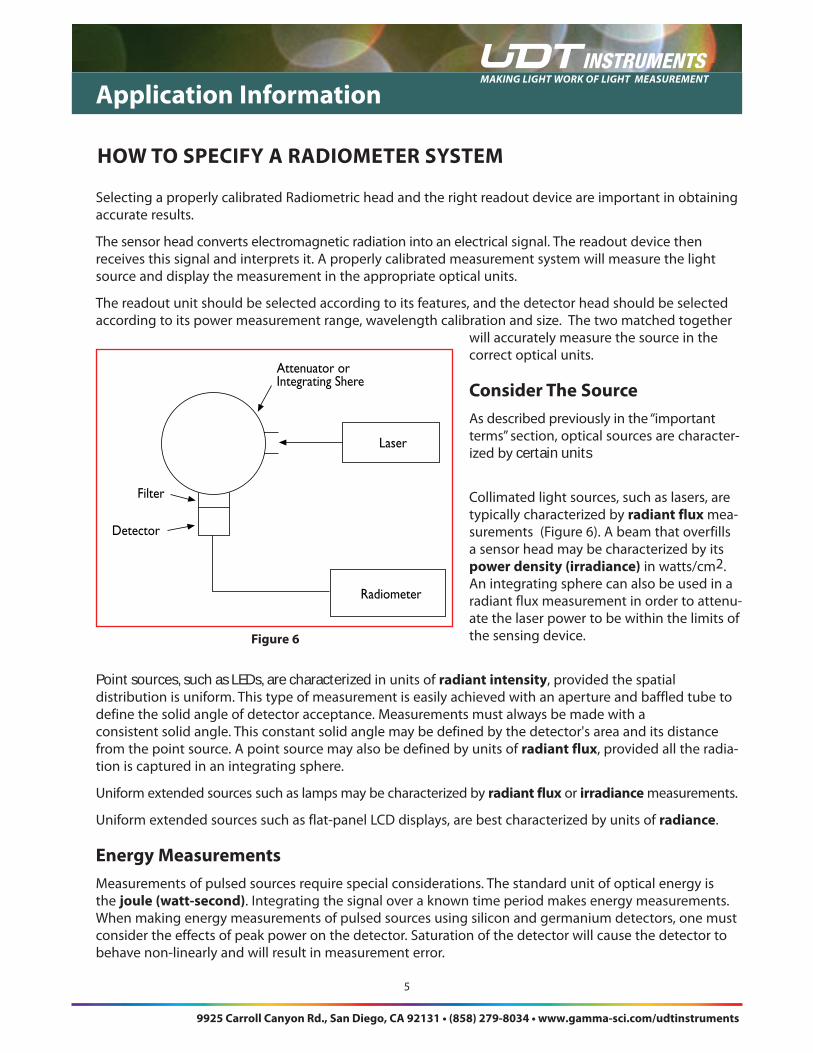
Coll�mated l�ght sources, such as lasers, are typ�cally character�zed by radiant flux mea-surements (F�gure 6) . A beam that overf�lls a sensor head may be character�zed by �ts power density (irradiance) �n watts/cm2 . An �ntegrat�ng sphere can also be used �n a rad�ant flux measurement �n order to attenu-ate the laser power to be w�th�n the l�m�ts of the sens�ng dev�ce .
Point sources, such as LEDs, are characterized �n un�ts of radiant intensity, prov�ded the spat�al d�str�but�on �s un�form . Th�s type of measurement �s eas�ly ach�eved w�th an aperture and baffled tube to def�ne the sol�d angle of detector acceptance . Measurements must always be made w�th a cons�stent sol�d angle . Th�s constant sol�d angle may be def�ned by the detector's area and �ts d�stance from the po�nt source . A po�nt source may also be def�ned by un�ts of radiant flux, prov�ded all the rad�a-t�on �s captured �n an �ntegrat�ng sphere .
Un�form extended sources such as lamps may be character�zed by radiant flux or irradiance measurements .
Un�form extended sources such as flat-panel LCD d�splays, are best character�zed by un�ts of radiance .
energy measurementsMeasurements of pulsed sources requ�re spec�al cons�derat�ons . The standard un�t of opt�cal energy �s the joule (watt-second) . Integrat�ng the s�gnal over a known t�me per�od makes energy measurements . When mak�ng energy measurements of pulsed sources us�ng s�l�con and german�um detectors, one must cons�der the effects of peak power on the detector . Saturat�on of the detector w�ll cause the detector to behave non-l�nearly and w�ll result �n measurement error .
Application information
Attenuator orIntegrating Shere
Laser
Radiometer
Filter
Detector
figure 6
HoW To SPeCify A rADiomeTer SySTem
9925 Carroll Canyon Rd., San Diego, CA 92131 • (858) 279-8034 • www.gamma-sci.com/udtinstruments
Making light work of light MeasureMent
6
Application information
Wavelength and optical filters Opt�cal f�lters can be des�gned to allow certa�n wavelengths to pass through, wh�le screen�ng out others . A f�lter can be selected to mod�fy a detector's response �n order to l�m�t the bandpass to match some des�red response curve or to attenuate the �nput s�gnal by a known amount . Many f�lter and detector
c comb�nat�ons must be cal�brated to ensure measurement accuracy .
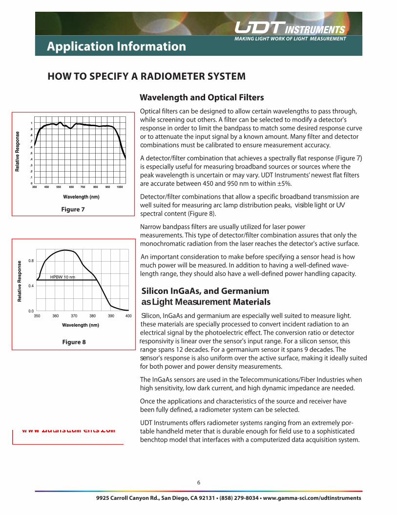
A detector/f�lter comb�nat�on that ach�eves a spectrally flat response (F�gure 7) �s espec�ally useful for measur�ng broadband sources or sources where the peak wavelength �s uncerta�n or may vary . UDT Instruments’ newest flat f�lters are accurate between 450 and 950 nm to w�th�n ±5% .
Detector/f�lter comb�nat�ons that allow a spec�f�c broadband transm�ss�on are well su�ted for measur�ng arc lamp d�str�but�on peaks, visible light or UV spectral content (F�gure 8) .
Narrow bandpass f�lters are usually ut�l�zed for laser power measurements . Th�s type of detector/f�lter comb�nat�on assures that only the monochromat�c rad�at�on from the laser reaches the detector's act�ve surface .
An �mportant cons�derat�on to make before spec�fy�ng a sensor head �s how much power w�ll be measured . In add�t�on to hav�ng a well-def�ned wave- length range, they should also have a well-def�ned power handl�ng capac�ty .
Silicon ingaAs, and germanium as Light Measurement materialsS S�l�con, InGaAs and german�um are espec�ally well su�ted to measure l�ght . T these mater�als are spec�ally processed to convert �nc�dent rad�at�on to an electr�cal s�gnal by the photoelectr�c effect . The convers�on rat�o or detector r respons�v�ty �s l�near over the sensor's �nput range . For a s�l�con sensor, th�s range spans 12 decades . For a german�um sensor �t spans 9 decades . The sensor's response �s also un�form over the act�ve surface, mak�ng �t �deally su�ted for both power and power dens�ty measurements .
The InGaAs sensors are used �n the Telecommun�cat�ons/F�ber Industr�es when h�gh sens�t�v�ty, low dark current, and h�gh dynam�c �mpedance are needed .
Once the appl�cat�ons and character�st�cs of the source and rece�ver have been fully def�ned, a rad�ometer system can be selected .
UDT Instruments offers rad�ometer systems rang�ng from an extremely por- table handheld meter that �s durable enough for f�eld use to a soph�st�cated benchtop model that �nterfaces w�th a computer�zed data acqu�s�t�on system .
Rel
ativ
e R
espo
nse
Wavelength (nm)
1
.9
.8
.7
.6
.5
.4
.3
.2
.1
0350 450 550 650 750 850 950 1050
figure 7
350360370380390400
0.8
0.4
0.0
Rel
ativ
e R
esp
on
se
Wavelength (nm)
HPBW10nm
figure 8
HoW To SPeCify A rADiomeTer SySTem
9925 Carroll Canyon Rd., San Diego, CA 92131 • (858) 279-8034 • www.gamma-sci.com/udtinstruments
jleland
Text Box
SEE ALSO: The Guide to Photometer & Radiometer System Configuration, available as a free PDF download at: www.udtinstruments.com
jleland
Text Box