Liberalisation and regulation in the telecommunication sector: Theory and empirical evidence
29/06/2011 - 1 ATLCE - D5 - © 2010 DDC
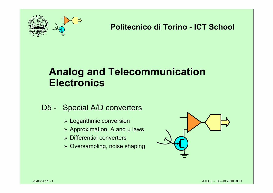
Politecnico di Torino - ICT School
Analog and Telecommunication Electronics
D5 - Special A/D converters» Logarithmic conversion» Approximation, A and μ laws» Differential converters» Oversampling, noise shaping
29/06/2011 - 2 ATLCE - D5 - © 2010 DDC
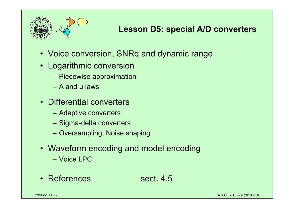
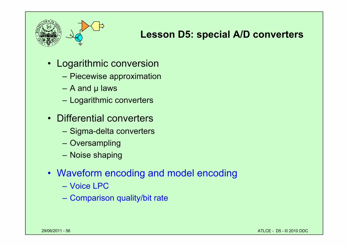
Lesson D5: special A/D converters
• Voice conversion, SNRq and dynamic range• Logarithmic conversion
– Piecewise approximation– A and μ laws
• Differential converters– Adaptive converters– Sigma-delta converters– Oversampling, Noise shaping
• Waveform encoding and model encoding– Voice LPC
• References sect. 4.5
29/06/2011 - 3 ATLCE - D5 - © 2010 DDC
Radio systems: where are ADC/DAC ?
• Services– V battery, TX power, …..
• Baseband chain– A/D e D/A for voice signals
• Receiver chain:– A/D conversion of I/Q components in the IF channel
• Transmitter chain– D/A conversion of synthesized I/Q components
• Software Defined Radio architectures– Most functions by digital/programmable circuits
A/D or D/A conversion very close to antenna
29/06/2011 - 4 ATLCE - D5 - © 2010 DDC
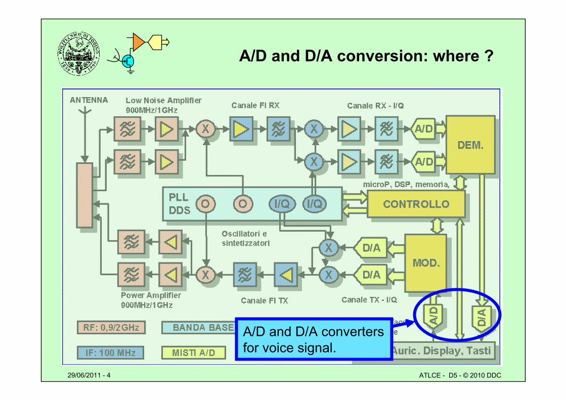
A/D and D/A conversion: where ?
A/D and D/A convertersfor voice signal.

29/06/2011 - 5 ATLCE - D5 - © 2010 DDC
ADC and DAC system goals
• Improve cost/performance figure
– Cost factors» Complexity» Bit rate
– Performance parameters» Bandwidth » Precision
• Signals with known features– Amplitude distribution– Statistic parameters– Model encoding
29/06/2011 - 6 ATLCE - D5 - © 2010 DDC
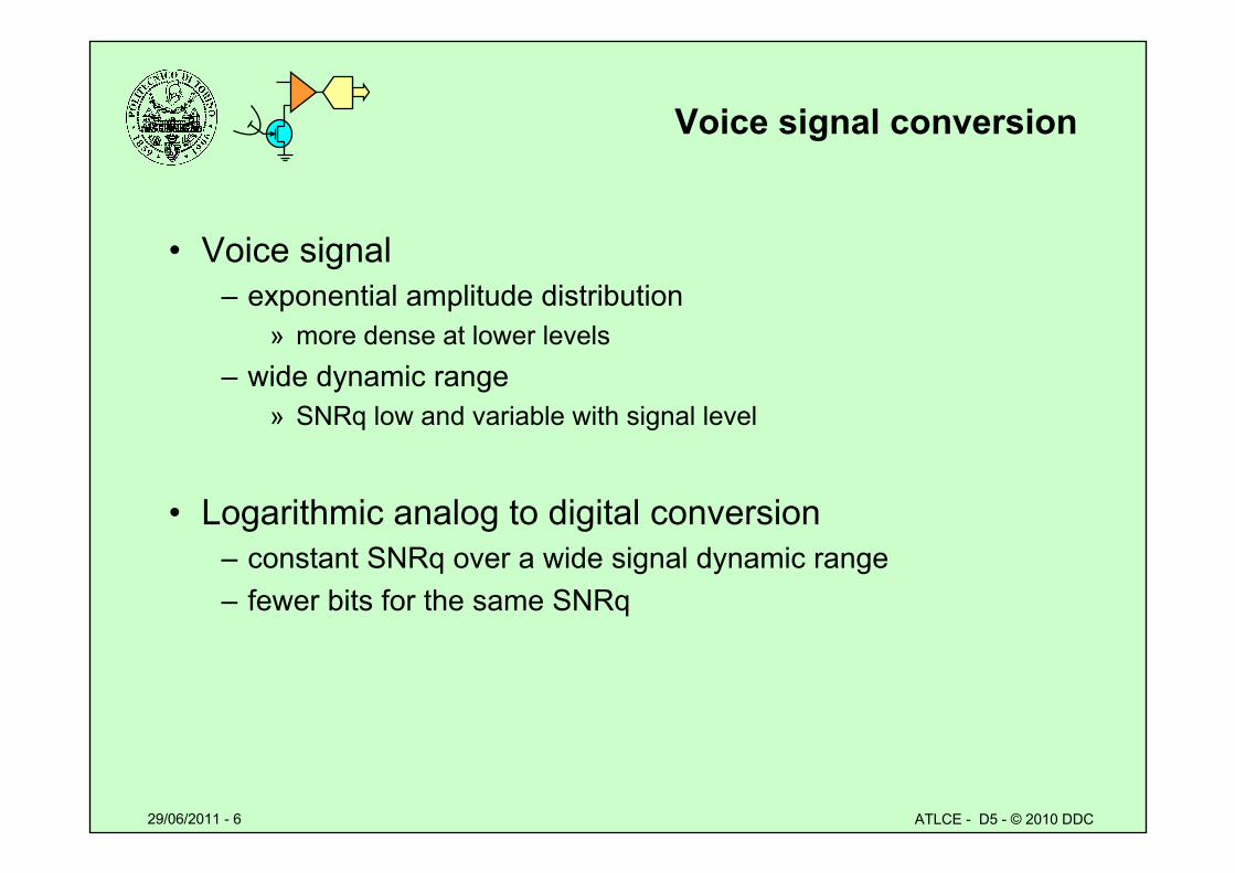
Voice signal conversion
• Voice signal– exponential amplitude distribution
» more dense at lower levels– wide dynamic range
» SNRq low and variable with signal level
• Logarithmic analog to digital conversion – constant SNRq over a wide signal dynamic range– fewer bits for the same SNRq
29/06/2011 - 7 ATLCE - D5 - © 2010 DDC
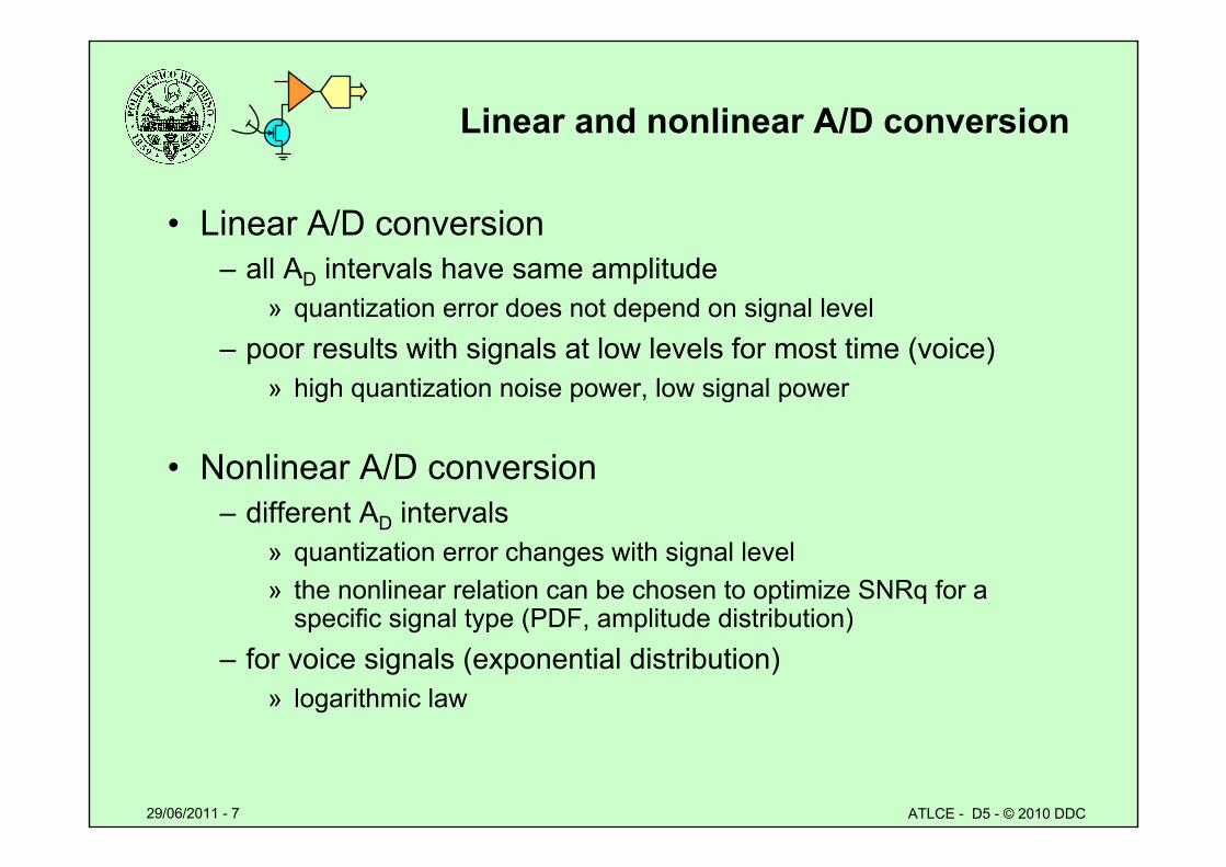
Linear and nonlinear A/D conversion
• Linear A/D conversion– all AD intervals have same amplitude
» quantization error does not depend on signal level– poor results with signals at low levels for most time (voice)
» high quantization noise power, low signal power
• Nonlinear A/D conversion– different AD intervals
» quantization error changes with signal level» the nonlinear relation can be chosen to optimize SNRq for a
specific signal type (PDF, amplitude distribution)– for voice signals (exponential distribution)
» logarithmic law
29/06/2011 - 8 ATLCE - D5 - © 2010 DDC
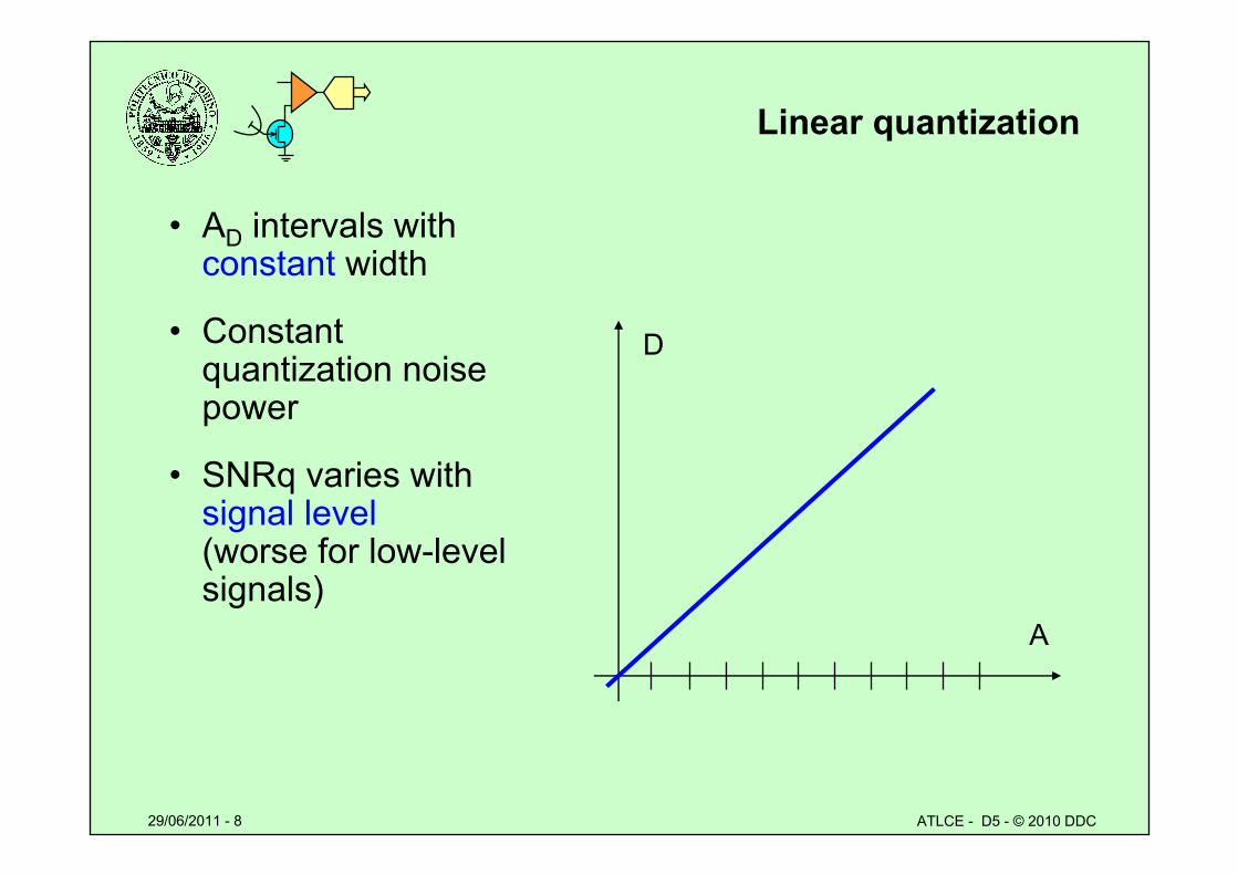
Linear quantization
• AD intervals with constant width
• Constant quantization noise power
• SNRq varies withsignal level(worse for low-levelsignals)
A
D
29/06/2011 - 9 ATLCE - D5 - © 2010 DDC
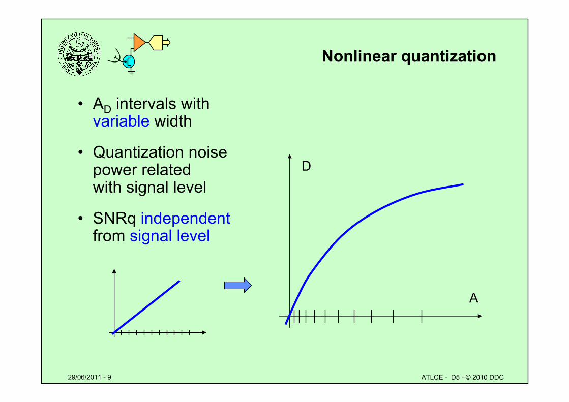
Nonlinear quantization
• AD intervals with variable width
• Quantization noise power related with signal level
• SNRq independentfrom signal level
A
D
29/06/2011 - 10 ATLCE - D5 - © 2010 DDC
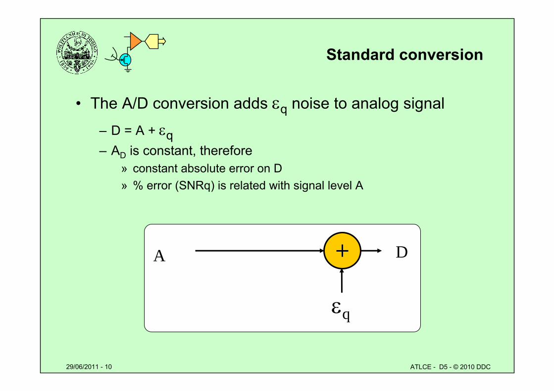
Standard conversion
• The A/D conversion adds q noise to analog signal
– D = A + q– AD is constant, therefore
» constant absolute error on D » % error (SNRq) is related with signal level A
A
q
D
29/06/2011 - 11 ATLCE - D5 - © 2010 DDC
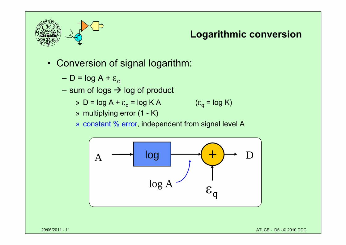
Logarithmic conversion
• Conversion of signal logarithm:– D = log A + q– sum of logs log of product
» D = log A + q = log K A (q = log K)» multiplying error (1 - K)» constant % error, independent from signal level A
A
q
Dlog
log A
29/06/2011 - 12 ATLCE - D5 - © 2010 DDC
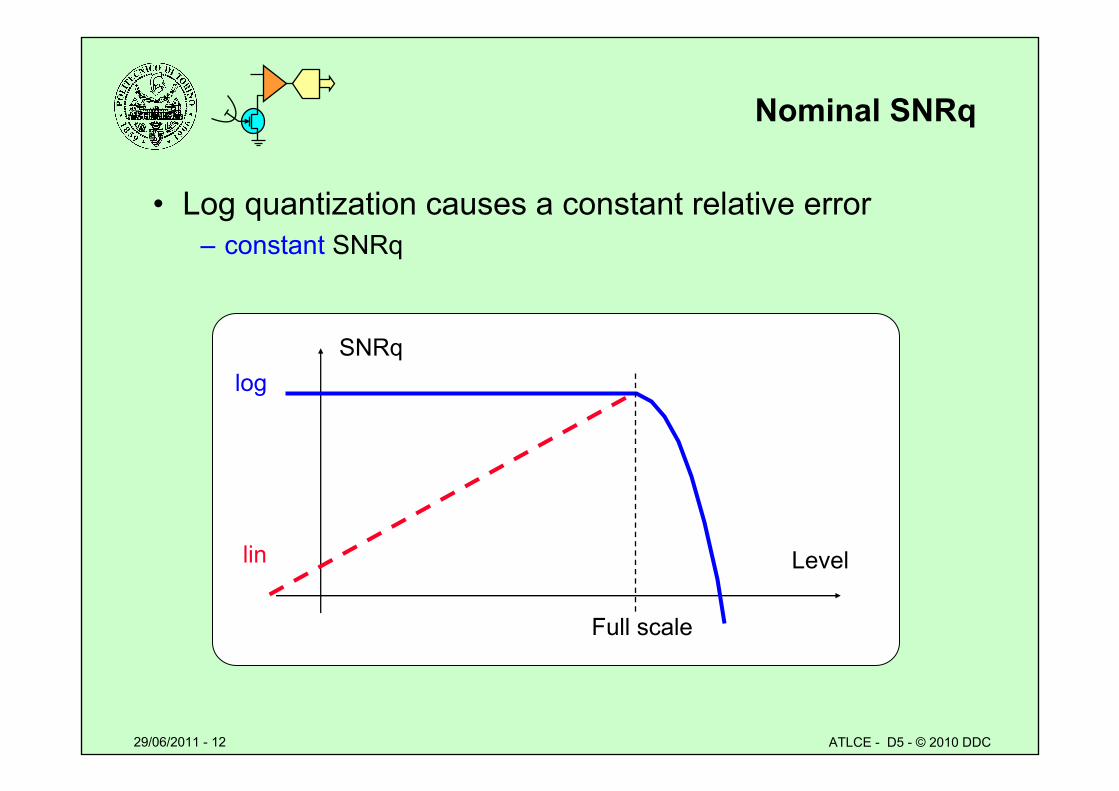
Nominal SNRq
• Log quantization causes a constant relative error– constant SNRq
SNRq
Level
Full scale
log
lin
29/06/2011 - 13 ATLCE - D5 - © 2010 DDC
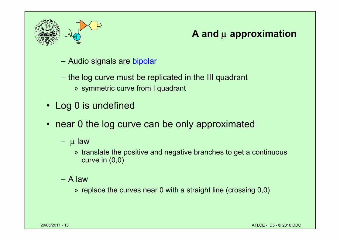
A and approximation
– Audio signals are bipolar
– the log curve must be replicated in the III quadrant » symmetric curve from I quadrant
• Log 0 is undefined
• near 0 the log curve can be only approximated
– law» translate the positive and negative branches to get a continuous
curve in (0,0)
– A law» replace the curves near 0 with a straight line (crossing 0,0)
29/06/2011 - 14 ATLCE - D5 - © 2010 DDC
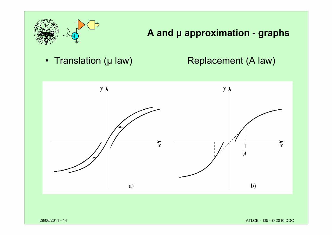
A and μ approximation - graphs
• Translation (μ law) Replacement (A law)
29/06/2011 - 15 ATLCE - D5 - © 2010 DDC
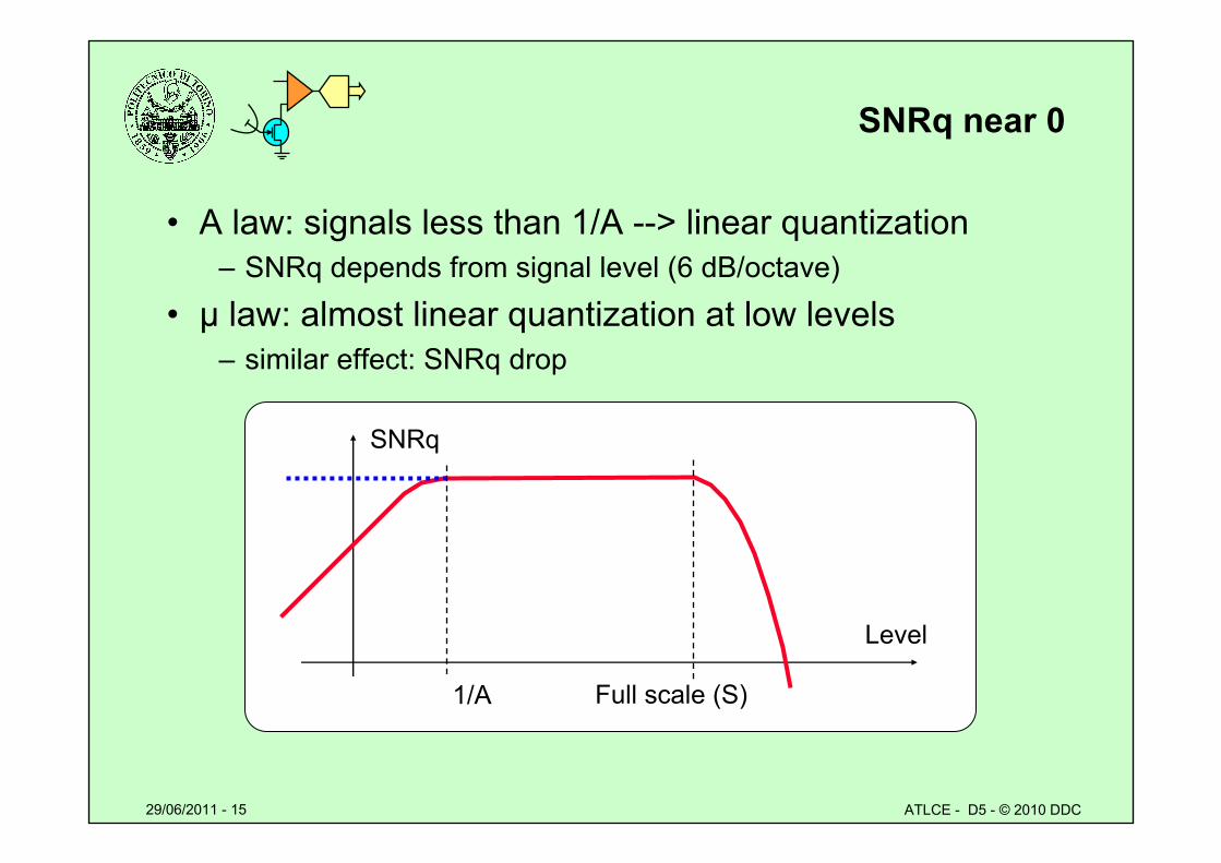
SNRq near 0
• A law: signals less than 1/A --> linear quantization– SNRq depends from signal level (6 dB/octave)
• μ law: almost linear quantization at low levels– similar effect: SNRq drop
SNRq
Level
Full scale (S)1/A
29/06/2011 - 16 ATLCE - D5 - © 2010 DDC
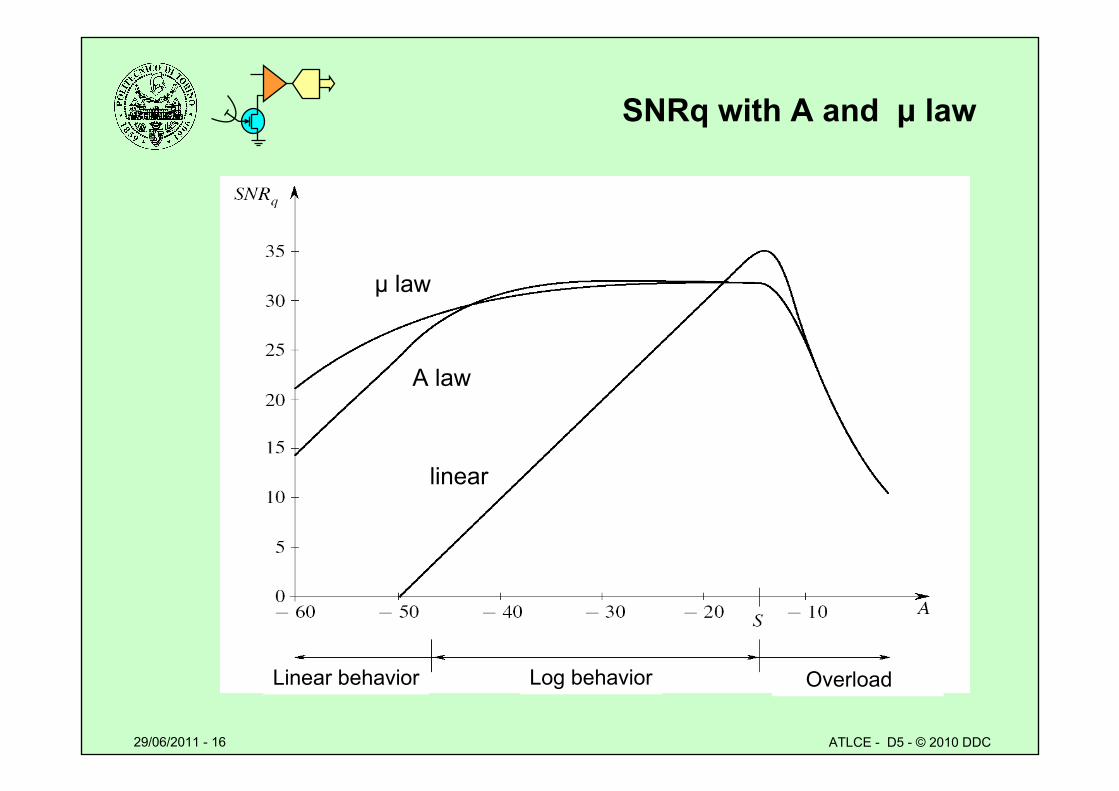
SNRq with A and μ law
μ law
A law
linear
Linear behavior Log behavior Overload
29/06/2011 - 17 ATLCE - D5 - © 2010 DDC
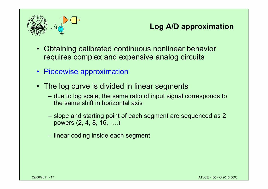
Log A/D approximation
• Obtaining calibrated continuous nonlinear behavior requires complex and expensive analog circuits
• Piecewise approximation
• The log curve is divided in linear segments– due to log scale, the same ratio of input signal corresponds to
the same shift in horizontal axis
– slope and starting point of each segment are sequenced as 2 powers (2, 4, 8, 16, ….)
– linear coding inside each segment
29/06/2011 - 18 ATLCE - D5 - © 2010 DDC
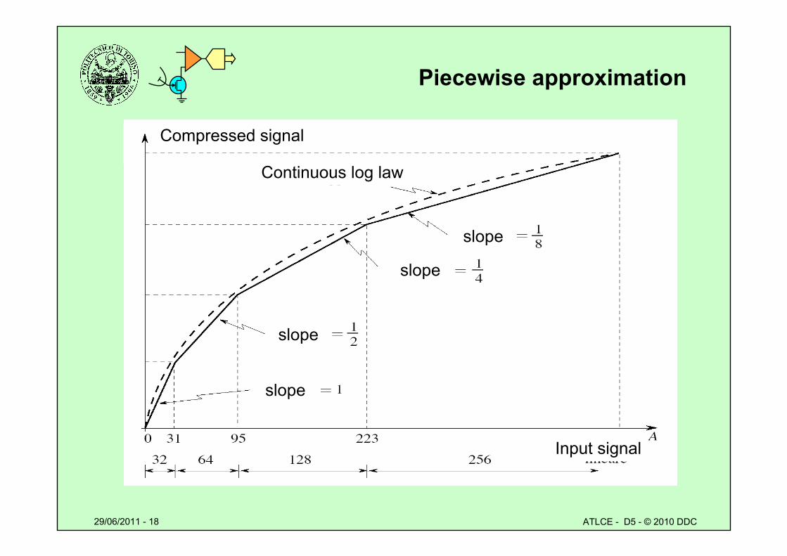
Piecewise approximation
Compressed signal
Continuous log law
slope
slope
slope
slope
Input signal
29/06/2011 - 19 ATLCE - D5 - © 2010 DDC
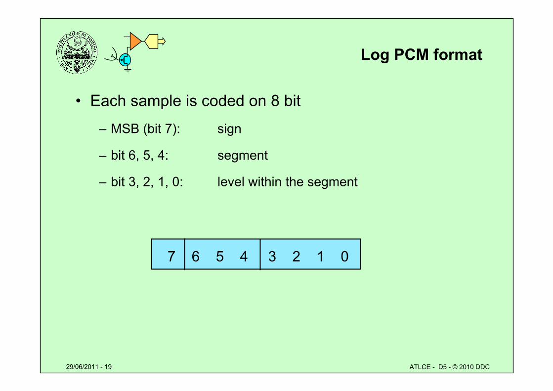
Log PCM format
• Each sample is coded on 8 bit
– MSB (bit 7): sign
– bit 6, 5, 4: segment
– bit 3, 2, 1, 0: level within the segment
7 6 5 4 3 2 1 0
29/06/2011 - 20 ATLCE - D5 - © 2010 DDC
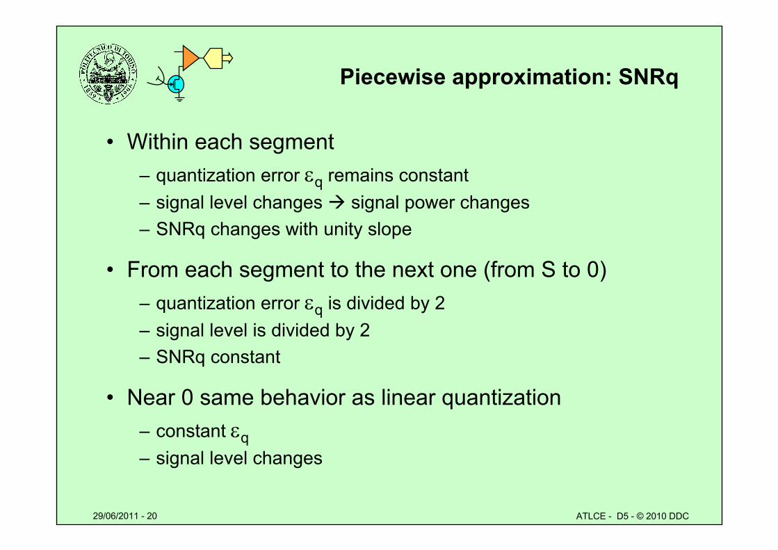
Piecewise approximation: SNRq
• Within each segment – quantization error q remains constant– signal level changes signal power changes – SNRq changes with unity slope
• From each segment to the next one (from S to 0)– quantization error q is divided by 2– signal level is divided by 2– SNRq constant
• Near 0 same behavior as linear quantization– constant q– signal level changes
29/06/2011 - 21 ATLCE - D5 - © 2010 DDC
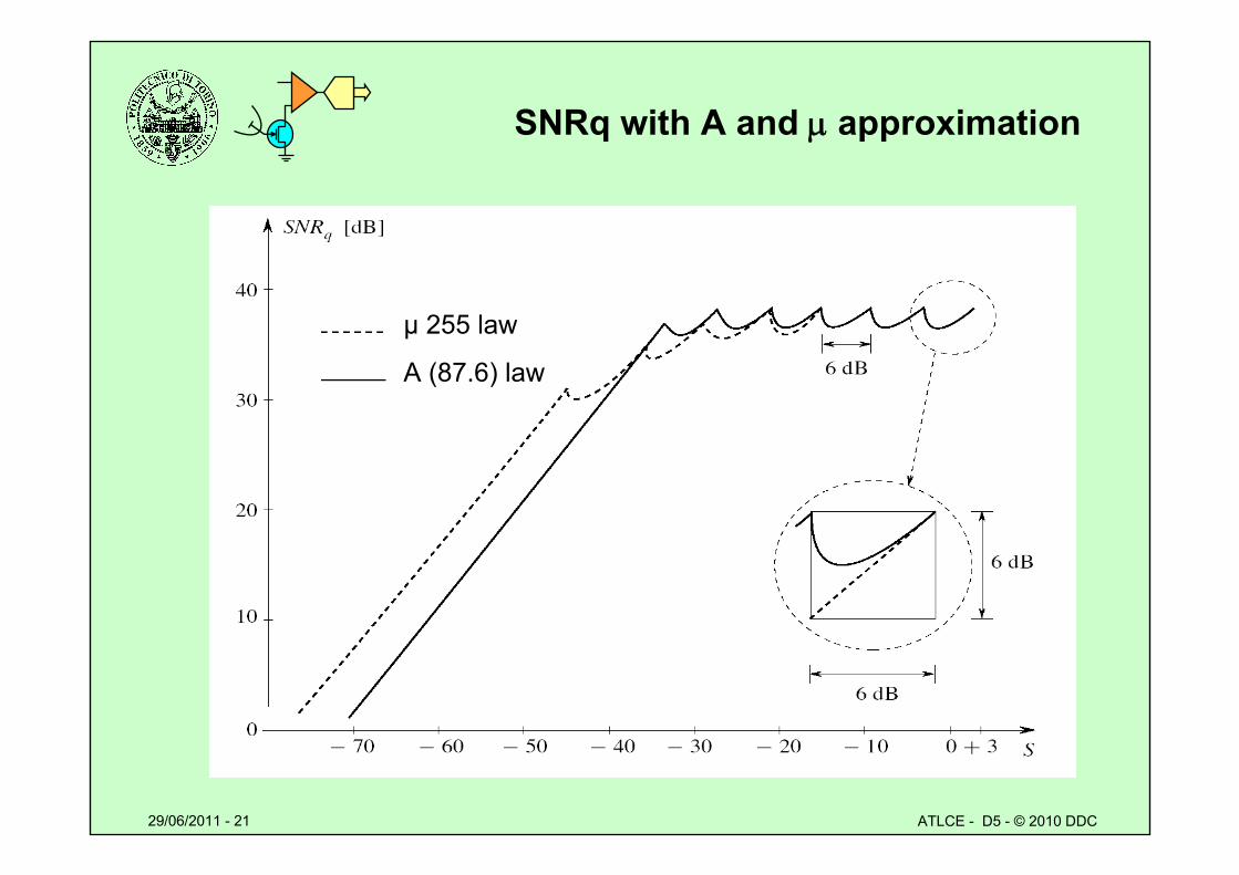
SNRq with A and approximation
μ 255 law
A (87.6) law
29/06/2011 - 22 ATLCE - D5 - © 2010 DDC
Log conversion techniques
• Analog log circuit, followed by A/D– poor precision and stability in the analog circuit– high cost
• High resolution A/D conversion, followed by digital log encoding
– makes available both the linear and log conversion
• Intrinsic log A/D converter– nonlinear law A/D or D/A conversion– suitable for any type of nonlinear transfer function
(DAC for DDS)
29/06/2011 - 23 ATLCE - D5 - © 2010 DDC
A/D logarithmic converter
• A logarithmic A/D converter can use the D/A feedback technique: comparator-Approximation logic - D/A loop
– the D/A must have exponential transfer function
• How to build an exponential D/A (bipolar):
– sign bit: inverts the D/A reference voltage
– segment bits: provide a voltage with 2N steps» segment bits are decoded into linear code (3-8 decoder)» the 8 bit feed a linear 8-bit D/A » each segment generates outputs with a ratio 2 towards adjacent
ones
– level bits: fed directly to a linear D/A
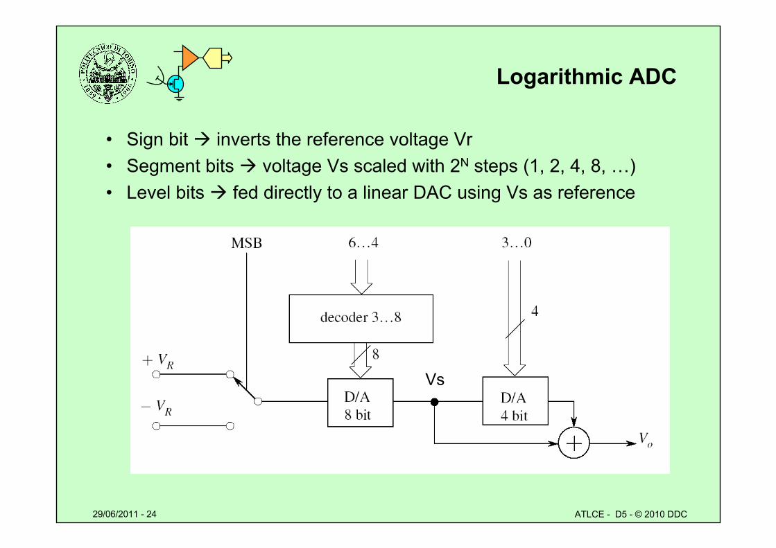
29/06/2011 - 24 ATLCE - D5 - © 2010 DDC
Logarithmic ADC
• Sign bit inverts the reference voltage Vr• Segment bits voltage Vs scaled with 2N steps (1, 2, 4, 8, …)• Level bits fed directly to a linear DAC using Vs as reference
Vs
29/06/2011 - 25 ATLCE - D5 - © 2010 DDC
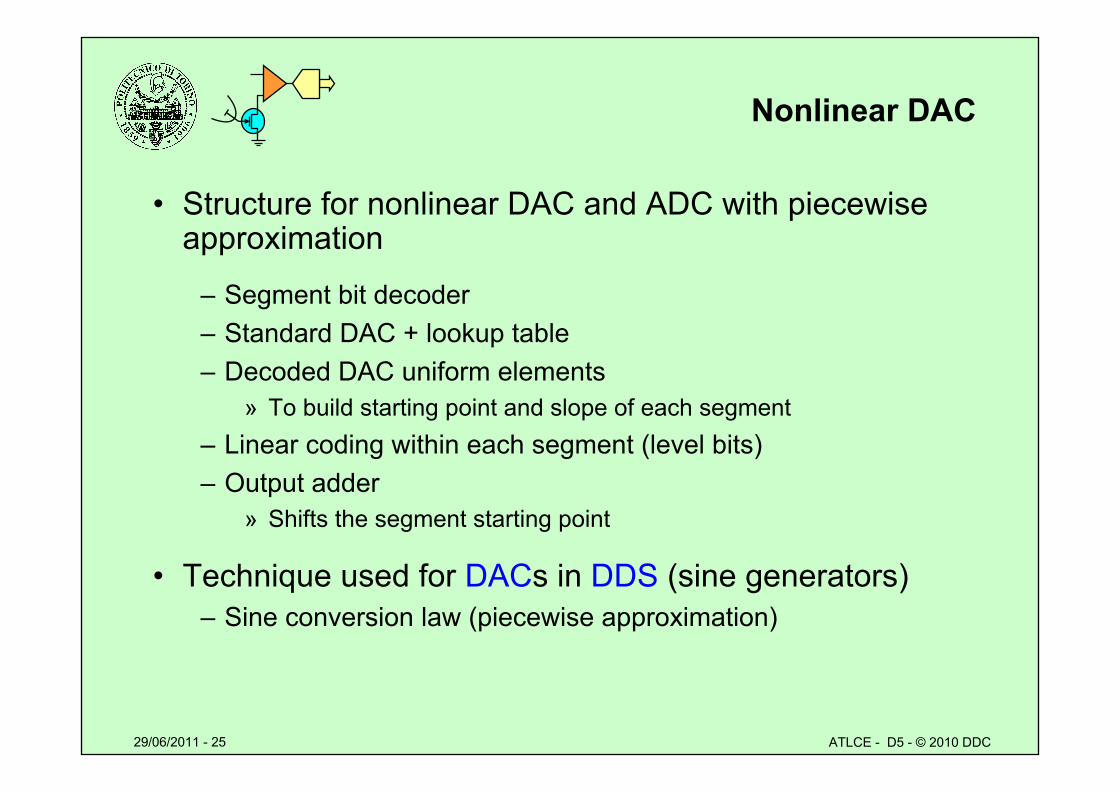
Nonlinear DAC
• Structure for nonlinear DAC and ADC with piecewise approximation
– Segment bit decoder– Standard DAC + lookup table– Decoded DAC uniform elements
» To build starting point and slope of each segment– Linear coding within each segment (level bits)– Output adder
» Shifts the segment starting point
• Technique used for DACs in DDS (sine generators)– Sine conversion law (piecewise approximation)
29/06/2011 - 26 ATLCE - D5 - © 2010 DDC
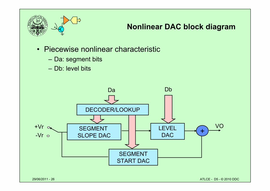
Nonlinear DAC block diagram
• Piecewise nonlinear characteristic– Da: segment bits– Db: level bits
+Vr-Vr
Da
LEVELDAC
Db
SEGMENT SLOPE DAC
DECODER/LOOKUP
SEGMENTSTART DAC
+VO
29/06/2011 - 27 ATLCE - D5 - © 2010 DDC
Lesson D5: special A/D converters
• Logarithmic conversion– Piecewise approximation– A and μ laws– Logarithmic converters
• Differential converters– Sigma-delta converters– Oversampling – Noise shaping
• Waveform encoding and model encoding– Voice LPC– Comparison quality/bit rate
29/06/2011 - 28 ATLCE - D5 - © 2010 DDC
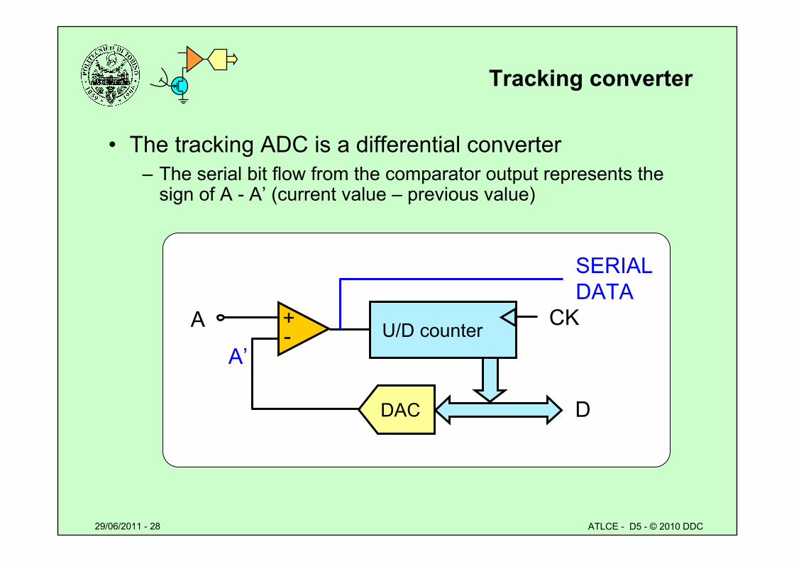
Tracking converter
• The tracking ADC is a differential converter– The serial bit flow from the comparator output represents the
sign of A - A’ (current value – previous value)
-+A
D
A’
DAC
U/D counter CK
SERIALDATA
29/06/2011 - 29 ATLCE - D5 - © 2010 DDC
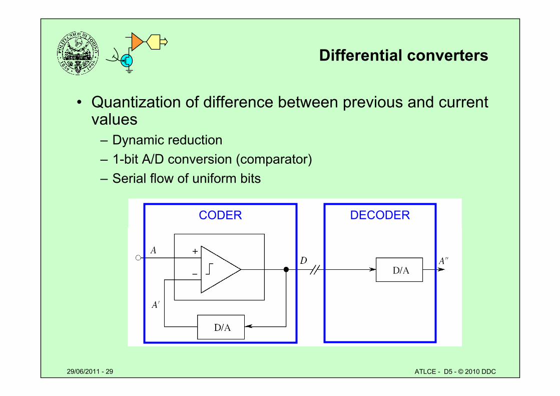
Differential converters
• Quantization of difference between previous and current values
– Dynamic reduction– 1-bit A/D conversion (comparator)– Serial flow of uniform bits
CODER DECODER
29/06/2011 - 30 ATLCE - D5 - © 2010 DDC
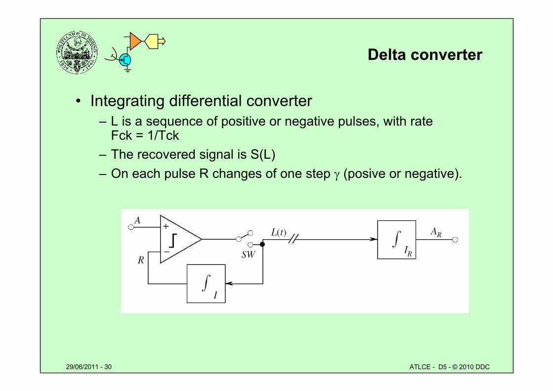
Delta converter
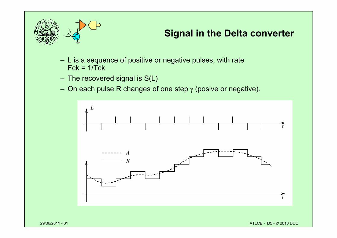
• Integrating differential converter– L is a sequence of positive or negative pulses, with rate
Fck = 1/Tck– The recovered signal is S(L)– On each pulse R changes of one step (posive or negative).
29/06/2011 - 31 ATLCE - D5 - © 2010 DDC
Signal in the Delta converter
– L is a sequence of positive or negative pulses, with rate Fck = 1/Tck
– The recovered signal is S(L)– On each pulse R changes of one step (posive or negative).
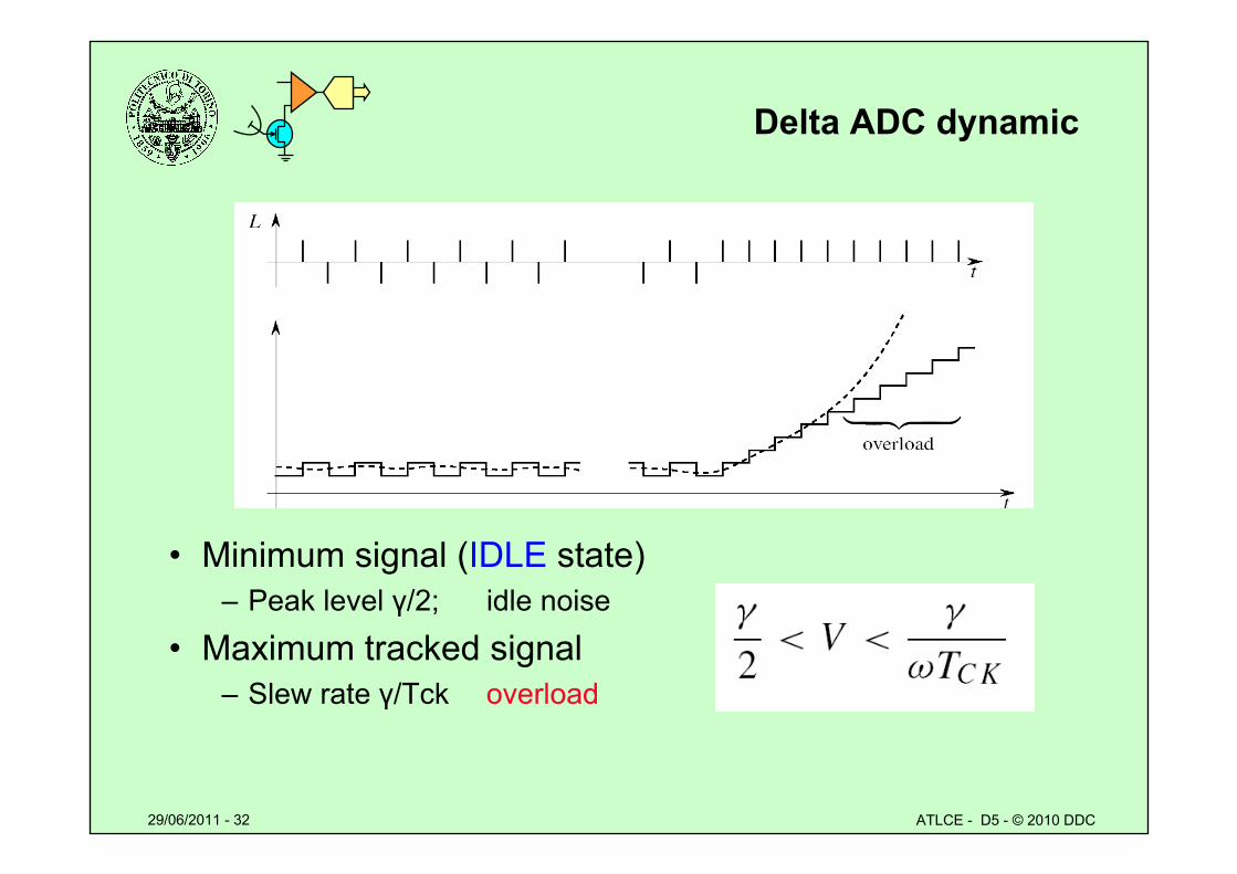
29/06/2011 - 32 ATLCE - D5 - © 2010 DDC
Delta ADC dynamic
• Minimum signal (IDLE state)– Peak level γ/2; idle noise
• Maximum tracked signal– Slew rate γ/Tck overload
29/06/2011 - 33 ATLCE - D5 - © 2010 DDC
Characteristic of Delta (Δ) ADC
• A differential converter– Does not require high precision devices– Does not require formatting of serial output data
• Provides limited dynamic range– Low bound: idle noise – High bound: overload– For a specific SNRq, generates a bit flow with high rate
• Operates in oversampling mode
29/06/2011 - 34 ATLCE - D5 - © 2010 DDC
Oversampling
• Sampling at a rate far higher than the Nyquist limit – Example: 3 kHz audio signal (Nyquist = 6 kS/s)
8 kS/s Nyquist sampling; 1 MS/s Oversampling
• Oversampling sends aliased spectra far from baseband – Reduced aliasing noise, folded from first alias– Relaxed specifications on the anti-alias input filter
• Quantization noise is spread over a wider band (0 - Fs)– Reduced spectral density of quantization noise
• Higher bit rate (more samples/s)– Can be reduced with digital filtering
• Move complexity from analog digital domain
29/06/2011 - 35 ATLCE - D5 - © 2010 DDC
Oversampling vs. Nyquist
X(ω)f
FS10
Main spectrum (baseband) First alias
2FS1
Second alias
X(ω)
f
FS20
First alias
Oversampling
Quantization noise (0-Fs1 band)
Nyquist
Quantization noise (0-Fs2 band)
29/06/2011 - 36 ATLCE - D5 - © 2010 DDC
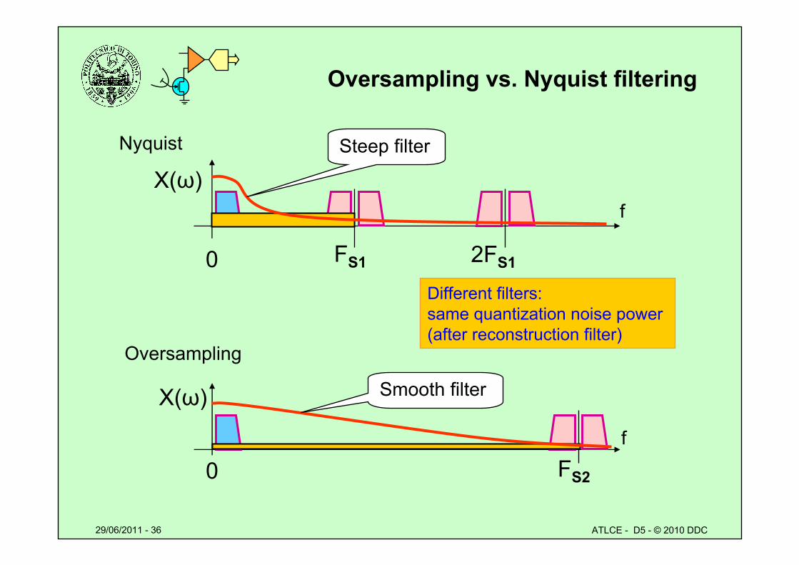
Oversampling vs. Nyquist filtering
X(ω)f
FS10 2FS1
X(ω)
f
FS20
Oversampling
Nyquist Steep filter
Smooth filter
Different filters:same quantization noise power (after reconstruction filter)
29/06/2011 - 37 ATLCE - D5 - © 2010 DDC
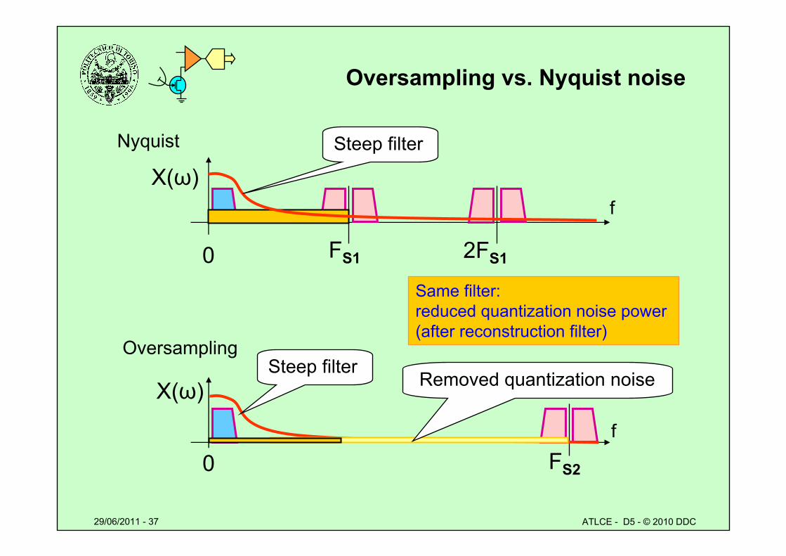
Oversampling vs. Nyquist noise
X(ω)f
FS10 2FS1
Nyquist Steep filter
Same filter:reduced quantization noise power (after reconstruction filter)
X(ω)
f
FS20
Oversampling Steep filter
Removed quantization noise
29/06/2011 - 38 ATLCE - D5 - © 2010 DDC
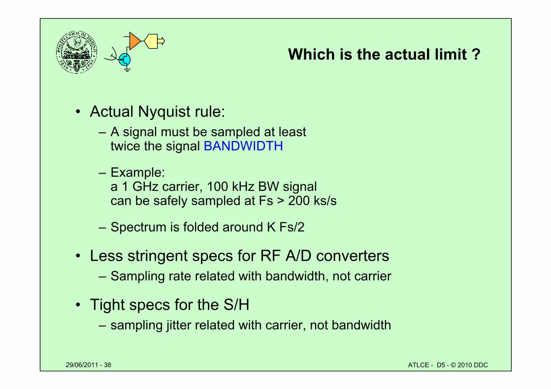
Which is the actual limit ?
• Actual Nyquist rule:– A signal must be sampled at least
twice the signal BANDWIDTH
– Example: a 1 GHz carrier, 100 kHz BW signal can be safely sampled at Fs > 200 ks/s
– Spectrum is folded around K Fs/2
• Less stringent specs for RF A/D converters– Sampling rate related with bandwidth, not carrier
• Tight specs for the S/H– sampling jitter related with carrier, not bandwidth
29/06/2011 - 39 ATLCE - D5 - © 2010 DDC
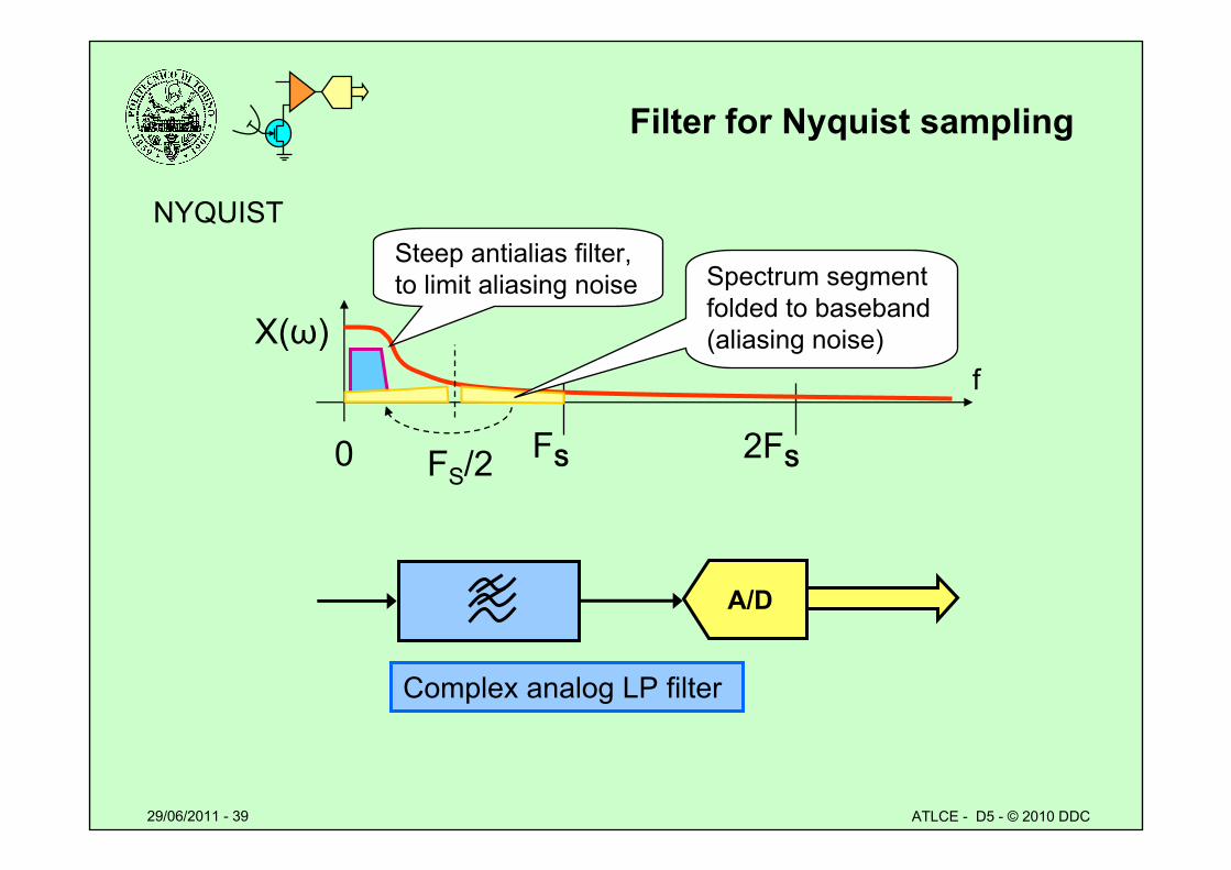
Filter for Nyquist sampling
A/D
Complex analog LP filter
NYQUIST
X(ω)f
FS0 2FSFS/2
Spectrum segment folded to baseband (aliasing noise)
Steep antialias filter, to limit aliasing noise
29/06/2011 - 40 ATLCE - D5 - © 2010 DDC
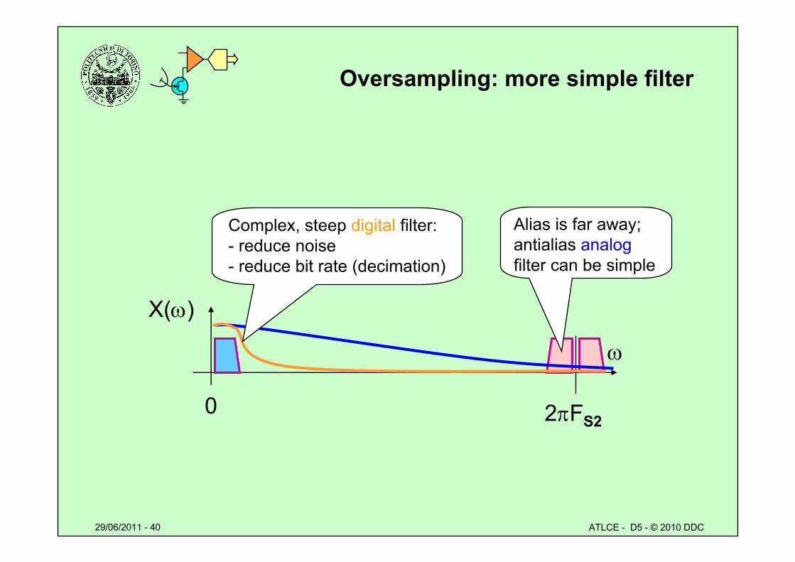
Oversampling: more simple filter
X()
2FS20
Complex, steep digital filter:- reduce noise- reduce bit rate (decimation)
Alias is far away; antialias analogfilter can be simple
29/06/2011 - 41 ATLCE - D5 - © 2010 DDC
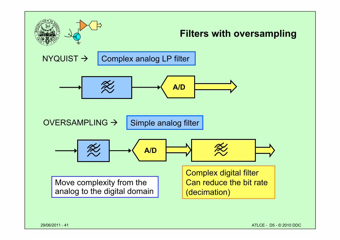
Filters with oversampling
A/D
Simple analog filter
Complex digital filterCan reduce the bit rate (decimation)
NYQUIST
OVERSAMPLING
Complex analog LP filter
A/D
Move complexity from the analog to the digital domain
29/06/2011 - 42 ATLCE - D5 - © 2010 DDC
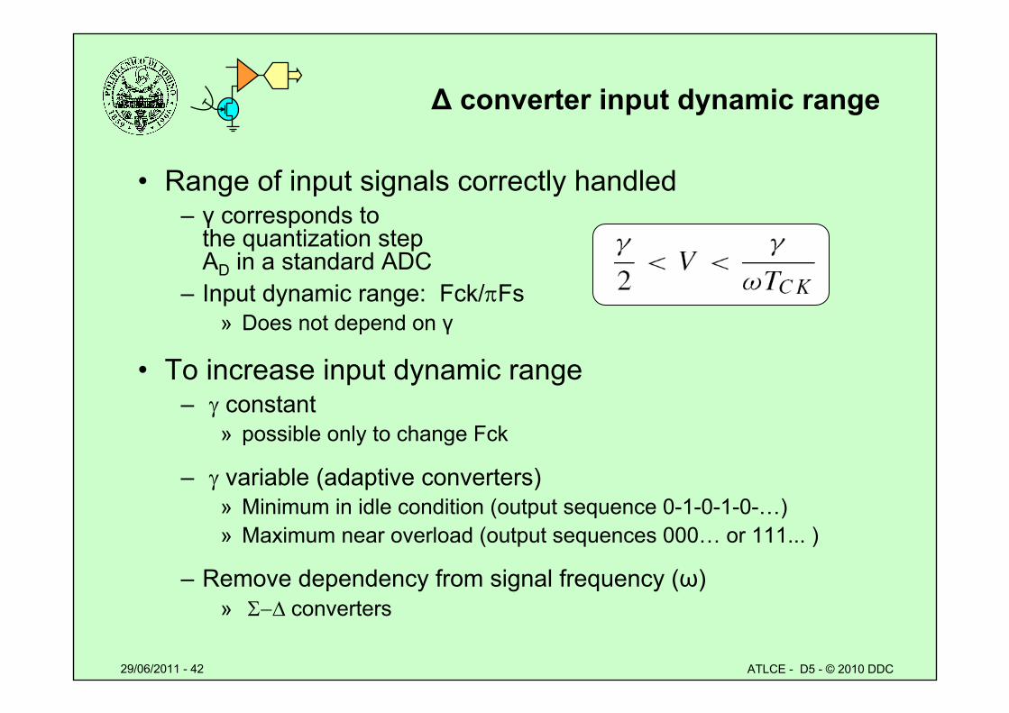
Δ converter input dynamic range
• Range of input signals correctly handled– γ corresponds to
the quantization stepAD in a standard ADC
– Input dynamic range: Fck/Fs» Does not depend on γ
• To increase input dynamic range– constant
» possible only to change Fck
– variable (adaptive converters)» Minimum in idle condition (output sequence 0-1-0-1-0-…)» Maximum near overload (output sequences 000… or 111... )
– Remove dependency from signal frequency (ω)» converters
29/06/2011 - 43 ATLCE - D5 - © 2010 DDC
Numeric example
• Audio signal– Fmax 3 kHz– Sampled 8 ks/s, 8 bit quantization
» Which SNRq ?» Which Fck to obtain the same SNRq with a differential converter?
29/06/2011 - 44 ATLCE - D5 - © 2010 DDC
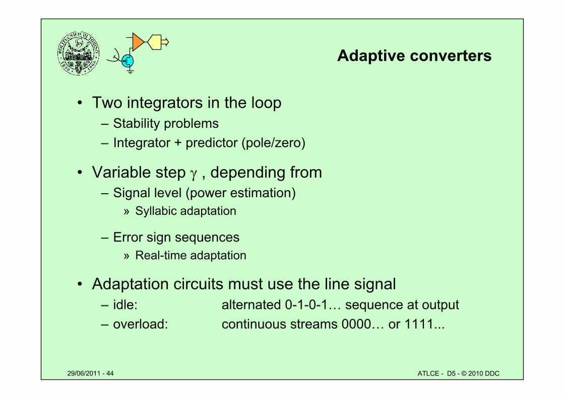
Adaptive converters
• Two integrators in the loop– Stability problems– Integrator + predictor (pole/zero)
• Variable step , depending from – Signal level (power estimation)
» Syllabic adaptation
– Error sign sequences» Real-time adaptation
• Adaptation circuits must use the line signal– idle: alternated 0-1-0-1… sequence at output– overload: continuous streams 0000… or 1111...
29/06/2011 - 45 ATLCE - D5 - © 2010 DDC
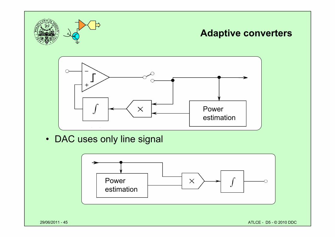
Adaptive converters
• DAC uses only line signal
Powerestimation
Powerestimation
29/06/2011 - 46 ATLCE - D5 - © 2010 DDC
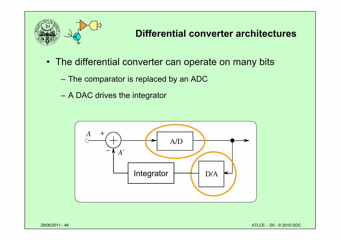
Differential converter architectures
• The differential converter can operate on many bits
– The comparator is replaced by an ADC
– A DAC drives the integrator
Integrator
29/06/2011 - 47 ATLCE - D5 - © 2010 DDC
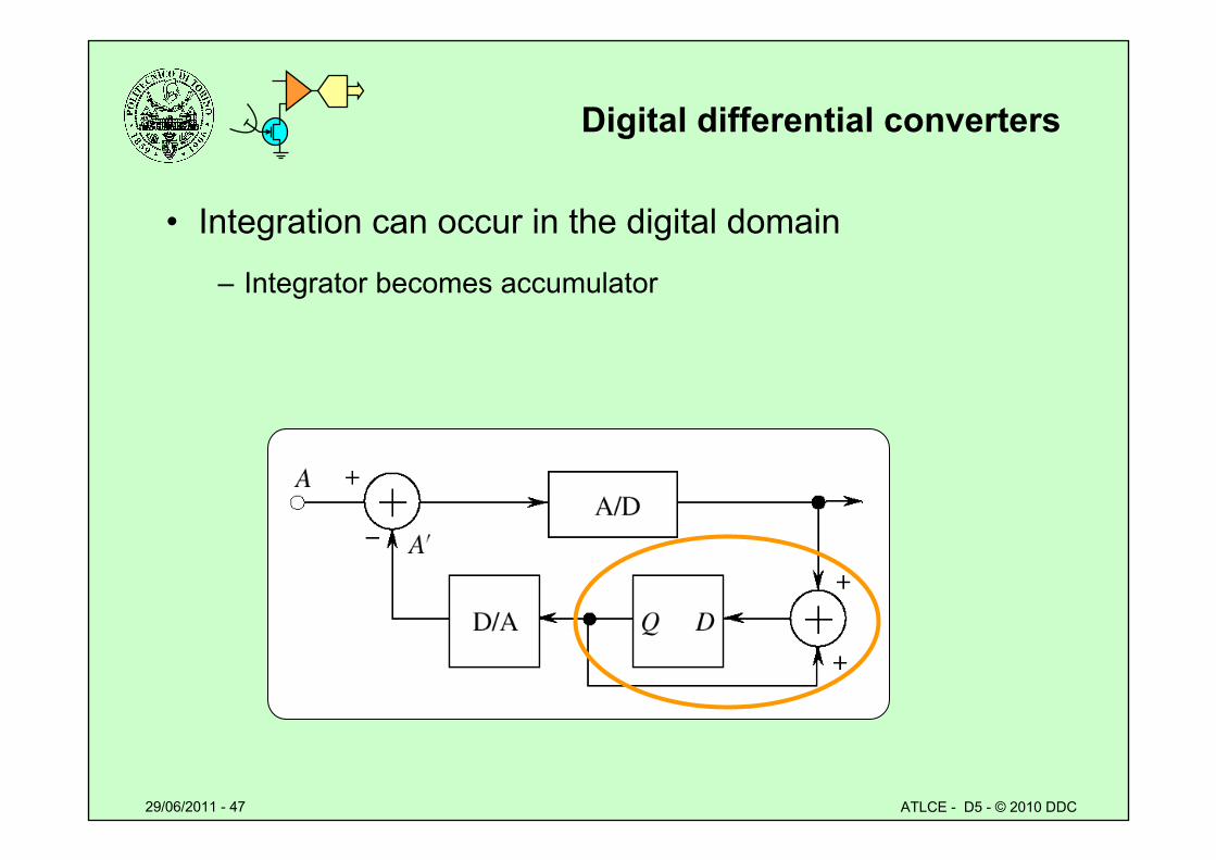
Digital differential converters
• Integration can occur in the digital domain
– Integrator becomes accumulator
29/06/2011 - 48 ATLCE - D5 - © 2010 DDC
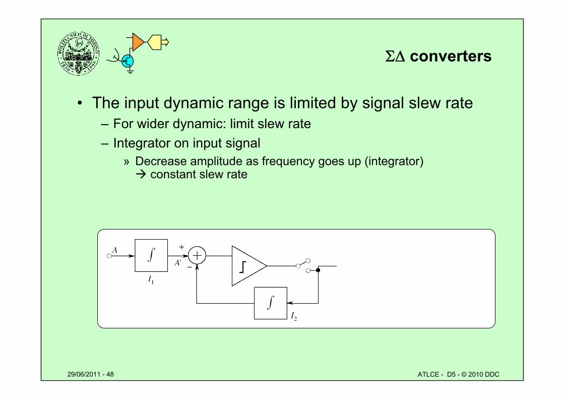
converters
• The input dynamic range is limited by signal slew rate– For wider dynamic: limit slew rate– Integrator on input signal
» Decrease amplitude as frequency goes up (integrator) constant slew rate
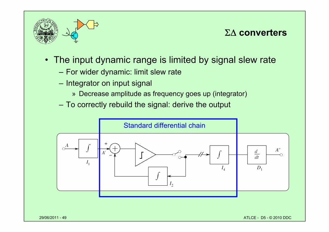
29/06/2011 - 49 ATLCE - D5 - © 2010 DDC
converters
• The input dynamic range is limited by signal slew rate– For wider dynamic: limit slew rate– Integrator on input signal
» Decrease amplitude as frequency goes up (integrator)– To correctly rebuild the signal: derive the output
Standard differential chain
29/06/2011 - 50 ATLCE - D5 - © 2010 DDC
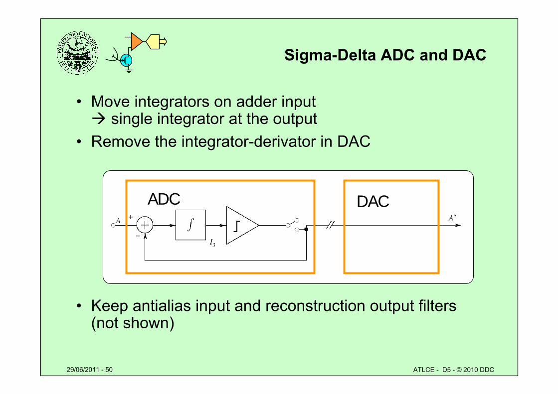
Sigma-Delta ADC and DAC
• Move integrators on adder input single integrator at the output
• Remove the integrator-derivator in DAC
• Keep antialias input and reconstruction output filters (not shown)
ADC DAC
29/06/2011 - 51 ATLCE - D5 - © 2010 DDC
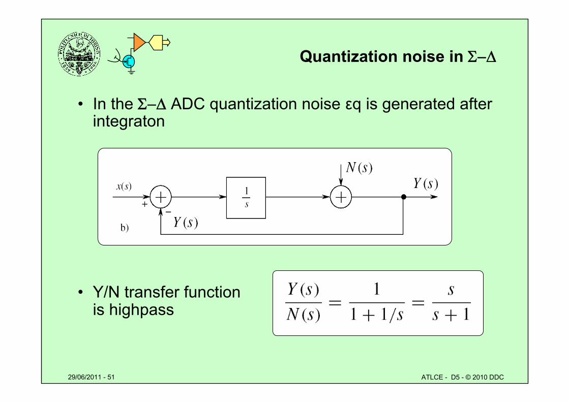
Quantization noise in
• In the ADC quantization noise εq is generated after integraton
• Y/N transfer function is highpass
29/06/2011 - 52 ATLCE - D5 - © 2010 DDC
Noise shaping
• Noise is shifted towards high frequencies
• Noise power spectrum density is higher at high frequencies:
– Noise shaping
• Noise power spectrum density in baseband is reduced
• Further reduction to output noise power– Or simpler reconstruction filter
29/06/2011 - 53 ATLCE - D5 - © 2010 DDC
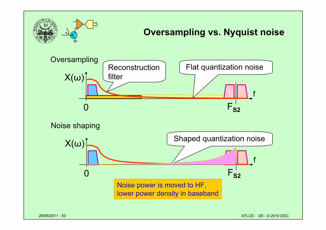
Oversampling vs. Nyquist noise
Noise power is moved to HF, lower power density in baseband
X(ω)
f
FS20
Noise shaping
Shaped quantization noise
X(ω)
f
FS20
Oversampling Reconstruction filter
Flat quantization noise
29/06/2011 - 54 ATLCE - D5 - © 2010 DDC
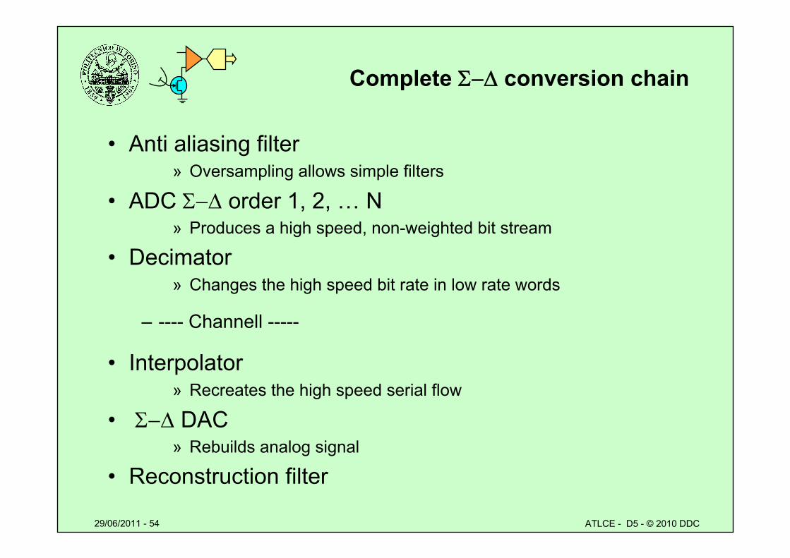
Complete conversion chain
• Anti aliasing filter» Oversampling allows simple filters
• ADC order 1, 2, … N» Produces a high speed, non-weighted bit stream
• Decimator» Changes the high speed bit rate in low rate words
– ---- Channell -----
• Interpolator» Recreates the high speed serial flow
• DAC» Rebuilds analog signal
• Reconstruction filter
29/06/2011 - 55 ATLCE - D5 - © 2010 DDC
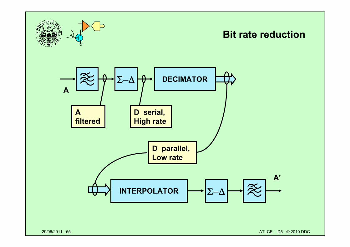
Bit rate reduction
DECIMATOR
INTERPOLATOR
A
A filtered
D serial, High rate
D parallel, Low rate
A’
29/06/2011 - 56 ATLCE - D5 - © 2010 DDC
Lesson D5: special A/D converters
• Logarithmic conversion– Piecewise approximation– A and μ laws– Logarithmic converters
• Differential converters– Sigma-delta converters– Oversampling – Noise shaping
• Waveform encoding and model encoding– Voice LPC– Comparison quality/bit rate

29/06/2011 - 57 ATLCE - D5 - © 2010 DDC
Model encoding vs waveform encoding
• Waveform encoding:– Sequence of number which represent the sequence of values
generated by sampling the time varying signal.– Example: sine tone
» Values of the sine signal at sampling times.
• Model encoding:– Define a “source model”– Model parameters are derived from the signal– The signal is rebuilt from parameters using the model– Example: sine tone
» Model: sine generator» Parameters: amplitude, frequency, and phase» Rebuilt using a properly set signal generator.
29/06/2011 - 58 ATLCE - D5 - © 2010 DDC
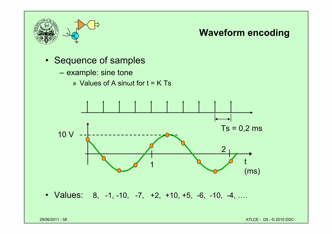
Waveform encoding
• Sequence of samples– example: sine tone
» Values of A sinωt for t = K Ts
• Values: 8, -1, -10, -7, +2, +10, +5, -6, -10, -4, ….
Ts = 0,2 ms
t(ms)
10 V
1
2
29/06/2011 - 59 ATLCE - D5 - © 2010 DDC
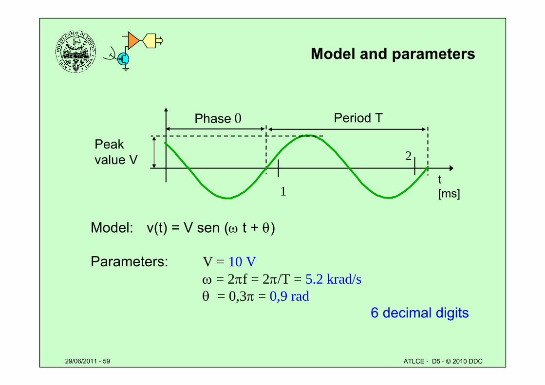
Model and parameters
Model: v(t) = V sen ( t + )
Parameters: V = 10 V = 2f = 2/T = 5.2 krad/s= 0,3 = 0,9 rad
6 decimal digits
Period TPhase
t[ms]1
2Peak value V
29/06/2011 - 60 ATLCE - D5 - © 2010 DDC
SNR for model encoding
• Which factors influence SNR?
• Waveform encoding
– Sampling rate– Resolution of samples (bit number)
• Model encoding
– Model accuracy– Correctness and resolution of parameters
29/06/2011 - 61 ATLCE - D5 - © 2010 DDC
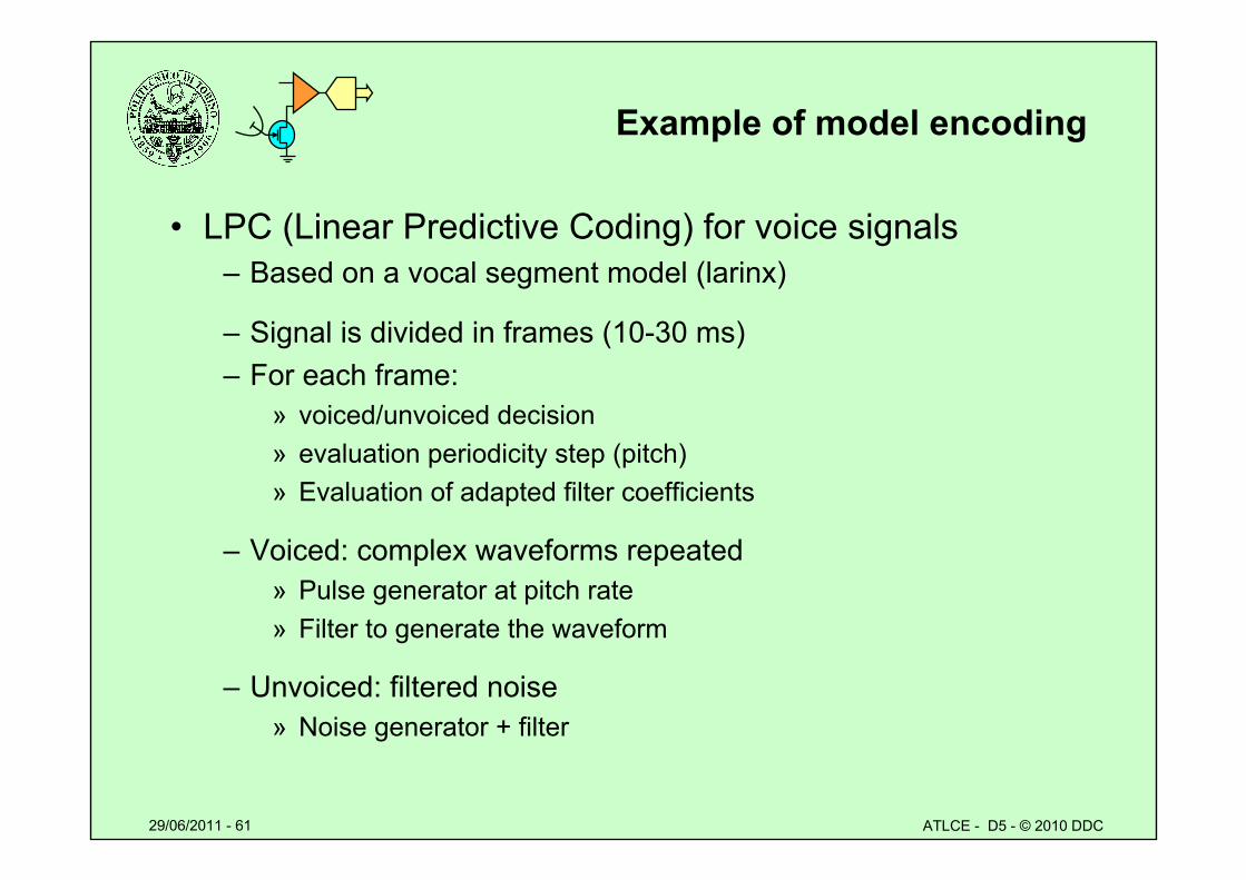
Example of model encoding
• LPC (Linear Predictive Coding) for voice signals– Based on a vocal segment model (larinx)
– Signal is divided in frames (10-30 ms)– For each frame:
» voiced/unvoiced decision» evaluation periodicity step (pitch)» Evaluation of adapted filter coefficients
– Voiced: complex waveforms repeated » Pulse generator at pitch rate» Filter to generate the waveform
– Unvoiced: filtered noise» Noise generator + filter
29/06/2011 - 62 ATLCE - D5 - © 2010 DDC
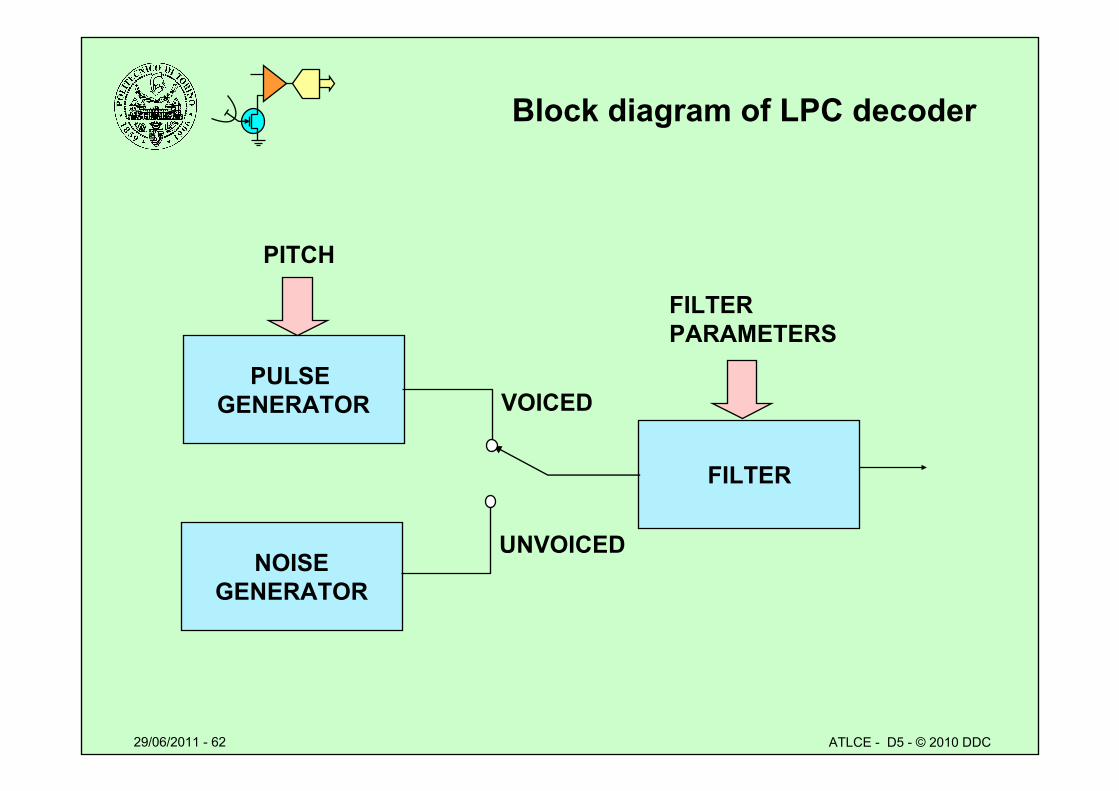
Block diagram of LPC decoder
PULSE GENERATOR
NOISEGENERATOR
FILTER
PITCH
FILTER PARAMETERS
VOICED
UNVOICED
29/06/2011 - 63 ATLCE - D5 - © 2010 DDC
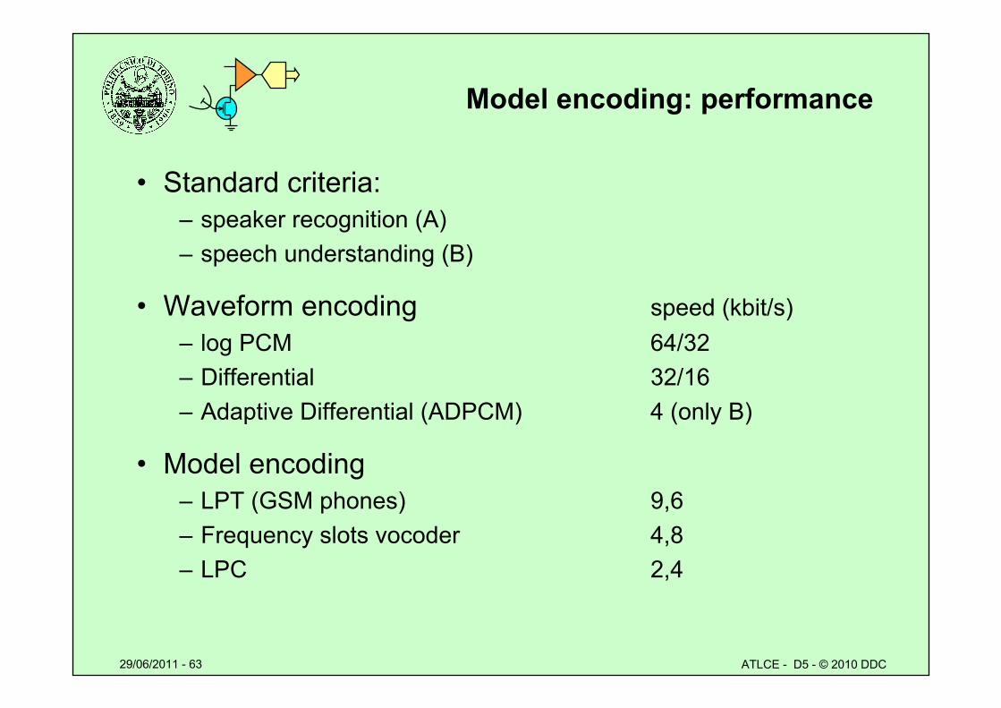
Model encoding: performance
• Standard criteria:– speaker recognition (A)– speech understanding (B)
• Waveform encoding speed (kbit/s)– log PCM 64/32– Differential 32/16 – Adaptive Differential (ADPCM) 4 (only B)
• Model encoding– LPT (GSM phones) 9,6– Frequency slots vocoder 4,8– LPC 2,4
29/06/2011 - 64 ATLCE - D5 - © 2010 DDC
Lesson D5 – final test
• Which are the benefits of logarithmic conversion?
• What happens for signals close to 0 in a log ADC?
• Which are the differences between A and μ log approximations?
• Which parameter controls the dynamic range of a differential ADC?• Explain structure of delta-sigma ADC.
–
• Which are benefits and drawbacks of oversampling?
• Explain noise shaping.
• Which parameters influence S/N for model encoding?
• Describe features of waveform and model encoding techniques.

![EKT104 ANALOG ELECTRONIC CIRCUITS [LITAR ELEKTRONIK ANALOG] BASIC BJT AMPLIFIER (PART II) 1 DR NIK ADILAH HANIN BINTI ZAHRI adilahhanin@unimap.edu.my.](https://static.fdocument.org/doc/165x107/56649ec75503460f94bd3d2c/ekt104-analog-electronic-circuits-litar-elektronik-analog-basic-bjt-amplifier.jpg)