TRUE RMS - EST · TRUE RMS AUTO SENSE LOCK ... Misurazione di resistenza e bassa resistenza ... The...
18
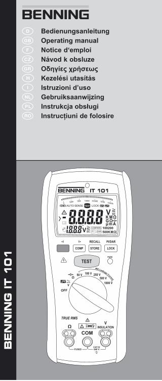
RECALL PI/DAR PASS STORE COMP LOCK TEST COM 1000 V V INSULATION CAT.IV 600 V FUSED 500 V 250 V 100 V 50 V V OFF Ω Ω M Ω Leaka g e C urre n t > 660 V TRUE RMS AUTO SENSE LOCK 100200 500KMΩ COMPARE DAR PI V V KMΩ GΩ μmA 100M 100kM 10Gk 100Gk 100k 0 10M D Bedienungsanleitung Operating manual F Notice d‘emploi Návod k obsluze Οδηγίες χρήσεως H Kezelési utasítás I Istruzioni d’uso Gebruiksaanwijzing Instrukcja obsługi Instrucţiuni de folosire BENNING IT 101
Transcript of TRUE RMS - EST · TRUE RMS AUTO SENSE LOCK ... Misurazione di resistenza e bassa resistenza ... The...
RECALL PI/DAR
PASS
STORECOMP LOCK
TEST
COM
1000 V
VINSULATION
CAT.IV600 VFUSED
500 V250 V100 V50 V
VOFF
Ω
Ω
MΩ Leakage Current
> 660 V
TRUE RMS
AUTO SENSE LOCK
100200500KMΩ
COMPARE
DARP I
V
V
K M ΩG Ωµ m A
100M 100kM 10Gk 100Gk100k010M
D Bedienungsanleitung Operating manualF Notice d‘emploi Návod k obsluze Οδηγίες χρήσεωςH Kezelési utasításI Istruzioni d’uso Gebruiksaanwijzing Instrukcja obsługi Instrucţiuni de folosire
BEN
NIN
G IT 1
01
03/ 2009 BENNING IT 101
D F H I
RECALL PI/DAR
PASS
STORECOMP LOCK
TEST
COM
1000 V
VINSULATION
CAT.IV600 VFUSED
500 V250 V100 V50 V
VOFF
Ω
Ω
MΩ Leakage Current
> 660 V
TRUE RMS
AUTO SENSE LOCK
100200500KMΩ
COMPARE
DARP I
V
V
K M ΩG Ωµ m A
100M 100kM 10Gk 100Gk100k010M
AUTO SENSE LOCK
100200500KMΩ
COMPARE
DARP I
V
V
KMΩGΩµmA
100M 100kM 10Gk 100Gk100k010M
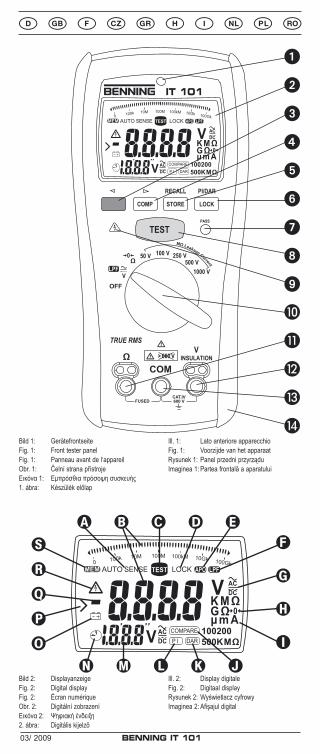
Bild 2: DisplayanzeigeFig. 2: Digital displayFig. 2: Écran numériqueObr. 2: Digitální zobrazení Εικόνα 2: Ψηφιακή ένδειξη2. ábra: Digitális kijelző
Ill. 2: Display digitaleFig. 2: Digitaal displayRysunek 2: Wyświetlacz cyfrowyImaginea 2: Afişajul digital
Bild 1: GerätefrontseiteFig. 1: Front tester panelFig. 1: Panneau avant de l‘appareilObr. 1: Čelní strana přístrojeΕικόνα 1: Εμπρόσθια πρόσοψη συσκευής1. ábra: Készülék előlap
Ill. 1: Lato anteriore apparecchioFig. 1: Voorzijde van het apparaatRysunek 1: Panel przedni przyrząduImaginea 1: Partea frontală a aparatului
L
A
Q
B
P
S
C
O
R
D
N
E
M
F
L
G
K
H
I
J
N
M
03/ 2009 BENNING IT 101
D F H I
RECALL PI/DAR
PASS
STORECOMP LOCK
TEST
COM
1000 V
VINSULATION
CAT.IV600 VFUSED
500 V250 V100 V50 V
VOFF
Ω
Ω
MΩ Leakage Current
> 660 V
TRUE RMS
AUTO SENSE LOCK
100200500KMΩ
COMPARE
DARP I
V
V
K M ΩG Ωµ m A
100M 100kM 10Gk 100Gk100k010M
RECALL PI/DAR
PASS
STORECOMP LOCK
TEST
COM
1000 V
VINSULATION
CAT.IV600 VFUSED
500 V250 V100 V50 V
VOFF
Ω
Ω
MΩ Leakage Current
> 660 V
TRUE RMS
AUTO SENSE LOCK
100200500KMΩ
COMPARE
DARP I
V
V
K M ΩG Ωµ m A
100M 100kM 10Gk 100Gk100k010M
RECALL PI/DAR
PASS
STORECOMP LOCK
TEST
COM
1000 V
VINSULATION
CAT.IV600 VFUSED
500 V250 V100 V50 V
VOFF
Ω
Ω
MΩ Leakage Current
> 660 V
TRUE RMS
AUTO SENSE LOCK
100200500KMΩ
COMPARE
DARP I
V
V
K M ΩG Ωµ m A
100M 100kM 10Gk 100Gk100k010M
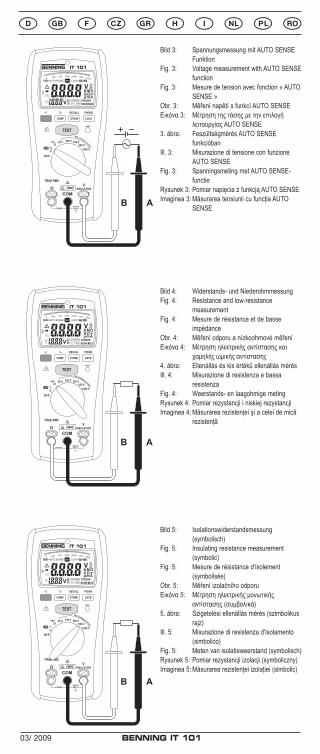
Bild 3: Spannungsmessung mit AUTO SENSE Funktion
Fig. 3: Voltage measurement with AUTO SENSE function
Fig. 3: Mesure de tension avec fonction « AUTO SENSE »
Obr. 3: Měření napětí s funkcí AUTO SENSEΕικόνα 3: Μέτρηση της τάσης με την επιλογή
λειτουργίας AUTO SENSE3. ábra: Feszültségmérés AUTO SENSE
funkcióbanIll. 3: Misurazione di tensione con funzione
AUTO SENSEFig. 3: Spanningsmeting met AUTO SENSE-
functieRysunek 3: Pomiar napięcia z funkcją AUTO SENSEImaginea 3: Măsurarea tensiunii cu funcţia AUTO
SENSE
Bild 4: Widerstands- und Niederohmmessung Fig. 4: Resistance and low-resistance
measurementFig. 4: Mesure de résistance et de basse
impédanceObr. 4: Měření odporu a nízkoohmové měřeníΕικόνα 4: Μέτρηση ηλεκτρικής αντίστασης και
χαμηλής ωμικής αντίστασης4. ábra: Ellenállás és kis értékű ellenállás mérésIll. 4: Misurazione di resistenza e bassa
resistenzaFig. 4: Weerstands- en laagohmige metingRysunek 4: Pomiar rezystancji i niskiej rezystancjiImaginea 4: Măsurarea rezistenţei şi a celei de mică
rezistenţă
Bild 5: Isolationswiderstandsmessung (symbolisch)
Fig. 5: Insulating resistance measurement (symbolic)
Fig. 5: Mesure de résistance d‘isolement (symbolisée)
Obr. 5: Měření izolačního odporuΕικόνα 5: Μέτρηση ηλεκτρικής μονωτικής
αντίστασης (συμβολικά)5. ábra: Szigetelési ellenállás mérés (szimbolikus
rajz)Ill. 5: Misurazione di resistenza d‘isolamento
(simbolico)Fig. 5: Meten van isolatieweerstand (symbolisch)Rysunek 5: Pomiar rezystancji izolacji (symboliczny)Imaginea 5: Măsurarea rezistenţei izolaţiei (simbolic)
03/ 2009 BENNING IT 101
D F H I
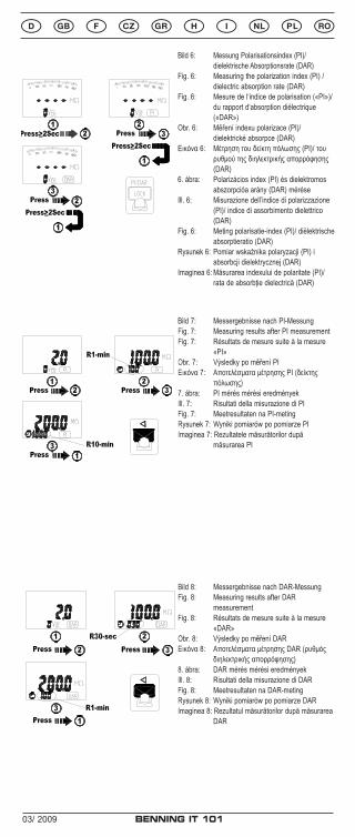
Bild 7: Messergebnisse nach PI-MessungFig. 7: Measuring results after PI measurement Fig. 7: Résultats de mesure suite à la mesure
«PI»Obr. 7: Výsledky po měření PIΕικόνα 7: Αποτελέσματα μέτρησης PI (δείκτης
πόλωσης) 7. ábra: PI mérés mérési eredményekIll. 7: Risultati della misurazione di PIFig. 7: Meetresultaten na PI-metingRysunek 7: Wyniki pomiarów po pomiarze PIImaginea 7: Rezultatele măsurătorilor după
măsurarea PI
Bild 8: Messergebnisse nach DAR-MessungFig. 8: Measuring results after DAR
measurement Fig. 8: Résultats de mesure suite à la mesure
«DAR»Obr. 8: Výsledky po měření DARΕικόνα 8: Αποτελέσματα μέτρησης DAR (ρυθμός
διηλεκτρικής απορρόφησης) 8. ábra: DAR mérés mérési eredményekIll. 8: Risultati della misurazione di DARFig. 8: Meetresultaten na DAR-metingRysunek 8: Wyniki pomiarów po pomiarze DARImaginea 8: Rezultatul măsurătorilor după măsurarea
DAR
7
Using the Compare function
1. Before starting the insulation test : Press the COMP button to select the compare value among 100kΩ,200kΩ,500kΩ,1MΩ,2MΩ,5MΩ,10MΩ,20MΩ, 50MΩ,100MΩ,200MΩ and 500MΩ.
2. If the measured value is greater than the selected compare value, the green Pass indicator will be turned on.
Measuring PI/DAR
PI(Polarization Index)=R10-min/R1-min DAR(Dielectric Absorption Rations)=R1-min/R30-sec where R10-min : the insulation resistance measured at the 10 minute after pressing the TEST button. R1-min : the insulation resistance measured at the 1 minute after pressing the TEST button. R30-sec : the insulation resistance measured at the 30 second after pressing the TEST button.
8
The measured values after the PI test PI=R10-min/R1-min
The measured values after the DAR test DAR=R1-min/R30-sec
If the reading for DAR is bigger than 1.3 or PI is bigger than 2, it indicate a good insulation quality. When the measured resistance is higher than the maximum range, the screen will display "Err" symbol for PI/DAR value. TEST button : Press once to start/interrupt the PI /DAR test.
Blue button : Press once during the PI/DAR test to display the time left of the test.
Bild 6: Messung Polarisationsindex (PI)/ dielektrische Absorptionsrate (DAR)
Fig. 6: Measuring the polarization index (PI) / dielectric absorption rate (DAR)
Fig. 6: Mesure de l‘indice de polarisation («PI»)/ du rapport d‘absorption diélectrique («DAR»)
Obr. 6: Měření indexu polarizace (PI)/ dielektrické absorpce (DAR)
Εικόνα 6: Μέτρηση του δείκτη πόλωσης (PI)/ του ρυθμού της διηλεκτρικής απορρόφησης (DAR)
6. ábra: Polarizácios index (PI) és dielektromos abszorpcióa arány (DAR) mérése
Ill. 6: Misurazione dell’indice di polarizzazione (PI)/ indice di assorbimento dielettrico (DAR)
Fig. 6: Meting polarisatie-index (PI)/ diëlektrische absorptieratio (DAR)
Rysunek 6: Pomiar wskaźnika polaryzacji (PI) i absorbcji dielektrycznej (DAR)
Imaginea 6: Măsurarea indexului de polaritate (PI)/ rata de absorbţie dielectrică (DAR)
03/ 2009 BENNING IT 101
D F H I
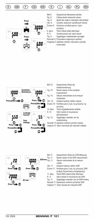
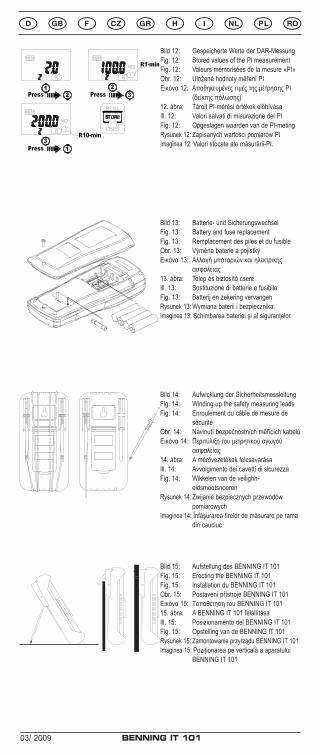
Bild 10: Gespeicherte Werte der Isolationsmessung
Fig. 10: Stored values of the insulation measurement
Fig. 10: Valeurs mémorisées de la mesure d‘isolement
Obr. 10: Uložené hodnoty měření izolaceΕικόνα 10: Αποθηκευμένες τιμές της μέτρησης της
μόνωσης10. ábra: Tárolt szigetelésmérési értékekIll. 10: Valori salvati di misurazione
dell‘isolamentoFig. 10: Opgeslagen waarden van de
isolatiemetingRysunek 10: Zapisane wartości pomiaru izolacjiImaginea 10: Valori memorate ale măsurării izolaţiei.
Bild 11: Gespeicherte Werte der DAR-MessungFig. 11: Stored values of the DAR measurementFig. 11: Valeurs mémorisées de la mesure
«DAR»Obr. 11: Uložené hodnoty měření DARΕικόνα 11: Αποθηκευμένες τιμές της μέτρησης DAR
(ρυθμός διηλεκτρικής απορρόφησης)11. ábra: Tárolt DAR-mérési érték előhívásaIll. 11: Valori salvati di misurazione del DARFig. 11: Opgeslagen waarden van de DAR-metingRysunek 11: Zapisanych wartości pomiarów DARImaginea 11: Valori stocate ale măsurării-DAR.
9
Using the Store function Store/Recall button The screen will be flashing MEM symbol and the number of stored data twice when the Store/Recall button is pressed. 1. Press once to store the voltage value during voltage test 2. Press once to store the PI/ DAR, insulation or Earth-bond resistance value when the individual test is completed. 3. The memory is divided into five segments,each segments has 100 maximum data. The method to store the data is first in /first out when the memory is full. Table: The stored values of the individual test
segments
Items Voltage Earth-Bond
resistance
Insulation resistance 50~1000V
DAR PI
1 Voltage Resistance Resistance DAR value PI value
2 Leakage current R30-sec R1-min
3 Test voltage R1-min R10-min
Search the stored value under RECALL mode
NOTE : Press the Store/Recall button ≧5 sec to clear the stored data. The screen will be flashing MEM symbol and “ cLr ” on reading twice. Using the Recall function Press the Store/Recall button ≧2 sec to enter/exit the RECALL mode. If the memory is empty, the meter will display the “nOnE ” symbol.
10
Read the stored value of insulation test under RECALL mode
Read the stored value of DAR test under RECALL mode Press the PI/DAR button ≧ 2 sec to choose the DAR function, and Press the Store/Recall button ≧ 2 sec to enter the RECALL mode.
10
Read the stored value of insulation test under RECALL mode
Read the stored value of DAR test under RECALL mode Press the PI/DAR button ≧ 2 sec to choose the DAR function, and Press the Store/Recall button ≧ 2 sec to enter the RECALL mode.
Bild 9: Gespeicherte Messwerte aufrufenFig. 9: Calling stored measured values Fig. 9: Appel des valeurs mesurées mémoriséesObr. 9: Vyvolání uložených naměřených hodnotΕικόνα 9: Ανάκληση αποθηκευμένων τιμών
μέτρησης9. ábra: Tárolt mérési érték előhívásalIll. 9: Visualizzazione dei valori salvatiFig. 9: Opgeslagen meetwaarden opvragenRysunek 9: Przywołanie zapisanych wartościImaginea 9: Apelarea valorilor măsurate şi stocate
(memorate).
03/ 2009 BENNING IT 101
D F H I
Bild 12: Gespeicherte Werte der DAR-MessungFig. 12: Stored values of the PI measurementFig. 12: Valeurs mémorisées de la mesure «PI»Obr. 12: Uložené hodnoty měření PIΕικόνα 12: Αποθηκευμένες τιμές της μέτρησης PI
(δείκτης πόλωσης)12. ábra: Tárolt PI-mérési értékek előhívásaIll. 12: Valori salvati di misurazione del PIFig. 12: Opgeslagen waarden van de PI-metingRysunek 12: Zapisanych wartości pomiarów PIImaginea 12: Valori stocate ale măsurării-PI.
Read the stored value of PI test under RECALL mode Press the PI/DAR button ≧2 sec to choose the PI function, and Press the Store/Recall button ≧2 sec to enter the RECALL mode.
Auto Power Off (Battery Saver)
Restore power by switching rotor or pressing any button. Auto Backlight The backlight is automatically turned on at dark environment. BUZZER The Meter beeps once for every valid key-press, and beeps twice for every invalid key-press.
RECALL PI/DAR
PASS
STORECOMP LOCK
TEST
COM
1000 V
VINSULATION
CAT.IV600 VFUSED
500 V250 V100 V50 V
VOFF
Ω
Ω
MΩ Leakage Current
> 660 V
TRUE RMS
AUTO SENSE LOCK
100200500KMΩ
COMPARE
DARP I
V
V
K M ΩG Ωµ m A
100M 100kM 10Gk 100Gk100k010M
Bild 13: Batterie- und SicherungswechselFig. 13: Battery and fuse replacement Fig. 13: Remplacement des piles et du fusibleObr. 13: Výměna baterie a pojistkyΕικόνα 13: Αλλαγή μπαταριών και ηλεκτρικής
ασφάλειας13. ábra: Telep és biztosító csereIll. 13: Sostituzione di batterie e fusibileFig. 13: Batterij en zekering vervangenRysunek 13: Wymiana baterii i bezpiecznikaImaginea 13: Schimbarea bateriei şi al siguranţelor
Bild 14: Aufwicklung der SicherheitsmessleitungFig. 14: Winding up the safety measuring leads Fig. 14: Enroulement du câble de mesure de
sécuritéObr. 14: Navinutí bezpečnostních měřících kabelůΕικόνα 14: Περιτύλιξη του μετρητικoύ αγωγού
ασφαλείας14. ábra: A mérővezetékek felcsavarásaIll. 14: Avvolgimento dei cavetti di sicurezzaFig. 14: Wikkelen van de veilighh-
eidsmeetsnoerenRysunek 14: Zwijanie bezpiecznych przewodów
pomiarowychImaginea 14: Înfăşurarea firelor de măsurare pe rama
din cauciuc
Bild 15: Aufstellung des BENNING IT 101Fig. 15: Erecting the BENNING IT 101 Fig. 15: Installation du BENNING IT 101Obr. 15: Postavení přístroje BENNING IT 101Εικόνα 15: Τοποθέτηση του BENNING IT 10115. ábra: A BENNING IT 101 felállításaIll. 15: Posizionamento del BENNING IT 101Fig. 15: Opstelling van de BENNING IT 101Rysunek 15: Zamontowanie przyrządu BENNING IT 101Imaginea 15: Poziţionarea pe verticală a aparatului
BENNING IT 101
03/ 2009 BENNING IT 101
12
Operating instructions BENNING IT 101
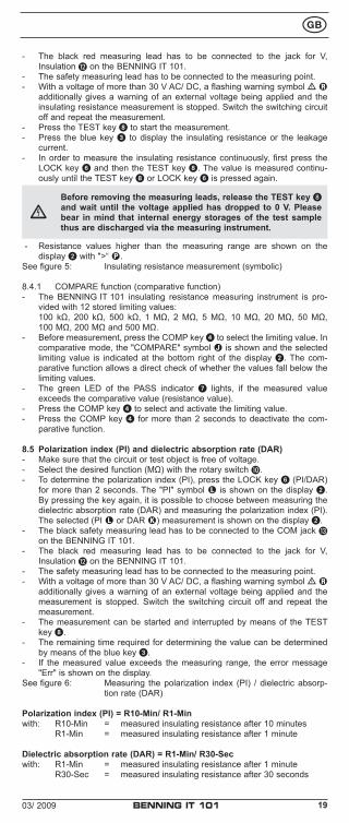
Insulation and resistance measuring instrument for: - Insulating resistance measurements - Low-resistance measurements - Resistance measurements - Direct voltage measurements - Alternating voltage measurements - Measuring/ calculating the polarization index (PI) - Measuring/ calculating the dielectric absorption rate (DAR)
Contents1. User notes2. Safety note3. Scope of delivery4. Description of appliance tester5. General information6. Ambient conditions7. Electrical specifications8. Measuring with the BENNING IT 1019. Maintenance10. Application of rubber protection frame11. Environmental note
1. User notesThese operating instructions are intended for
- qualified electricians, competent persons and- electrotechnically trained persons
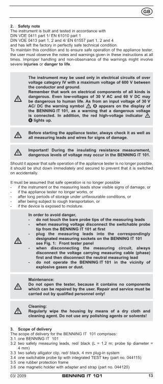
The BENNING IT 101 is intended for making measurements in dry environment. It must not be used in power circuits with a nominal voltage higher than 600 V DC/ AC (more details in Section 6. “Ambient conditions”).The following symbols are used in these operating instructions and on the BENNING IT 101:
Warning of electrical danger!Indicates instructions which must be followed to avoid danger to persons.
Important, comply with the documentation!This symbol indicates that the stipulations in the operating instructions must be followed in order to avoid danger.
This symbol on the BENNING IT 101 means that the BENNING IT 101 is totally insulated (protection class II).
This warning symbol indicates that the BENNING IT 101 must not be used in distribution systems with voltages higher than 600 V.
This symbol on the BENNING IT 101 means that the BENNING IT 101 complies with the EU directives.
This symbol appears on the display to indicate a discharged battery.
This symbol on the BENNING IT 101 indicates the built-in fuses
(DC) direct current or (AC) alternating current
Earth (voltage to ground)
At the end of product life, dispose of the unserviceable device via appropriate collecting facilities provided in your community.
03/ 2009 BENNING IT 101
13
2. Safety noteThe instrument is built and tested in accordance withDIN VDE 0411 part 1/ EN 61010 part 1DIN VDE 0413 part 1, 2 and 4/ EN 61557 part 1, 2 and 4and has left the factory in perfectly safe technical condition.To maintain this condition and to ensure safe operation of the appliance tester, the user must observe the notes and warnings given in these instructions at all times. Improper handling and non-observance of the warnings might involve severe injuries or danger to life.
The instrument may be used only in electrical circuits of over voltage category IV with a maximum voltage of 600 V between the conductor and ground.Remember that work on electrical components of all kinds is dangerous. Even low-voltages of 30 V AC and 60 V DC may be dangerous to human life. As from an input voltage of 30 V AC/ DC the warning symbol R appears on the display of the BENNING IT 101, as a warning that a dangerous voltage is connected. In addition, the red high-voltage indicator 9 lights up.
Before starting the appliance tester, always check it as well as all measuring leads and wires for signs of damage.
Important! During the insulating resistance measurement, dangerous levels of voltage may occur in the BENNING IT 101.
Should it appear that safe operation of the appliance tester is no longer possible, it should be shut down immediately and secured to prevent that it is switched on accidentally.
It must be assumed that safe operation is no longer possible- if the instrument or the measuring leads show visible signs of damage, or- if the appliance tester no longer works, or- after long periods of storage under unfavourable conditions, or- after being subject to rough transportation, or- if the device is exposed to moisture.
In order to avoid danger,- do not touch the bare probe tips of the measuring leads- when measuring voltage disconnect the switchable probe
tip from the BENNING IT 101 at first- plug the measuring leads into the correspondingly
designated measuring sockets on the BENNING IT 101 see Fig. 1: Front tester panel- when disconnecting the measuring circuit, always
disconnect the voltage carrying measuring cable (phase) first and then disconnect the neutral measuring lead
- do not operate the BENNING IT 101 in the vicinity of explosive gases or dust.
Maintenance:Do not open the tester, because it contains no components which can be repaired by the user. Repair and service must be carried out by qualified personnel only!
Cleaning:Regularly wipe the housing by means of a dry cloth and cleaning agent. Do not use any polishing agents or solvents!
3. Scope of deliveryThe scope of delivery for the BENNING IT 101 comprises:3.1 one BENNING IT 1013.2 two safety measuring leads, red/ black (L = 1.2 m; probe tip diameter =
4 mm)3.3 two safety alligator clip, red/ black, 4 mm plug-in system3.4 one switchable probe tip with integrated TEST key (part no. 044115)3.5 one rubber protection frame3.6 one magnetic holder with adapter and strap (part no. 044120)
03/ 2009 BENNING IT 101
14
3.7 one compact protective pouch3.8 four mignon batteries 1.5 V/ type AA according to IEC LR6 and one fuse
(fitted in unit as initial equipment),3.9 one operating manual
Parts subject to wear:- The BENNING IT 101 contains a fuse as protection against overload:
One fuse, nominal current rating 315 mA (1000 V), 10 kA, FF, D = 6.3 mm, L = 32 mm (part no. 757213)
- The BENNING IT 101 is powered by four mignon batteries 1.5 V/ type AA according to IEC LR6.
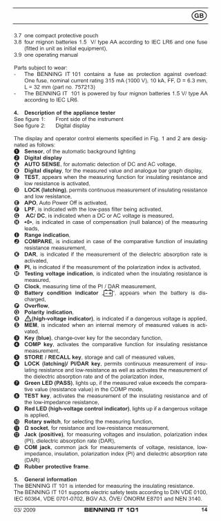
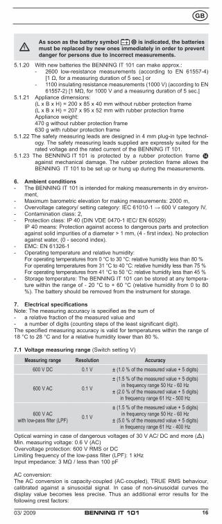
4. Description of the appliance testerSee figure 1: Front side of the instrumentSee figure 2: Digital display
The display and operator control elements specified in Fig. 1 and 2 are desig-nated as follows:1 Sensor, of the automatic background lighting2 Digital displayA AUTO SENSE, for automatic detection of DC and AC voltage,B Digital display, for the measured value and analogue bar graph display,C TEST, appears when the measuring function for insulating resistance and
low resistance is activated,D LOCK (latching), permits continuous measurement of insulating resistance
and low resistance,E APO, Auto Power Off is activated,F LPF, is indicated with the low-pass filter being activated,G AC/ DC, is indicated when a DC or AC voltage is measured,H , is indicated in case of compensation (null balance) of the measuring
leads,I< Range indication,J COMPARE, is indicated in case of the comparative function of insulating
resistance measurement,K DAR, is indicated if the measurement of the dielectric absorption rate is
activated,L PI, is indicated if the measurement of the polarization index is activated,M Testing voltage indication, is indicated when the insulating resistance is
measured,N Clock, measuring time of the PI / DAR measurement,O Battery condition indicator „ “, appears when the battery is dis-
charged,P Overflow, Q Polarity indication,R (high-voltage indicator), is indicated if a dangerous voltage is applied,S MEM, is indicated when an internal memory of measured values is acti-
vated,3 Key (blue), change-over key for the secondary function,4 COMP key, activates the comparative function for insulating resistance
measurement,5 STORE / RECALL key, storage and call of measured values,6 LOCK (latching)/ PI/DAR key, permits continuous measurement of insu-
lating resistance and low-resistance as well as activates the measurement of the dielectric absorption rate and of the polarization index,
7 Green LED (PASS), lights up, if the measured value exceeds the compara-tive value (resistance value) in the COMP mode,
8 TEST key, activates the measurement of the insulating resistance and of the low-impedance resistance,
9 Red LED (high-voltage control indicator), lights up if a dangerous voltage is applied,
J Rotary switch, for selecting the measuring function,K Ω socket, for resistance and low-resistance measurement,L Jack (positive), for measuring voltages and insulation, polarization index
(PI), dielectric absorption rate (DAR),M COM jack, common jack for measurements of voltage, resistance, low-
impedance, insulation, polarization index (PI) and dielectric absorption rate (DAR)
N Rubber protective frame.
5. General informationThe BENNING IT 101 is intended for measuring the insulating resistance.The BENNING IT 101 supports electric safety tests according to DIN VDE 0100, IEC 60364, VDE 0701-0702, BGV A3, ÖVE/ ÖNORM E8701 and NEN 3140.
03/ 2009 BENNING IT 101
15
Preset limiting values make it easier to evaluate the test.
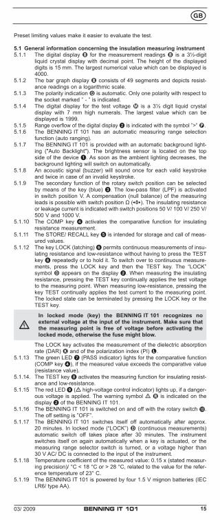
5.1 General information concerning the insulation measuring instrument5.1.1 The digital display B for the measurement readings B is a 3½-digit
liquid crystal display with decimal point. The height of the displayed digits is 15 mm. The largest numerical value which can be displayed is 4000.
5.1.2 The bar graph display B consists of 49 segments and depicts resist-ance readings on a logarithmic scale.
5.1.3 The polarity indication Q is automatic. Only one polarity with respect to the socket marked ” - ” is indicated.
5.1.4 The digital display for the test voltage M is a 3½ digit liquid crystal display with 7 mm high numerals. The largest value which can be displayed is 1999.
5.1.5 Range overflow of the digital display 2 is indicated with the symbol ”>” P.5.1.6 The BENNING IT 101 has an automatic measuring range selection
function (auto ranging).5.1.7 The BENNING IT 101 is provided with an automatic background light-
ing ("Auto Backlight"). The brightness sensor is located on the top side of the device 1. As soon as the ambient lighting decreases, the background lighting will switch on automatically.
5.1.8 An acoustic signal (buzzer) will sound once for each valid keystroke and twice in case of an invalid keystroke.
5.1.9 The secondary function of the rotary switch position can be selected by means of the key (blue) 3. The low-pass filter (LPF) is activated in switch position V. A compensation (null balance) of the measuring leads is possible with switch position Ω ( ). The insulating resistance or leakage current is indicated with switch positions 50 V/ 100 V/ 250 V/ 500 V and 1000 V.
5.1.10 The COMP key 4 activates the comparative function for insulating resistance measurement.
5.1.11 The STORE/ RECALL key 5 is intended for storage and call of meas-ured values.
5.1.12 The key LOCK (latching) 6 permits continuous measurements of insu-lating resistance and low-resistance without having to press the TEST key 8 repeatedly or to hold it. To switch over to continuous measure-ments, press the LOCK key and then the TEST key. The “LOCK” symbol D appears on the display 2. When measuring the insulating resistance, pressing the TEST key continually applies the test voltage to the measuring point. When measuring low-resistance, pressing the key TEST continually applies the test current to the measuring point. The locked state can be terminated by pressing the LOCK key or the TEST key.
In locked mode (key) the BENNING IT 101 recognizes no external voltage at the input of the instrument. Make sure that the measuring point is free of voltage before activating the locked mode, otherwise the fuse might blow.
The LOCK key activates the measurement of the dielectric absorption rate (DAR) K and of the polarization index (PI) L.
5.1.13 The green LED 7 (PASS indicator) lights for the comparative function (COMP key 4), if the measured value exceeds the comparative value (resistance value).
5.1.14. The TEST key 8 activates the measuring function for insulating resist-ance and low-resistance.
5.1.15 The red LED 9 ( high-voltage control indicator) lights up, if a danger-ous voltage is applied. The warning symbol R is indicated on the display 2 of the BENNING IT 101.
5.1.16 The BENNING IT 101 is switched on and off with the rotary switch J. The off setting is ”OFF”.
5.1.17 The BENNING IT 101 switches itself off automatically after approx. 20 minutes. In locked mode (“LOCK”) D (continuous measurements) automatic switch off takes place after 30 minutes. The instrument switches itself on again automatically when a key is actuated, or the measuring range selector switch is turned, or a voltage higher than 30 V AC/ DC is connected to the input of the instrument.
5.1.18 Temperature coefficient of the measured value: 0.15 x (stated measur-ing precision)/ °C < 18 °C or > 28 °C, related to the value for the refer-ence temperature of 23° C.
5.1.19 The BENNING IT 101 is powered by four 1.5 V mignon batteries (IEC LR6/ type AA).
03/ 2009 BENNING IT 101
16
As soon as the battery symbol O is indicated, the batteries must be replaced by new ones immediately in order to prevent danger for persons due to incorrect measurements.
5.1.20 With new batteries the BENNING IT 101 can make approx.: - 2600 low-resistance measurements (according to EN 61557-4)
[1 Ω, for a measuring duration of 5 sec.] or - 1100 insulating resistance measurements (1000 V) (according to EN
61557-2) [1 MΩ, for 1000 V and a measuring duration of 5 sec.]5.1.21 Appliance dimensions: (L x B x H) = 200 x 85 x 40 mm without rubber protection frame (L x B x H) = 207 x 95 x 52 mm with rubber protection frame Appliance weight: 470 g without rubber protection frame 630 g with rubber protection frame5.1.22 The safety measuring leads are designed in 4 mm plug-in type technol-
ogy. The safety measuring leads supplied are expressly suited for the rated voltage and the rated current of the BENNING IT 101.
5.1.23 The BENNING IT 101 is protected by a rubber protection frame N against mechanical damage. The rubber protection frame allows the BENNING IT 101 to be set up or hung up during the measurements.
6. Ambient conditions- The BENNING IT 101 is intended for making measurements in dry environ-
ment,- Maximum barometric elevation for making measurements: 2000 m,- Overvoltage category/ setting category: IEC 61010-1 → 600 V category IV,- Contamination class: 2,- Protection class: IP 40 (DIN VDE 0470-1 IEC/ EN 60529) IP 40 means: Protection against access to dangerous parts and protection
against solid impurities of a diameter > 1 mm, (4 - first index). No protection against water, (0 - second index).
- EMC: EN 61326-1- Operating temperature and relative humidity: For operating temperatures from 0 °C to 30 °C: relative humidity less than 80 % For operating temperatures from 31 °C to 40 °C: relative humidity less than 75 % For operating temperatures from 41 °C to 50 °C: relative humidity less than 45 %- Storage temperature: The BENNING IT 101 can be stored at any tempera-
ture within the range of - 20 °C to + 60 °C (relative humidity from 0 to 80 %). The battery should be removed from the instrument for storage.
7. Electrical specificationsNote: The measuring accuracy is specified as the sum of- a relative fraction of the measured value and- a number of digits (counting steps of the least significant digit).The specified measuring accuracy is valid for temperatures within the range of 18 °C to 28 °C and for a relative humidity lower than 80 %.
7.1 Voltage measuring range (Switch setting V)
Measuring range Resolution Accuracy600 V DC 0.1 V ± (1.0 % of the measured value + 5 digits)
600 V AC 0.1 V
± (1.5 % of the measured value + 5 digits)in frequency range 50 Hz - 60 Hz
± (2.0 % of the measured value + 5 digits)in frequency range 61 Hz - 500 Hz
600 V ACwith low-pass filter (LPF) 0.1 V
± (1.5 % of the measured value + 5 digits)in frequency range 50 Hz - 60 Hz
± (5.0 % of the measured value + 5 digits)in frequency range 61 Hz - 400 Hz
Optical warning in case of dangerous voltages of 30 V AC/ DC and more ()Min. measuring voltage: 0.6 V (AC)Overvoltage protection: 600 V RMS or DCLimiting frequency of the low-pass filter (LPF): 1 kHzInput impedance: 3 MΩ / less than 100 pF
AC conversion:The AC conversion is capacity-coupled (AC-coupled), TRUE RMS behaviour, calibrated against a sinusoidal signal. In case of non-sinusoidal curves the display value becomes less precise. Thus an additional error results for the following crest factors:
03/ 2009 BENNING IT 101
17
Crest factor from 1.4 to 2.0 additional errors + 1.0 %Crest factor from 2.0 to 2.5 additional errors + 2.5 %Crest factor from 2.5 to 3.0 additional errors + 4.0 %
7.2 Insulating resistance measuring ranges (switch setting MΩ, 50 V/ 100 V/ 250 V/ 500 V/ 1000 V)
Measuring range Resolution Accuracy
4 MΩ 0.001 MΩ ± (1.5 % of the measured value + 5 digits)
40 MΩ 0.01 MΩ ± (1.5 % of the measured value + 5 digits)
400 MΩ 0.1 MΩ ± (3.0 % of the measured value + 5 digits)
4000 MΩ 1 MΩ ± (3.0 % of the measured value + 5 digits)
4.1 GΩ ... 20 GΩ 0.1 GΩ ± (10 % of the measured value + 3 digits)
Minimum / maximum resistance depending on the testing voltage:
Testing voltage Min. resistance (at 1 mA) Max. resistance
50 V 50 kΩ 50 MΩ
100 V 100 kΩ 100 MΩ
250 V 250 kΩ 250 MΩ
500 V 500 kΩ 500 MΩ
1000 V 1 MΩ 20 GΩ
Accuracy of testing voltage: - 0 %, + 20 %Short-circuit current: 1 mA (nominal)Automatic discharge function: discharging time < 1 sec. for C < 1 µFMax. capacitive load: operational for loads of up to 1 µF Detection of a connected electric circuit: if > 30 V AC/ DC, then
7.3 Resistance measuring range (Low-resistance range) (switch setting Ω)
Measuring range Resolution Accuracy
40 Ω 0.01 Ω ± (1.5 % of the measured value + 5 digits)*
400 Ω 0.1 Ω ± (1.5 % of the measured value + 3 digits)
4000 Ω 1 Ω ± (1.5 % of the measured value + 3 digits)
40 kΩ 0.01 kΩ ± (1.5 % of the measured value + 3 digits)
* < 1 Ω additional 3 digitsTest voltages: > 4 V and 8 VShort-circuit current: > 200 mADetection of a connected electric circuit: if > 2 V AC/ DC, then
8. Measuring with the BENNING IT 1018.1 Preparations for measuringOperate and store the BENNING IT 101 only at the specified storage and oper-ating temperatures. Avoid continuous insulation.- Check the nominal voltages and nominal current on the safety measuring
leads. The nominal voltage and current ratings of the safety measuring leads included in the scope of delivery correspond to the ratings of the BENNING IT 101.
- Check the insulation of the safety measuring leads. Dispose of the safety measuring leads immediately if the insulation is damaged.
- Check the safety measuring leads for continuity. If the conductor in the safety measuring lead is interrupted, the safety measuring leads must be dispose of immediately.
- Before a different function is selected by means of the rotary switch J, the safety measuring leads must be disconnected from the measuring point.
- Strong sources of interference in the vicinity of the BENNING IT 101 might lead to unstable readings and measuring errors.
8.2 Voltage measurement with AUTO SENSE function (automatic AC/ DC detection)
- Disconnect the switchable probe tip from the BENNING IT 101.- Select the desired function (V) with the rotary switch J.- The black safety measuring lead has to be connected to the COM jack M
on the BENNING IT 101.
03/ 2009 BENNING IT 101
18
- The red measuring lead has to be connected to the jack for V, insulation L on the BENNING IT 101.
- The safety measuring lead has to be connected to the measuring point. Read the measured value on the display 2.
- Voltages higher than 660 V AC/ DC are shown on the display as ">660 V AC/DC".
- A flashing warning symbol R appears on the display if the voltage reading is 30 V AC/ DC or higher.
The BENNING IT 101 indicates either a DC (direct) voltage or an AC (alternating) voltage. If the measured voltage has a DC component and an AC component, only the component which has the greater magnitude is indicated. The measured value for AC (alternating) voltages is derived by mean value rectification and displayed as r.m.s. value.
See figure 3: Voltage measurement with AUTO SENSE function
8.2.1 Voltage measurement with low-pass filter (LPF)- The BENNING IT 101 is equipped with an integrated low-pass filter with a
limiting frequency of 1 kHz. - The low-pass filter can be activated by means of the key (blue) 3 of the
BENNING IT 101 (press the key once). - If the filter is activated, the "LPF" F symbol is indicated at the same time
on the display 2.
8.3 Resistance and low-resistance measurements- Make sure that the circuit or test object is free of voltage.- Select the desired function (Ω) with the rotary switch J.- The black safety measuring lead has to be connected to the COM jack M
on the BENNING IT 101.- The red measuring lead has to be connected to the Ω jack K on the
BENNING IT 101.- To carry out a compensation (null balance) of the measuring lead resist-
ance, connect (short-circuit) the measuring leads and press the blue key 3. The null balance is carried out as soon as „ “ H is shown on the display 2.
- Connect the safety measuring leads with the measuring point, press the TEST key 8 and read the measured value on the display 2 of the BENNING IT 101.
- With a voltage of more than 2 V AC/ DC, a flashing warning symbol R additionally gives a warning of an external voltage being applied and the resistance measurement is stopped. Switch the switching circuit off and repeat the measurement.
- The measured resistance value is shown on the display 2. Resistances higher than 40 kΩ are shown on the display with ">40kΩ".
- In order to measure the resistance value continuously, press the LOCK key 6 and then the TEST key 8. The value is measured continuously until the TEST key 8 or LOCK key 6 is pressed again.
See figure 4: Resistance and low-resistance measurement
8.4 Insulating resistance measurement
Do not exceed the maximum permitted voltage with respect to earth potential! Electric danger!
The highest voltage which may be applied to the jacks,- COM socket M- jack for V, Insulation Lof the BENNING IT 101 against ground, is 600 V. When measuring, avoid arcs occurring for a longer period of time between the test tips/ measuring points, these might lead to unit faults.
During insulation measurements dangerous high voltages might occur on the test probe tips of the BENNING IT 101. Bear in mind that these dangerous voltages can also appear on bare metal parts of the appliance which is being tested. Do not touch the test tips when the rotary switch J is set to 50 V, 100 V, 250 V, 500 V or 1000 V.
- Make sure that the circuit or test object is free of voltage.- Select the desired function (MΩ) with the rotary switch J.- The black safety measuring lead has to be connected to the COM jack M
on the BENNING IT 101.
03/ 2009 BENNING IT 101
19
- The black red measuring lead has to be connected to the jack for V, Insulation L on the BENNING IT 101.
- The safety measuring lead has to be connected to the measuring point.- With a voltage of more than 30 V AC/ DC, a flashing warning symbol R
additionally gives a warning of an external voltage being applied and the insulating resistance measurement is stopped. Switch the switching circuit off and repeat the measurement.
- Press the TEST key 8 to start the measurement.- Press the blue key 3 to display the insulating resistance or the leakage
current.- In order to measure the insulating resistance continuously, first press the
LOCK key 6 and then the TEST key 8. The value is measured continu-ously until the TEST key 8 or LOCK key 6 is pressed again.
Before removing the measuring leads, release the TEST key 8 and wait until the voltage applied has dropped to 0 V. Please bear in mind that internal energy storages of the test sample thus are discharged via the measuring instrument.
- Resistance values higher than the measuring range are shown on the display 2 with ">“ P.
See figure 5: Insulating resistance measurement (symbolic)
8.4.1 COMPARE function (comparative function)- The BENNING IT 101 insulating resistance measuring instrument is pro-
vided with 12 stored limiting values: 100 kΩ, 200 kΩ, 500 kΩ, 1 MΩ, 2 MΩ, 5 MΩ, 10 MΩ, 20 MΩ, 50 MΩ,
100 MΩ, 200 MΩ and 500 MΩ.- Before measurement, press the COMP key 4 to select the limiting value. In
comparative mode, the "COMPARE" symbol J is shown and the selected limiting value is indicated at the bottom right of the display 2. The com-parative function allows a direct check of whether the values fall below the limiting values.
- The green LED of the PASS indicator 7 lights, if the measured value exceeds the comparative value (resistance value).
- Press the COMP key 4 to select and activate the limiting value. - Press the COMP key 4 for more than 2 seconds to deactivate the com-
parative function.
8.5 Polarization index (PI) and dielectric absorption rate (DAR)- Make sure that the circuit or test object is free of voltage.- Select the desired function (MΩ) with the rotary switch J.- To determine the polarization index (PI), press the LOCK key 6 (PI/DAR)
for more than 2 seconds. The "PI" symbol L is shown on the display 2. By pressing the key again, it is possible to choose between measuring the dielectric absorption rate (DAR) and measuring the polarization index (PI). The selected (PI L or DAR K) measurement is shown on the display 2.
- The black safety measuring lead has to be connected to the COM jack M on the BENNING IT 101.
- The black red measuring lead has to be connected to the jack for V, Insulation L on the BENNING IT 101.
- The safety measuring lead has to be connected to the measuring point.- With a voltage of more than 30 V AC/ DC, a flashing warning symbol R
additionally gives a warning of an external voltage being applied and the measurement is stopped. Switch the switching circuit off and repeat the measurement.
- The measurement can be started and interrupted by means of the TEST key 8.
- The remaining time required for determining the value can be determined by means of the blue key 3.
- If the measured value exceeds the measuring range, the error message "Err" is shown on the display.
See figure 6: Measuring the polarization index (PI) / dielectric absorp-tion rate (DAR)
Polarization index (PI) = R10-Min/ R1-Minwith: R10-Min = measured insulating resistance after 10 minutes R1-Min = measured insulating resistance after 1 minute
Dielectric absorption rate (DAR) = R1-Min/ R30-Secwith: R1-Min = measured insulating resistance after 1 minute R30-Sec = measured insulating resistance after 30 seconds
03/ 2009 BENNING IT 101
20
Note:A polarization index > 2 or a dielectric absorption rate > 1.3 are characteristic for an excellent insulation quality.
8.5.1 Measuring results after PI measurement- After the measurement is completed, it is possible to scroll the measuring
results by pressing the "<“ key (blue key 3).See figure 7: Measuring results after PI measurement
8.5.2 Measuring results after DAR measurement- After the measurement is completed, it is possible to scroll the measuring
results by pressing the "<“ key (blue key 3).See figure 8: Measuring results after DAR measurement
8.6 Memory functionThe BENNING IT 101 is equipped with an internal memory of measured values with 100 storage locations for each measuring function.
8.6.1 STORE (storage of measured values)- Press the STORE/ RECALL key 5 to store the measured values in the
memory. When the key is pressed, the "MEM symbol S flashes and the number of the measured values stored M is shown on the display 2. The memory is divided into five segments. Each segment consists of 100 storage locations.
Voltage Resistance Insulating resistance DAR PI1 voltage resistance resistance DAR value PI value2 leakage current R30-Sec R1-Min3 testing voltage R1-Min R10-Min
Table 1: Stored values of the respective measurement
8.6.2 RECALL (call of measured values)- To call a stored measured value, press the STORE/ RECALL key 5 for 2
seconds. The "MEM“ symbol S and the number of measured values stored M are shown on the display 2.
- Press the blue key 3 and the COMP key 4 to scroll the memory.- If the memory is empty, "nOnE" is shown on the display. See figure 9: Calling stored measured valuesSee figure 10: Stored values of the insulation measurement
8.6.3 Calling the stored measured values of the PI/ DAR measurement- Press the LOCK key 6 (PI/ DAR) for 2 seconds. The "PI" symbol L is
shown on the display 2.- Select the desired function (DAR) K or (PI) L by pressing the key again.
The selected function is shown on the display 2.- Press the STORE/ RECALL key 5 for some seconds to get into the
RECALL mode.- Press the blue key 3 and the COMP key 4 to scroll the memory.- If the memory is empty, "nOnE" is shown on the display. See figure 11: Stored values of the DAR measurementSee figure 12: Stored values of the PI measurement
8.6.4 Deleting measured values- To delete the memory of measured values of a measuring function (seg-
ment), press the STORE/ RECALL key 5 for more than 5 seconds. On the display 2, the "MEM“ S and "clr“ B symbols are flashing twice.
- To delete the entire memory of measured values (all segments), switch the measuring instrument off, press and hold the STORE/ RECALL key 5 and switch the measuring instrument on again. The "All“ B "del“ M symbol is shown on the display 2.
9. Maintenance
Before opening the BENNING IT 101, make sure that it is free of voltage! Electrical danger!
Work on the opened BENNING IT 101 under voltage must be carried out by skilled electricians with special precautions for the prevention of acci-dents only.Make sure that the BENNING IT 101 is free of voltage as described below before opening the instrument:- First remove the two safety measuring leads from the object to be meas-
03/ 2009 BENNING IT 101
21
ured.- Then disconnect the two safety measuring leads from the
BENNING IT 101.- Turn the rotary switch J to the switch setting ”OFF”.
9.1 Securing the instrumentUnder certain circumstances safe operation of the BENNING IT 101 is no longer ensured, for example in the case of:- Visible damage of the casing.- Incorrect measurement results.- Recognizable consequences of prolonged storage under improper condi-
tions.- Recognizable consequences of extraordinary transportation stress.In such cases the BENNING IT 101 must be switched off immediately, discon-nected from the measuring points and secured to prevent further utilization.
9.2 CleaningClean the exterior of the housing with a clean dry cloth (exception: special cleaning wipers). Avoid using solvents and/or scouring agents for cleaning the instrument. It is important to make sure that the battery compartment and bat-tery contacts are not contaminated by leaking electrolyte.If electrolyte contamination or white deposits occur in the area of the batteries or battery compartment, clean them too with a dry cloth.
9.3 Battery replacement
Before opening the BENNING IT 101, make sure that it is free of voltage! Electrical danger!
The BENNING IT 101 is powered by four 1.5 V mignon cells (IEC LR6/ type AA). A battery replacement is required, if the battery symbol O appears on the display unit 2.Proceed as follows to replace the batteries:- Disconnect the safety measuring leads from the measuring circuit.- Disconnect the safety measuring leads from the BENNING IT 101.- Turn the rotary switch J to the switch setting ”OFF”- Remove the rubber protection frame N from the BENNING IT 101.- Lay the BENNING IT 101 face down and release the screw of the battery
compartment cover. - Lift the battery compartment cover off the bottom part.- Remove the discharged batteries from the battery compartment.- Then, insert the new batteries into the battery compartment at the provided
places (please observe correct polarity of the batteries).- Lock the battery compartment cover into place on the bottom part and
tighten the screw.- Place the BENNING IT 101 into the rubber protection frame N.See figure 13: Battery and fuse replacement
Make your contribution to environmental protection! Do not dispose of discharged batteries in the household garbage. Instead, take them to a collecting point for discharged batteries and special waste material. Please inform yourself in your community.
9.4 Checking and replacing the fuseThe condition of the fuse can be checked as follows:- Disconnect the safety measuring leads from the measuring circuit.- Disconnect the safety measuring leads from the BENNING IT 101.- Select the „Ω “ function by means of the rotary switch J and press the
TEST key 8.- If "FUSE“ is shown on the display 2, the fuse is defective and has to be
replaced.
Before opening the BENNING IT 101, make sure that it is free of voltage! Electrical danger!
The BENNING IT 101 is protected against overload by an internal fuse (315 mA, 1000 V, 10 kA, FF, D = 6.3 mm, L = 32 mm).Proceed as follows to replace the fuse:- Disconnect the safety measuring leads from the measuring circuit.- Disconnect the safety measuring leads from the BENNING IT 101.- Turn the rotary switch J to the switch setting ”OFF”- Remove the rubber protection frame N from the BENNING IT 101.
03/ 2009 BENNING IT 101
22
- Lay the BENNING IT 101 face down and release the screw of the battery compartment cover.
- Lift the battery compartment cover off the bottom part.- Lift one end of the defective fuse out of the fuse holder with the help of a
slot screwdriver.- Lift the defective fuse completely out of the fuse holder.- Insert a new fuse which has the same current rating, the same voltage
rating the same disconnecting rating, the same disconnecting characteristic and the same dimensions.
- Make sure that the new fuse is located in the center of the holder.- Lock the battery compartment cover into place on the bottom part and
tighten the screw.- Place the BENNING IT 101 into the rubber protection frame N.See figure 13: Battery and fuse replacement
9.5 CalibrationTo maintain the specified accuracy of the measurement results, the instrument must be recalibrated at regular intervals by our factory service. We recom-mend a recalibration interval of one year. Send the appliance to the following address:
Benning Elektrotechnik & Elektronik GmbH & Co. KGService CenterRobert-Bosch-Str. 20D – 46397 Bocholt
9.6 Spare partsFuse FF 315 mA, 1000 V, 10 kA, D = 6.3 mm, L = 32 mm part no. 757213
10. Application of rubber protection frame- You can store the safety measuring leads by winding the safety measuring
leads around the rubber protection frame N and engaging the tips of the safety measuring leads with protection against the rubber protection frame.
- You can engage a safety measuring lead to the rubber protection frame such that the measuring tip protrudes freely, in order to be able to apply the measuring tip - jointly with the BENNING IT 101 - to a measuring point.
- The rear support on the rubber protection frame provides for an inclined set-up of the BENNING IT 101 (facilitates reading) or attachment.
- The rubber protection frame is fitted with a lug which can be freely used for an attachment option.
See figure 14: Winding up the safety measuring leadsSee figure 15: Erecting the BENNING IT 101
11. Environmental note
At the end of the product’s useful life, please dispose of the device at collection points provided in your community.

Benning Elektrotechnik & Elektronik GmbH & Co. KGMünsterstraße 135 - 137
D - 46397 BocholtPhone: +49 (0) 2871 - 93 - 0 • Fax: +49 (0) 2871 - 93 - 429
www.benning.de • E-Mail: [email protected]