USB / Ethernet true RMS Power Sensor PWR-6RMS-RCTrue RMS Allows measurement of CW, modulated and...
9
Page 1 of 9 Mini-Circuits ® www.minicircuits.com P.O. Box 350166, Brooklyn, NY 11235-0003 (718) 934-4500 [email protected] PWR-6RMS-RC Key Features 50Ω -35 dBm to +20 dBm, 50 to 6000 MHz CASE STYLE: JL1941 Software Package The Big Deal • USB and Ethernet control • True RMS power sensor (Measure CW and modulated signals) • Includes GUI with measurement applications software, simplifying complex measurements • Measurement speed 30msec Po wer Sensor USB / Ethernet true RMS Product Overview The Mini-Circuits PWR-6RMS-RC true RMS Smart Power Sensor is a pocket-sized, 4.95” x 1.74” x 1.08”, precision test device, controlled via USB or Ethernet, that turns your Windows ® or Linux ® PC into a power meter. The power sensor provides highly accurate measurements of CW, modulated and multi tone signals, supporting a wide vriety of applications including testing 3G and 4G products, cell phones and general RF components. Each unit is shipped with our N-to-SMA adapter, a quick-locking “Y” control cable for reliable connectivity of both USB and Ethernet control. User-Friendly GUI software, DLLs for programmers, user guide and detailed programming instructions are available for download from http://www.minicircuits.com/softwaredownload/pm.html. Feature Advantages True RMS Allows measurement of CW, modulated and multi tone signals Ethernet-TCP/IP- HTTP and Telnet Protocols (Supports DHCP and Static IP) The PWR-6RMS-RC power meter can be controlled from any Windows ® , Mac ® , or Linux ® computer, or even a mobile device with a network connection and Ethernet-TCP/IP (HTTP or Telnet protocols) support. Using a VPN would allow remote control from anywhere in the world. USB control User may also control the power sensor via USB connection. Plug-and-Play, no driver required. Compatible with Windows ® or Linux ® operating systems using 32 and 64 bit architecture(up to 24 sensors simultaneously). GUI program with USB and Ethernet interfaces Allows quick and easy measurement, average measurements, data recording, and more. ‘Measurement Application’ GUI software built-in Automated measurement setups which allow the user to perform measurements on RF components such as Couplers, Filters, Amplifiers etc... , display numerical data and graphs, and analyze the data. No calibration required before taking measurement The PWR-6RMS-RC does not require any reference signal for calibration. 5V power supply Powered via USB plug from PC, AC/DC adapter or from commercially available Power Over Ethernet (PoE) splitter with 5V output. Trademarks: Windows is a registered trademark of Microsoft Corporation in the United States and other countries. Linux is a registered trademark of Linus Torvalds. Mac is a registered trademark of Apple Corporation. Pentium is a registered trademark of Intel Corporation. Neither Mini-Circuits nor the Mini-Circuits PWR-series power sensors are affiliated with or endorsed by the owners of the above referenced trademarks Mini-Circuits and the Mini-Circuits logo are registered trademarks of Scientific Components Corporation.
Transcript of USB / Ethernet true RMS Power Sensor PWR-6RMS-RCTrue RMS Allows measurement of CW, modulated and...
Page 1 of 9Mini-Circuits®
www.minicircuits.com P.O. Box 350166, Brooklyn, NY 11235-0003 (718) 934-4500 [email protected]
PWR-6RMS-RC
Key Features
50Ω -35 dBm to +20 dBm, 50 to 6000 MHz
CASE STYLE: JL1941
Software Package
The Big Deal• USB and Ethernet control• True RMS power sensor (Measure CW and modulated signals)• Includes GUI with measurement
applications software, simplifying complex measurements
• Measurement speed 30msec
Power SensorUSB / Ethernet true RMS
Product OverviewThe Mini-Circuits PWR-6RMS-RC true RMS Smart Power Sensor is a pocket-sized, 4.95” x 1.74” x 1.08”, precision test device, controlled via USB or Ethernet, that turns your Windows® or Linux® PC into a power meter. The power sensor provides highly accurate measurements of CW, modulated and multi tone signals, supporting a wide vriety of applications including testing 3G and 4G products, cell phones and general RF components. Each unit is shipped with our N-to-SMA adapter, a quick-locking “Y” control cable for reliable connectivity of both USB and Ethernet control. User-Friendly GUI software, DLLs for programmers, user guide and detailed programming instructions are available for download from http://www.minicircuits.com/softwaredownload/pm.html.
Feature Advantages
True RMS Allows measurement of CW, modulated and multi tone signals
Ethernet-TCP/IP- HTTP and Telnet Protocols (Supports DHCP and Static IP)
The PWR-6RMS-RC power meter can be controlled from any Windows®, Mac®, or Linux® computer, or even a mobile device with a network connection and Ethernet-TCP/IP (HTTP or Telnet protocols) support. Using a VPN would allow remote control from anywhere in the world.
USB controlUser may also control the power sensor via USB connection. Plug-and-Play, no driver required. Compatible with Windows® or Linux® operating systems using 32 and 64 bit architecture(up to 24 sensors simultaneously).
GUI program with USB and Ethernet interfaces Allows quick and easy measurement, average measurements, data recording, and more.
‘Measurement Application’ GUIsoftware built-in
Automated measurement setups which allow the user to perform measurements on RF components such as Couplers, Filters, Amplifiers etc... , display numerical data and graphs, and analyze the data.
No calibration required before taking measurement The PWR-6RMS-RC does not require any reference signal for calibration.
5V power supply Powered via USB plug from PC, AC/DC adapter or from commercially available Power Over Ethernet (PoE) splitter with 5V output.
Trademarks: Windows is a registered trademark of Microsoft Corporation in the United States and other countries. Linux is a registered trademark of Linus Torvalds. Mac is a registered trademark of Apple Corporation. Pentium is a registered trademark of Intel Corporation. Neither Mini-Circuits nor the Mini-Circuits PWR-series power sensors are affiliated with or endorsed by the owners of the above referenced trademarks
Mini-Circuits and the Mini-Circuits logo are registered trademarks of Scientific Components Corporation.
Page 2 of 9Mini-Circuits®
www.minicircuits.com P.O. Box 350166, Brooklyn, NY 11235-0003 (718) 934-4500 [email protected]
Smart Power Sensor 50Ω 50 to 6000 MHz
Rev. BM159581EDR-11185BPWR-6RMS-RCRAV170115
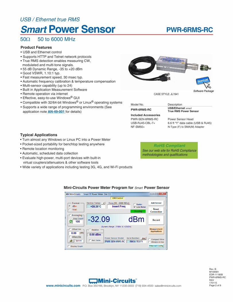
Product Features• USB and Ethernet control• Supports HTTP and Telnet network protocols• True RMS detection enables measuring CW, modulated and multi-tone signals. • 55 dB Dynamic Range, -35 to +20 dBm• Good VSWR, 1.10:1 typ.• Fast measurement speed, 30 msec typ.• Automatic frequency calibration & temperature compensation• Multi-sensor capability (up to 24)• Built in Application Measurement Software• Remote operation via internet• Effective, easy-to-use Windows® GUI • Compatible with 32/64-bit Windows® or Linux® operating systems• Supports a wide range of programming environments (See
application note AN-49-001 for details)
Typical Applications• Turn almost any Windows or Linux PC into a Power Meter• Pocket-sized portability for benchtop testing anywhere• Remote location monitoring • Automatic, scheduled data collection• Evaluate high-power, multi-port devices with built-in virtual couplers/attenuators & other software tools• Wide variety of applications including testing 3G, 4G, and Wi-Fi products
USB / Ethernet true RMS
Mini-Circuits Power Meter Program for Smart Power Sensor
Model No. Description
PWR-6RMS-RC USB/Ethernet smartTrue RMS Power Sensor
Included AccessoriesPWR-SEN-6RMS-RC Power Sensor HeadUSB-RJ45-CBL-7+ 6.6 ft “Y” data cable (USB & RJ45) NF-SM50+ N-Type (F) to SMA(M) Adapter
PWR-6RMS-RC
RoHS CompliantSee our web site for RoHS Compliance methodologies and qualifications
CASE STYLE: JL1941Software Package
Page 3 of 9Mini-Circuits®
www.minicircuits.com P.O. Box 350166, Brooklyn, NY 11235-0003 (718) 934-4500 [email protected]
PWR-6RMS-RCUSB/Ethernet true RMS Smart Power Sensor
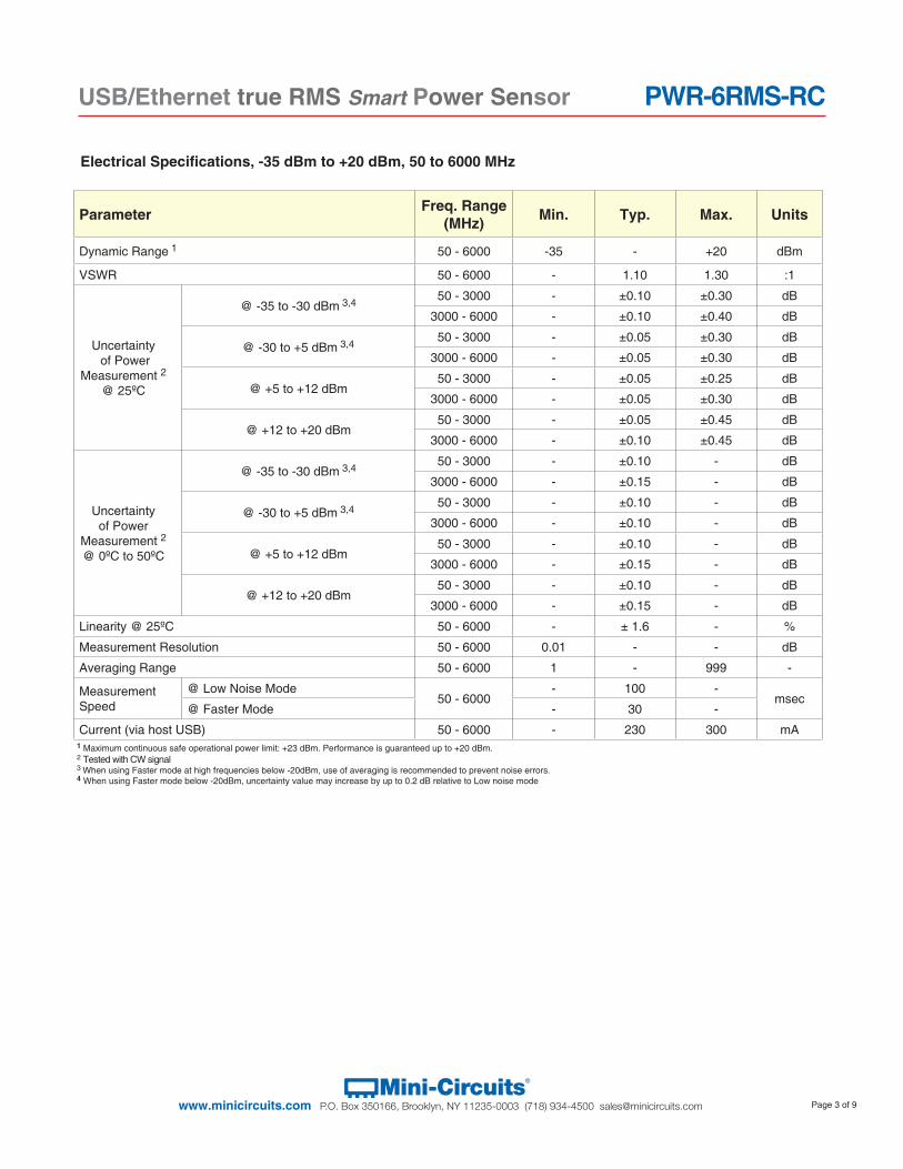
Parameter Freq. Range(MHz) Min. Typ. Max. Units
Dynamic Range 1 50 - 6000 -35 - +20 dBm
VSWR 50 - 6000 - 1.10 1.30 :1
Uncertainty of Power
Measurement 2
@ 25ºC
@ -35 to -30 dBm 3,4 50 - 3000 - ±0.10 ±0.30 dB
3000 - 6000 - ±0.10 ±0.40 dB
@ -30 to +5 dBm 3,4 50 - 3000 - ±0.05 ±0.30 dB
3000 - 6000 - ±0.05 ±0.30 dB
@ +5 to +12 dBm50 - 3000 - ±0.05 ±0.25 dB
3000 - 6000 - ±0.05 ±0.30 dB
@ +12 to +20 dBm50 - 3000 - ±0.05 ±0.45 dB
3000 - 6000 - ±0.10 ±0.45 dB
Uncertainty of Power
Measurement 2@ 0ºC to 50ºC
@ -35 to -30 dBm 3,4 50 - 3000 - ±0.10 - dB
3000 - 6000 - ±0.15 - dB
@ -30 to +5 dBm 3,4 50 - 3000 - ±0.10 - dB
3000 - 6000 - ±0.10 - dB
@ +5 to +12 dBm50 - 3000 - ±0.10 - dB
3000 - 6000 - ±0.15 - dB
@ +12 to +20 dBm50 - 3000 - ±0.10 - dB
3000 - 6000 - ±0.15 - dB
Linearity @ 25ºC 50 - 6000 - ± 1.6 - %
Measurement Resolution 50 - 6000 0.01 - - dB
Averaging Range 50 - 6000 1 - 999 -
Measurement Speed
@ Low Noise Mode50 - 6000
- 100 -msec
@ Faster Mode - 30 -
Current (via host USB) 50 - 6000 - 230 300 mA
Electrical Specifications, -35 dBm to +20 dBm, 50 to 6000 MHz
1 Maximum continuous safe operational power limit: +23 dBm. Performance is guaranteed up to +20 dBm.2 Tested with CW signal3 When using Faster mode at high frequencies below -20dBm, use of averaging is recommended to prevent noise errors. 4 When using Faster mode below -20dBm, uncertainty value may increase by up to 0.2 dB relative to Low noise mode
Page 4 of 9Mini-Circuits®
www.minicircuits.com P.O. Box 350166, Brooklyn, NY 11235-0003 (718) 934-4500 [email protected]
PWR-6RMS-RCUSB/Ethernet true RMS Smart Power Sensor
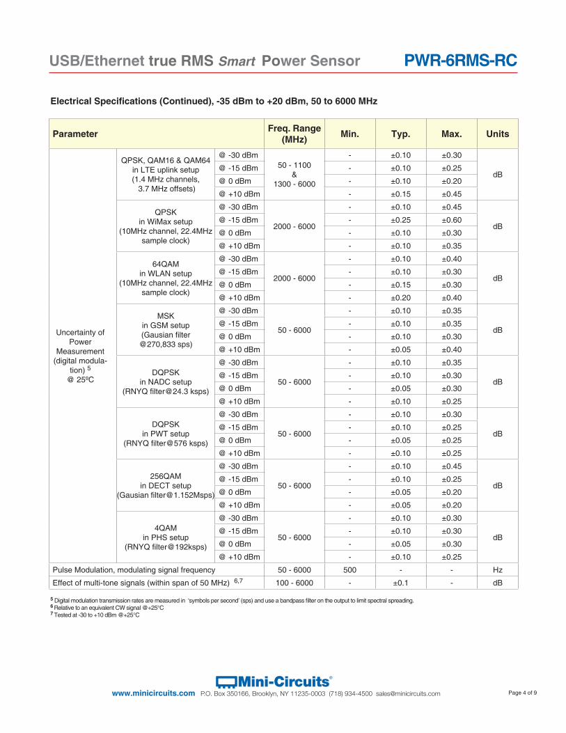
Parameter Freq. Range(MHz) Min. Typ. Max. Units
Uncertainty of Power
Measurement (digital modula-
tion) 5@ 25ºC
QPSK, QAM16 & QAM64 in LTE uplink setup(1.4 MHz channels, 3.7 MHz offsets)
@ -30 dBm50 - 1100
&1300 - 6000
- ±0.10 ±0.30
dB@ -15 dBm - ±0.10 ±0.25
@ 0 dBm - ±0.10 ±0.20
@ +10 dBm - ±0.15 ±0.45
QPSK in WiMax setup
(10MHz channel, 22.4MHz sample clock)
@ -30 dBm
2000 - 6000
- ±0.10 ±0.45
dB@ -15 dBm - ±0.25 ±0.60
@ 0 dBm - ±0.10 ±0.30
@ +10 dBm - ±0.10 ±0.35
64QAM in WLAN setup
(10MHz channel, 22.4MHz sample clock)
@ -30 dBm
2000 - 6000
- ±0.10 ±0.40
dB@ -15 dBm - ±0.10 ±0.30
@ 0 dBm - ±0.15 ±0.30
@ +10 dBm - ±0.20 ±0.40
MSK in GSM setup(Gausian filter
@270,833 sps)
@ -30 dBm
50 - 6000
- ±0.10 ±0.35
dB@ -15 dBm - ±0.10 ±0.35
@ 0 dBm - ±0.10 ±0.30
@ +10 dBm - ±0.05 ±0.40
DQPSK in NADC setup
(RNYQ [email protected] ksps)
@ -30 dBm
50 - 6000
- ±0.10 ±0.35
dB@ -15 dBm - ±0.10 ±0.30
@ 0 dBm - ±0.05 ±0.30
@ +10 dBm - ±0.10 ±0.25
DQPSK in PWT setup
(RNYQ filter@576 ksps)
@ -30 dBm
50 - 6000
- ±0.10 ±0.30
dB@ -15 dBm - ±0.10 ±0.25
@ 0 dBm - ±0.05 ±0.25
@ +10 dBm - ±0.10 ±0.25
256QAM in DECT setup
(Gausian [email protected])
@ -30 dBm
50 - 6000
- ±0.10 ±0.45
dB@ -15 dBm - ±0.10 ±0.25
@ 0 dBm - ±0.05 ±0.20
@ +10 dBm - ±0.05 ±0.20
4QAM in PHS setup
(RNYQ filter@192ksps)
@ -30 dBm
50 - 6000
- ±0.10 ±0.30
dB@ -15 dBm - ±0.10 ±0.30
@ 0 dBm - ±0.05 ±0.30
@ +10 dBm - ±0.10 ±0.25
Pulse Modulation, modulating signal frequency 50 - 6000 500 - - Hz
Effect of multi-tone signals (within span of 50 MHz) 6,7 100 - 6000 - ±0.1 - dB
Electrical Specifications (Continued), -35 dBm to +20 dBm, 50 to 6000 MHz
5 Digital modulation transmission rates are measured in ‘symbols per second’ (sps) and use a bandpass filter on the output to limit spectral spreading.6 Relative to an equivalent CW signal @+25°C 7 Tested at -30 to +10 dBm @+25°C
Page 5 of 9Mini-Circuits®
www.minicircuits.com P.O. Box 350166, Brooklyn, NY 11235-0003 (718) 934-4500 [email protected]
PWR-6RMS-RCUSB/Ethernet true RMS Smart Power Sensor
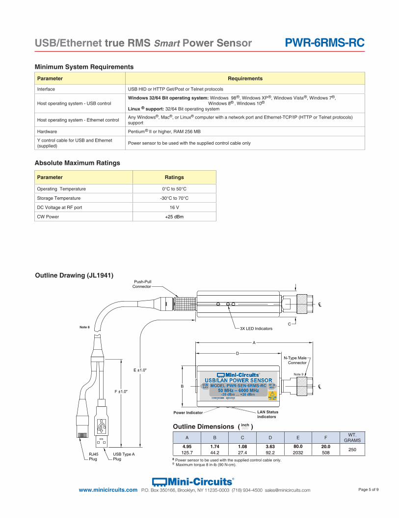
Absolute Maximum Ratings
Parameter Ratings
Operating Temperature 0°C to 50°C
Storage Temperature -30°C to 70°C
DC Voltage at RF port 16 V
CW Power +25 dBm
Minimum System Requirements
D
B
C
A
F ±1.0"
E ±1.0"
Push-PullConnector
RJ45Plug
N-Type MaleConnector
USB Type APlug
3X LED Indicators
Outline Drawing (JL1941)
A B C D E F WT. GRAMS
4.95 1.74 1.08 3.63 80.0 20.0250
125.7 44.2 27.4 92.2 2032 508
Outline Dimensions ( )inchmm
Note 8
8 Power sensor to be used with the supplied control cable only.9 Maximum torque 8 in-lb (90 N-cm).
Power Indicator LAN Status indicators
Parameter Requirements
Interface USB HID or HTTP Get/Post or Telnet protocols
Host operating system - USB controlWindows 32/64 Bit operating system: Windows 98
®, Windows XP ®, Windows Vista
®, Windows 7®, Windows 8® , Windows 10®
Linux ® support: 32/64 Bit operating system
Host operating system - Ethernet control Any Windows®, Mac®, or Linux® computer with a network port and Ethernet-TCP/IP (HTTP or Telnet protocols) support
Hardware Pentium ® II or higher, RAM 256 MB
Y control cable for USB and Ethernet (supplied) Power sensor to be used with the supplied control cable only
Note 9
Page 6 of 9Mini-Circuits®
www.minicircuits.com P.O. Box 350166, Brooklyn, NY 11235-0003 (718) 934-4500 [email protected]
PWR-6RMS-RCUSB/Ethernet true RMS Smart Power Sensor
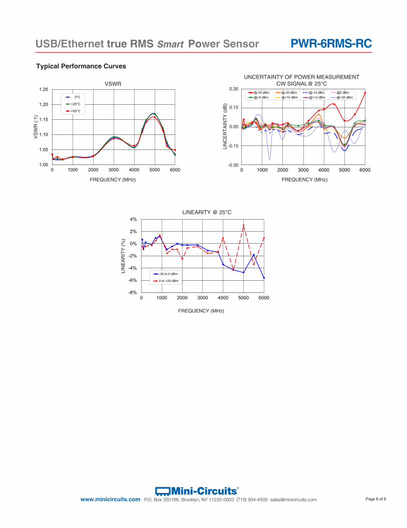
Typical Performance Curves
1.00
1.05
1.10
1.15
1.20
1.25
0 1000 2000 3000 4000 5000 6000
VSW
R (:
1)
FREQUENCY (MHz)
VSWR
0°C
+25°C
+50°C
VSWR
FREQUENCY (MHz)
VS
WR
(:1)
-8%
-6%
-4%
-2%
0%
2%
4%
0 1000 2000 3000 4000 5000 6000
Line
arity
(%)
Frequency (MHz)
LINEARITY @ 25OC
-35 to 0 dBm
0 to +20 dBm
FREQUENCY (MHz)
LIN
EA
RIT
Y (%
)
LINEARITY @ 25°C
-0.30
-0.15
0.00
0.15
0.30
0 1000 2000 3000 4000 5000 6000
UN
CER
TAIN
TY (d
B)
FREQUENCY (MHz)
UNCERTAINTY OF POWER MEASUREMENT@-35 dBm @-30 dBm @-12 dBm @0 dBm@+5 dBm @+10 dBm @+12 dBm @+20 dBm
@ 25OC
FREQUENCY (MHz)
UN
CE
RTA
INTY
(dB
)
0.30
0.15
0.00
-0.15
-0.30
UNCERTAINTY OF POWER MEASUREMENTCW SIGNAL@ 25°C
Page 7 of 9Mini-Circuits®
www.minicircuits.com P.O. Box 350166, Brooklyn, NY 11235-0003 (718) 934-4500 [email protected]
PWR-6RMS-RCUSB/Ethernet true RMS Smart Power Sensor
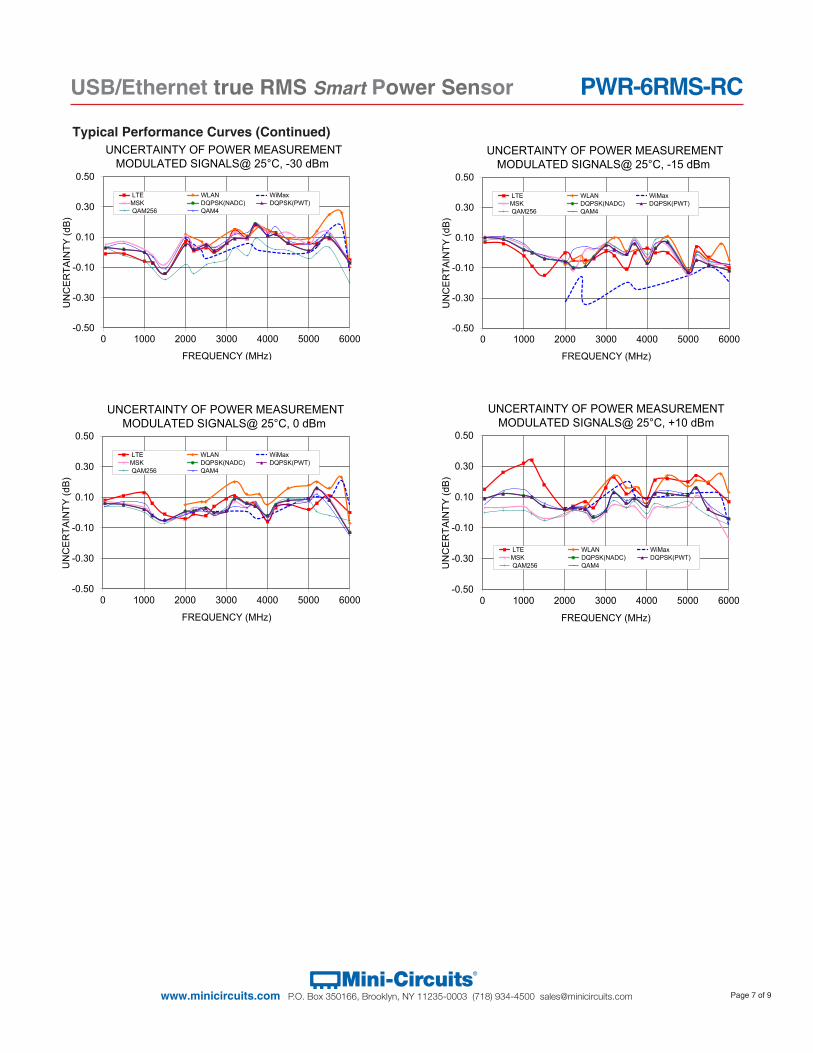
Typical Performance Curves (Continued)
-0.50
-0.30
-0.10
0.10
0.30
0.50
0 1000 2000 3000 4000 5000 6000
UN
CE
RTA
INTY
(dB
)
FREQUENCY (MHz)
UNCERTAINTY OF POWER MEASUREMENT
LTE WLAN WiMaxMSK DQPSK(NADC) DQPSK(PWT)QAM256 QAM4
MODULATED SIGNALS@ 25°C, -30 dBm
-0.50
-0.30
-0.10
0.10
0.30
0.50
0 1000 2000 3000 4000 5000 6000
UN
CE
RTA
INTY
(dB
)
FREQUENCY (MHz)
LTE WLAN WiMaxMSK DQPSK(NADC) DQPSK(PWT)QAM256 QAM4
UNCERTAINTY OF POWER MEASUREMENTMODULATED SIGNALS@ 25°C, -15 dBm
-0.50
-0.30
-0.10
0.10
0.30
0.50
0 1000 2000 3000 4000 5000 6000
UN
CE
RTA
INTY
(dB
)
FREQUENCY (MHz)
LTE WLAN WiMaxMSK DQPSK(NADC) DQPSK(PWT)QAM256 QAM4
UNCERTAINTY OF POWER MEASUREMENTMODULATED SIGNALS@ 25°C, 0 dBm
-0.50
-0.30
-0.10
0.10
0.30
0.50
0 1000 2000 3000 4000 5000 6000
UN
CE
RTA
INTY
(dB
)
FREQUENCY (MHz)
LTE WLAN WiMaxMSK DQPSK(NADC) DQPSK(PWT)QAM256 QAM4
UNCERTAINTY OF POWER MEASUREMENTMODULATED SIGNALS@ 25°C, +10 dBm
Page 8 of 9Mini-Circuits®
www.minicircuits.com P.O. Box 350166, Brooklyn, NY 11235-0003 (718) 934-4500 [email protected]
PWR-6RMS-RCUSB/Ethernet true RMS Smart Power Sensor
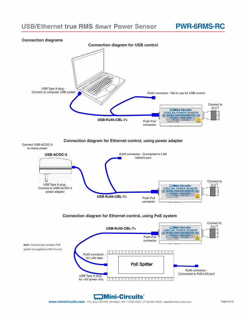
USB Type A plug -Connect to USB-AC/DC-5
power adaptor
RJ45 connector - Connected to LAN network port
USB-RJ45-CBL-7+
Connect to D.U.T
Push-Pull connector
USB-AC/DC-5
Connect USB-AC/DC-5 to mains power
Connection diagramsConnection diagram for USB control
Connection diagram for Ethernet control, using power adapter
Connection diagram for Ethernet control, using PoE system
USB-RJ45-CBL-7+
Connect to D.U.T
Push-Pull connector
RJ45 connector - Not in use for USB control
USB Type A plug -Connect to computer USB socket
RJ45 connector - for LAN data
USB-RJ45-CBL-7+
Connect to D.U.T
Push-Pull connector
PoE Splitter
USB Type A plug -for +5V power only
RJ45 connector - Connected to PoE/LAN port
Note: Commercially available PoE
splitter not supplied by Mini-Circuits
Page 9 of 9Mini-Circuits®
www.minicircuits.com P.O. Box 350166, Brooklyn, NY 11235-0003 (718) 934-4500 [email protected]
PWR-6RMS-RCUSB/Ethernet true RMS Smart Power Sensor
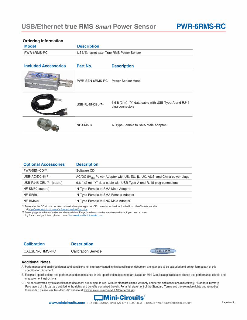
Included Accessories Part No. Description
PWR-SEN-6RMS-RC Power Sensor Head
USB-RJ45-CBL-7+ 6.6 ft (2 m) “Y” data cable with USB Type-A and RJ45 plug connectors
NF-SM50+ N-Type Female to SMA Male Adapter.
Model DescriptionPWR-6RMS-RC USB/Ethernet Smart True RMS Power Sensor
Ordering Information
Additional NotesA. Performance and quality attributes and conditions not expressly stated in this specification document are intended to be excluded and do not form a part of this
specification document. B. Electrical specifications and performance data contained in this specification document are based on Mini-Circuit’s applicable established test performance criteria and
measurement instructions. C. The parts covered by this specification document are subject to Mini-Circuits standard limited warranty and terms and conditions (collectively, “Standard Terms”);
Purchasers of this part are entitled to the rights and benefits contained therein. For a full statement of the Standard Terms and the exclusive rights and remedies thereunder, please visit Mini-Circuits’ website at www.minicircuits.com/MCLStore/terms.jsp
Calibration Description
CALSEN-6RMS-RC Calibration Service Click Here
Optional Accessories DescriptionPWR-SEN-CD10 Software CD
USB-AC/DC-5+11 AC/DC 5VDC Power Adapter with US, EU, IL, UK, AUS, and China power plugs
USB-RJ45-CBL-7+ (spare) 6.6 ft (2 m) “Y” data cable with USB Type-A and RJ45 plug connectors
NF-SM50+(spare) N-Type Female to SMA Male Adapter.
NF-SF50+ N-Type Female to SMA Female Adapter
NF-BM50+ N-Type Female to BNC Male Adapter.
11 Power plugs for other countries are also available, Plugs for other countries are also available, if you need a power plug for a countrynot listed please contact [email protected].
10 To receive the CD at no extra cost, request when placing order. CD contents can be downloaded from Mini-Circuits website at http://www.minicircuits.com/softwaredownload/pm.html


![(md09-i-s82) Per star RMS Outlier histogram 1200 4•10 ... · (md09-i-s82) Per star RMS 0 10 20 30 40 50 per star sigma-clipped RMS [mmag] 0 200 400 600 800 1000 1200 number Median](https://static.fdocument.org/doc/165x107/5e0edcb7d114187d3546de0e/md09-i-s82-per-star-rms-outlier-histogram-1200-4a10-md09-i-s82-per-star.jpg)

![Ethernet - Amirkabir University of Technologybme2.aut.ac.ir/~towhidkhah/MPC/seminars-ppt/seminar... · Ethernet was developed at Xerox PARC between 1973 and 1974.[1][2] It was inspired](https://static.fdocument.org/doc/165x107/5e8574eb8427ad2de61103b7/ethernet-amirkabir-university-of-towhidkhahmpcseminars-pptseminar-ethernet.jpg)