No Slide Titleengr · · 2007-09-19SEVENTH EDITION Electronic ... S = 10 Ω V S = 1.5 V A circuit...
28
Copyright © The McGraw-Hill Companies, Inc. Permission required for reproduction or display. MALVINO & BATES SEVENTH EDITION Electronic PRINCIPLES
Transcript of No Slide Titleengr · · 2007-09-19SEVENTH EDITION Electronic ... S = 10 Ω V S = 1.5 V A circuit...
Copyright © The McGraw-Hill Companies, Inc. Permission required for reproduction or display.
MALVINO & BATES
SEVENTH EDITION
ElectronicPRINCIPLES

Copyright © The McGraw-Hill Companies, Inc. Permission required for reproduction or display.
Diode TheoryDiode Theory
ChapterChapter 33
Copyright © The McGraw-Hill Companies, Inc. Permission required for reproduction or display.
Topics Covered in Chapter 3
• Basic ideas• The ideal diode• The second approximation• The third approximation• Troubleshooting• Up-down circuit analysis
Copyright © The McGraw-Hill Companies, Inc. Permission required for reproduction or display.
Topics Covered in Chapter 3(Continued)
• Reading a data sheet• How to calculate bulk resistance• DC Resistance of a diode• Load lines• Surface-mount diodes
Copyright © The McGraw-Hill Companies, Inc. Permission required for reproduction or display.
Diode
• A nonlinear device• The graph of current vs. voltage is not a
straight line• The diode voltage must exceed the
barrier voltage to conduct
Copyright © The McGraw-Hill Companies, Inc. Permission required for reproduction or display.
R
VSp
n=
Anode
Cathode
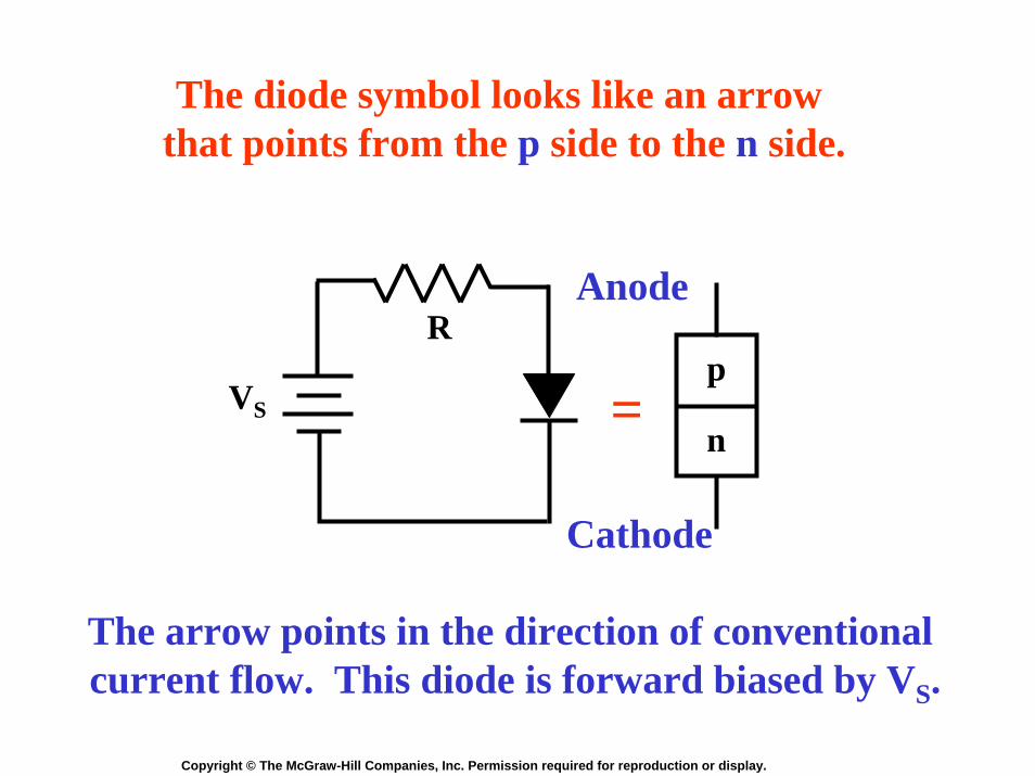
The diode symbol looks like an arrow that points from the p side to the n side.
The arrow points in the direction of conventional current flow. This diode is forward biased by VS.
Copyright © The McGraw-Hill Companies, Inc. Permission required for reproduction or display.
Linearity
• The volt-ampere characteristic curve for a resistor is a straight line (linear).
• A diode has a non-linear characteristic curve.
• The barrier potential produces a knee in the diode curve.
• The knee voltage is about 0.7 volts for a silicon diode.
Copyright © The McGraw-Hill Companies, Inc. Permission required for reproduction or display.
Forw
ard
curr
ent i
n m
A
0 0.5 1.0 1.50
25
50
75
100
125
150
175
200
Forward bias in volts
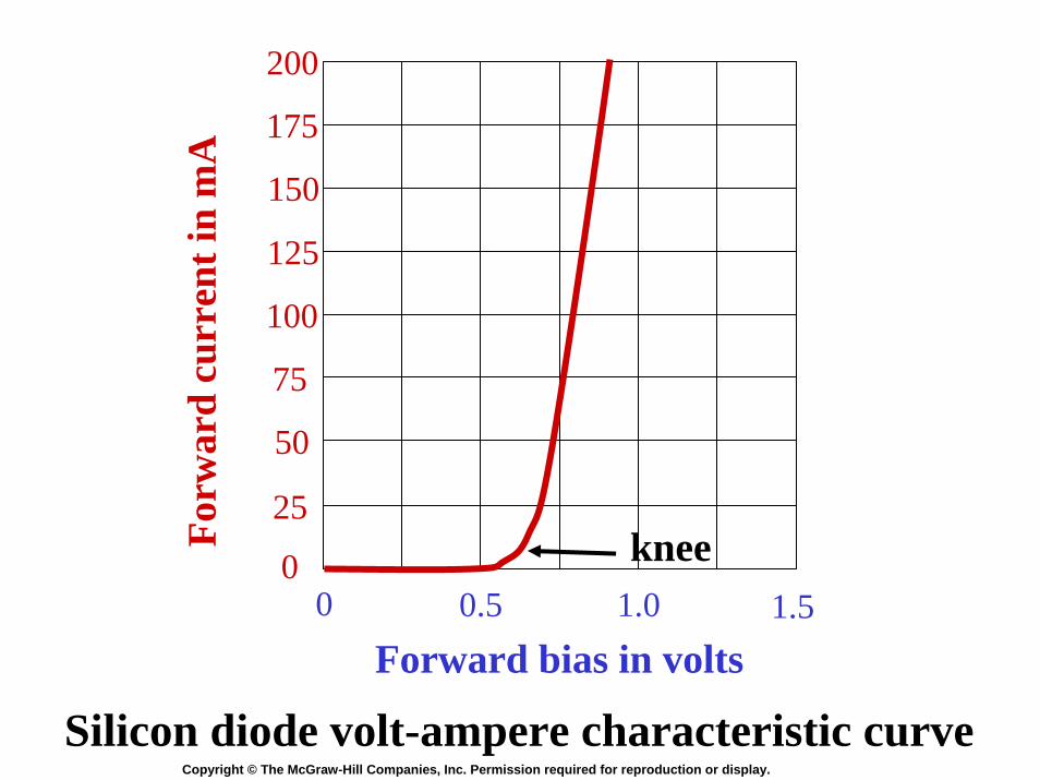
Silicon diode volt-ampere characteristic curve
knee

Copyright © The McGraw-Hill Companies, Inc. Permission required for reproduction or display.
0200400600
20
40
60
80
100
120
140
Reverse bias in Voltsbreakdown
Reversecurrentin mA
Silicon diode reverse bias characteristic curve
Copyright © The McGraw-Hill Companies, Inc. Permission required for reproduction or display.
Bulk resistance• The ohmic resistance of the p and n
material is called the bulk resistance.• The bulk resistance is often less than 1 Ω.• With forward bias, diode current
increases rapidly beyond the knee voltage.
• Small increases in voltage cause large increases in current.

Copyright © The McGraw-Hill Companies, Inc. Permission required for reproduction or display.
Diode ratings• Specified on manufacturers’ data sheets• The maximum reverse bias rating must
not be exceeded.• The maximum forward current rating
must not be exceeded.• The power rating of a diode is
determined by its maximum current rating and the forward voltage drop at that current flow.

Copyright © The McGraw-Hill Companies, Inc. Permission required for reproduction or display.
Diode first approximation
• This represents the diode as being ideal.• The first approximation ignores leakage
current, barrier potential and bulk resistance.
• When an ideal diode is forward biased, the model is a closed switch.
• When an ideal diode is reverse biased, the model is an open switch.

Copyright © The McGraw-Hill Companies, Inc. Permission required for reproduction or display.
First (ideal) approximation

Copyright © The McGraw-Hill Companies, Inc. Permission required for reproduction or display.
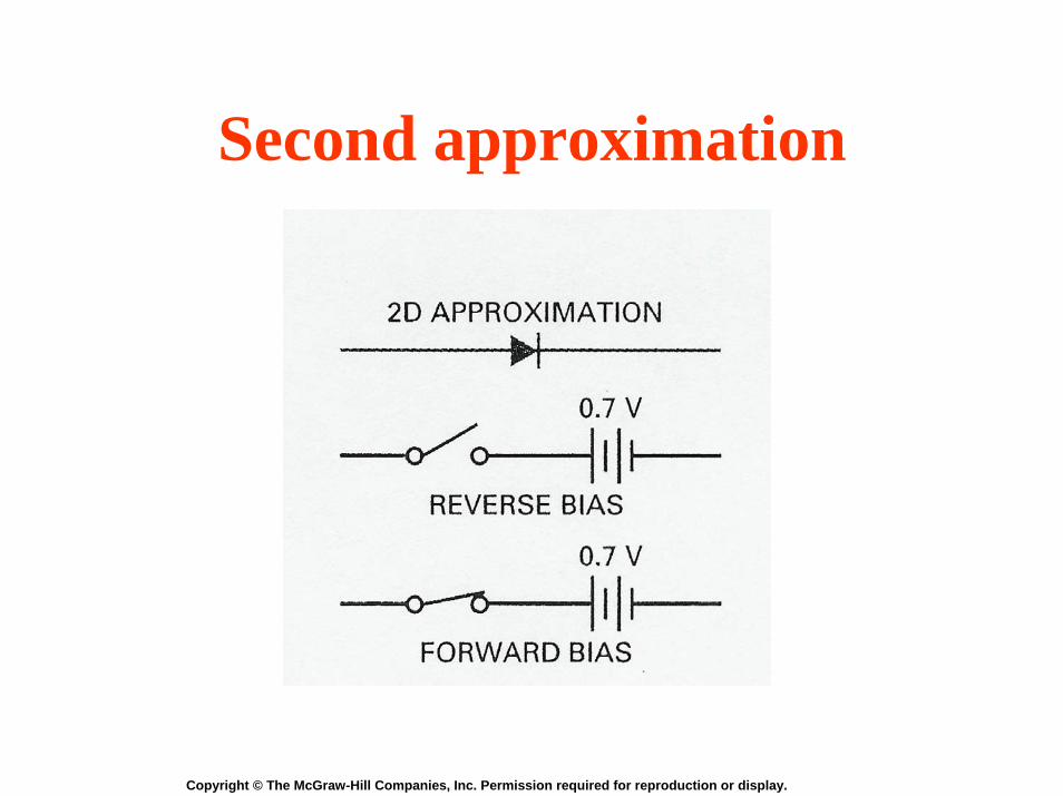
Diode second approximation
• This model assumes that no diode current flows until the forward bias across the diode reaches 0.7 volts.
• This model ignores the exact shape of the knee.
• This model ignores the diode’s bulk resistance.
Copyright © The McGraw-Hill Companies, Inc. Permission required for reproduction or display.
Second approximation
Copyright © The McGraw-Hill Companies, Inc. Permission required for reproduction or display.
• This model assumes that no diode current flows until the forward bias across the diode reaches 0.7 volts.
• This model ignores the exact shape of the knee.• This model does account for the diode’s bulk
resistance.However, bulk resistance that is less than 1 Ω can be ignored.
Diode third approximation

Copyright © The McGraw-Hill Companies, Inc. Permission required for reproduction or display.
Third approximation
RB0.7 V
Reverse bias
RB0.7 V
Forward bias

Copyright © The McGraw-Hill Companies, Inc. Permission required for reproduction or display.
Appropriate approximation• The first approximation is adequate for
most troubleshooting situations.• The second approximation is often used if
more accurate values for load current and voltage are required.
• The third approximation improvesaccuracy when the diode’s bulk resistance is more than 1/100 of the Thevenin resistance facing the diode.
Copyright © The McGraw-Hill Companies, Inc. Permission required for reproduction or display.
Silicon diode testing using an ohmmeter
• Low resistance in both directions: the diode is shorted.
• High resistance in both directions: the diode is open.
• Relatively low resistance in the reverse direction: the diode is leaky.
• If the ratio of reverse to forward resistance is > 1000: the diode is good.

Copyright © The McGraw-Hill Companies, Inc. Permission required for reproduction or display.
Silicon diode testing using a DMM
• Set DMM to diode test function• A connected forward-biased diode will
display the pn-junction’s forward voltage (~0.5V to 0.7V)
• When the diode is reversed-biased by the test leads, meter displays over-rangeindication such as “OL” or “1”

Copyright © The McGraw-Hill Companies, Inc. Permission required for reproduction or display.
Silicon diode testing using a DMM(continued)
• A shorted diode displays a voltage less than 0.5V in both directions
• An open diode would be indicated by an over-range display in both directions
• A leaky diode would display a voltage less than 2.0V in both directions

Copyright © The McGraw-Hill Companies, Inc. Permission required for reproduction or display.
Data sheets
• Useful to circuit designers• Useful to repair technicians• Typical entries include:
Breakdown voltageMaximum forward currentForward voltage drop
Copyright © The McGraw-Hill Companies, Inc. Permission required for reproduction or display.
Forw
ard
curr
ent i
n m
A
0 0.5 1.0 1.50
25
50
75
100
125
150
175
200
Forward bias in volts
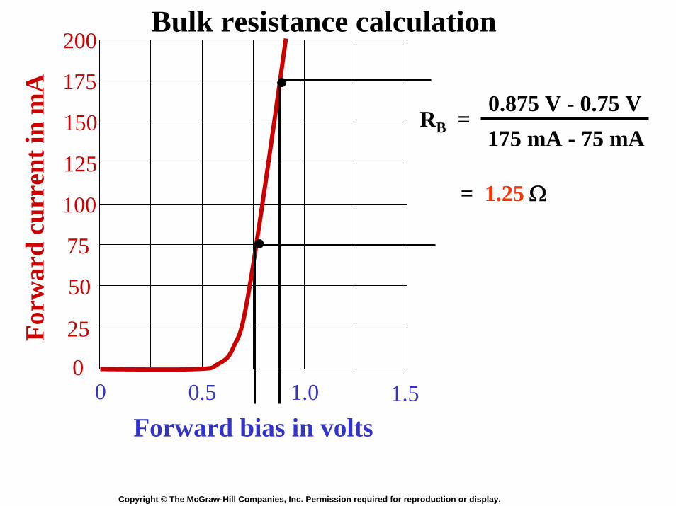
Bulk resistance calculation
175 mA - 75 mA0.875 V - 0.75 V
= 1.25 Ω
RB =
.
.

Copyright © The McGraw-Hill Companies, Inc. Permission required for reproduction or display.
Forw
ard
curr
ent i
n m
A
0 0.5 1.0 1.50
25
50
75
100
125
150
175
200
Forward bias in volts
The forward resistance decreases as current increases.
75 mA0.75 V
= 10 Ω
RF =
175 mA0.875 V
= 5 Ω
RF =
DC resistance
.
.

Copyright © The McGraw-Hill Companies, Inc. Permission required for reproduction or display.
Silicon diode resistance values
• The reverse resistance is very high: typically tens or hundreds of megohms.
• The forward resistance is not the same as the bulk resistance.
• The forward resistance is always greaterthan the bulk resistance.
• The forward resistance is equal to the bulk resistance plus the effect of the barrier potential.
Copyright © The McGraw-Hill Companies, Inc. Permission required for reproduction or display.
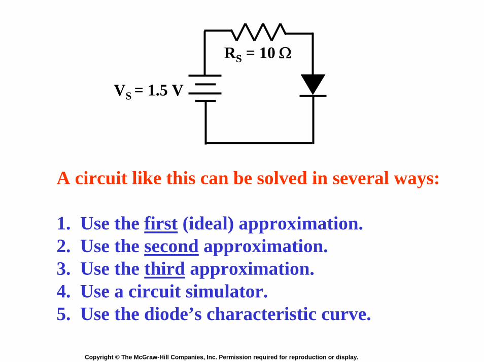
RS = 10 Ω
VS = 1.5 V
A circuit like this can be solved in several ways:
1. Use the first (ideal) approximation.2. Use the second approximation.3. Use the third approximation.4. Use a circuit simulator.5. Use the diode’s characteristic curve.
Copyright © The McGraw-Hill Companies, Inc. Permission required for reproduction or display.
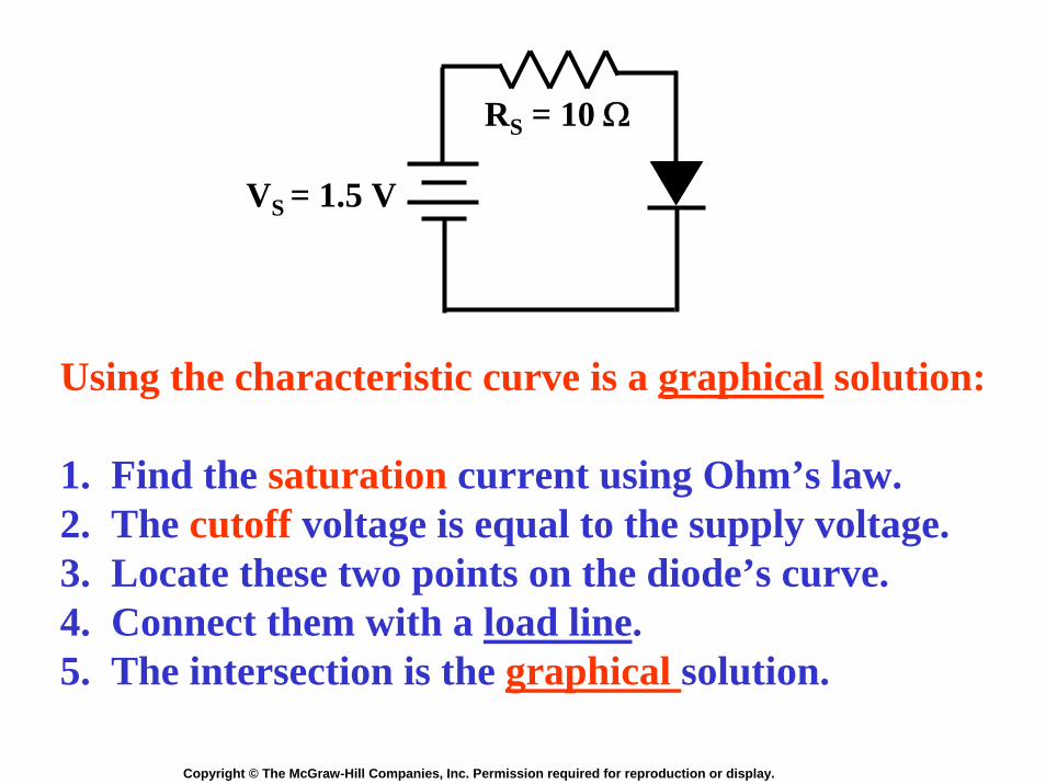
RS = 10 Ω
VS = 1.5 V
Using the characteristic curve is a graphical solution:
1. Find the saturation current using Ohm’s law.2. The cutoff voltage is equal to the supply voltage.3. Locate these two points on the diode’s curve.4. Connect them with a load line.5. The intersection is the graphical solution.
Copyright © The McGraw-Hill Companies, Inc. Permission required for reproduction or display.
Forw
ard
curr
ent i
n m
A
0 0.5 1.0 1.50
25
50
75
100
125
150
175
200
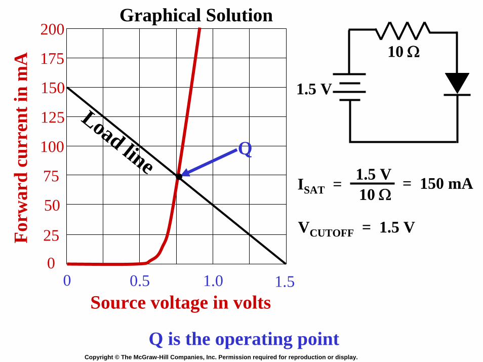
Source voltage in volts
ISAT =
10 Ω
1.5 V
1.5 V10 Ω
= 150 mA
VCUTOFF = 1.5 V
Q
Load line .
Graphical Solution
Q is the operating point


![No Slide Title · 2017-01-24 · • [3] Forrest Mims, Getting Started in Electronics, 1983 . 57 . Title: No Slide Title Author: Chuck Schuler Created Date: 12/20/2013 2:28:12 PM](https://static.fdocument.org/doc/165x107/5ec5871852e4935eab58019c/no-slide-2017-01-24-a-3-forrest-mims-getting-started-in-electronics-1983.jpg)