M series catalog - lemo-china.com · > 1012 Ω, > 1010 Ω (after humidity) IEC 60512-2 test 3a...
44
M SERIES CONNECTORS RATCHET COUPLING
Transcript of M series catalog - lemo-china.com · > 1012 Ω, > 1010 Ω (after humidity) IEC 60512-2 test 3a...
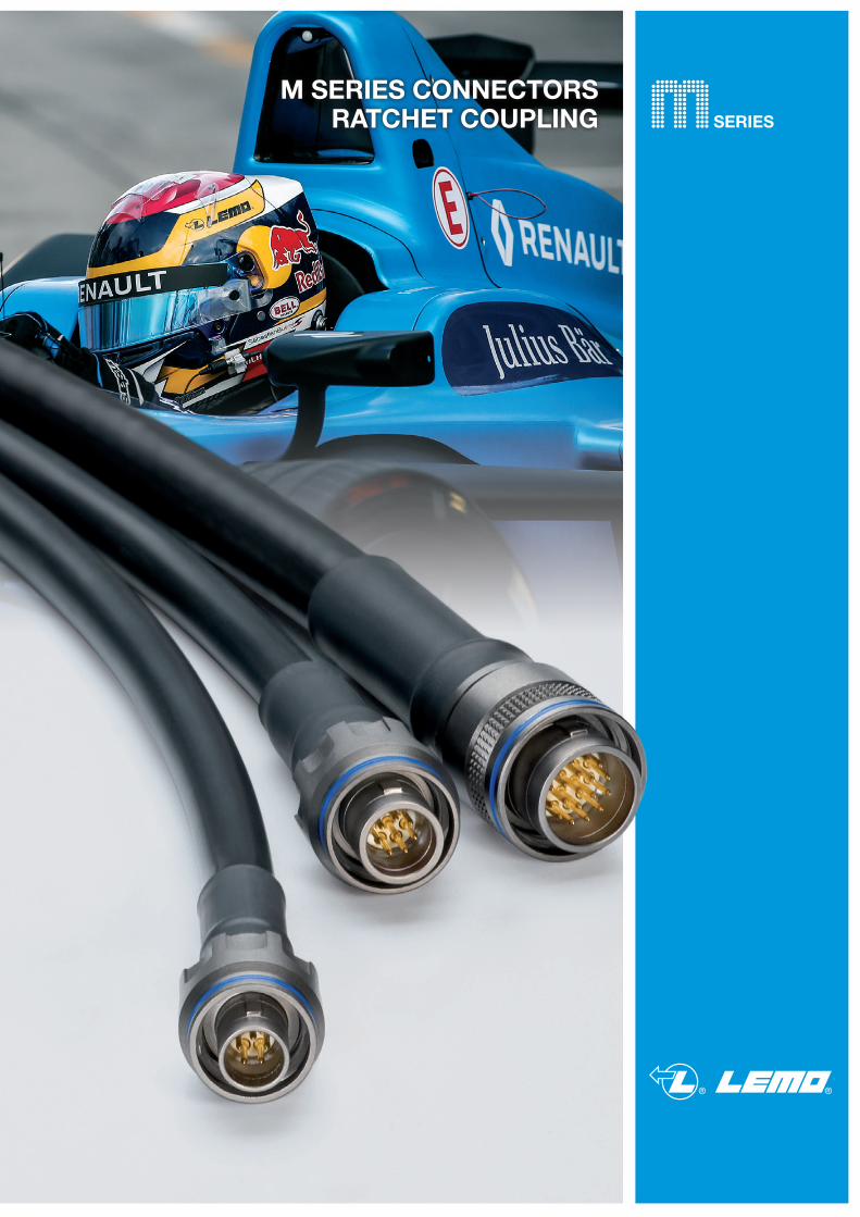
M SERIES CONNECTORSRATCHET COUPLING
® ®
www.lemo.com 1
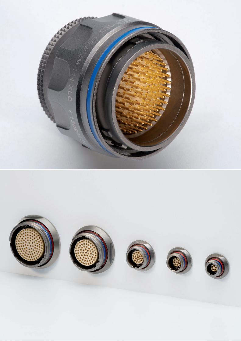
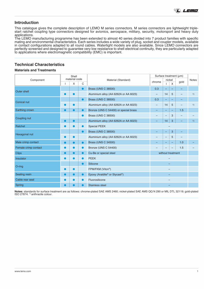
IntroductionThis catalogue gives the complete description of LEMO M series connectors. M series connectors are lightweight triple-start ratchet coupling type connectors designed for avionics, aerospace, military, security, motorsport and heavy duty applications. The LEMO manufacturing programme has been extended to almost 40 series divided into 7 product families with specific mating and environmental characteristics. Each series includes a wide variety of plug, socket and coupler models, available in contact configurations adapted to all round cables. Watertight models are also available. Since LEMO connectors are perfectly screened and designed to guarantee very low resistance to shell electrical continuity, they are particularly adapted to applications where electromagnetic compatibility (EMC) is important.
Component Material (Standard) Notes
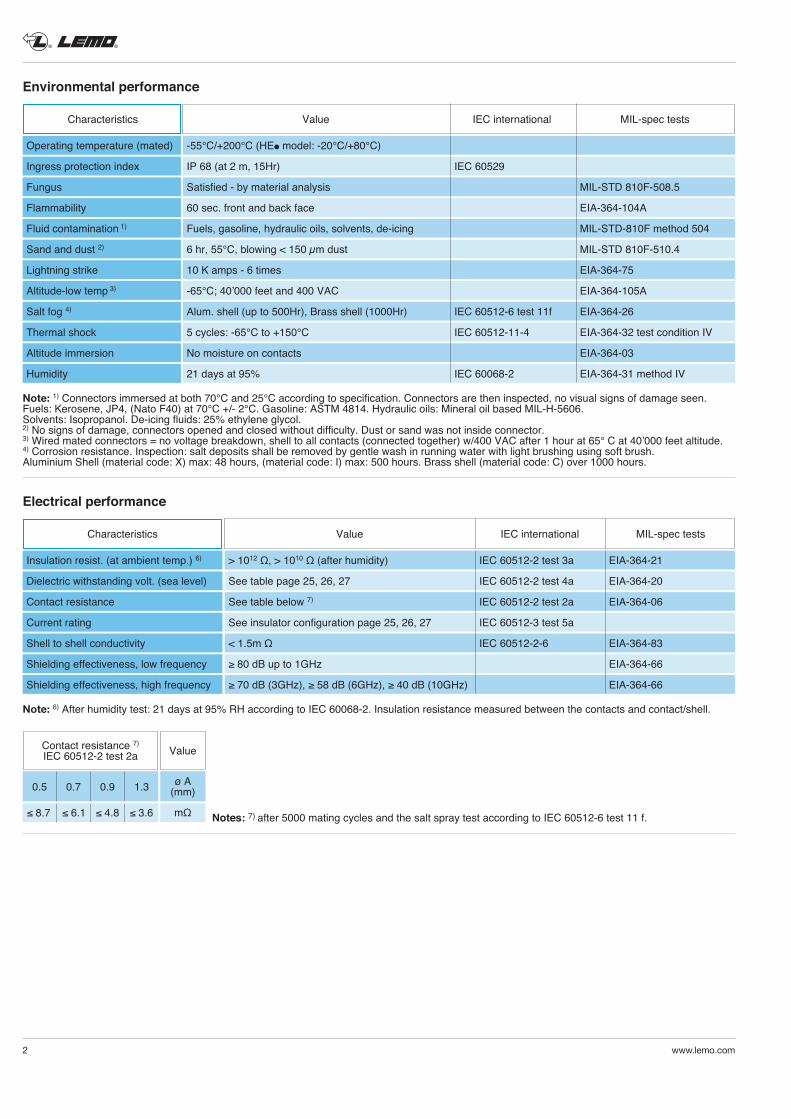
Notes: standards for surface treatment are as follows: chrome-plated SAE AMS 2460; nickel-plated SAE AMS QQ N 290 or MIL DTL 32119; gold-plated ISO 27874. 1) anthracite colour.
Technical CharacteristicsMaterials and Treatments
Shellmaterial code
I X C chrome gold
Surface treatment (µm) nickel I X
Outer shell
Conical nut
Earthing crown
Coupling nut
Ratchet
Hexagonal nut
Male crimp contact
Female crimp contact
Clips
Insulator
O-ring
Sealing resin
Cable rear seal
Spring
Brass (UNS C 38500)
Aluminium alloy (AA 6262A or AA 6023)
Brass (UNS C 38500)
Aluminium alloy (AA 6262A or AA 6023)
Bronze (UNS C 54400) or special brass
Brass (UNS C 38500)
Aluminium alloy (AA 6262A or AA 6023)
Special PEEK
Brass (UNS C 38500)
Aluminium alloy (AA 6262A or AA 6023)
Brass (UNS C 34500)
Bronze (UNS C 54400)
Cu-Be or special steel
PEEK
Silicone
FPM/FKM (Viton®)
Epoxy (Araldite® or Stycast®)
Fluorosilicone
Stainless steel
0.3 – – –
– 14 5 – 1)
0.3 – – –
– 14 5 – 1)
– – – 1.5
– – 3 – –
– 14 3 – 1)
–
– – 3 –
– – 5 –
– – – 1.0 –
– – – 1.5 –
without treatment
–
–
–
–
–
–
l
l l
l
l l
l l l
l
l l
l l l
l
l l
l l l
l l l
l l l
l l l
l
l l
l l l
l l l
l l l
® ®
2 www.lemo.com
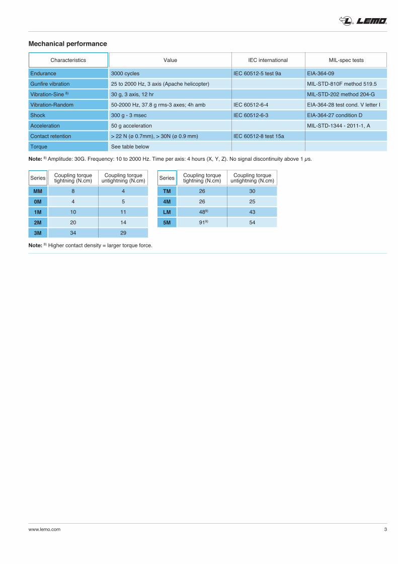
Environmental performance
Note: 1) Connectors immersed at both 70°C and 25°C according to specification. Connectors are then inspected, no visual signs of damage seen.Fuels: Kerosene, JP4, (Nato F40) at 70°C +/- 2°C. Gasoline: ASTM 4814. Hydraulic oils: Mineral oil based MIL-H-5606.Solvents: Isopropanol. De-icing fluids: 25% ethylene glycol.2) No signs of damage, connectors opened and closed without difficulty. Dust or sand was not inside connector. 3) Wired mated connectors = no voltage breakdown, shell to all contacts (connected together) w/400 VAC after 1 hour at 65° C at 40’000 feet altitude.4) Corrosion resistance. Inspection: salt deposits shall be removed by gentle wash in running water with light brushing using soft brush. Aluminium Shell (material code: X) max: 48 hours, (material code: I) max: 500 hours. Brass shell (material code: C) over 1000 hours.
Characteristics Value IEC international MIL-spec tests
Operating temperature (mated)
Ingress protection index
Fungus
Flammability
Fluid contamination 1)
Sand and dust 2)
Lightning strike
Altitude-low temp 3)
Salt fog 4)
Thermal shock
Altitude immersion
Humidity
-55°C/+200°C (HEl model: -20°C/+80°C)
IP 68 (at 2 m, 15Hr) IEC 60529
Satisfied - by material analysis MIL-STD 810F-508.5
60 sec. front and back face EIA-364-104A
Fuels, gasoline, hydraulic oils, solvents, de-icing MIL-STD-810F method 504
6 hr, 55°C, blowing < 150 µm dust MIL-STD 810F-510.4
10 K amps - 6 times EIA-364-75
-65°C; 40’000 feet and 400 VAC EIA-364-105A
Alum. shell (up to 500Hr), Brass shell (1000Hr) IEC 60512-6 test 11f EIA-364-26
5 cycles: -65°C to +150°C IEC 60512-11-4 EIA-364-32 test condition IV
No moisture on contacts EIA-364-03
21 days at 95% IEC 60068-2 EIA-364-31 method IV
Electrical performance
Characteristics Value IEC international MIL-spec tests
Insulation resist. (at ambient temp.) 6)
Dielectric withstanding volt. (sea level)
Contact resistance
Current rating
Shell to shell conductivity
Shielding effectiveness, low frequency
Shielding effectiveness, high frequency
> 1012 Ω, > 1010 Ω (after humidity) IEC 60512-2 test 3a EIA-364-21
See table page 25, 26, 27 IEC 60512-2 test 4a EIA-364-20
See table below 7) IEC 60512-2 test 2a EIA-364-06
See insulator configuration page 25, 26, 27 IEC 60512-3 test 5a
< 1.5m Ω IEC 60512-2-6 EIA-364-83
≥ 80 dB up to 1GHz EIA-364-66
≥ 70 dB (3GHz), ≥ 58 dB (6GHz), ≥ 40 dB (10GHz) EIA-364-66
Note: 6) After humidity test: 21 days at 95% RH according to IEC 60068-2. Insulation resistance measured between the contacts and contact/shell.
Notes: 7) after 5000 mating cycles and the salt spray test according to IEC 60512-6 test 11 f.
Contact resistance 7)
IEC 60512-2 test 2a Value
0.5 0.7 0.9 1.3
≤ 8.7 ≤ 6.1 ≤ 4.8 ≤ 3.6
ø A(mm)
mΩ
® ®
www.lemo.com 3
Note: 9) Higher contact density = larger torque force.
Mechanical performance
Note: 8) Amplitude: 30G. Frequency: 10 to 2000 Hz. Time per axis: 4 hours (X, Y, Z). No signal discontinuity above 1 µs.
Series Coupling torquetightning (N.cm)
Coupling torqueuntightning (N.cm)
MM
0M
1M
2M
3M
8 4
4 5
10 11
20 14
34 29
Series
TM
4M
LM
5M
Coupling torquetightning (N.cm)
Coupling torqueuntightning (N.cm)
26 30
26 25
489) 43
919) 54
Characteristics Value IEC international MIL-spec tests
Endurance
Gunfire vibration
Vibration-Sine 8)
Vibration-Random
Shock
Acceleration
Contact retention
Torque
3000 cycles IEC 60512-5 test 9a EIA-364-09
25 to 2000 Hz, 3 axis (Apache helicopter) MIL-STD-810F method 519.5
30 g, 3 axis, 12 hr MIL-STD-202 method 204-G
50-2000 Hz, 37.8 g rms-3 axes; 4h amb IEC 60512-6-4 EIA-364-28 test cond. V letter I
300 g - 3 msec IEC 60512-6-3 EIA-364-27 condition D
50 g acceleration MIL-STD-1344 - 2011-1, A
> 22 N (ø 0.7mm), > 30N (ø 0.9 mm) IEC 60512-8 test 15a
See table below
® ®
4 www.lemo.com
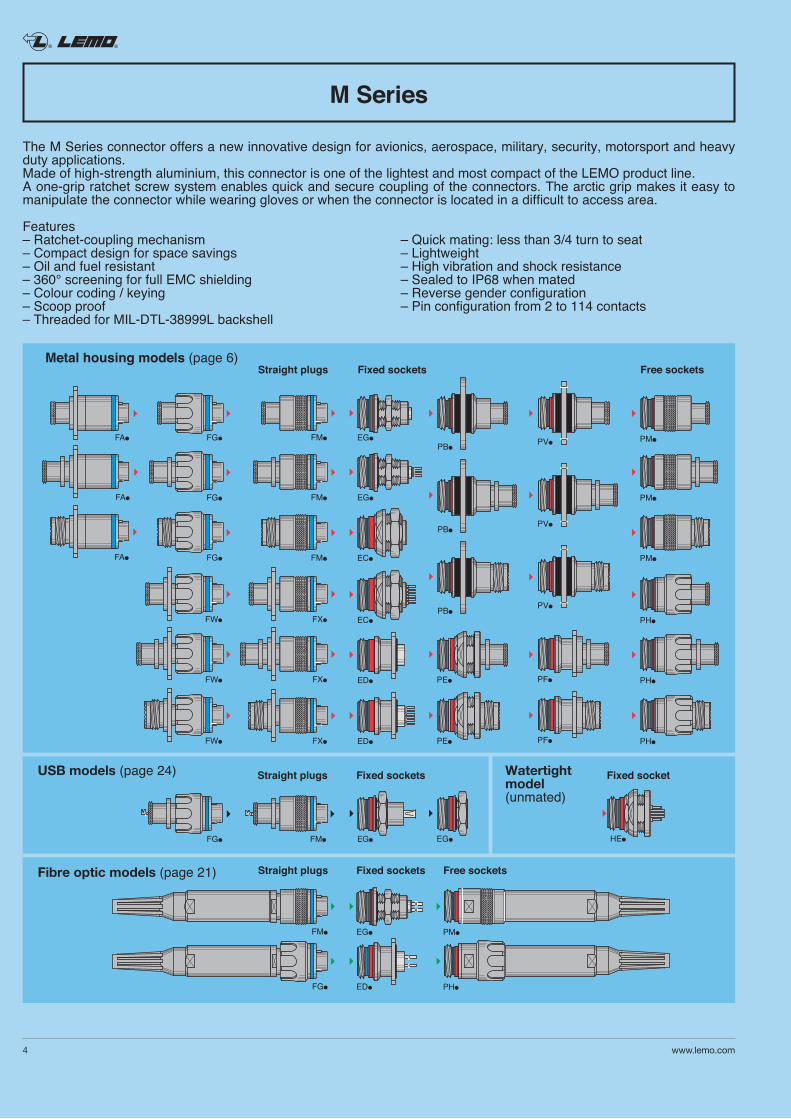
The M Series connector offers a new innovative design for avionics, aerospace, military, security, motorsport and heavy duty applications. Made of high-strength aluminium, this connector is one of the lightest and most compact of the LEMO product line.A one-grip ratchet screw system enables quick and secure coupling of the connectors. The arctic grip makes it easy to manipulate the connector while wearing gloves or when the connector is located in a difficult to access area.
Features– Ratchet-coupling mechanism – Quick mating: less than 3/4 turn to seat– Compact design for space savings – Lightweight– Oil and fuel resistant – High vibration and shock resistance– 360° screening for full EMC shielding – Sealed to IP68 when mated– Colour coding / keying – Reverse gender configuration– Scoop proof – Pin configuration from 2 to 114 contacts– Threaded for MIL-DTL-38999L backshell
M Series
Fixed socketsStraight plugs
EG
Free sockets
PM
PM
PM
PM
PH
PH
EG
PH
FG
FG
FG
FA
FA
FA
FM
FM
Fixed sockets Fixed socketStraight plugs
FM
FM
FW
FW
FW
FX
FX
FX
FM
Fixed sockets Free socketsStraight plugs
PB
PB
PBPV
PV
PV
PF
PF
EC
EC
ED
ED
HE
PE
PE
EG
FG EGEG
PHFG ED
Metal housing models (page 6)
Watertightmodel(unmated)
USB models (page 24)
Fibre optic models (page 21)
® ®
www.lemo.com 5
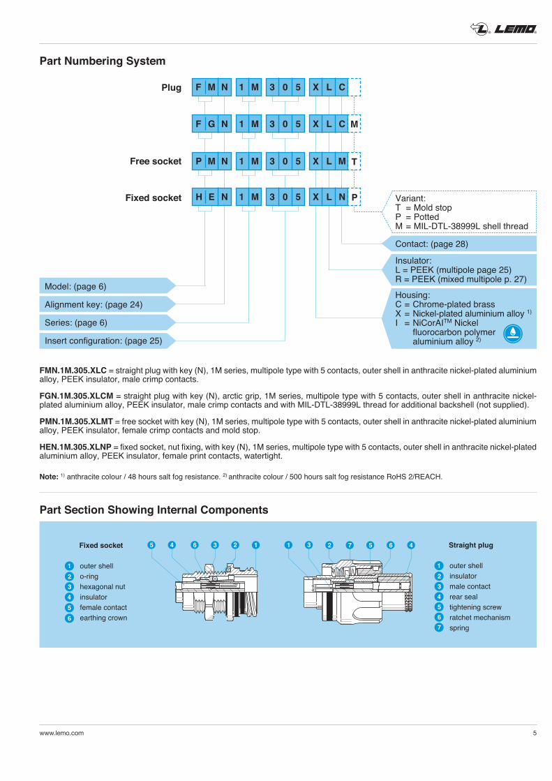
outer shello-ringhexagonal nutinsulatorfemale contactearthing crown
456
1
32
outer shellinsulatormale contactrear sealtightening screwratchet mechanismspring
1
32
4567
Fixed socket Straight plug2 134 65 231 7 5 6 4
Fixed socket
Part Numbering System
Plug
Free socket
FMN.1M.305.XLC = straight plug with key (N), 1M series, multipole type with 5 contacts, outer shell in anthracite nickel-plated aluminium alloy, PEEK insulator, male crimp contacts.
FGN.1M.305.XLCM = straight plug with key (N), arctic grip, 1M series, multipole type with 5 contacts, outer shell in anthracite nickel- plated aluminium alloy, PEEK insulator, male crimp contacts and with MIL-DTL-38999L thread for additional backshell (not supplied).
PMN.1M.305.XLMT = free socket with key (N), 1M series, multipole type with 5 contacts, outer shell in anthracite nickel-plated aluminium alloy, PEEK insulator, female crimp contacts and mold stop.
HEN.1M.305.XLNP = fixed socket, nut fixing, with key (N), 1M series, multipole type with 5 contacts, outer shell in anthracite nickel-plated aluminium alloy, PEEK insulator, female print contacts, watertight.
Note: 1) anthracite colour / 48 hours salt fog resistance. 2) anthracite colour / 500 hours salt fog resistance RoHS 2/REACH.
Part Section Showing Internal Components
Model: (page 6)
Alignment key: (page 24)
Series: (page 6)
Insert configuration: (page 25)
F M N 1 M 3 0 5 X L C
F G N 1 M 3 0 5 X L C M
P M N 1 M 3 0 5 X L M T
H E N 1 M 3 0 5 X L N P Variant:T = Mold stopP = PottedM = MIL-DTL-38999L shell thread
Contact: (page 28)
Insulator:L = PEEK (multipole page 25)R = PEEK (mixed multipole p. 27)
Housing:C = Chrome-plated brassX = Nickel-plated aluminium alloy 1)
I = NiCorAITM Nickel fluorocarbon polymer aluminium alloy 2)
® ®
Part number example: FMN.1M.305.XLC
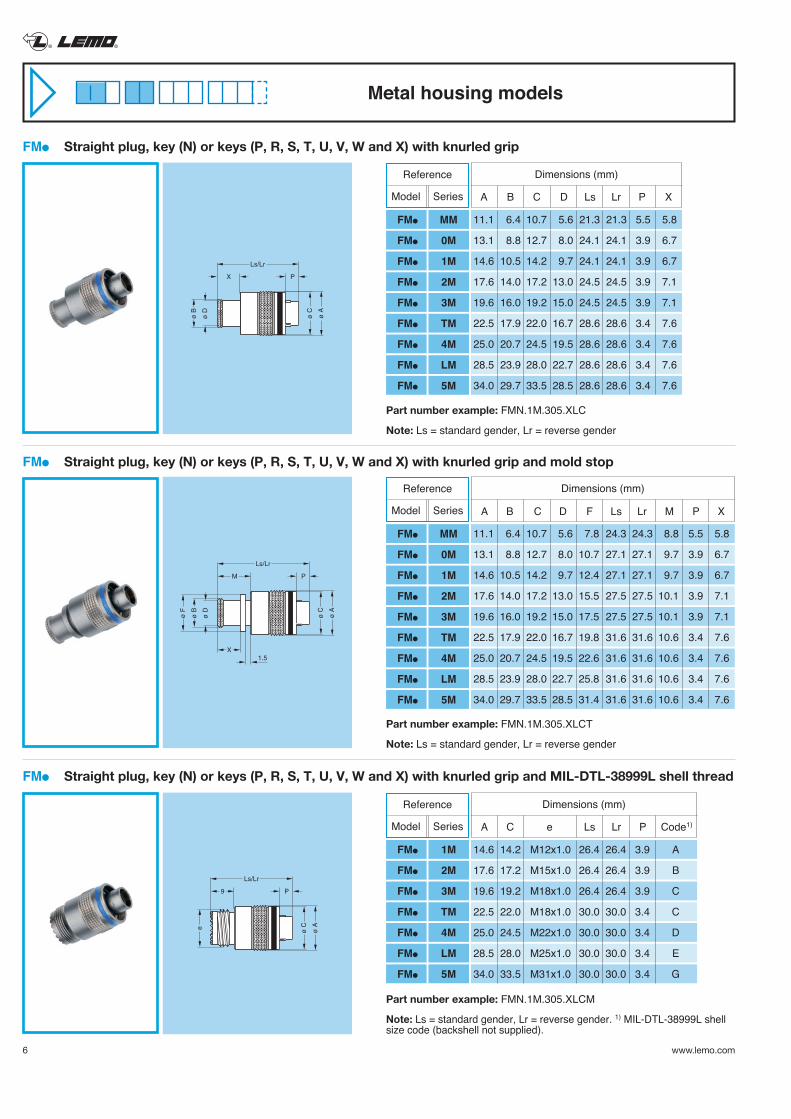
Note: Ls = standard gender, Lr = reverse gender
ø A
ø C
ø B
ø D
Ls/Lr
X P
ø A
ø C
ø B
ø F
ø D
Ls/Lr
M P
X1.5
FMl Straight plug, key (N) or keys (P, R, S, T, U, V, W and X) with knurled grip
11.1 6.4 10.7 5.6 21.3 21.3 5.5 5.8
13.1 8.8 12.7 8.0 24.1 24.1 3.9 6.7
14.6 10.5 14.2 9.7 24.1 24.1 3.9 6.7
17.6 14.0 17.2 13.0 24.5 24.5 3.9 7.1
19.6 16.0 19.2 15.0 24.5 24.5 3.9 7.1
22.5 17.9 22.0 16.7 28.6 28.6 3.4 7.6
25.0 20.7 24.5 19.5 28.6 28.6 3.4 7.6
28.5 23.9 28.0 22.7 28.6 28.6 3.4 7.6
34.0 29.7 33.5 28.5 28.6 28.6 3.4 7.6
A B C D Ls Lr P X
Dimensions (mm)
FMl Straight plug, key (N) or keys (P, R, S, T, U, V, W and X) with knurled grip and mold stop
ø A
ø Ce
Ls/Lr
9 P
FMl Straight plug, key (N) or keys (P, R, S, T, U, V, W and X) with knurled grip and MIL-DTL-38999L shell thread
Metal housing models
Reference
Model Series
FMl MM
FMl 0M
FMl 1M
FMl 2M
FMl 3M
FMl TM
FMl 4M
FMl LM
FMl 5M
11.1 6.4 10.7 5.6 7.8 24.3 24.3 8.8 5.5 5.8
13.1 8.8 12.7 8.0 10.7 27.1 27.1 9.7 3.9 6.7
14.6 10.5 14.2 9.7 12.4 27.1 27.1 9.7 3.9 6.7
17.6 14.0 17.2 13.0 15.5 27.5 27.5 10.1 3.9 7.1
19.6 16.0 19.2 15.0 17.5 27.5 27.5 10.1 3.9 7.1
22.5 17.9 22.0 16.7 19.8 31.6 31.6 10.6 3.4 7.6
25.0 20.7 24.5 19.5 22.6 31.6 31.6 10.6 3.4 7.6
28.5 23.9 28.0 22.7 25.8 31.6 31.6 10.6 3.4 7.6
34.0 29.7 33.5 28.5 31.4 31.6 31.6 10.6 3.4 7.6
A B C D F Ls Lr M P X
Dimensions (mm)
Part number example: FMN.1M.305.XLCT
Note: Ls = standard gender, Lr = reverse gender
Reference
Model Series
FMl MM
FMl 0M
FMl 1M
FMl 2M
FMl 3M
FMl TM
FMl 4M
FMl LM
FMl 5M
14.6 14.2 M12x1.0 26.4 26.4 3.9 A
17.6 17.2 M15x1.0 26.4 26.4 3.9 B
19.6 19.2 M18x1.0 26.4 26.4 3.9 C
22.5 22.0 M18x1.0 30.0 30.0 3.4 C
25.0 24.5 M22x1.0 30.0 30.0 3.4 D
28.5 28.0 M25x1.0 30.0 30.0 3.4 E
34.0 33.5 M31x1.0 30.0 30.0 3.4 G
A C e Ls Lr P Code1)
Dimensions (mm)
Part number example: FMN.1M.305.XLCM
Note: Ls = standard gender, Lr = reverse gender. 1) MIL-DTL-38999L shell size code (backshell not supplied).
Reference
Model Series
FMl 1M
FMl 2M
FMl 3M
FMl TM
FMl 4M
FMl LM
FMl 5M
6 www.lemo.com
® ®
www.lemo.com 7
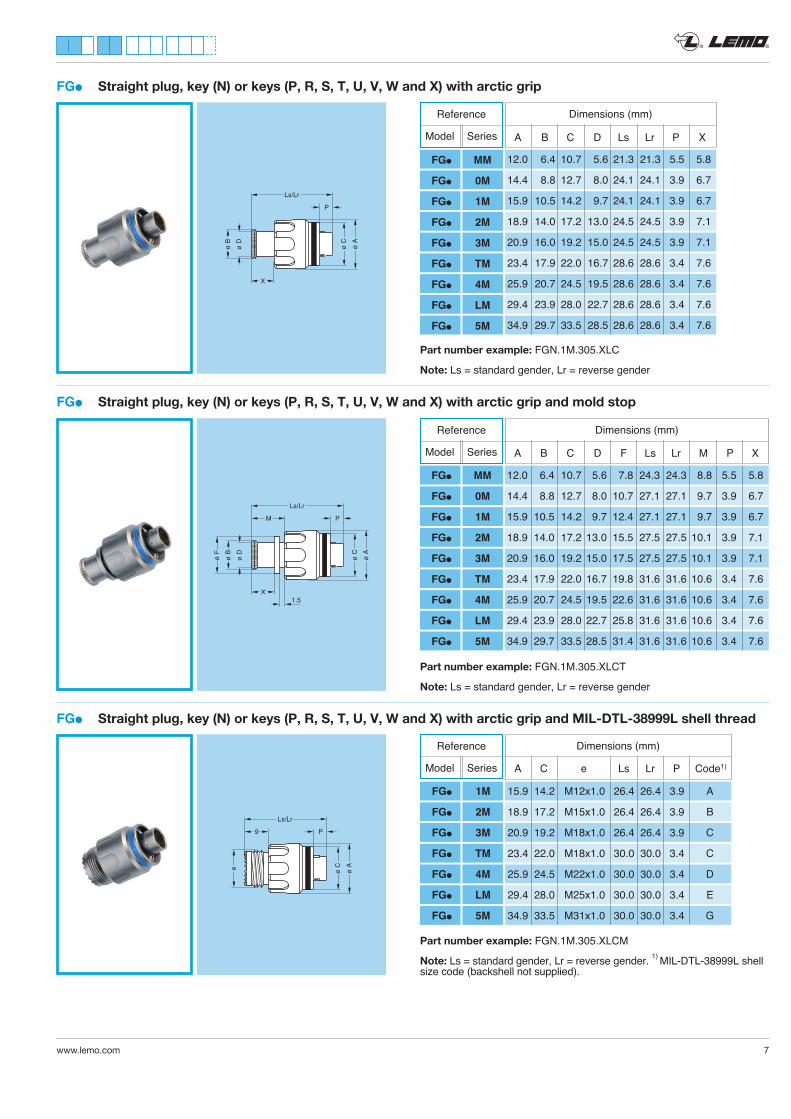
FGl Straight plug, key (N) or keys (P, R, S, T, U, V, W and X) with arctic grip
12.0 6.4 10.7 5.6 21.3 21.3 5.5 5.8
14.4 8.8 12.7 8.0 24.1 24.1 3.9 6.7
15.9 10.5 14.2 9.7 24.1 24.1 3.9 6.7
18.9 14.0 17.2 13.0 24.5 24.5 3.9 7.1
20.9 16.0 19.2 15.0 24.5 24.5 3.9 7.1
23.4 17.9 22.0 16.7 28.6 28.6 3.4 7.6
25.9 20.7 24.5 19.5 28.6 28.6 3.4 7.6
29.4 23.9 28.0 22.7 28.6 28.6 3.4 7.6
34.9 29.7 33.5 28.5 28.6 28.6 3.4 7.6
A B C D Ls Lr P X
Dimensions (mm)
ø A
ø C
ø B
ø D
Ls/Lr
P
X
Part number example: FGN.1M.305.XLC
Note: Ls = standard gender, Lr = reverse gender
FGl Straight plug, key (N) or keys (P, R, S, T, U, V, W and X) with arctic grip and mold stop
ø A
ø C
ø B
ø F
ø D
Ls/Lr
M P
X1.5
Part number example: FGN.1M.305.XLCT
Note: Ls = standard gender, Lr = reverse gender
FGl Straight plug, key (N) or keys (P, R, S, T, U, V, W and X) with arctic grip and MIL-DTL-38999L shell thread
e
9
ø A
ø C
Ls/Lr
P
15.9 14.2 M12x1.0 26.4 26.4 3.9 A
18.9 17.2 M15x1.0 26.4 26.4 3.9 B
20.9 19.2 M18x1.0 26.4 26.4 3.9 C
23.4 22.0 M18x1.0 30.0 30.0 3.4 C
25.9 24.5 M22x1.0 30.0 30.0 3.4 D
29.4 28.0 M25x1.0 30.0 30.0 3.4 E
34.9 33.5 M31x1.0 30.0 30.0 3.4 G
A C e Ls Lr P Code1)
Dimensions (mm)
Part number example: FGN.1M.305.XLCM
Note: Ls = standard gender, Lr = reverse gender. 1) MIL-DTL-38999L shell size code (backshell not supplied).
12.0 6.4 10.7 5.6 7.8 24.3 24.3 8.8 5.5 5.8
14.4 8.8 12.7 8.0 10.7 27.1 27.1 9.7 3.9 6.7
15.9 10.5 14.2 9.7 12.4 27.1 27.1 9.7 3.9 6.7
18.9 14.0 17.2 13.0 15.5 27.5 27.5 10.1 3.9 7.1
20.9 16.0 19.2 15.0 17.5 27.5 27.5 10.1 3.9 7.1
23.4 17.9 22.0 16.7 19.8 31.6 31.6 10.6 3.4 7.6
25.9 20.7 24.5 19.5 22.6 31.6 31.6 10.6 3.4 7.6
29.4 23.9 28.0 22.7 25.8 31.6 31.6 10.6 3.4 7.6
34.9 29.7 33.5 28.5 31.4 31.6 31.6 10.6 3.4 7.6
A B C D F Ls Lr M P X
Dimensions (mm)Reference
Model Series
FGl MM
FGl 0M
FGl 1M
FGl 2M
FGl 3M
FGl TM
FGl 4M
FGl LM
FGl 5M
Reference
Model Series
FGl 1M
FGl 2M
FGl 3M
FGl TM
FGl 4M
FGl LM
FGl 5M
Reference
Model Series
FGl MM
FGl 0M
FGl 1M
FGl 2M
FGl 3M
FGl TM
FGl 4M
FGl LM
FGl 5M
® ®
8 www.lemo.com
ø A
1
ø C
Ls/Lr
GK
X
P1.5
ø B
ø D
ø E
N
H ø V
ø A
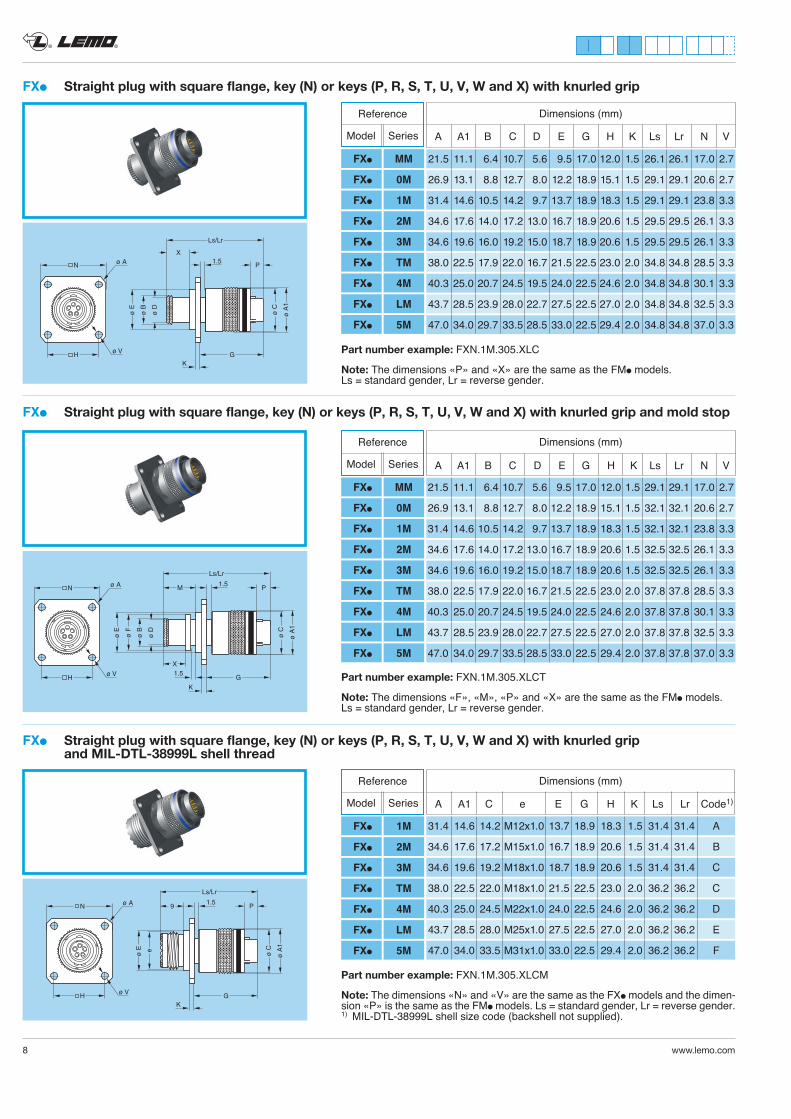
FXl Straight plug with square flange, key (N) or keys (P, R, S, T, U, V, W and X) with knurled grip
FXl Straight plug with square flange, key (N) or keys (P, R, S, T, U, V, W and X) with knurled grip and mold stop
ø A
1
ø C
Ls/Lr
G
K
P1.5
ø E
ø B
ø F
ø D
M
X1.5
N
H ø V
ø A
FXl Straight plug with square flange, key (N) or keys (P, R, S, T, U, V, W and X) with knurled grip and MIL-DTL-38999L shell thread
ø A
1
ø C
Ls/Lr
GK
P1.5
ø E e
9N
H ø V
ø A
Part number example: FXN.1M.305.XLCM
Note: The dimensions «N» and «V» are the same as the FXl models and the dimen-sion «P» is the same as the FMl models. Ls = standard gender, Lr = reverse gender. 1) MIL-DTL-38999L shell size code (backshell not supplied).
Part number example: FXN.1M.305.XLC
Note: The dimensions «P» and «X» are the same as the FMl models. Ls = standard gender, Lr = reverse gender.
Dimensions (mm)Reference
Model Series
FXl MM
FXl 0M
FXl 1M
FXl 2M
FXl 3M
FXl TM
FXl 4M
FXl LM
FXl 5M
A A1 B C D E G H K Ls Lr N V
21.5 11.1 6.4 10.7 5.6 9.5 17.0 12.0 1.5 26.1 26.1 17.0 2.7
26.9 13.1 8.8 12.7 8.0 12.2 18.9 15.1 1.5 29.1 29.1 20.6 2.7
31.4 14.6 10.5 14.2 9.7 13.7 18.9 18.3 1.5 29.1 29.1 23.8 3.3
34.6 17.6 14.0 17.2 13.0 16.7 18.9 20.6 1.5 29.5 29.5 26.1 3.3
34.6 19.6 16.0 19.2 15.0 18.7 18.9 20.6 1.5 29.5 29.5 26.1 3.3
38.0 22.5 17.9 22.0 16.7 21.5 22.5 23.0 2.0 34.8 34.8 28.5 3.3
40.3 25.0 20.7 24.5 19.5 24.0 22.5 24.6 2.0 34.8 34.8 30.1 3.3
43.7 28.5 23.9 28.0 22.7 27.5 22.5 27.0 2.0 34.8 34.8 32.5 3.3
47.0 34.0 29.7 33.5 28.5 33.0 22.5 29.4 2.0 34.8 34.8 37.0 3.3
Part number example: FXN.1M.305.XLCT
Note: The dimensions «F», «M», «P» and «X» are the same as the FMl models. Ls = standard gender, Lr = reverse gender.
Dimensions (mm)Reference
Model Series
FXl MM
FXl 0M
FXl 1M
FXl 2M
FXl 3M
FXl TM
FXl 4M
FXl LM
FXl 5M
A A1 B C D E G H K Ls Lr N V
21.5 11.1 6.4 10.7 5.6 9.5 17.0 12.0 1.5 29.1 29.1 17.0 2.7
26.9 13.1 8.8 12.7 8.0 12.2 18.9 15.1 1.5 32.1 32.1 20.6 2.7
31.4 14.6 10.5 14.2 9.7 13.7 18.9 18.3 1.5 32.1 32.1 23.8 3.3
34.6 17.6 14.0 17.2 13.0 16.7 18.9 20.6 1.5 32.5 32.5 26.1 3.3
34.6 19.6 16.0 19.2 15.0 18.7 18.9 20.6 1.5 32.5 32.5 26.1 3.3
38.0 22.5 17.9 22.0 16.7 21.5 22.5 23.0 2.0 37.8 37.8 28.5 3.3
40.3 25.0 20.7 24.5 19.5 24.0 22.5 24.6 2.0 37.8 37.8 30.1 3.3
43.7 28.5 23.9 28.0 22.7 27.5 22.5 27.0 2.0 37.8 37.8 32.5 3.3
47.0 34.0 29.7 33.5 28.5 33.0 22.5 29.4 2.0 37.8 37.8 37.0 3.3
31.4 14.6 14.2 M12x1.0 13.7 18.9 18.3 1.5 31.4 31.4 A
34.6 17.6 17.2 M15x1.0 16.7 18.9 20.6 1.5 31.4 31.4 B
34.6 19.6 19.2 M18x1.0 18.7 18.9 20.6 1.5 31.4 31.4 C
38.0 22.5 22.0 M18x1.0 21.5 22.5 23.0 2.0 36.2 36.2 C
40.3 25.0 24.5 M22x1.0 24.0 22.5 24.6 2.0 36.2 36.2 D
43.7 28.5 28.0 M25x1.0 27.5 22.5 27.0 2.0 36.2 36.2 E
47.0 34.0 33.5 M31x1.0 33.0 22.5 29.4 2.0 36.2 36.2 F
Dimensions (mm)Reference
Model Series
FXl 1M
FXl 2M
FXl 3M
FXl TM
FXl 4M
FXl LM
FXl 5M
A A1 C e E G H K Ls Lr Code1)
® ®
www.lemo.com 9
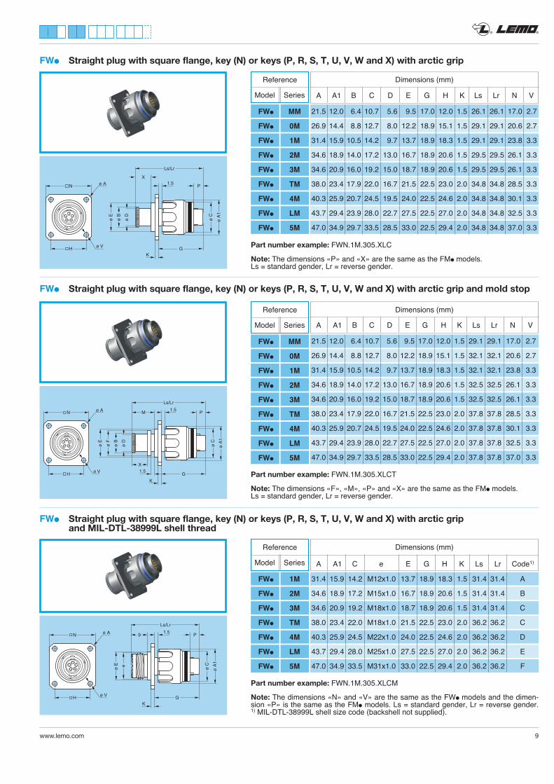
Part number example: FWN.1M.305.XLC
Note: The dimensions «P» and «X» are the same as the FMl models. Ls = standard gender, Lr = reverse gender.
Ls/Lr
GK
X1.5
ø B
ø D
ø E
ø A
1
ø C
PN
H ø V
ø A
FWl Straight plug with square flange, key (N) or keys (P, R, S, T, U, V, W and X) with arctic grip
Ls/Lr
G
K
1.5
ø E
ø B
ø F
ø D
M
X1.5
ø A
1
ø C
PN
H ø V
ø A
FWl Straight plug with square flange, key (N) or keys (P, R, S, T, U, V, W and X) with arctic grip and mold stop
Part number example: FWN.1M.305.XLCT
Note: The dimensions «F», «M», «P» and «X» are the same as the FMl models. Ls = standard gender, Lr = reverse gender.
FWl Straight plug with square flange, key (N) or keys (P, R, S, T, U, V, W and X) with arctic grip and MIL-DTL-38999L shell thread
Ls/Lr
GK
1.5
ø E e
9
ø A
1
ø C
PN
H ø V
ø A
Part number example: FWN.1M.305.XLCM
Note: The dimensions «N» and «V» are the same as the FWl models and the dimen-sion «P» is the same as the FMl models. Ls = standard gender, Lr = reverse gender. 1) MIL-DTL-38999L shell size code (backshell not supplied).
Dimensions (mm)
21.5 12.0 6.4 10.7 5.6 9.5 17.0 12.0 1.5 29.1 29.1 17.0 2.7
26.9 14.4 8.8 12.7 8.0 12.2 18.9 15.1 1.5 32.1 32.1 20.6 2.7
31.4 15.9 10.5 14.2 9.7 13.7 18.9 18.3 1.5 32.1 32.1 23.8 3.3
34.6 18.9 14.0 17.2 13.0 16.7 18.9 20.6 1.5 32.5 32.5 26.1 3.3
34.6 20.9 16.0 19.2 15.0 18.7 18.9 20.6 1.5 32.5 32.5 26.1 3.3
38.0 23.4 17.9 22.0 16.7 21.5 22.5 23.0 2.0 37.8 37.8 28.5 3.3
40.3 25.9 20.7 24.5 19.5 24.0 22.5 24.6 2.0 37.8 37.8 30.1 3.3
43.7 29.4 23.9 28.0 22.7 27.5 22.5 27.0 2.0 37.8 37.8 32.5 3.3
47.0 34.9 29.7 33.5 28.5 33.0 22.5 29.4 2.0 37.8 37.8 37.0 3.3
A A1 B C D E G H K Ls Lr N V
Reference
Model Series
FWl MM
FWl 0M
FWl 1M
FWl 2M
FWl 3M
FWl TM
FWl 4M
FWl LM
FWl 5M
A A1 B C D E G H K Ls Lr N V
Dimensions (mm)Reference
Model Series
FWl MM
FWl 0M
FWl 1M
FWl 2M
FWl 3M
FWl TM
FWl 4M
FWl LM
FWl 5M
21.5 12.0 6.4 10.7 5.6 9.5 17.0 12.0 1.5 26.1 26.1 17.0 2.7
26.9 14.4 8.8 12.7 8.0 12.2 18.9 15.1 1.5 29.1 29.1 20.6 2.7
31.4 15.9 10.5 14.2 9.7 13.7 18.9 18.3 1.5 29.1 29.1 23.8 3.3
34.6 18.9 14.0 17.2 13.0 16.7 18.9 20.6 1.5 29.5 29.5 26.1 3.3
34.6 20.9 16.0 19.2 15.0 18.7 18.9 20.6 1.5 29.5 29.5 26.1 3.3
38.0 23.4 17.9 22.0 16.7 21.5 22.5 23.0 2.0 34.8 34.8 28.5 3.3
40.3 25.9 20.7 24.5 19.5 24.0 22.5 24.6 2.0 34.8 34.8 30.1 3.3
43.7 29.4 23.9 28.0 22.7 27.5 22.5 27.0 2.0 34.8 34.8 32.5 3.3
47.0 34.9 29.7 33.5 28.5 33.0 22.5 29.4 2.0 34.8 34.8 37.0 3.3
31.4 15.9 14.2 M12x1.0 13.7 18.9 18.3 1.5 31.4 31.4 A
34.6 18.9 17.2 M15x1.0 16.7 18.9 20.6 1.5 31.4 31.4 B
34.6 20.9 19.2 M18x1.0 18.7 18.9 20.6 1.5 31.4 31.4 C
38.0 23.4 22.0 M18x1.0 21.5 22.5 23.0 2.0 36.2 36.2 C
40.3 25.9 24.5 M22x1.0 24.0 22.5 24.6 2.0 36.2 36.2 D
43.7 29.4 28.0 M25x1.0 27.5 22.5 27.0 2.0 36.2 36.2 E
47.0 34.9 33.5 M31x1.0 33.0 22.5 29.4 2.0 36.2 36.2 F
A A1 C e E G H K Ls Lr Code1)
Dimensions (mm)Reference
Model Series
FWl 1M
FWl 2M
FWl 3M
FWl TM
FWl 4M
FWl LM
FWl 5M
® ®
10 www.lemo.com
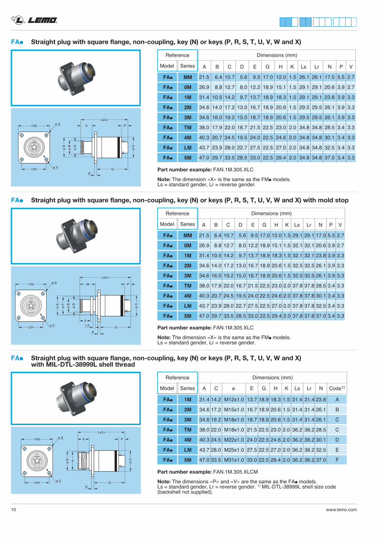
FAl Straight plug with square flange, non-coupling, key (N) or keys (P, R, S, T, U, V, W and X)
ø C
Ls/Lr
GK
X P
ø B
ø D
ø E
N
H ø V
ø A
21.5 6.4 10.7 5.6 9.5 17.0 12.0 1.5 26.1 26.1 17.0 5.5 2.7
26.9 8.8 12.7 8.0 12.2 18.9 15.1 1.5 29.1 29.1 20.6 3.9 2.7
31.4 10.5 14.2 9.7 13.7 18.9 18.3 1.5 29.1 29.1 23.8 3.9 3.3
34.6 14.0 17.2 13.0 16.7 18.9 20.6 1.5 29.5 29.5 26.1 3.9 3.3
34.6 16.0 19.2 15.0 18.7 18.9 20.6 1.5 29.5 29.5 26.1 3.9 3.3
38.0 17.9 22.0 16.7 21.5 22.5 23.0 2.0 34.8 34.8 28.5 3.4 3.3
40.3 20.7 24.5 19.5 24.0 22.5 24.6 2.0 34.8 34.8 30.1 3.4 3.3
43.7 23.9 28.0 22.7 27.5 22.5 27.0 2.0 34.8 34.8 32.5 3.4 3.3
47.0 29.7 33.5 28.5 33.0 22.5 29.4 2.0 34.8 34.8 37.0 3.4 3.3
A B C D E G H K Ls Lr N P V
Dimensions (mm)
Part number example: FAN.1M.305.XLC
Note: The dimension «X» is the same as the FMl models. Ls = standard gender, Lr = reverse gender.
FAl Straight plug with square flange, non-coupling, key (N) or keys (P, R, S, T, U, V, W and X) with mold stop
ø C
Ls/Lr
G
K
P
ø E
ø B
ø F
ø D
M
X1.5
N
H ø V
ø A
Part number example: FAN.1M.305.XLC
Note: The dimension «X» is the same as the FMl models. Ls = standard gender, Lr = reverse gender.
FAl Straight plug with square flange, non-coupling, key (N) or keys (P, R, S, T, U, V, W and X) with MIL-DTL-38999L shell thread
ø C
Ls/Lr
GK
P
ø E e
9N
H ø V
ø A
Part number example: FAN.1M.305.XLCM
Note: The dimensions «P» and «V» are the same as the FAl models. Ls = standard gender, Lr = reverse gender. 1) MIL-DTL-38999L shell size code (backshell not supplied).
Reference
Model Series
FAl MM
FAl 0M
FAl 1M
FAl 2M
FAl 3M
FAl TM
FAl 4M
FAl LM
FAl 5M
21.5 6.4 10.7 5.6 9.5 17.0 12.0 1.5 29.1 29.1 17.0 5.5 2.7
26.9 8.8 12.7 8.0 12.2 18.9 15.1 1.5 32.1 32.1 20.6 3.9 2.7
31.4 10.5 14.2 9.7 13.7 18.9 18.3 1.5 32.1 32.1 23.8 3.9 3.3
34.6 14.0 17.2 13.0 16.7 18.9 20.6 1.5 32.5 32.5 26.1 3.9 3.3
34.6 16.0 19.2 15.0 18.7 18.9 20.6 1.5 32.5 32.5 26.1 3.9 3.3
38.0 17.9 22.0 16.7 21.5 22.5 23.0 2.0 37.8 37.8 28.5 3.4 3.3
40.3 20.7 24.5 19.5 24.0 22.5 24.6 2.0 37.8 37.8 30.1 3.4 3.3
43.7 23.9 28.0 22.7 27.5 22.5 27.0 2.0 37.8 37.8 32.5 3.4 3.3
47.0 29.7 33.5 28.5 33.0 22.5 29.4 2.0 37.8 37.8 37.0 3.4 3.3
A B C D E G H K Ls Lr N P V
Dimensions (mm)Reference
Model Series
FAl MM
FAl 0M
FAl 1M
FAl 2M
FAl 3M
FAl TM
FAl 4M
FAl LM
FAl 5M
31.4 14.2 M12x1.0 13.7 18.9 18.3 1.5 31.4 31.4 23.8 A
34.6 17.2 M15x1.0 16.7 18.9 20.6 1.5 31.4 31.4 26.1 B
34.6 19.2 M18x1.0 18.7 18.9 20.6 1.5 31.4 31.4 26.1 C
38.0 22.0 M18x1.0 21.5 22.5 23.0 2.0 36.2 36.2 28.5 C
40.3 24.5 M22x1.0 24.0 22.5 24.6 2.0 36.2 36.2 30.1 D
43.7 28.0 M25x1.0 27.5 22.5 27.0 2.0 36.2 36.2 32.5 E
47.0 33.5 M31x1.0 33.0 22.5 29.4 2.0 36.2 36.2 37.0 F
A C e E G H K Ls Lr N Code1)
Dimensions (mm)Reference
Model Series
FAl 1M
FAl 2M
FAl 3M
FAl TM
FAl 4M
FAl LM
FAl 5M
® ®
www.lemo.com 11
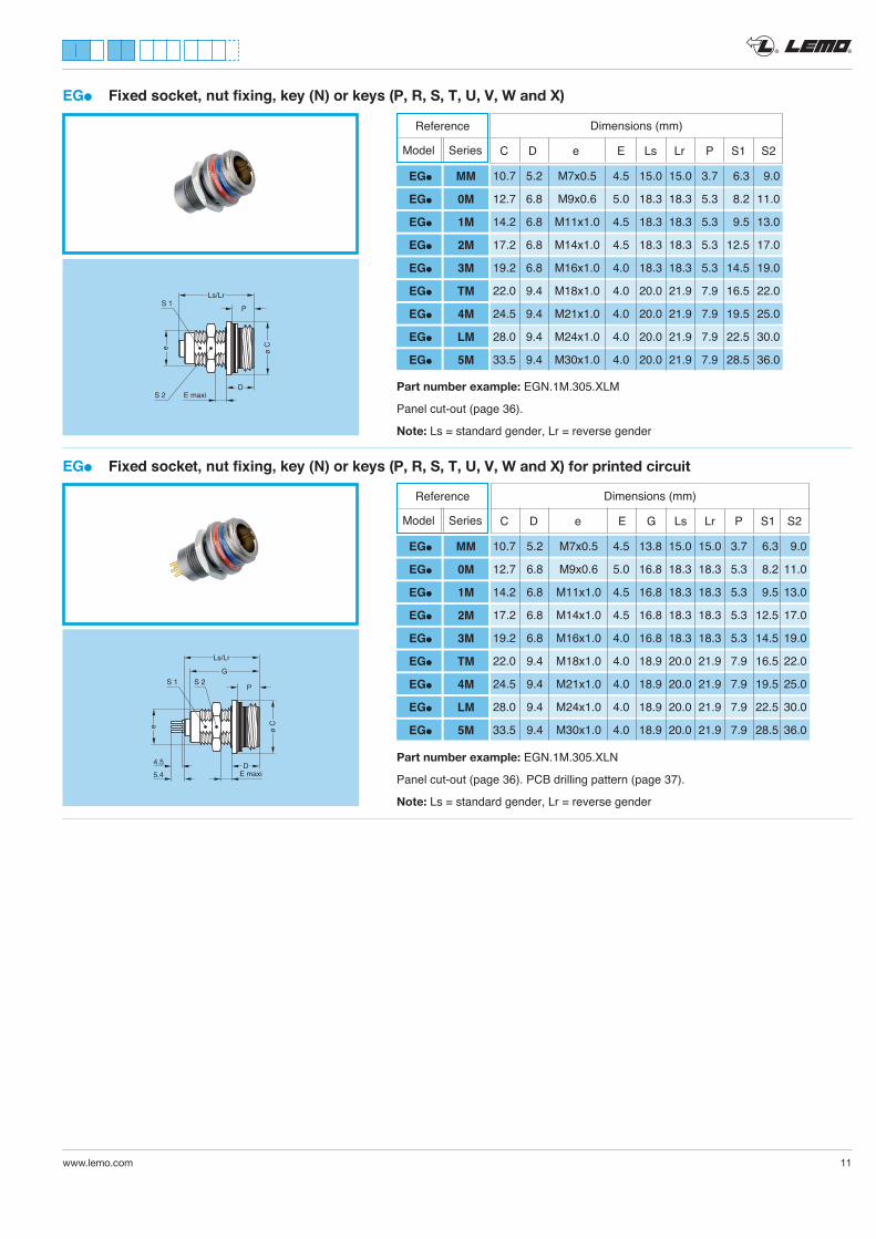
EGl Fixed socket, nut fixing, key (N) or keys (P, R, S, T, U, V, W and X)
Part number example: EGN.1M.305.XLM
Panel cut-out (page 36).
Note: Ls = standard gender, Lr = reverse gender
EGl Fixed socket, nut fixing, key (N) or keys (P, R, S, T, U, V, W and X) for printed circuit
Part number example: EGN.1M.305.XLN
Panel cut-out (page 36). PCB drilling pattern (page 37).
Note: Ls = standard gender, Lr = reverse gender
ø Ce
Ls/Lr
P
DE maxiS 2
S 1
ø Ce
Ls/Lr
G
P
DE maxi
S 1 S 2
4.5
5.4
Dimensions (mm)
10.7 5.2 M7x0.5 4.5 15.0 15.0 3.7 6.3 9.0
12.7 6.8 M9x0.6 5.0 18.3 18.3 5.3 8.2 11.0
14.2 6.8 M11x1.0 4.5 18.3 18.3 5.3 9.5 13.0
17.2 6.8 M14x1.0 4.5 18.3 18.3 5.3 12.5 17.0
19.2 6.8 M16x1.0 4.0 18.3 18.3 5.3 14.5 19.0
22.0 9.4 M18x1.0 4.0 20.0 21.9 7.9 16.5 22.0
24.5 9.4 M21x1.0 4.0 20.0 21.9 7.9 19.5 25.0
28.0 9.4 M24x1.0 4.0 20.0 21.9 7.9 22.5 30.0
33.5 9.4 M30x1.0 4.0 20.0 21.9 7.9 28.5 36.0
C D e E Ls Lr P S1 S2
Reference
Model Series
EGl MM
EGl 0M
EGl 1M
EGl 2M
EGl 3M
EGl TM
EGl 4M
EGl LM
EGl 5M
Dimensions (mm)
C D e E G Ls Lr P S1 S2
10.7 5.2 M7x0.5 4.5 13.8 15.0 15.0 3.7 6.3 9.0
12.7 6.8 M9x0.6 5.0 16.8 18.3 18.3 5.3 8.2 11.0
14.2 6.8 M11x1.0 4.5 16.8 18.3 18.3 5.3 9.5 13.0
17.2 6.8 M14x1.0 4.5 16.8 18.3 18.3 5.3 12.5 17.0
19.2 6.8 M16x1.0 4.0 16.8 18.3 18.3 5.3 14.5 19.0
22.0 9.4 M18x1.0 4.0 18.9 20.0 21.9 7.9 16.5 22.0
24.5 9.4 M21x1.0 4.0 18.9 20.0 21.9 7.9 19.5 25.0
28.0 9.4 M24x1.0 4.0 18.9 20.0 21.9 7.9 22.5 30.0
33.5 9.4 M30x1.0 4.0 18.9 20.0 21.9 7.9 28.5 36.0
Reference
Model Series
EGl MM
EGl 0M
EGl 1M
EGl 2M
EGl 3M
EGl TM
EGl 4M
EGl LM
EGl 5M
® ®
12 www.lemo.com
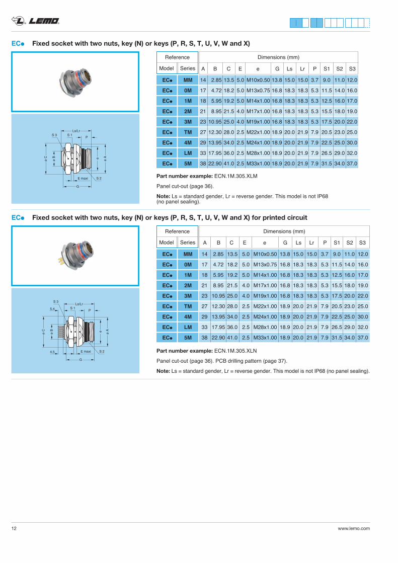
ECl Fixed socket with two nuts, key (N) or keys (P, R, S, T, U, V, W and X) for printed circuit
e ø A
ø C
ø B
Ls/Lr
P
E maxi
G
S 2
S 1
S 3
5.4
4.5 Part number example: ECN.1M.305.XLN
Panel cut-out (page 36). PCB drilling pattern (page 37).
Note: Ls = standard gender, Lr = reverse gender. This model is not IP68 (no panel sealing).
A B C E e G Ls Lr P S1 S2 S3
Dimensions (mm)
14 2.85 13.5 5.0 M10x0.50 13.8 15.0 15.0 3.7 9.0 11.0 12.0
17 4.72 18.2 5.0 M13x0.75 16.8 18.3 18.3 5.3 11.5 14.0 16.0
18 5.95 19.2 5.0 M14x1.00 16.8 18.3 18.3 5.3 12.5 16.0 17.0
21 8.95 21.5 4.0 M17x1.00 16.8 18.3 18.3 5.3 15.5 18.0 19.0
23 10.95 25.0 4.0 M19x1.00 16.8 18.3 18.3 5.3 17.5 20.0 22.0
27 12.30 28.0 2.5 M22x1.00 18.9 20.0 21.9 7.9 20.5 23.0 25.0
29 13.95 34.0 2.5 M24x1.00 18.9 20.0 21.9 7.9 22.5 25.0 30.0
33 17.95 36.0 2.5 M28x1.00 18.9 20.0 21.9 7.9 26.5 29.0 32.0
38 22.90 41.0 2.5 M33x1.00 18.9 20.0 21.9 7.9 31.5 34.0 37.0
Reference
Model Series
ECl MM
ECl 0M
ECl 1M
ECl 2M
ECl 3M
ECl TM
ECl 4M
ECl LM
ECl 5M
ECl Fixed socket with two nuts, key (N) or keys (P, R, S, T, U, V, W and X)
e ø A
ø C
ø B
Ls/Lr
P
E maxi
G
S 2
S 1S 3
Part number example: ECN.1M.305.XLM
Panel cut-out (page 36).
Note: Ls = standard gender, Lr = reverse gender. This model is not IP68 (no panel sealing).
A B C E e G Ls Lr P S1 S2 S3
Dimensions (mm)
14 2.85 13.5 5.0 M10x0.50 13.8 15.0 15.0 3.7 9.0 11.0 12.0
17 4.72 18.2 5.0 M13x0.75 16.8 18.3 18.3 5.3 11.5 14.0 16.0
18 5.95 19.2 5.0 M14x1.00 16.8 18.3 18.3 5.3 12.5 16.0 17.0
21 8.95 21.5 4.0 M17x1.00 16.8 18.3 18.3 5.3 15.5 18.0 19.0
23 10.95 25.0 4.0 M19x1.00 16.8 18.3 18.3 5.3 17.5 20.0 22.0
27 12.30 28.0 2.5 M22x1.00 18.9 20.0 21.9 7.9 20.5 23.0 25.0
29 13.95 34.0 2.5 M24x1.00 18.9 20.0 21.9 7.9 22.5 25.0 30.0
33 17.95 36.0 2.5 M28x1.00 18.9 20.0 21.9 7.9 26.5 29.0 32.0
38 22.90 41.0 2.5 M33x1.00 18.9 20.0 21.9 7.9 31.5 34.0 37.0
Reference
Model Series
ECl MM
ECl 0M
ECl 1M
ECl 2M
ECl 3M
ECl TM
ECl 4M
ECl LM
ECl 5M
® ®
www.lemo.com 13
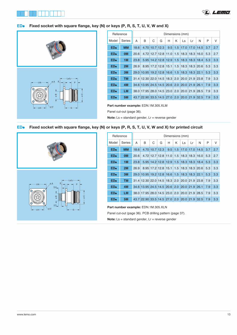
EDl Fixed socket with square flange, key (N) or keys (P, R, S, T, U, V, W and X)
ø C
ø B
Ls/Lr
N K
Gø V
ø A P
HPart number example: EDN.1M.305.XLM
Panel cut-out (page 36).
Note: Ls = standard gender, Lr = reverse gender
A B C G H K Ls Lr N P V
Dimensions (mm)
18.6 4.70 10.7 12.3 9.5 1.5 17.0 17.0 14.5 3.7 2.7
20.6 4.72 12.7 12.8 11.0 1.5 18.3 18.3 16.0 5.3 2.7
23.8 5.95 14.2 12.8 12.9 1.5 18.3 18.3 18.4 5.3 3.3
26.9 8.95 17.2 12.8 15.1 1.5 18.3 18.3 20.6 5.3 3.3
29.0 10.95 19.2 12.8 16.6 1.5 18.3 18.3 22.1 5.3 3.3
31.4 12.30 22.0 14.5 18.3 2.0 20.0 21.9 23.8 7.9 3.3
34.6 13.95 24.5 14.5 20.6 2.0 20.0 21.9 26.1 7.9 3.3
38.0 17.95 28.0 14.5 23.0 2.0 20.0 21.9 28.5 7.9 3.3
43.7 22.90 33.5 14.5 27.0 2.0 20.0 21.9 32.5 7.9 3.3
Reference
Model Series
EDl MM
EDl 0M
EDl 1M
EDl 2M
EDl 3M
EDl TM
EDl 4M
EDl LM
EDl 5M
EDl Fixed socket with square flange, key (N) or keys (P, R, S, T, U, V, W and X) for printed circuit
ø C
ø B
Ls/Lr
K
G
5.4
4.5
PN
ø VH
ø A
Part number example: EDN.1M.305.XLN
Panel cut-out (page 36). PCB drilling pattern (page 37).
Note: Ls = standard gender, Lr = reverse gender
A B C G H K Ls Lr N P V
Dimensions (mm)
18.6 4.70 10.7 12.3 9.5 1.5 17.0 17.0 14.5 3.7 2.7
20.6 4.72 12.7 12.8 11.0 1.5 18.3 18.3 16.0 5.3 2.7
23.8 5.95 14.2 12.8 12.9 1.5 18.3 18.3 18.4 5.3 3.3
26.9 8.95 17.2 12.8 15.1 1.5 18.3 18.3 20.6 5.3 3.3
29.0 10.95 19.2 12.8 16.6 1.5 18.3 18.3 22.1 5.3 3.3
31.4 12.30 22.0 14.5 18.3 2.0 20.0 21.9 23.8 7.9 3.3
34.6 13.95 24.5 14.5 20.6 2.0 20.0 21.9 26.1 7.9 3.3
38.0 17.95 28.0 14.5 23.0 2.0 20.0 21.9 28.5 7.9 3.3
43.7 22.90 33.5 14.5 27.0 2.0 20.0 21.9 32.5 7.9 3.3
Reference
Model Series
EDl MM
EDl 0M
EDl 1M
EDl 2M
EDl 3M
EDl TM
EDl 4M
EDl LM
EDl 5M
® ®
14 www.lemo.com
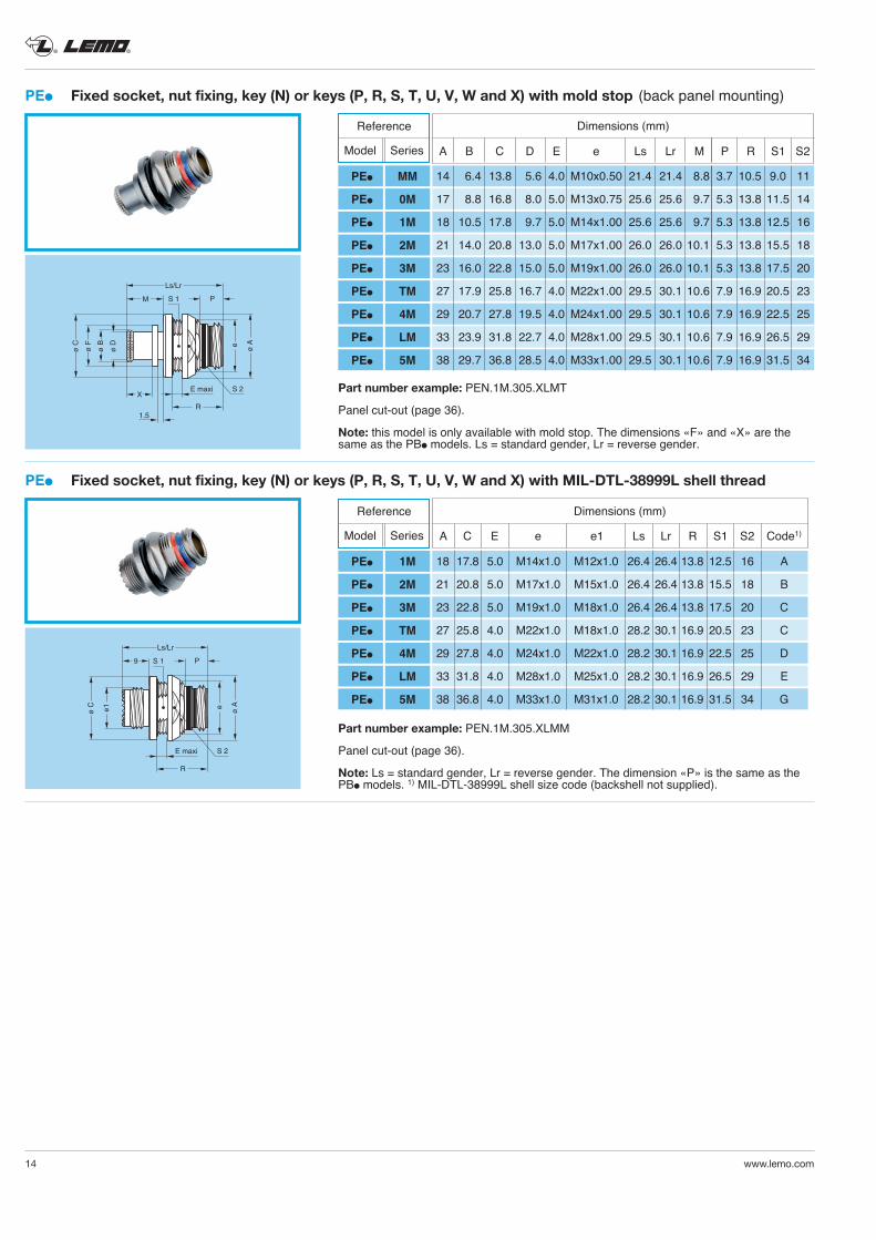
PEl Fixed socket, nut fixing, key (N) or keys (P, R, S, T, U, V, W and X) with mold stop (back panel mounting)
e ø A
Ls/Lr
P
R
E maxi S 2
ø B
ø F
ø C
ø D
M
X
1.5
S 1
Part number example: PEN.1M.305.XLMT
Panel cut-out (page 36).
Note: this model is only available with mold stop. The dimensions «F» and «X» are the same as the PBl models. Ls = standard gender, Lr = reverse gender.
A B C D E e Ls Lr M P R S1 S2
Dimensions (mm)
14 6.4 13.8 5.6 4.0 M10x0.50 21.4 21.4 8.8 3.7 10.5 9.0 11
17 8.8 16.8 8.0 5.0 M13x0.75 25.6 25.6 9.7 5.3 13.8 11.5 14
18 10.5 17.8 9.7 5.0 M14x1.00 25.6 25.6 9.7 5.3 13.8 12.5 16
21 14.0 20.8 13.0 5.0 M17x1.00 26.0 26.0 10.1 5.3 13.8 15.5 18
23 16.0 22.8 15.0 5.0 M19x1.00 26.0 26.0 10.1 5.3 13.8 17.5 20
27 17.9 25.8 16.7 4.0 M22x1.00 29.5 30.1 10.6 7.9 16.9 20.5 23
29 20.7 27.8 19.5 4.0 M24x1.00 29.5 30.1 10.6 7.9 16.9 22.5 25
33 23.9 31.8 22.7 4.0 M28x1.00 29.5 30.1 10.6 7.9 16.9 26.5 29
38 29.7 36.8 28.5 4.0 M33x1.00 29.5 30.1 10.6 7.9 16.9 31.5 34
Reference
Model Series
PEl MM
PEl 0M
PEl 1M
PEl 2M
PEl 3M
PEl TM
PEl 4M
PEl LM
PEl 5M
PEl Fixed socket, nut fixing, key (N) or keys (P, R, S, T, U, V, W and X) with MIL-DTL-38999L shell thread
e ø A
Ls/Lr
P
R
E maxi S 2
ø C
S 1
e1
9
Part number example: PEN.1M.305.XLMM
Panel cut-out (page 36).
Note: Ls = standard gender, Lr = reverse gender. The dimension «P» is the same as the PBl models. 1) MIL-DTL-38999L shell size code (backshell not supplied).
Dimensions (mm)
18 17.8 5.0 M14x1.0 M12x1.0 26.4 26.4 13.8 12.5 16 A
21 20.8 5.0 M17x1.0 M15x1.0 26.4 26.4 13.8 15.5 18 B
23 22.8 5.0 M19x1.0 M18x1.0 26.4 26.4 13.8 17.5 20 C
27 25.8 4.0 M22x1.0 M18x1.0 28.2 30.1 16.9 20.5 23 C
29 27.8 4.0 M24x1.0 M22x1.0 28.2 30.1 16.9 22.5 25 D
33 31.8 4.0 M28x1.0 M25x1.0 28.2 30.1 16.9 26.5 29 E
38 36.8 4.0 M33x1.0 M31x1.0 28.2 30.1 16.9 31.5 34 G
A C E e e1 Ls Lr R S1 S2 Code1)
Reference
Model Series
PEl 1M
PEl 2M
PEl 3M
PEl TM
PEl 4M
PEl LM
PEl 5M
® ®
www.lemo.com 15
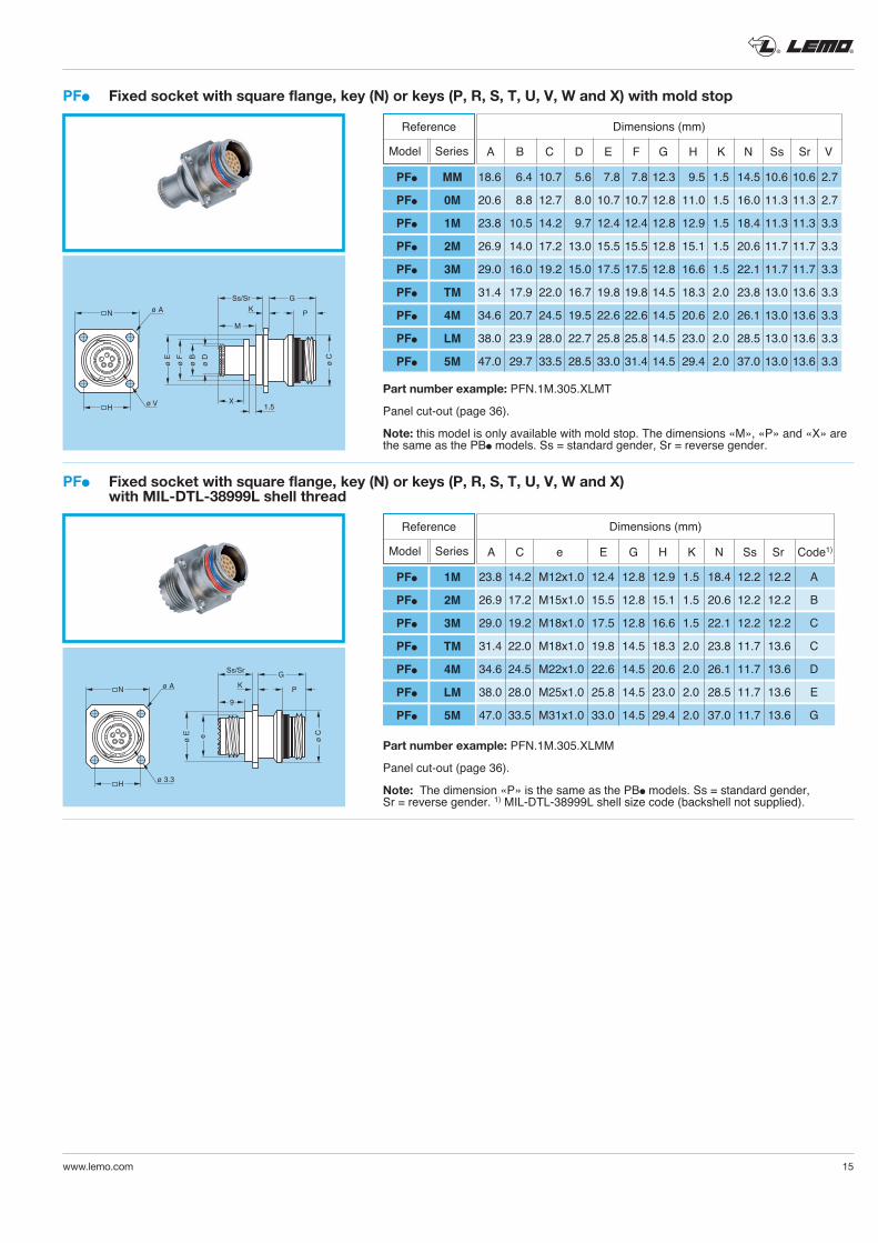
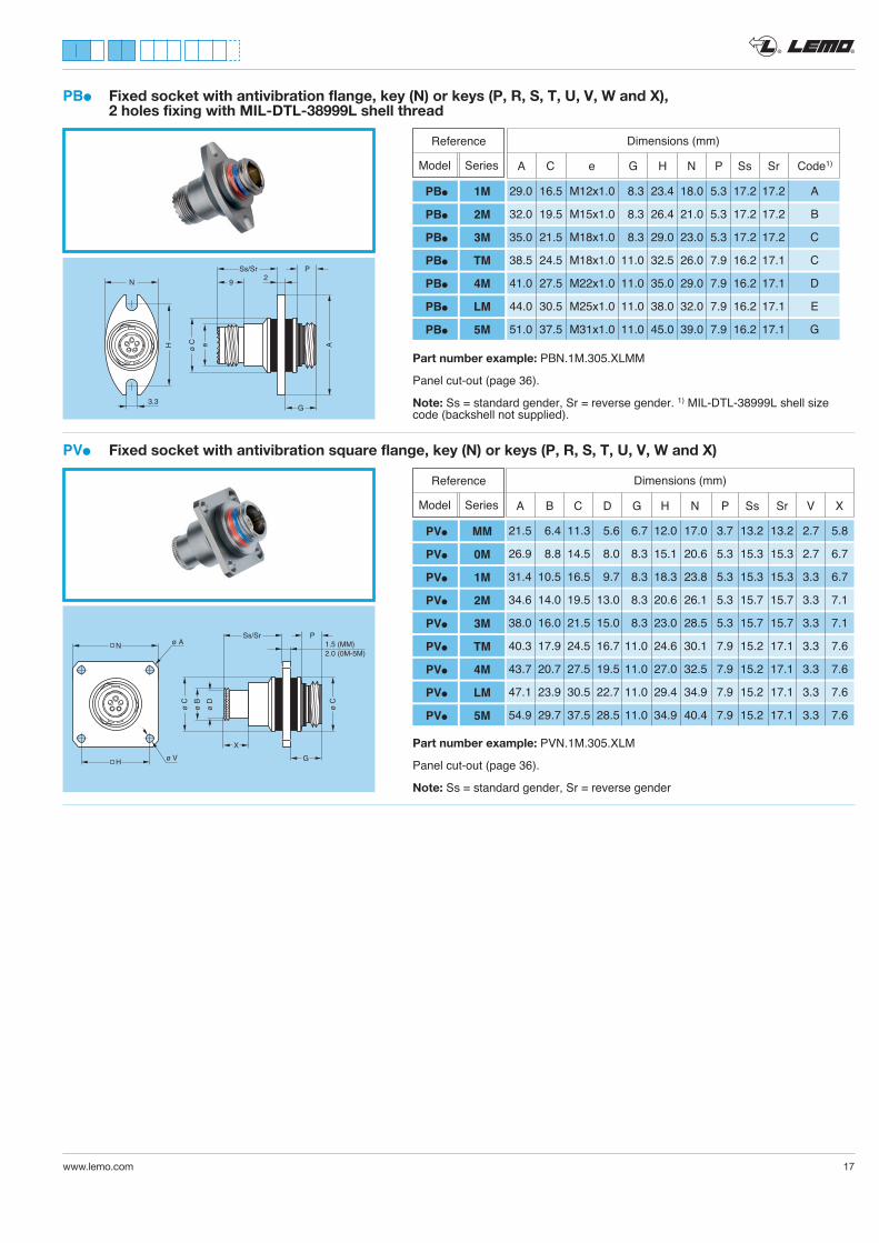
PFl Fixed socket with square flange, key (N) or keys (P, R, S, T, U, V, W and X) with MIL-DTL-38999L shell thread
eø E
9
ø C
Ss/SrG
K PN
ø 3.3
ø A
H
Part number example: PFN.1M.305.XLMM
Panel cut-out (page 36).
Note: The dimension «P» is the same as the PBl models. Ss = standard gender, Sr = reverse gender. 1) MIL-DTL-38999L shell size code (backshell not supplied).
Dimensions (mm)
A C e E G H K N Ss Sr Code1)
23.8 14.2 M12x1.0 12.4 12.8 12.9 1.5 18.4 12.2 12.2 A
26.9 17.2 M15x1.0 15.5 12.8 15.1 1.5 20.6 12.2 12.2 B
29.0 19.2 M18x1.0 17.5 12.8 16.6 1.5 22.1 12.2 12.2 C
31.4 22.0 M18x1.0 19.8 14.5 18.3 2.0 23.8 11.7 13.6 C
34.6 24.5 M22x1.0 22.6 14.5 20.6 2.0 26.1 11.7 13.6 D
38.0 28.0 M25x1.0 25.8 14.5 23.0 2.0 28.5 11.7 13.6 E
47.0 33.5 M31x1.0 33.0 14.5 29.4 2.0 37.0 11.7 13.6 G
Reference
Model Series
PFl 1M
PFl 2M
PFl 3M
PFl TM
PFl 4M
PFl LM
PFl 5M
PFl Fixed socket with square flange, key (N) or keys (P, R, S, T, U, V, W and X) with mold stop
ø B
ø F
ø E
ø D
X
M
1.5
ø C
Ss/Sr G
K PN
ø V
ø A
H
Part number example: PFN.1M.305.XLMT
Panel cut-out (page 36).
Note: this model is only available with mold stop. The dimensions «M», «P» and «X» are the same as the PBl models. Ss = standard gender, Sr = reverse gender.
A B C D E F G H K N Ss Sr V
Dimensions (mm)Reference
Model Series
PFl MM
PFl 0M
PFl 1M
PFl 2M
PFl 3M
PFl TM
PFl 4M
PFl LM
PFl 5M
18.6 6.4 10.7 5.6 7.8 7.8 12.3 9.5 1.5 14.5 10.6 10.6 2.7
20.6 8.8 12.7 8.0 10.7 10.7 12.8 11.0 1.5 16.0 11.3 11.3 2.7
23.8 10.5 14.2 9.7 12.4 12.4 12.8 12.9 1.5 18.4 11.3 11.3 3.3
26.9 14.0 17.2 13.0 15.5 15.5 12.8 15.1 1.5 20.6 11.7 11.7 3.3
29.0 16.0 19.2 15.0 17.5 17.5 12.8 16.6 1.5 22.1 11.7 11.7 3.3
31.4 17.9 22.0 16.7 19.8 19.8 14.5 18.3 2.0 23.8 13.0 13.6 3.3
34.6 20.7 24.5 19.5 22.6 22.6 14.5 20.6 2.0 26.1 13.0 13.6 3.3
38.0 23.9 28.0 22.7 25.8 25.8 14.5 23.0 2.0 28.5 13.0 13.6 3.3
47.0 29.7 33.5 28.5 33.0 31.4 14.5 29.4 2.0 37.0 13.0 13.6 3.3
® ®
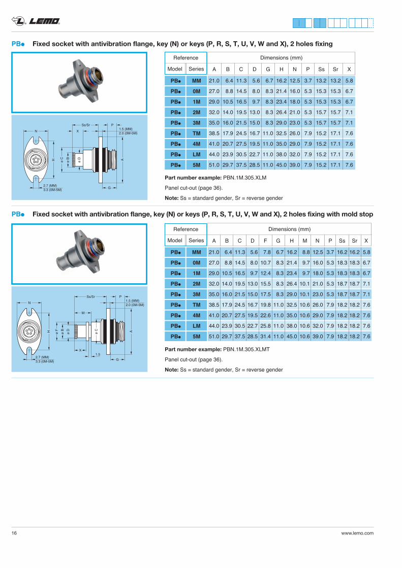
PBl Fixed socket with antivibration flange, key (N) or keys (P, R, S, T, U, V, W and X), 2 holes fixing with mold stop
Part number example: PBN.1M.305.XLMT
Panel cut-out (page 36).
Note: Ss = standard gender, Sr = reverse gender
A
Ss/Sr P
G
ø C
ø B
ø F
ø D
M
X1.5
N
H
2.7 (MM)3.3 (0M-5M)
1.5 (MM)2.0 (0M-5M)
Dimensions (mm)
A B C D F G H M N P Ss Sr X
Reference
Model Series
PBl MM
PBl 0M
PBl 1M
PBl 2M
PBl 3M
PBl TM
PBl 4M
PBl LM
PBl 5M
21.0 6.4 11.3 5.6 7.8 6.7 16.2 8.8 12.5 3.7 16.2 16.2 5.8
27.0 8.8 14.5 8.0 10.7 8.3 21.4 9.7 16.0 5.3 18.3 18.3 6.7
29.0 10.5 16.5 9.7 12.4 8.3 23.4 9.7 18.0 5.3 18.3 18.3 6.7
32.0 14.0 19.5 13.0 15.5 8.3 26.4 10.1 21.0 5.3 18.7 18.7 7.1
35.0 16.0 21.5 15.0 17.5 8.3 29.0 10.1 23.0 5.3 18.7 18.7 7.1
38.5 17.9 24.5 16.7 19.8 11.0 32.5 10.6 26.0 7.9 18.2 18.2 7.6
41.0 20.7 27.5 19.5 22.6 11.0 35.0 10.6 29.0 7.9 18.2 18.2 7.6
44.0 23.9 30.5 22.7 25.8 11.0 38.0 10.6 32.0 7.9 18.2 18.2 7.6
51.0 29.7 37.5 28.5 31.4 11.0 45.0 10.6 39.0 7.9 18.2 18.2 7.6
PBl Fixed socket with antivibration flange, key (N) or keys (P, R, S, T, U, V, W and X), 2 holes fixing
ASs/Sr
X
P
N
G
H
2.7 (MM)3.3 (0M-5M)
1.5 (MM)2.0 (0M-5M)
ø C
ø D
ø B
Part number example: PBN.1M.305.XLM
Panel cut-out (page 36).
Note: Ss = standard gender, Sr = reverse gender
Dimensions (mm)
A B C D G H N P Ss Sr X
21.0 6.4 11.3 5.6 6.7 16.2 12.5 3.7 13.2 13.2 5.8
27.0 8.8 14.5 8.0 8.3 21.4 16.0 5.3 15.3 15.3 6.7
29.0 10.5 16.5 9.7 8.3 23.4 18.0 5.3 15.3 15.3 6.7
32.0 14.0 19.5 13.0 8.3 26.4 21.0 5.3 15.7 15.7 7.1
35.0 16.0 21.5 15.0 8.3 29.0 23.0 5.3 15.7 15.7 7.1
38.5 17.9 24.5 16.7 11.0 32.5 26.0 7.9 15.2 17.1 7.6
41.0 20.7 27.5 19.5 11.0 35.0 29.0 7.9 15.2 17.1 7.6
44.0 23.9 30.5 22.7 11.0 38.0 32.0 7.9 15.2 17.1 7.6
51.0 29.7 37.5 28.5 11.0 45.0 39.0 7.9 15.2 17.1 7.6
Reference
Model Series
PBl MM
PBl 0M
PBl 1M
PBl 2M
PBl 3M
PBl TM
PBl 4M
PBl LM
PBl 5M
16 www.lemo.com
® ®
www.lemo.com 17
PVl Fixed socket with antivibration square flange, key (N) or keys (P, R, S, T, U, V, W and X)
ø C
Ss/Sr P
G
ø C
ø B
ø D
X
N
H ø V
ø A 1.5 (MM)2.0 (0M-5M)
Part number example: PVN.1M.305.XLM
Panel cut-out (page 36).
Note: Ss = standard gender, Sr = reverse gender
Dimensions (mm)
A B C D G H N P Ss Sr V X
21.5 6.4 11.3 5.6 6.7 12.0 17.0 3.7 13.2 13.2 2.7 5.8
26.9 8.8 14.5 8.0 8.3 15.1 20.6 5.3 15.3 15.3 2.7 6.7
31.4 10.5 16.5 9.7 8.3 18.3 23.8 5.3 15.3 15.3 3.3 6.7
34.6 14.0 19.5 13.0 8.3 20.6 26.1 5.3 15.7 15.7 3.3 7.1
38.0 16.0 21.5 15.0 8.3 23.0 28.5 5.3 15.7 15.7 3.3 7.1
40.3 17.9 24.5 16.7 11.0 24.6 30.1 7.9 15.2 17.1 3.3 7.6
43.7 20.7 27.5 19.5 11.0 27.0 32.5 7.9 15.2 17.1 3.3 7.6
47.1 23.9 30.5 22.7 11.0 29.4 34.9 7.9 15.2 17.1 3.3 7.6
54.9 29.7 37.5 28.5 11.0 34.9 40.4 7.9 15.2 17.1 3.3 7.6
Reference
Model Series
PVl MM
PVl 0M
PVl 1M
PVl 2M
PVl 3M
PVl TM
PVl 4M
PVl LM
PVl 5M
A
Ss/Sr P
N
G
2
H
3.3
9
ø C e
PBl Fixed socket with antivibration flange, key (N) or keys (P, R, S, T, U, V, W and X), 2 holes fixing with MIL-DTL-38999L shell thread
Part number example: PBN.1M.305.XLMM
Panel cut-out (page 36).
Note: Ss = standard gender, Sr = reverse gender. 1) MIL-DTL-38999L shell size code (backshell not supplied).
Dimensions (mm)
A C e G H N P Ss Sr Code1)
29.0 16.5 M12x1.0 8.3 23.4 18.0 5.3 17.2 17.2 A
32.0 19.5 M15x1.0 8.3 26.4 21.0 5.3 17.2 17.2 B
35.0 21.5 M18x1.0 8.3 29.0 23.0 5.3 17.2 17.2 C
38.5 24.5 M18x1.0 11.0 32.5 26.0 7.9 16.2 17.1 C
41.0 27.5 M22x1.0 11.0 35.0 29.0 7.9 16.2 17.1 D
44.0 30.5 M25x1.0 11.0 38.0 32.0 7.9 16.2 17.1 E
51.0 37.5 M31x1.0 11.0 45.0 39.0 7.9 16.2 17.1 G
Reference
Model Series
PBl 1M
PBl 2M
PBl 3M
PBl TM
PBl 4M
PBl LM
PBl 5M
® ®
18 www.lemo.com
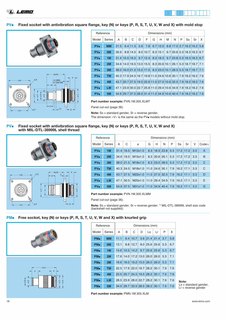
PVl Fixed socket with antivibration square flange, key (N) or keys (P, R, S, T, U, V, W and X) with MIL-DTL-38999L shell thread
ø C
Ss/Sr P
G
2
ø C
N
H ø V
ø A
e
9
Part number example: PVN.1M.305.XLMM
Panel cut-out (page 36).
Note: Ss = standard gender, Sr = reverse gender. 1) MIL-DTL-38999L shell size code (backshell not supplied).
PMl Free socket, key (N) or keys (P, R, S, T, U, V, W and X) with knurled grip
ø A
ø C
ø B
ø D
Ls/Lr
X P
Part number example: PMN.1M.305.XLM
Dimensions (mm)
31.4 16.5 M12x1.0 8.3 18.3 23.8 5.3 17.2 17.2 3.3 A
34.6 19.5 M15x1.0 8.3 20.6 26.1 5.3 17.2 17.2 3.3 B
38.0 21.5 M18x1.0 8.3 23.0 28.5 5.3 17.2 17.2 3.3 C
40.3 24.5 M18x1.0 11.0 24.6 30.1 7.9 16.2 17.1 3.3 C
43.7 27.5 M22x1.0 11.0 27.0 32.5 7.9 16.2 17.1 3.3 D
47.1 30.5 M25x1.0 11.0 29.4 34.9 7.9 16.2 17.1 3.3 E
54.9 37.5 M31x1.0 11.0 34.9 40.4 7.9 16.2 17.1 3.3 G
A C e G H N P Ss Sr V Code1)
Reference
Model Series
PVl 1M
PVl 2M
PVl 3M
PVl TM
PVl 4M
PVl LM
PVl 5M
Dimensions (mm)
11.1 6.4 10.7 5.6 21.4 21.4 3.7 5.8
13.1 8.8 12.7 8.0 25.6 25.6 5.3 6.7
14.6 10.5 14.2 9.7 25.6 25.6 5.3 6.7
17.6 14.0 17.2 13.0 26.0 26.0 5.3 7.1
19.6 16.0 19.2 15.0 26.0 26.0 5.3 7.1
22.5 17.9 22.0 16.7 28.2 30.1 7.9 7.6
25.0 20.7 24.5 19.5 28.2 30.1 7.9 7.6
28.5 23.9 28.0 22.7 28.2 30.1 7.9 7.6
34.0 29.7 33.5 28.5 28.2 30.1 7.9 7.6
A B C D Ls Lr P X
Reference
Model Series
PMl MM
PMl 0M
PMl 1M
PMl 2M
PMl 3M
PMl TM
PMl 4M
PMl LM
PMl 5M
PVl Fixed socket with antivibration square flange, key (N) or keys (P, R, S, T, U, V, W and X) with mold stop
ø C
Ss/Sr
P
G
ø C
ø B
ø F
ø D
M
X1.5
N
H ø V
ø A 1.5 (MM)2.0 (0M-5M)
Part number example: PVN.1M.305.XLMT
Panel cut-out (page 36).
Note: Ss = standard gender, Sr = reverse gender.The dimension «V» is the same as the PVl models without mold stop.
Dimensions (mm)
A B C D F G H M N P Ss Sr X
21.5 6.4 11.3 5.6 7.8 6.7 12.0 8.8 17.0 3.7 16.2 16.2 5.8
26.9 8.8 14.5 8.0 10.7 8.3 15.1 9.7 20.6 5.3 18.3 18.3 6.7
31.4 10.5 16.5 9.7 12.4 8.3 18.3 9.7 23.8 5.3 18.3 18.3 6.7
34.6 14.0 19.5 13.0 15.5 8.3 20.6 10.1 26.1 5.3 18.7 18.7 7.1
38.0 16.0 21.5 15.0 17.5 8.3 23.0 10.1 28.5 5.3 18.7 18.7 7.1
40.3 17.9 24.5 16.7 19.8 11.0 24.6 10.6 30.1 7.9 18.2 18.2 7.6
43.7 20.7 27.5 19.5 22.6 11.0 27.0 10.6 32.5 7.9 18.2 18.2 7.6
47.1 23.9 30.5 22.7 25.8 11.0 29.4 10.6 34.9 7.9 18.2 18.2 7.6
54.9 29.7 37.5 28.5 31.4 11.0 34.9 10.6 40.4 7.9 18.2 18.2 7.6
Reference
Model Series
PVl MM
PVl 0M
PVl 1M
PVl 2M
PVl 3M
PVl TM
PVl 4M
PVl LM
PVl 5M
Note: Ls = standard gender, Lr = reverse gender
® ®
www.lemo.com 19
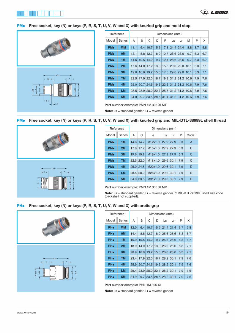
PMl Free socket, key (N) or keys (P, R, S, T, U, V, W and X) with knurled grip and mold stop
ø A
ø C
ø B
ø F
ø D
Ls/Lr
M P
X1.5 Part number example: PMN.1M.305.XLMT
Note: Ls = standard gender, Lr = reverse gender
PMl Free socket, key (N) or keys (P, R, S, T, U, V, W and X) with knurled grip and MIL-DTL-38999L shell thread
ø A
ø C
Ls/Lr
P
e
9
ø A
ø C
ø B
ø D
Ls/Lr
X P
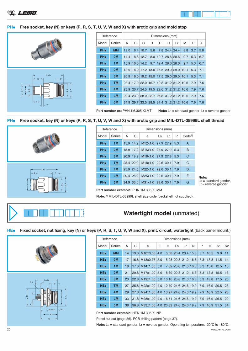
PHl Free socket, key (N) or keys (P, R, S, T, U, V, W and X) with arctic grip
Part number example: PHN.1M.305.XL
Note: Ls = standard gender, Lr = reverse gender
Part number example: PMN.1M.305.XLMM
Note: Ls = standard gender, Lr = reverse gender. 1) MIL-DTL-38999L shell size code (backshell not supplied).
Dimensions (mm)
A C e Ls Lr P Code1)
14.6 14.2 M12x1.0 27.9 27.9 5.3 A
17.6 17.2 M15x1.0 27.9 27.9 5.3 B
19.6 19.2 M18x1.0 27.9 27.9 5.3 C
22.5 22.0 M18x1.0 29.6 30.1 7.9 C
25.0 24.5 M22x1.0 29.6 30.1 7.9 D
28.5 28.0 M25x1.0 29.6 30.1 7.9 E
34.0 33.5 M31x1.0 29.6 30.1 7.9 G
Dimensions (mm)
A B C D F Ls Lr M P X
11.1 6.4 10.7 5.6 7.8 24.4 24.4 8.8 3.7 5.8
13.1 8.8 12.7 8.0 10.7 28.6 28.6 9.7 5.3 6.7
14.6 10.5 14.2 9.7 12.4 28.6 28.6 9.7 5.3 6.7
17.6 14.0 17.2 13.0 15.5 29.0 29.0 10.1 5.3 7.1
19.6 16.0 19.2 15.0 17.5 29.0 29.0 10.1 5.3 7.1
22.5 17.9 22.0 16.7 19.8 31.2 31.2 10.6 7.9 7.6
25.0 20.7 24.5 19.5 22.6 31.2 31.2 10.6 7.9 7.6
28.5 23.9 28.0 22.7 25.8 31.2 31.2 10.6 7.9 7.6
34.0 29.7 33.5 28.5 31.4 31.2 31.2 10.6 7.9 7.6
Reference
Model Series
PMl MM
PMl 0M
PMl 1M
PMl 2M
PMl 3M
PMl TM
PMl 4M
PMl LM
PMl 5M
Reference
Model Series
PMl 1M
PMl 2M
PMl 3M
PMl TM
PMl 4M
PMl LM
PMl 5M
Dimensions (mm)
A B C D Ls Lr P X
12.0 6.4 10.7 5.6 21.4 21.4 3.7 5.8
14.4 8.8 12.7 8.0 25.6 25.6 5.3 6.7
15.9 10.5 14.2 9.7 25.6 25.6 5.3 6.7
18.9 14.0 17.2 13.0 26.0 26.0 5.3 7.1
20.9 16.0 19.2 15.0 26.0 26.0 5.3 7.1
23.4 17.9 22.0 16.7 28.2 30.1 7.9 7.6
25.9 20.7 24.5 19.5 28.2 30.1 7.9 7.6
29.4 23.9 28.0 22.7 28.2 30.1 7.9 7.6
34.9 29.7 33.5 28.5 28.2 30.1 7.9 7.6
Reference
Model Series
PHl MM
PHl 0M
PHl 1M
PHl 2M
PHl 3M
PHl TM
PHl 4M
PHl LM
PHl 5M
® ®
20 www.lemo.com
PHl Free socket, key (N) or keys (P, R, S, T, U, V, W and X) with arctic grip and MIL-DTL-38999L shell thread
ø A
ø C
Ls/Lr
P
e
9
Part number example: PHN.1M.305.XLMM
Note: 1) MIL-DTL-38999L shell size code (backshell not supplied).
Dimensions (mm)
A C e Ls Lr P Code1)
15.9 14.2 M12x1.0 27.9 27.9 5.3 A
18.9 17.2 M15x1.0 27.9 27.9 5.3 B
20.9 19.2 M18x1.0 27.9 27.9 5.3 C
23.4 22.0 M18x1.0 29.6 30.1 7.9 C
25.9 24.5 M22x1.0 29.6 30.1 7.9 D
29.4 28.0 M25x1.0 29.6 30.1 7.9 E
34.9 33.5 M31x1.0 29.6 30.1 7.9 G
Reference
Model Series
PHl 1M
PHl 2M
PHl 3M
PHl TM
PHl 4M
PHl LM
PHl 5M
HEl Fixed socket, nut fixing, key (N) or keys (P, R, S, T, U, V, W and X), print. circuit, watertight (back panel mount.)
e ø A
H
ø C
Ls/Lr
P3
R
E maxi
N
S 1
S 2
Part number example: HEN.1M.305.XLNP Panel cut-out (page 36). PCB drilling pattern (page 37).Note: Ls = standard gender, Lr = reverse gender. Operating temperature: -20°C to +80°C.
Watertight model (unmated)
Dimensions (mm)
A C e E H Ls Lr N P R S1 S2
14 13.8 M10x0.50 4.0 5.08 20.4 20.4 15.3 3.7 10.5 9.0 11
17 16.8 M13x0.75 5.0 5.08 20.8 21.0 16.8 5.3 13.8 11.5 14
18 17.8 M14x1.00 5.0 7.62 20.8 21.0 16.8 5.3 13.8 12.5 16
21 20.8 M17x1.00 5.0 8.89 20.8 21.0 16.8 5.3 13.8 15.5 18
23 22.8 M19x1.00 5.0 10.16 20.8 21.0 16.8 5.3 13.8 17.5 20
27 25.8 M22x1.00 4.0 12.70 24.6 24.6 19.9 7.9 16.9 20.5 23
29 27.8 M24x1.00 4.0 13.97 24.6 24.6 19.9 7.9 16.9 22.5 25
33 31.8 M28x1.00 4.0 16.51 24.6 24.6 19.9 7.9 16.9 26.5 29
38 36.8 M33x1.00 4.0 20.32 24.6 24.6 19.9 7.9 16.9 31.5 34
Reference
Model Series
HEl MM
HEl 0M
HEl 1M
HEl 2M
HEl 3M
HEl TM
HEl 4M
HEl LM
HEl 5M
ø A
ø C
Ls/Lr
P
ø B
ø F
ø D
M
X1.5
PHl Free socket, key (N) or keys (P, R, S, T, U, V, W and X) with arctic grip and mold stop
Part number ex: PHN.1M.305.XLMT
Dimensions (mm)
A B C D F Ls Lr M P X
12.0 6.4 10.7 5.6 7.8 24.4 24.4 8.8 3.7 5.8
14.4 8.8 12.7 8.0 10.7 28.6 28.6 9.7 5.3 6.7
15.9 10.5 14.2 9.7 12.4 28.6 28.6 9.7 5.3 6.7
18.9 14.0 17.2 13.0 15.5 29.0 29.0 10.1 5.3 7.1
20.9 16.0 19.2 15.0 17.5 29.0 29.0 10.1 5.3 7.1
23.4 17.9 22.0 16.7 19.8 31.2 31.2 10.6 7.9 7.6
25.9 20.7 24.5 19.5 22.6 31.2 31.2 10.6 7.9 7.6
29.4 23.9 28.0 22.7 25.8 31.2 31.2 10.6 7.9 7.6
34.9 29.7 33.5 28.5 31.4 31.2 31.2 10.6 7.9 7.6
Reference
Model Series
PHl MM
PHl 0M
PHl 1M
PHl 2M
PHl 3M
PHl TM
PHl 4M
PHl LM
PHl 5M
Note: Ls = standard gender, Lr = reverse gender
Note: Ls = standard gender, Lr = reverse gender
® ®
www.lemo.com 21
ø A
ø C
L
P
S 1S 2
S 1S 2
ø A
ø C
L
P
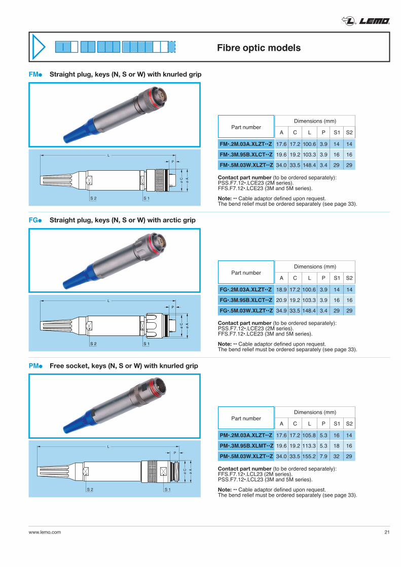
Contact part number (to be ordered separately):PSS.F7.12•.LCE23 (2M series).FFS.F7.12•.LCE23 (3M and 5M series).
Note: •• Cable adaptor defined upon request.The bend relief must be ordered separately (see page 33).
L
S 1S 2
ø A
ø C
P
FMl Straight plug, keys (N, S or W) with knurled grip
FGl Straight plug, keys (N, S or W) with arctic grip
PMl Free socket, keys (N, S or W) with knurled grip
Dimensions (mm)
A C L P S1 S2
FM•.2M.03A.XLZT••Z
FM•.3M.95B.XLCT••Z
FM•.5M.03W.XLZT••Z
17.6 17.2 100.6 3.9 14 14
19.6 19.2 103.3 3.9 16 16
34.0 33.5 148.4 3.4 29 29
Part number
Contact part number (to be ordered separately):PSS.F7.12•.LCE23 (2M series).FFS.F7.12•.LCE23 (3M and 5M series).
Note: •• Cable adaptor defined upon request.The bend relief must be ordered separately (see page 33).
Dimensions (mm)
A C L P S1 S2
FG•.2M.03A.XLZT••Z
FG•.3M.95B.XLCT••Z
FG•.5M.03W.XLZT••Z
18.9 17.2 100.6 3.9 14 14
20.9 19.2 103.3 3.9 16 16
34.9 33.5 148.4 3.4 29 29
Part number
Contact part number (to be ordered separately):FFS.F7.12•.LCL23 (2M series).PSS.F7.12•.LCL23 (3M and 5M series).
Note: •• Cable adaptor defined upon request.The bend relief must be ordered separately (see page 33).
Dimensions (mm)
A C L P S1 S2
PM•.2M.03A.XLZT••Z
PM•.3M.95B.XLMT••Z
PM•.5M.03W.XLZT••Z
17.6 17.2 105.8 5.3 16 14
19.6 19.2 113.3 5.3 18 16
34.0 33.5 155.2 7.9 32 29
Part number
Fibre optic models
® ®
22 www.lemo.com
ø Ce
L
P
DE maxiS 2
S 1
ø A
ø C
P
S 1S 2
L
ø C
ø B
L
N K
Gø 3.3
ø A P
H
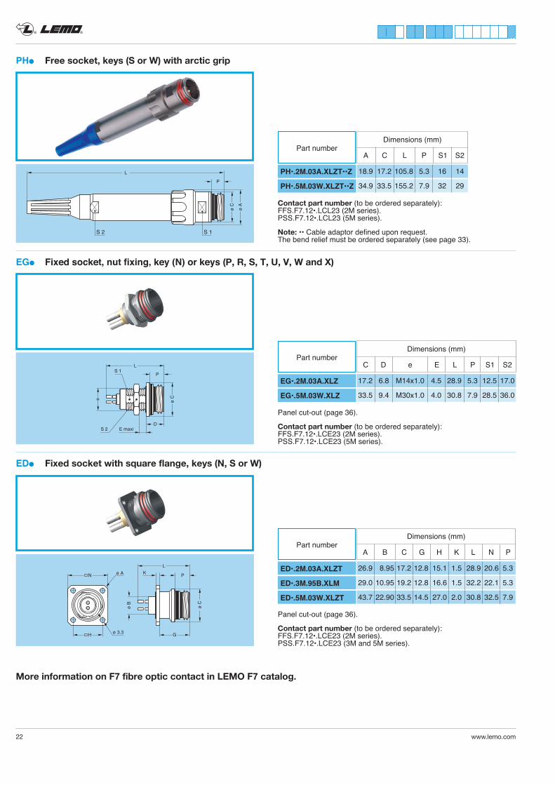
More information on F7 fibre optic contact in LEMO F7 catalog.
PHl Free socket, keys (S or W) with arctic grip
EGl Fixed socket, nut fixing, key (N) or keys (P, R, S, T, U, V, W and X)
EDl Fixed socket with square flange, keys (N, S or W)
Contact part number (to be ordered separately):FFS.F7.12•.LCL23 (2M series).PSS.F7.12•.LCL23 (5M series).
Note: •• Cable adaptor defined upon request.The bend relief must be ordered separately (see page 33).
Panel cut-out (page 36).
Contact part number (to be ordered separately):FFS.F7.12•.LCE23 (2M series).PSS.F7.12•.LCE23 (5M series).
Dimensions (mm)
EG•.2M.03A.XLZ
EG•.5M.03W.XLZ
Part number C D e E L P S1 S2
17.2 6.8 M14x1.0 4.5 28.9 5.3 12.5 17.0
33.5 9.4 M30x1.0 4.0 30.8 7.9 28.5 36.0
Panel cut-out (page 36).
Contact part number (to be ordered separately):FFS.F7.12•.LCE23 (2M series).PSS.F7.12•.LCE23 (3M and 5M series).
Dimensions (mm)
A B C G H K L N P
ED•.2M.03A.XLZT
ED•.3M.95B.XLM
ED•.5M.03W.XLZT
Part number
26.9 8.95 17.2 12.8 15.1 1.5 28.9 20.6 5.3
29.0 10.95 19.2 12.8 16.6 1.5 32.2 22.1 5.3
43.7 22.90 33.5 14.5 27.0 2.0 30.8 32.5 7.9
Dimensions (mm)
A C L P S1 S2
PH•.2M.03A.XLZT••Z
PH•.5M.03W.XLZT••Z
Part number
18.9 17.2 105.8 5.3 16 14
34.9 33.5 155.2 7.9 32 29
® ®
www.lemo.com 23
9/125 50/125 62.5/125
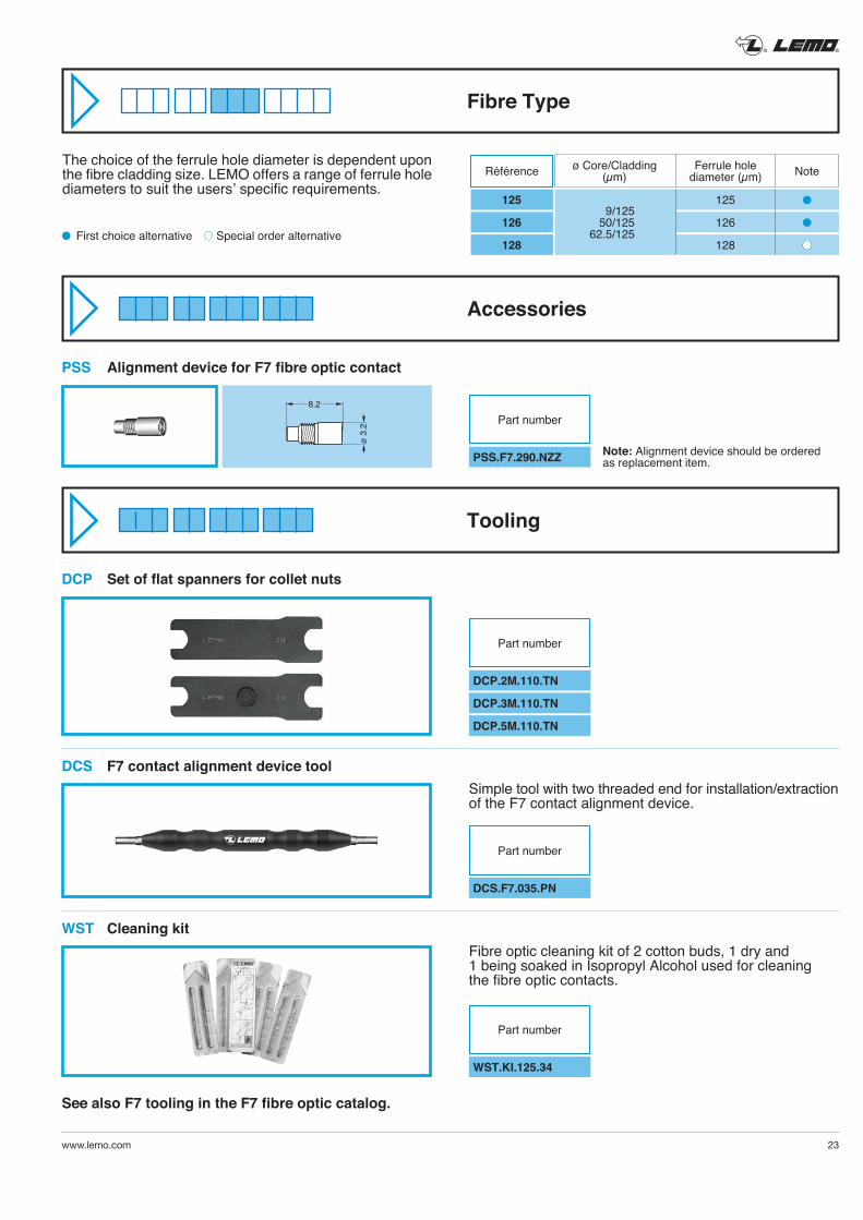
Note: Alignment device should be ordered as replacement item.
8.2
ø 3
.2
The choice of the ferrule hole diameter is dependent upon the fibre cladding size. LEMO offers a range of ferrule hole diameters to suit the users’ specific requirements.
l First choice alternative Special order alternative
Fibre Type
Accessories
See also F7 tooling in the F7 fibre optic catalog.
Tooling
Simple tool with two threaded end for installation/extraction of the F7 contact alignment device.
Fibre optic cleaning kit of 2 cotton buds, 1 dry and 1 being soaked in Isopropyl Alcohol used for cleaning the fibre optic contacts.
Référence ø Core/Cladding(µm)
Ferrule holediameter (µm) Note
125
126
128
l
l
l
125
126
128
PSS Alignment device for F7 fibre optic contact
PSS.F7.290.NZZ
Part number
DCP Set of flat spanners for collet nuts
DCS F7 contact alignment device tool
DCS.F7.035.PN
Part number
WST.KI.125.34
Part number
DCP.2M.110.TN
DCP.3M.110.TN
DCP.5M.110.TN
Part number
WST Cleaning kit
® ®
24 www.lemo.com
ø 2
9.4
ø 2
8
ø 2
3.9
ø 2
5.8
ø 2
2.7
31.6
10.6 3.4
7.6
1.5
ø 2
8
M 2
4 x
1
40.5
7.9
4 maxi
9.4
S 22.5
31
S 30
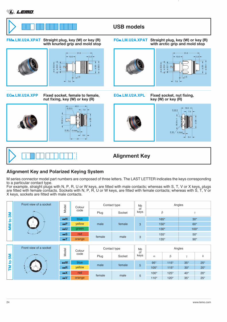
FMl.LM.U2A.XPAT Straight plug, key (W) or key (R) with knurled grip and mold stop
FGl.LM.U2A.XPAT Straight plug, key (W) or key (R) with arctic grip and mold stop
ø 2
8.5
ø 2
8
ø 2
3.9
ø 2
5.8
ø 2
2.7
31.6
10.6 3.4
7.6
1.5
ø 2
8
M 2
4 x
1
18.9
7.9
4 maxi
9.4
S 22.5
S 30
EGl.LM.U2A.XPP Fixed socket, female to female, nut fixing, key (W) or key (R)
EGl.LM.U2A.XPL Fixed socket, nut fixing, key (W) or key (R)
Alignment Key and Polarized Keying System M series connector model part numbers are composed of three letters. The LAST LETTER indicates the keys corresponding to a particular contact type. For example, straight plugs with N, P, R, U or W keys, are fitted with male contacts; whereas with S, T, V or X keys, plugs are fitted with female contacts. Sockets with N, P, R, U or W keys, are fitted with female contacts; whereas with S, T, V or X keys, sockets are fitted with male contacts.
165° 30° 150° 60° 130° 100°
Colourcode
3
Nb of
keysMod
el
γ
β
Front view of a socket
MM
to 3
M
llNllPllU
blueyellowgreen
male female
155° 50° 135° 90°
llSllT
redorange
female male 3
β γ
Angles
Plug Socket
Contact type
95° 115° 35° 25° 105° 115° 30° 20° 100° 125° 40° 20° 110° 120° 35° 25°
Colourcode
5
Nb of
keysMod
el
γ
β
δ
α
Front view of a socket
TM to
5M
llWllR
blueyellow
male female
llXllV
redorange
female male 5
α β γ δ
Angles
Plug Socket
Contact type
USB models
Alignment Key
® ®
www.lemo.com 25
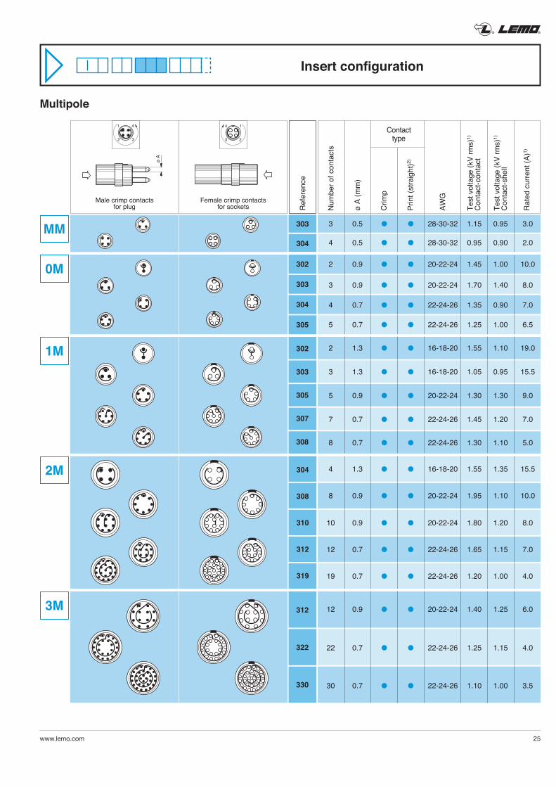
Multipole
Ref
eren
ce
ø A
Male crimp contactsfor plug
Female crimp contactsfor sockets N
umbe
r of c
onta
cts
ø A
(mm
)
Crim
p
Prin
t (st
raig
ht)2)
AWG
Test
vol
tage
(kV
rms)
1)
Con
tact
-con
tact
Test
vol
tage
(kV
rms)
1)
Con
tact
-she
ll
Rat
ed c
urre
nt (A
)1)
Contacttype
3 0.5 l l 28-30-32 1.15 0.95 3.0
4 0.5 l l 28-30-32 0.95 0.90 2.0
2 0.9 l l 20-22-24 1.45 1.00 10.0
3 0.9 l l 20-22-24 1.70 1.40 8.0
4 0.7 l l 22-24-26 1.35 0.90 7.0
5 0.7 l l 22-24-26 1.25 1.00 6.5
2 1.3 l l 16-18-20 1.55 1.10 19.0
3 1.3 l l 16-18-20 1.05 0.95 15.5
5 0.9 l l 20-22-24 1.30 1.30 9.0
7 0.7 l l 22-24-26 1.45 1.20 7.0
8 0.7 l l 22-24-26 1.30 1.10 5.0
4 1.3 l l 16-18-20 1.55 1.35 15.5
8 0.9 l l 20-22-24 1.95 1.10 10.0
10 0.9 l l 20-22-24 1.80 1.20 8.0
12 0.7 l l 22-24-26 1.65 1.15 7.0
19 0.7 l l 22-24-26 1.20 1.00 4.0
12 0.9 l l 20-22-24 1.40 1.25 6.0
22 0.7 l l 22-24-26 1.25 1.15 4.0
30 0.7 l l 22-24-26 1.10 1.00 3.5
14
23
1 4
2 3
Insert configuration
MM
0M
1M
2M
3M
303
304
302
303
304
305
302
303
305
307
308
304
308
310
312
319
312
322
330
® ®
26 www.lemo.com
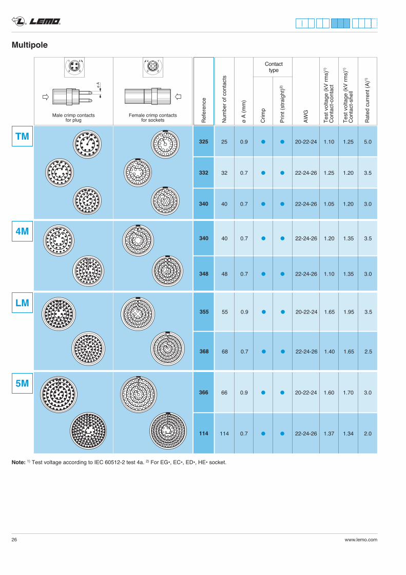
Multipole
Note: 1) Test voltage according to IEC 60512-2 test 4a. 2) For EG•, EC•, ED•, HE• socket.
ø A
Male crimp contactsfor plug
Female crimp contactsfor sockets N
umbe
r of c
onta
cts
ø A
(mm
)
Crim
p
Prin
t (st
raig
ht)2)
AWG
Test
vol
tage
(kV
rms)
1)
Con
tact
-con
tact
Test
vol
tage
(kV
rms)
1)
Con
tact
-she
ll
Rat
ed c
urre
nt (A
)1)
Contacttype
14
23
1 4
2 3
25 0.9 l l 20-22-24 1.10 1.25 5.0
32 0.7 l l 22-24-26 1.25 1.20 3.5
40 0.7 l l 22-24-26 1.05 1.20 3.0
TM
4M
LM
5M
Ref
eren
ce
325
332
340
66 0.9 l l 20-22-24 1.60 1.70 3.0
114 0.7 l l 22-24-26 1.37 1.34 2.0
366
114
40 0.7 l l 22-24-26 1.20 1.35 3.5
48 0.7 l l 22-24-26 1.10 1.35 3.0
340
348
55 0.9 l l 20-22-24 1.65 1.95 3.5
68 0.7 l l 22-24-26 1.40 1.65 2.5
355
368
® ®
www.lemo.com 27
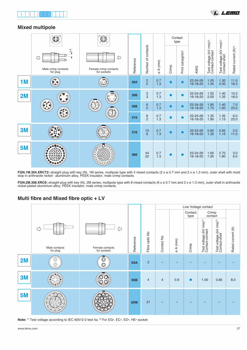
Mixed multipole
Ref
eren
ce
ø A
Male crimp contactsfor plug
Female crimp contactsfor sockets N
umbe
r of c
onta
cts
ø A
(mm
)
Crim
p
Prin
t (st
raig
ht)2
)
AWG
Test
vol
tage
(kV
rms)
1)C
onta
ct-c
onta
ct
Test
vol
tage
(kV
rms)
1)C
onta
ct-s
hell
Rat
ed c
urre
nt (A
)1)
Contacttype
14
23
1 4
2 3
2M
1M 304
306
308
310
2 0.7 22-24-26 1.20 1.30 11.0 l l 2 1.3 16-18-20 1.45 2.00 18.5
Note: 1) Test voltage according to IEC 60512-2 test 4a. 2) For EG•, EC•, ED•, HE• socket.
Ref
eren
ce
Male contactsfor plug
Female contactsfor sockets
FGN.1M.304.XRCT2: straight plug with key (N), 1M series, multipole type with 4 mixed contacts (2 x ø 0.7 mm and 2 x ø 1.3 mm), outer shell with mold stop in anthracite nickel- aluminium alloy, PEEK insulator, male crimp contacts.
FGN.2M.308.XRC6: straight plug with key (N), 2M series, multipole type with 8 mixed contacts (6 x ø 0.7 mm and 2 x ø 1.3 mm), outer shell in anthracite nickel-plated aluminium alloy, PEEK insulator, male crimp contacts.
Fibr
e op
tic N
o
Con
tact
No
ø A
(mm
)
Crim
p
Test
vol
tage
(kV
rms)
1)
Con
tact
-con
tact
Test
vol
tage
(kV
rms)
1)
Con
tact
-she
ll
Rat
ed c
urre
nt (A
)
Low Voltage contact Contact Crimp type contact
Multi fibre and Mixed fibre optic + LV
03A
03W
95B
2M
3M
5M
2 – – – – – –
3M
5M
316
366
10 0.7 22-24-26 0.90 0.95 2.0 l l 6 1.3 16-18-20 1.35 1.15 11.0
44 0.7 22-24-26 1.65 2.70 3.0 l l 22 1.3 16-18-20 1.95 1.80 6.0
3 0.7 22-24-26 1.55 1.40 10.5 l l 3 1.3 16-18-20 2.05 1.35 18.0
6 0.7 22-24-26 1.95 1.40 7.0 l l 2 1.3 16-18-20 1.75 1.60 23.0
8 0.7 22-24-26 1.35 1.35 6.0 l l 2 1.3 16-18-20 1.90 1.15 23.0
4 4 0.9 l 1.00 0.80 8.0
21 – – – – – –
® ®
28 www.lemo.com
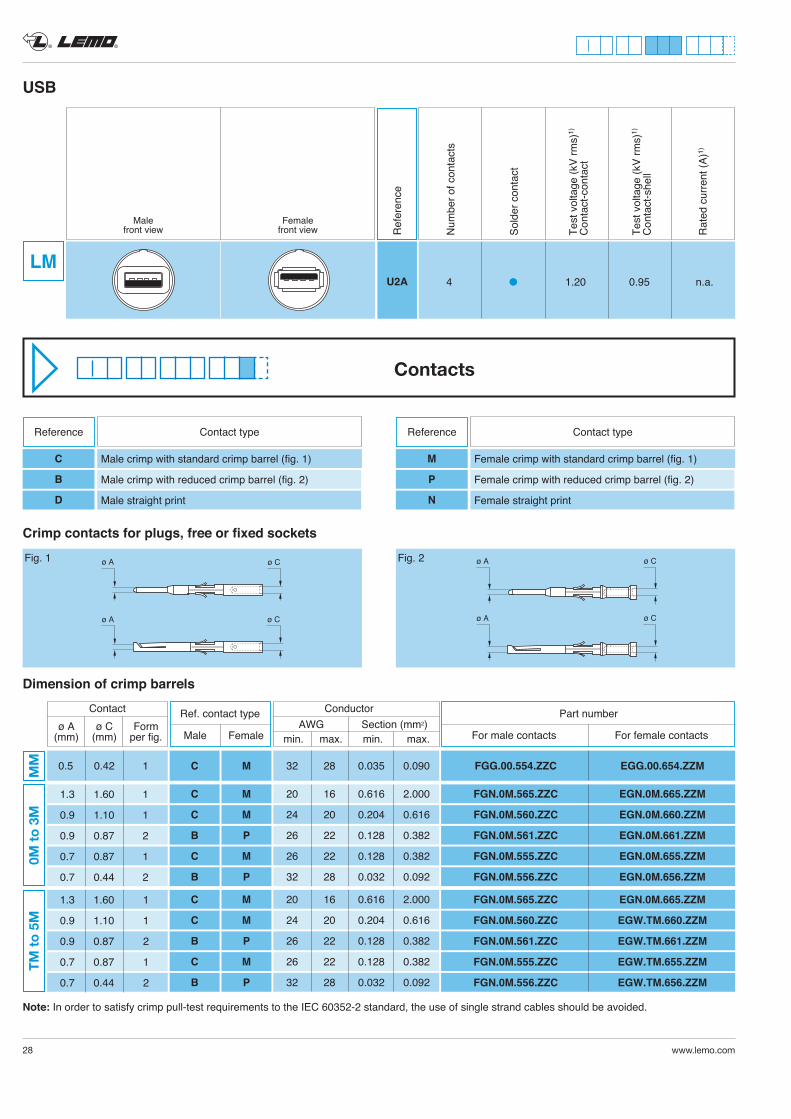
Crimp contacts for plugs, free or fixed sockets
Dimension of crimp barrels
ø A
ø A
ø C
ø C
Fig. 1 ø A ø C
ø A ø C
Fig. 2
Contacts
Note: In order to satisfy crimp pull-test requirements to the IEC 60352-2 standard, the use of single strand cables should be avoided.
U2A 4 l 1.20 0.95 n.a.
USB
Ref
eren
ce
Malefront view
Femalefront view N
umbe
r of c
onta
cts
Sold
er c
onta
ct
Test
vol
tage
(kV
rms)
1)
Con
tact
-con
tact
Test
vol
tage
(kV
rms)
1)
Con
tact
-she
ll
Rat
ed c
urre
nt (A
)1)
LM
Reference Contact type
C
B
D
Male crimp with standard crimp barrel (fig. 1)
Male crimp with reduced crimp barrel (fig. 2)
Male straight print
Reference Contact type
M
P
N
Female crimp with standard crimp barrel (fig. 1)
Female crimp with reduced crimp barrel (fig. 2)
Female straight print
Conductor AWG Section (mm2) min. max. min. max.
Contact ø A ø C Form (mm) (mm) per fig.
0.5 0.42 1MM C M
1.3 1.60 1
0.9 1.10 1
0.9 0.87 2
0.7 0.87 1
0.7 0.44 2
0M to
3M
C
C
B
C
B
M
M
P
M
P
TM to
5M
C
C
B
C
B
M
M
P
M
P
1.3 1.60 1
0.9 1.10 1
0.9 0.87 2
0.7 0.87 1
0.7 0.44 2
20 16 0.616 2.000
24 20 0.204 0.616
26 22 0.128 0.382
26 22 0.128 0.382
32 28 0.032 0.092
20 16 0.616 2.000
24 20 0.204 0.616
26 22 0.128 0.382
26 22 0.128 0.382
32 28 0.032 0.092
32 28 0.035 0.090
For male contacts For female contacts
FGN.0M.565.ZZC EGN.0M.665.ZZM
FGN.0M.560.ZZC EGN.0M.660.ZZM
FGN.0M.561.ZZC EGN.0M.661.ZZM
FGN.0M.555.ZZC EGN.0M.655.ZZM
FGN.0M.556.ZZC EGN.0M.656.ZZM
FGG.00.554.ZZC EGG.00.654.ZZM
FGN.0M.565.ZZC EGN.0M.665.ZZM
FGN.0M.560.ZZC EGW.TM.660.ZZM
FGN.0M.561.ZZC EGW.TM.661.ZZM
FGN.0M.555.ZZC EGW.TM.655.ZZM
FGN.0M.556.ZZC EGW.TM.656.ZZM
Male Female
Ref. contact type Part number
® ®
www.lemo.com 29
sliding loop
L
XN
P
ø C
ø A
sliding loop
L
X
N
P
ø C
ø A
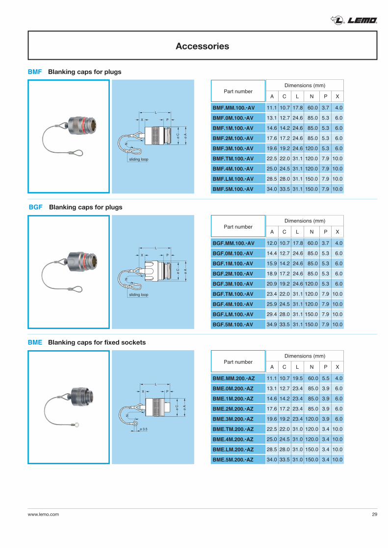
Accessories
L
X P
ø C
ø A
N
ø 3.5
BMF Blanking caps for plugs
BGF Blanking caps for plugs
BME Blanking caps for fixed sockets
Dimensions (mm)
BMF.MM.100.•AV
BMF.0M.100.•AV
BMF.1M.100.•AV
BMF.2M.100.•AV
BMF.3M.100.•AV
BMF.TM.100.•AV
BMF.4M.100.•AV
BMF.LM.100.•AV
BMF.5M.100.•AV
Part number
11.1 10.7 17.8 60.0 3.7 4.0
13.1 12.7 24.6 85.0 5.3 6.0
14.6 14.2 24.6 85.0 5.3 6.0
17.6 17.2 24.6 85.0 5.3 6.0
19.6 19.2 24.6 120.0 5.3 6.0
22.5 22.0 31.1 120.0 7.9 10.0
25.0 24.5 31.1 120.0 7.9 10.0
28.5 28.0 31.1 150.0 7.9 10.0
34.0 33.5 31.1 150.0 7.9 10.0
A C L N P X
Dimensions (mm)
BGF.MM.100.•AV
BGF.0M.100.•AV
BGF.1M.100.•AV
BGF.2M.100.•AV
BGF.3M.100.•AV
BGF.TM.100.•AV
BGF.4M.100.•AV
BGF.LM.100.•AV
BGF.5M.100.•AV
Part number
12.0 10.7 17.8 60.0 3.7 4.0
14.4 12.7 24.6 85.0 5.3 6.0
15.9 14.2 24.6 85.0 5.3 6.0
18.9 17.2 24.6 85.0 5.3 6.0
20.9 19.2 24.6 120.0 5.3 6.0
23.4 22.0 31.1 120.0 7.9 10.0
25.9 24.5 31.1 120.0 7.9 10.0
29.4 28.0 31.1 150.0 7.9 10.0
34.9 33.5 31.1 150.0 7.9 10.0
A C L N P X
Dimensions (mm)
BME.MM.200.•AZ
BME.0M.200.•AZ
BME.1M.200.•AZ
BME.2M.200.•AZ
BME.3M.200.•AZ
BME.TM.200.•AZ
BME.4M.200.•AZ
BME.LM.200.•AZ
BME.5M.200.•AZ
Part number
11.1 10.7 19.5 60.0 5.5 4.0
13.1 12.7 23.4 85.0 3.9 6.0
14.6 14.2 23.4 85.0 3.9 6.0
17.6 17.2 23.4 85.0 3.9 6.0
19.6 19.2 23.4 120.0 3.9 6.0
22.5 22.0 31.0 120.0 3.4 10.0
25.0 24.5 31.0 120.0 3.4 10.0
28.5 28.0 31.0 150.0 3.4 10.0
34.0 33.5 31.0 150.0 3.4 10.0
A C L N P X
® ®
30 www.lemo.com
L
X P
ø C
ø A
N
ø 3.5
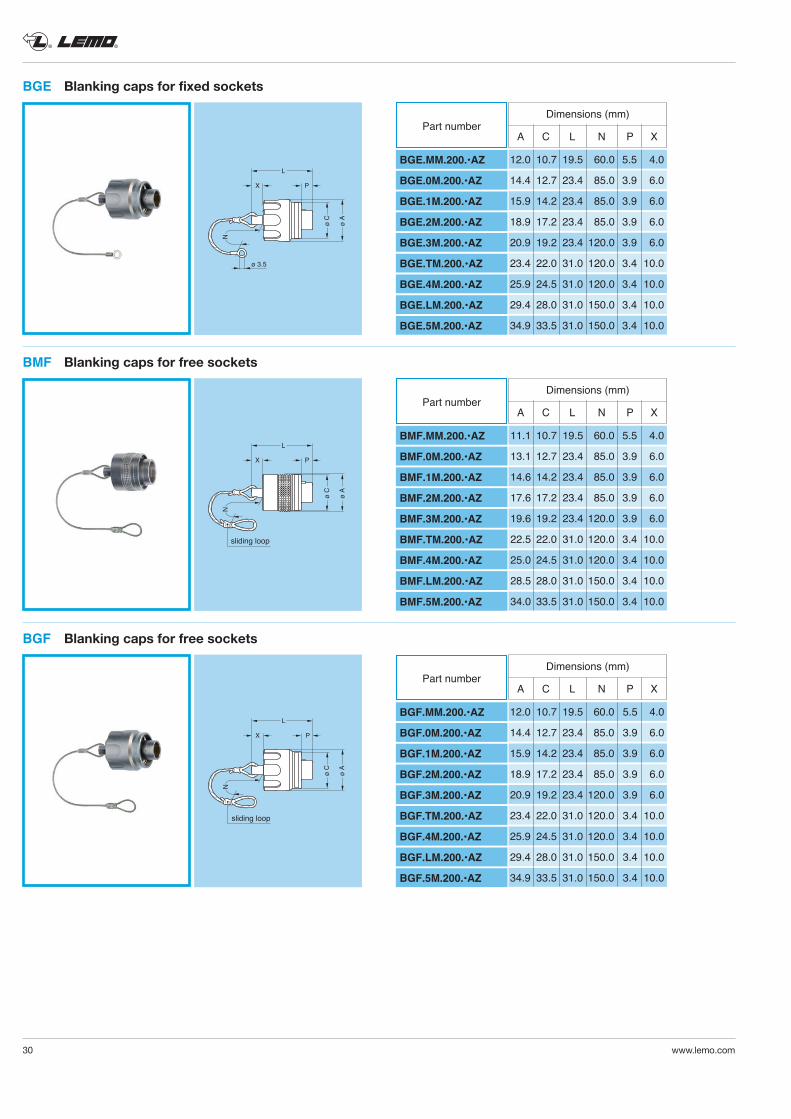
BGE Blanking caps for fixed sockets
Dimensions (mm)
BGE.MM.200.•AZ
BGE.0M.200.•AZ
BGE.1M.200.•AZ
BGE.2M.200.•AZ
BGE.3M.200.•AZ
BGE.TM.200.•AZ
BGE.4M.200.•AZ
BGE.LM.200.•AZ
BGE.5M.200.•AZ
Part number
12.0 10.7 19.5 60.0 5.5 4.0
14.4 12.7 23.4 85.0 3.9 6.0
15.9 14.2 23.4 85.0 3.9 6.0
18.9 17.2 23.4 85.0 3.9 6.0
20.9 19.2 23.4 120.0 3.9 6.0
23.4 22.0 31.0 120.0 3.4 10.0
25.9 24.5 31.0 120.0 3.4 10.0
29.4 28.0 31.0 150.0 3.4 10.0
34.9 33.5 31.0 150.0 3.4 10.0
A C L N P X
sliding loop
L
X
N
P
ø C
ø A
BMF Blanking caps for free sockets
Dimensions (mm)
BMF.MM.200.•AZ
BMF.0M.200.•AZ
BMF.1M.200.•AZ
BMF.2M.200.•AZ
BMF.3M.200.•AZ
BMF.TM.200.•AZ
BMF.4M.200.•AZ
BMF.LM.200.•AZ
BMF.5M.200.•AZ
Part number
11.1 10.7 19.5 60.0 5.5 4.0
13.1 12.7 23.4 85.0 3.9 6.0
14.6 14.2 23.4 85.0 3.9 6.0
17.6 17.2 23.4 85.0 3.9 6.0
19.6 19.2 23.4 120.0 3.9 6.0
22.5 22.0 31.0 120.0 3.4 10.0
25.0 24.5 31.0 120.0 3.4 10.0
28.5 28.0 31.0 150.0 3.4 10.0
34.0 33.5 31.0 150.0 3.4 10.0
A C L N P X
sliding loop
L
X
N
P
ø C
ø A
BGF Blanking caps for free sockets
Dimensions (mm)
BGF.MM.200.•AZ
BGF.0M.200.•AZ
BGF.1M.200.•AZ
BGF.2M.200.•AZ
BGF.3M.200.•AZ
BGF.TM.200.•AZ
BGF.4M.200.•AZ
BGF.LM.200.•AZ
BGF.5M.200.•AZ
Part number
12.0 10.7 19.5 60.0 5.5 4.0
14.4 12.7 23.4 85.0 3.9 6.0
15.9 14.2 23.4 85.0 3.9 6.0
18.9 17.2 23.4 85.0 3.9 6.0
20.9 19.2 23.4 120.0 3.9 6.0
23.4 22.0 31.0 120.0 3.4 10.0
25.9 24.5 31.0 120.0 3.4 10.0
29.4 28.0 31.0 150.0 3.4 10.0
34.9 33.5 31.0 150.0 3.4 10.0
A C L N P X
® ®
www.lemo.com 31
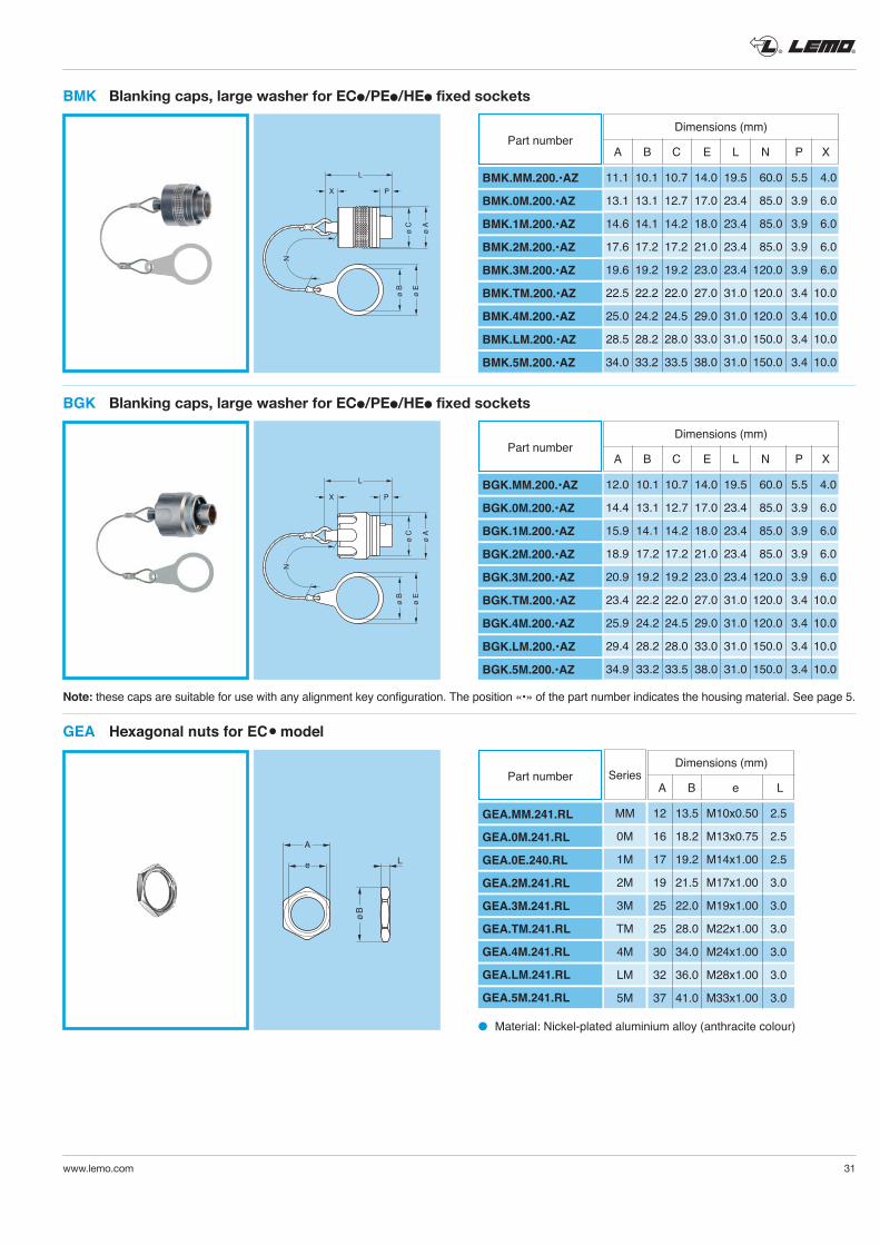
Note: these caps are suitable for use with any alignment key configuration. The position «•» of the part number indicates the housing material. See page 5.
ø B
ø E
L
X P
ø C
ø A
N
BMK Blanking caps, large washer for ECl/PEl/HEl fixed sockets
L
X P
ø C
ø A
ø B
ø E
N
BGK Blanking caps, large washer for ECl/PEl/HEl fixed sockets
Dimensions (mm)
BMK.MM.200.•AZ
BMK.0M.200.•AZ
BMK.1M.200.•AZ
BMK.2M.200.•AZ
BMK.3M.200.•AZ
BMK.TM.200.•AZ
BMK.4M.200.•AZ
BMK.LM.200.•AZ
BMK.5M.200.•AZ
Part number A B C E L N P X
11.1 10.1 10.7 14.0 19.5 60.0 5.5 4.0
13.1 13.1 12.7 17.0 23.4 85.0 3.9 6.0
14.6 14.1 14.2 18.0 23.4 85.0 3.9 6.0
17.6 17.2 17.2 21.0 23.4 85.0 3.9 6.0
19.6 19.2 19.2 23.0 23.4 120.0 3.9 6.0
22.5 22.2 22.0 27.0 31.0 120.0 3.4 10.0
25.0 24.2 24.5 29.0 31.0 120.0 3.4 10.0
28.5 28.2 28.0 33.0 31.0 150.0 3.4 10.0
34.0 33.2 33.5 38.0 31.0 150.0 3.4 10.0
Dimensions (mm)
BGK.MM.200.•AZ
BGK.0M.200.•AZ
BGK.1M.200.•AZ
BGK.2M.200.•AZ
BGK.3M.200.•AZ
BGK.TM.200.•AZ
BGK.4M.200.•AZ
BGK.LM.200.•AZ
BGK.5M.200.•AZ
Part number A B C E L N P X
12.0 10.1 10.7 14.0 19.5 60.0 5.5 4.0
14.4 13.1 12.7 17.0 23.4 85.0 3.9 6.0
15.9 14.1 14.2 18.0 23.4 85.0 3.9 6.0
18.9 17.2 17.2 21.0 23.4 85.0 3.9 6.0
20.9 19.2 19.2 23.0 23.4 120.0 3.9 6.0
23.4 22.2 22.0 27.0 31.0 120.0 3.4 10.0
25.9 24.2 24.5 29.0 31.0 120.0 3.4 10.0
29.4 28.2 28.0 33.0 31.0 150.0 3.4 10.0
34.9 33.2 33.5 38.0 31.0 150.0 3.4 10.0
e L
A
øB
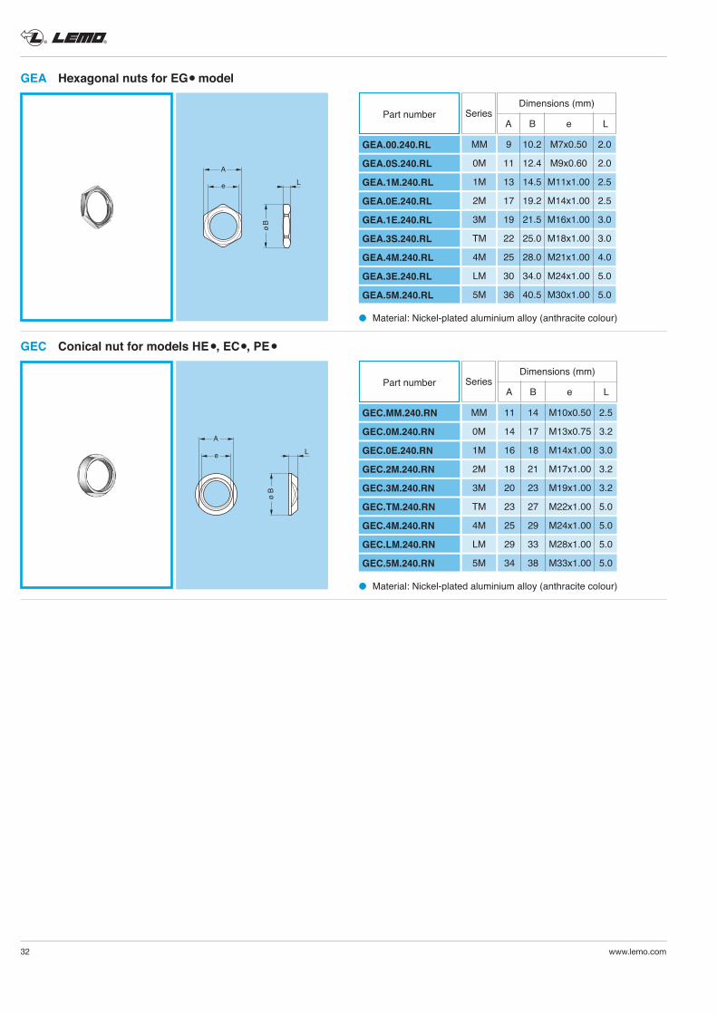
l Material: Nickel-plated aluminium alloy (anthracite colour)
GEA Hexagonal nuts for ECl model
GEA.MM.241.RL
GEA.0M.241.RL
GEA.0E.240.RL
GEA.2M.241.RL
GEA.3M.241.RL
GEA.TM.241.RL
GEA.4M.241.RL
GEA.LM.241.RL
GEA.5M.241.RL
Part numberDimensions (mm)
A B e LSeries
MM 12 13.5 M10x0.50 2.5
0M 16 18.2 M13x0.75 2.5
1M 17 19.2 M14x1.00 2.5
2M 19 21.5 M17x1.00 3.0
3M 25 22.0 M19x1.00 3.0
TM 25 28.0 M22x1.00 3.0
4M 30 34.0 M24x1.00 3.0
LM 32 36.0 M28x1.00 3.0
5M 37 41.0 M33x1.00 3.0
® ®
32 www.lemo.com
e L
A
øB
l Material: Nickel-plated aluminium alloy (anthracite colour)
l Material: Nickel-plated aluminium alloy (anthracite colour)
GEA Hexagonal nuts for EGl model
A
e L
ø B
GEC Conical nut for models HE l, ECl, PE l
Dimensions (mm)
GEA.00.240.RL
GEA.0S.240.RL
GEA.1M.240.RL
GEA.0E.240.RL
GEA.1E.240.RL
GEA.3S.240.RL
GEA.4M.240.RL
GEA.3E.240.RL
GEA.5M.240.RL
Part number A B e L
MM 9 10.2 M7x0.50 2.0
0M 11 12.4 M9x0.60 2.0
1M 13 14.5 M11x1.00 2.5
2M 17 19.2 M14x1.00 2.5
3M 19 21.5 M16x1.00 3.0
TM 22 25.0 M18x1.00 3.0
4M 25 28.0 M21x1.00 4.0
LM 30 34.0 M24x1.00 5.0
5M 36 40.5 M30x1.00 5.0
Series
Dimensions (mm)
GEC.MM.240.RN
GEC.0M.240.RN
GEC.0E.240.RN
GEC.2M.240.RN
GEC.3M.240.RN
GEC.TM.240.RN
GEC.4M.240.RN
GEC.LM.240.RN
GEC.5M.240.RN
Part number A B e L
Series
MM 11 14 M10x0.50 2.5
0M 14 17 M13x0.75 3.2
1M 16 18 M14x1.00 3.0
2M 18 21 M17x1.00 3.2
3M 20 23 M19x1.00 3.2
TM 23 27 M22x1.00 5.0
4M 25 29 M24x1.00 5.0
LM 29 33 M28x1.00 5.0
5M 34 38 M33x1.00 5.0
® ®
www.lemo.com 33
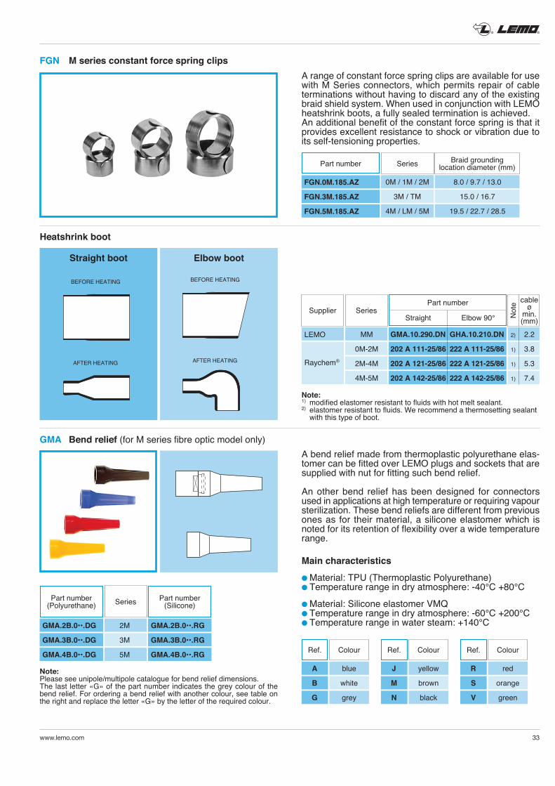
FGN M series constant force spring clips
AFTER HEATING
BEFORE HEATING
Straight boot
AFTER HEATING
BEFORE HEATING
Elbow boot
A bend relief made from thermoplastic polyurethane elas-tomer can be fitted over LEMO plugs and sockets that are supplied with nut for fitting such bend relief.
An other bend relief has been designed for connectors used in applications at high temperature or requiring vapour sterilization. These bend reliefs are different from previous ones as for their material, a silicone elastomer which is noted for its retention of flexibility over a wide temperature range.
Main characteristics
l Material: TPU (Thermoplastic Polyurethane)l Temperature range in dry atmosphere: -40°C +80°C
l Material: Silicone elastomer VMQl Temperature range in dry atmosphere: -60°C +200°Cl Temperature range in water steam: +140°C
Note:Please see unipole/multipole catalogue for bend relief dimensions.The last letter «G» of the part number indicates the grey colour of the bend relief. For ordering a bend relief with another colour, see table on the right and replace the letter «G» by the letter of the required colour.
Note: 1) modified elastomer resistant to fluids with hot melt sealant.2) elastomer resistant to fluids. We recommend a thermosetting sealant
with this type of boot.
A range of constant force spring clips are available for use with M Series connectors, which permits repair of cable terminations without having to discard any of the existing braid shield system. When used in conjunction with LEMO heatshrink boots, a fully sealed termination is achieved. An additional benefit of the constant force spring is that it provides excellent resistance to shock or vibration due to its self-tensioning properties.
Heatshrink boot
GMA Bend relief (for M series fibre optic model only)
SeriesPart number(Polyurethane)
Part number(Silicone)
GMA.2B.0••.DG 2M GMA.2B.0••.RG
GMA.3B.0••.DG 3M GMA.3B.0••.RG
GMA.4B.0••.DG 5M GMA.4B.0••.RG Ref. Colour
A blue
B white
G grey
Ref. Colour
J yellow
M brown
N black
Ref. Colour
R red
S orange
V green
StraightSupplier Series
Elbow 90° Not
e cableø
min. (mm)
LEMO
Raychem®
MM GMA.10.290.DN GHA.10.210.DN 2) 2.2
0M-2M 202 A 111-25/86 222 A 111-25/86 1) 3.8
2M-4M 202 A 121-25/86 222 A 121-25/86 1) 5.3
4M-5M 202 A 142-25/86 222 A 142-25/86 1) 7.4
FGN.0M.185.AZ
FGN.3M.185.AZ
FGN.5M.185.AZ
Part number Braid groundinglocation diameter (mm)Series
0M / 1M / 2M 8.0 / 9.7 / 13.0
3M / TM 15.0 / 16.7
4M / LM / 5M 19.5 / 22.7 / 28.5
Part number
® ®
34 www.lemo.com
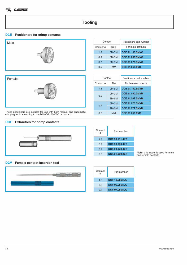
These positioners are suitable for use with both manual and pneumatic crimping tools according to the MIL-C-22520/7-01 standard.
DCE Positioners for crimp contacts
Tooling
Note: this model is used for male and female contacts.
Male
Female
Contact
Contact ø Size
DCE.91.130.5MVC
DCE.91.090.5MVC
DCE.91.070.5MVC
DCE.91.050.0VC
1.3 0M-5M
0.9 0M-5M
0.7 0M-5M
0.5 MM
Contact
Contact ø Size
DCE.91.130.5MVM
DCE.91.090.3MVM
DCE.91.09T.5MVM
DCE.91.070.3MVM
DCE.91.07T.5MVM
DCE.91.050.0VM
0M-5M
0M-3M
TM-5M
0M-3M
TM-5M
MM
1.3
0.9
0.7
0.5
DCF Extractors for crimp contacts
Contactø
DCF.93.131.4LT
DCF.93.090.4LT
DCF.93.070.4LT
DCF.91.050.2LT
Part number
1.3
0.9
0.7
0.5
DCV Female contact insertion tool
Contactø
DCV.13.05M.LA
DCV.09.05M.LA
DCV.07.05M.LA
Part number
1.3
0.9
0.7
Positioners part number
For male contacts
Positioners part number
For female contacts
® ®
www.lemo.com 35
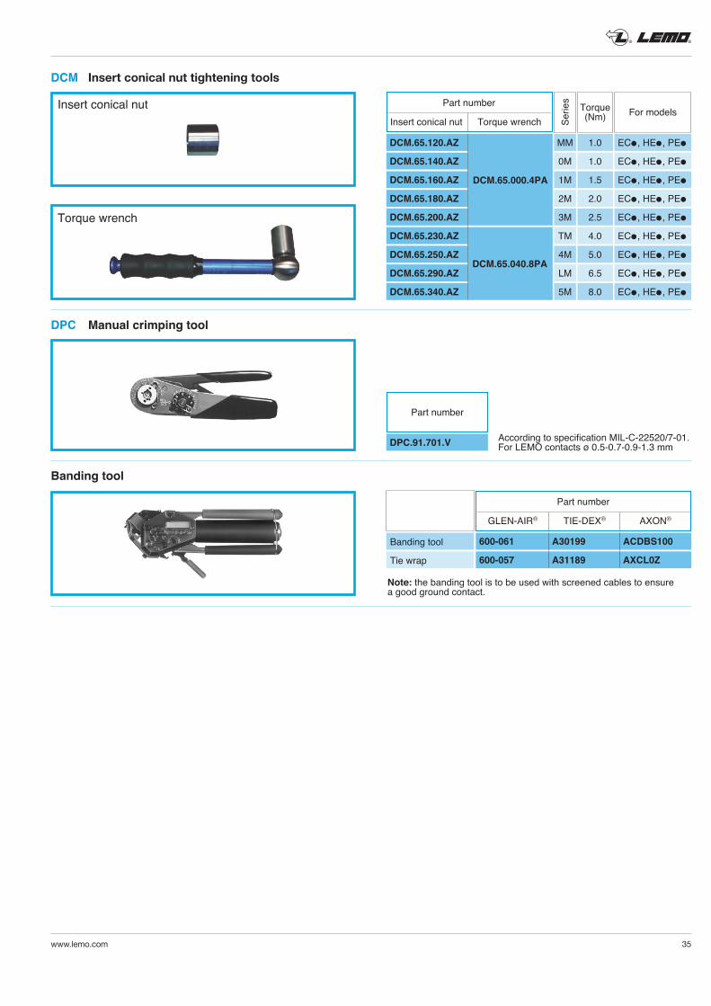
Insert conical nut
Torque wrench
DCM Insert conical nut tightening tools
Torque(Nm)Se
ries
DCM.65.120.AZ
DCM.65.140.AZ
DCM.65.160.AZ
DCM.65.180.AZ
DCM.65.200.AZ
DCM.65.230.AZ
DCM.65.250.AZ
DCM.65.290.AZ
DCM.65.340.AZ
DCM.65.040.8PA
DCM.65.000.4PA
MM
0M
1M
2M
3M
TM
4M
LM
5M
For models
1.0
1.0
1.5
2.0
2.5
4.0
5.0
6.5
8.0
ECl, HEl, PEl
ECl, HEl, PEl
ECl, HEl, PEl
ECl, HEl, PEl
ECl, HEl, PEl
ECl, HEl, PEl
ECl, HEl, PEl
ECl, HEl, PEl
ECl, HEl, PEl
According to specification MIL-C-22520/7-01. For LEMO contacts ø 0.5-0.7-0.9-1.3 mm
Note: the banding tool is to be used with screened cables to ensure a good ground contact.
DPC Manual crimping tool
DPC.91.701.V
Part number
Banding tool
Banding tool
Tie wrap
600-061 A30199 ACDBS100
600-057 A31189 AXCL0Z
Part number
GLEN-AIR® TIE-DEX® AXON®
Part number
Insert conical nut Torque wrench
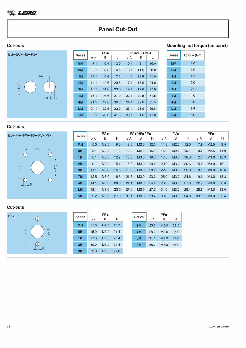
® ®
36 www.lemo.com
ø A
+ 0.
1
0
H +
0.1
0
H + 0.1
0
B
EDl-FAl-FWl-FXl-PVl-PFl
ø A
+ 0.
1
0
H +
0.1
0
B
PBl
Cut-outs
Cut-outs
Series EGl ECl/HElPEl PVl PFl
ø A B H ø A B H ø A B H ø A B H
MM
0M
1M
2M
3M
TM
4M
LM
5M
5.0 M2.5 9.5 9.6 M2.5 12.0 11.8 M2.5 12.0 7.9 M2.5 9.5
5.1 M2.5 11.0 12.3 M2.5 15.1 15.0 M2.5 15.1 10.8 M2.5 11.0
6.1 M3.0 12.9 13.8 M3.0 18.3 17.0 M3.0 18.3 12.5 M3.0 12.9
9.1 M3.0 15.1 16.8 M3.0 20.6 20.0 M3.0 20.6 15.6 M3.0 15.1
11.1 M3.0 16.6 18.8 M3.0 20.6 22.0 M3.0 23.0 18.1 M3.0 16.6
12.5 M3.0 18.3 21.6 M3.0 23.0 25.0 M3.0 24.6 19.9 M3.0 18.3
14.1 M3.0 20.6 24.1 M3.0 24.6 28.0 M3.0 27.0 22.7 M3.0 20.6
18.1 M3.0 23.0 27.6 M3.0 27.0 31.0 M3.0 29.4 25.9 M3.0 23.0
23.2 M3.0 27.0 33.1 M3.0 29.4 38.0 M3.0 34.9 33.1 M3.0 29.4
Series PBl
ø A B H
MM
0M
1M
2M
3M
11.8 M2.5 16.2
15.0 M3.0 21.4
17.0 M3.0 23.4
20.0 M3.0 26.4
22.0 M3.0 29.0
Series PBl
ø A B H
TM
4M
LM
5M
25.0 M3.0 32.5
28.0 M3.0 35.0
31.0 M3.0 38.0
38.0 M3.0 45.0
Panel Cut-Out
Cut-outs Mounting nut torque (on panel)
L mini
B + 0.1 0
ø A
+ 0
.1
0
EGl-ECl-HEl-PEl Series EGl ECl/HElPEl
ø A B L ø A B L
MM
0M
1M
2M
3M
TM
4M
LM
5M
7.1 6.4 12.5 10.1 9.1 16.0
9.1 8.3 14.5 13.1 11.6 20.0
11.1 9.6 17.2 14.1 12.6 21.0
14.1 12.6 20.5 17.1 15.6 24.0
16.1 14.6 23.0 19.1 17.6 27.0
18.1 16.6 27.0 22.1 20.6 31.5
21.1 19.6 30.0 24.1 22.6 35.5
24.1 22.6 32.0 28.1 26.6 36.5
30.1 28.6 41.0 33.1 31.6 41.0
Series Torque (Nm)
MM
0M
1M
2M
3M
TM
4M
LM
5M
1.0
1.0
1.5
2.0
2.5
4.0
5.0
6.5
8.0
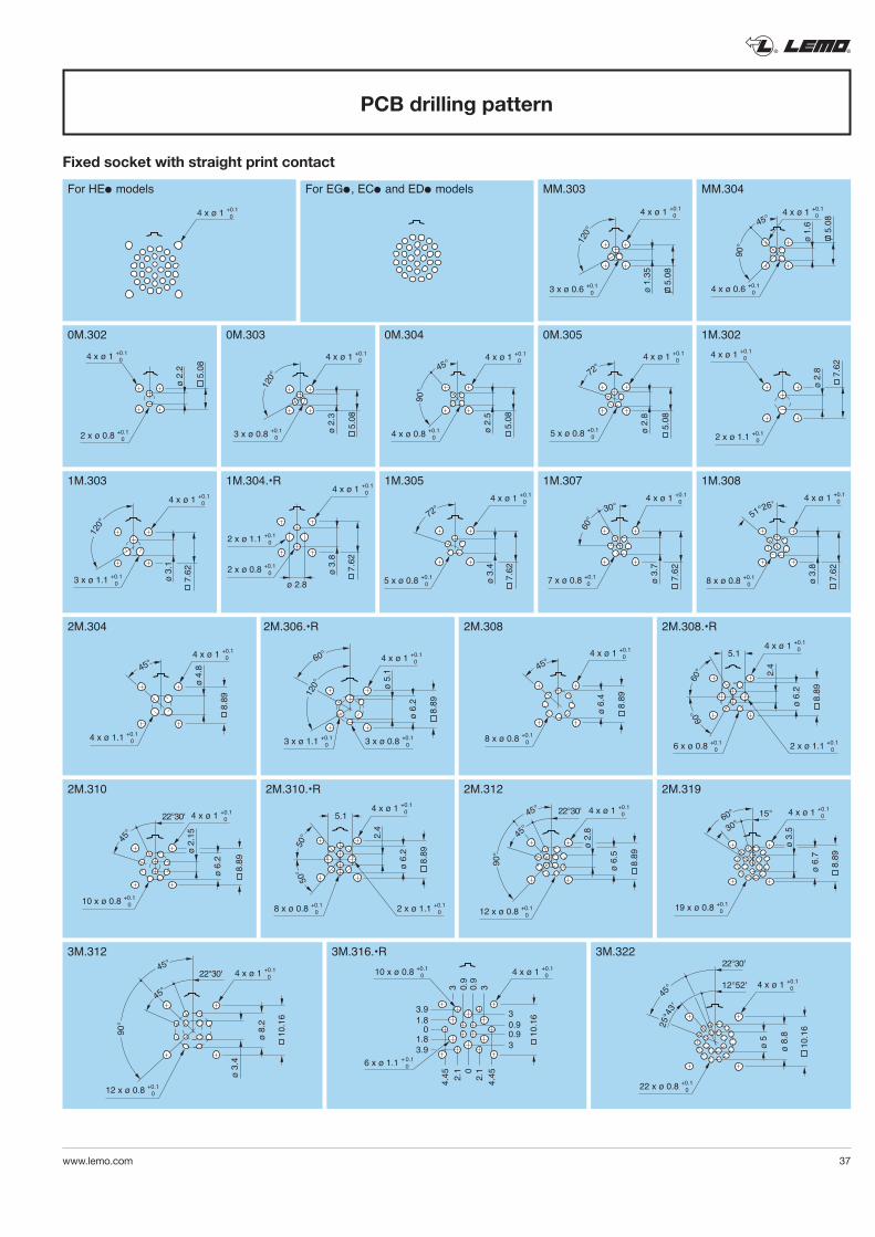
® ®
www.lemo.com 37
4 x ø 1 +0.1 0
For HEl models For EGl, ECl and EDl models
Fixed socket with straight print contact
4 x ø 1 +0.1 0
2 x ø 0.8 +0.1 0
ø 2.
2
5.08
4 x ø 1 +0.1 0
3 x ø 0.8 +0.1 0
ø 2.
3
120°
5.08
4 x ø 1 +0.1 0
4 x ø 0.8 +0.1 0
90°
ø 2.
5
45°
5.08
4 x ø 1 +0.1 0
5 x ø 0.8 +0.1 0
72°
ø 2.
8
5.08
4 x ø 1 +0.1 0
5 x ø 0.8 +0.1 0
72°
ø 3.
4
7.62
4 x ø 1 +0.1 0
2 x ø 1.1 +0.1 0
ø 2.
8 7.62
4 x ø 1 +0.1 0
3 x ø 1.1 +0.1 0 ø
3.1
7.62
120°
4 x ø 1 +0.1 0
2 x ø 0.8 +0.1 0
2 x ø 1.1 +0.1 0
ø 3.
8
ø 2.8
7.62
4 x ø 1 +0.1 0
7 x ø 0.8 +0.1 0 ø
3.7
60°
30°
7.62
ø 3.
8
8 x ø 0.8 +0.1 0
51°26' 4 x ø 1 +0.1 0
7.62
4 x ø 1 +0.1 0
3 x ø 1.1 +0.1 0
ø 6.
2
ø 5.
1
3 x ø 0.8 +0.1 0
120°
60°
8.89
4 x ø 1 +0.1 0
8 x ø 0.8 +0.1 0
ø 6.
4
45°
8.89
4 x ø 1 +0.1 0
6 x ø 0.8 +0.1 0
ø 6.
2
5.1
2.4
2 x ø 1.1 +0.1 0
60°
8.89
60°
4 x ø 1 +0.1 0
8 x ø 0.8 +0.1 0
ø 6.
2
5.1
2.4
2 x ø 1.1 +0.1 0
50°
8.89
50°
4 x ø 1 +0.1 0
10 x ø 0.8 +0.1 0
ø 6.
2
ø 2.
1545°
22°30'
8.89
ø 2.
8
ø 6.
5
12 x ø 0.8 +0.1 0
90°
45°
45° 22°30' 4 x ø 1 +0.1 0
8.89
4 x ø 1 +0.1 0
4 x ø 1.1 +0.1 0
ø 4.
845°
8.89
PCB drilling pattern
4 x ø 1 +0.1 0
3 x ø 0.6 +0.1 0 ø
1.35
120°
5.08
4 x ø 1 +0.1 0
ø 1.
6
4 x ø 0.6 +0.1 0
90°
45°
5.08
0M.302 0M.303 0M.304 0M.305
1M.305
1M.302
1M.303 1M.304.•R 1M.307 1M.308
2M.306.•R 2M.308 2M.308.•R
2M.310.•R2M.310 2M.312
2M.304
MM.303 MM.304
ø 3.
5
ø 6.
7
30°60°
19 x ø 0.8 +0.1 0
15° 4 x ø 1 +0.1 0
8.89
2M.319
90°
45°
45°
12 x ø 0.8 +0.1 0
ø 3.
4
ø 8.
2
22°30' 4 x ø 1 +0.1 0
10.1
6
45°
22 x ø 0.8 +0.1 0
22°30'
ø 5
ø 8.
8
12°52'
25°4
3'
4 x ø 1 +0.1 0
10.1
6
3M.312 3M.322
6 x ø 1.1 + 0.1 0
4 x ø 1 +0.1 010 x ø 0.8 +0.1
0
10.1
6
00.
90.
9
2.1
2.1
3 3
4.45
4.45
0 0.90.9
1.8
1.8
3
3
3.9
3.9
3M.316.•R
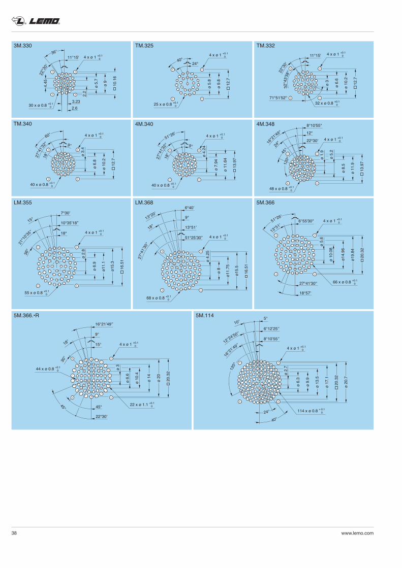
® ®
38 www.lemo.com
36°
30 x ø 0.8 +0.1 0
2.2
ø 5.
7
4.45
2.63.23
11°15'
ø 9
22°3
0'
4 x ø 1 +0.1 0
10.1
6
4 x ø 1 +0.1 015°
22 x ø 1.1 +0.1 0
44 x ø 0.8 +0.1 0
ø 6.
6
ø 10
.4
45° 45°
22°30'
ø 3
ø 14
ø 20
20.3
2
9°
18°
30°
16°21’49’’
4 x ø 1 +0.1 0
114 x ø 0.8 + 0.1 0
5°
6°12’25’’10°
40°
ø 9.
9
ø 6.
3
ø 13
.5
ø 17
.1
8°10’55’’
120°
20.3
2
ø 20
.7
24°
ø 2.
7
12°24’50’’
16°21
’49’’
4 x ø 1 +0.1 0
55 x ø 0.8 +0.1 0
ø 2.
8
10°35’18’’
18°
ø 6.
9
ø11.
1
ø15.
3
16.5
1
7°30’
21°1
0’35’’
36°
15°
4 x ø 1 +0.1 0
68 x ø 0.8 +0.1 0
ø 4.
25
13°51’
51°25’30’’
ø 8
ø11.
75
ø15.
5
16.5
1
9°
6°40’
27°4
1’30’’
18°
13°20’
48 x ø 0.8 +0.1 0
ø 11
.9
24°
ø 5.
2
ø 8.
5
ø 1.
9
22°30'
8°10'55''
12°
45
°
4 x ø 1 +0.1 0
13.9
7
16°21
'49''
120°
25 x ø 0.8 +0.1 0
ø 9.
8
ø 5.
8
24°40°4 x ø 1 +0.1 0
12.7
32 x ø 0.8 +0.1 0
ø 10
.2
ø 3
11°15'
71°51'52''
ø 6.
6
4 x ø 1 +0.1 0
12.7
22°3
0'
32°4
3'38''
40 x ø 0.8 +0.1 0
ø 11
.64
51°26'
18°
9°
ø 4.
24
ø 7.
94
4 x ø 1 +0.1 0
13.9
727°4
1'32''
3M.330
5M.366.•R 5M.114
LM.355 LM.368
TM.325 TM.332
4M.3484M.340
40 x ø 0.8 +0.1 0
ø 10
.2
60°
18°
9°
ø 3.
4
ø 6.
8
4 x ø 1 +0.1 0
12.7
27°4
1'3
2''
TM.340
4 x ø 1 +0.1 06°55'30''
66 x ø 0.8 +0.1 0
ø 5.
6
ø 10
.08
27°41'30''
18°57'
ø14.
96
ø19.
84
13°51'
51°26'
20.3
2
5M.366
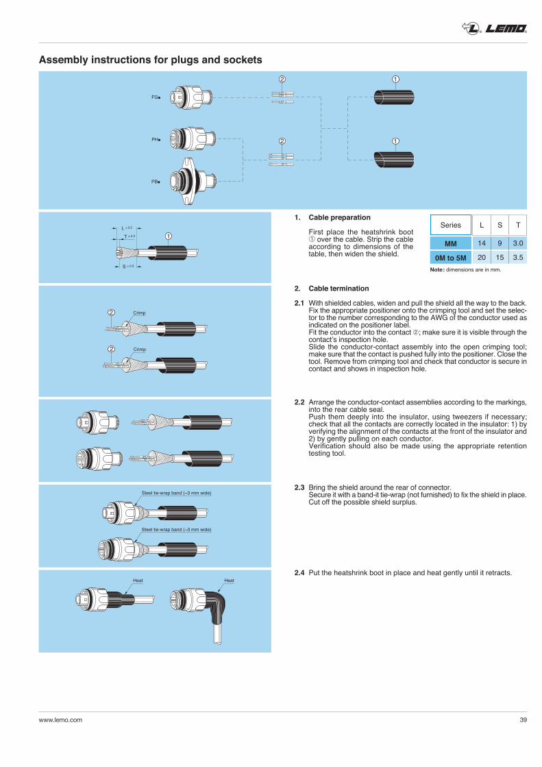
® ®
www.lemo.com 39
Assembly instructions for plugs and sockets
2
2 1
1
FG●
PH●
PB●
1. Cable preparation
First place the heatshrink boot ➀over the cable. Strip the cable accor ding to dimensions of the table, then widen the shield.
2. Cable termination
2.1 With shielded cables, widen and pull the shield all the way to the back. Fix the appropriate positioner onto the crimping tool and set the selec-
tor to the number corresponding to the AWG of the conductor used as indicated on the positioner label.
Fit the conductor into the contact ➁; make sure it is visible through the contact’s inspection hole.
Slide the conductor-contact assembly into the open crimping tool; make sure that the contact is pushed fully into the positioner. Close the tool. Remove from crimping tool and check that conductor is secure in contact and shows in inspection hole.
2.2 Arrange the conductor-contact assemblies according to the markings, into the rear cable seal.
Push them deeply into the insulator, using tweezers if necessary; check that all the contacts are correctly located in the insulator: 1) by verifying the alignment of the contacts at the front of the insulator and 2) by gently pulling on each conductor.
Verification should also be made using the appropriate retention testing tool.
2.3 Bring the shield around the rear of connector. Secure it with a band-it tie-wrap (not furnished) to fix the shield in place. Cut off the possible shield surplus.
2.4 Put the heatshrink boot in place and heat gently until it retracts.
1T ± 0.2
L ± 0.5
S ± 0.5
Crimp2
Crimp2
Steel tie-wrap band (~3 mm wide)
Steel tie-wrap band (~3 mm wide)
Heat Heat
Note: dimensions are in mm.
Series L S T
MM
0M to 5M
14 9 3.0
20 15 3.5
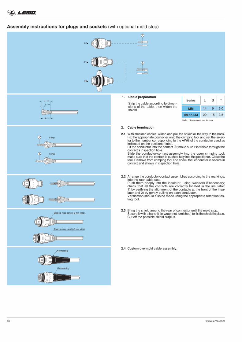
® ®
40 www.lemo.com
Assembly instructions for plugs and sockets (with optional mold stop)
1
1
FG●
PH●
PB●
T ± 0.2
L ± 0.5
S ± 0.5
Crimp1
Crimp1
Steel tie-wrap band (~3 mm wide)
Steel tie-wrap band (~3 mm wide)
Overmolding
Overmolding
1. Cable preparation
Strip the cable accor ding to dimen-sions of the table, then widen the shield.
2. Cable termination
2.1 With shielded cables, widen and pull the shield all the way to the back. Fix the appropriate positioner onto the crimping tool and set the selec-
tor to the number corresponding to the AWG of the conductor used as indicated on the positioner label.
Fit the conductor into the contact ➀; make sure it is visible through the contact’s inspection hole.
Slide the conductor-contact assembly into the open crimping tool; make sure that the contact is pushed fully into the positioner. Close the tool. Remove from crimping tool and check that conductor is secure in contact and shows in inspection hole.
2.2 Arrange the conductor-contact assemblies according to the markings, into the rear cable seal.
Push them deeply into the insulator, using tweezers if necessary; check that all the contacts are correctly located in the insulator: 1) by verifying the alignment of the contacts at the front of the insu-lator and 2) by gently pulling on each conductor.
Verification should also be made using the appropriate retention tes-ting tool.
2.3 Bring the shield around the rear of connector until the mold stop. Secure it with a band-it tie-wrap (not furnished) to fix the shield in place. Cut off the possible shield surplus.
2.4 Custom overmold cable assembly.
Note: dimensions are in mm.
Series L S T
MM
0M to 5M
14 9 3.0
20 15 3.5
® ®
www.lemo.com 41
Data subject to change
No reproduction or use without express permission of editorial or pictorial content, in any manner.LEMO reserve the right at all times to modify and improve specifications without any notification.
PLEASE READ AND FOLLOW ALL INSTUCTIONS CAREFULLY AND CONSULT ALL RELEVENT NATIONAL AND INTERNATIONAL SAFETY REGULATIONS FOR YOUR APPLICATION.IMPROPER HANDLING, CABLE ASSEMBLY, OR WRONG USE OF CONNECTORS CAN RESULT IN HAZARDOUS SITUATIONS.
1. SHOCK AND FIRE HAZARDIncorrect wiring, the use of damaged components, presence of foreign objects (such as metal debris), and / or residue (such as cleaning fluids), can result in short circuits, overheating, and / or risk of electric shock.Mated components should never be disconnected while live as this may result in an exposed electric arc and local overheating, resulting in possible damage to components.
2. HANDLINGConnectors and their components should be visually inspected for damage prior to installation and assembly. Suspect components should be rejected or returned to the factory for verification.Connector assembly and installation should only be carried out by properly trained personnel. Proper tools must be used during installation and / or assembly in order to obtain safe and reliable performance.
3. USEConnectors with exposed contacts should never be live (or on the current supply side of a circuit). Under general conditions voltages above 30 VAC and 42 VDC are considered hazardous and proper measures should be taken to eliminate all risk of transmission of such voltages to any exposed metal part of the connector.
4. TEST AND OPERATING VOLTAGESThe maximum admissible operating voltage depends upon the national or international standards in force for the application in question. Air and creepage distances impact the operating voltage; reference values are indicated in the catalog however these may be influenced by PC board design and / or wiring harnesses.The test voltage indicated in the catalog is 75% of the mean breakdown voltage; the test is applied at 500 V/s and the test duration is 1 minute.
5. CE MARKINGCE marking means that the appliance or equipment bearing it complies with the protection requirements of one or several European safety directives.CE marking applies to complete products or equipment, but not to electromechanical components, such as connectors.
6. PRODUCT IMPROVEMENTSThe LEMO Group reserves the right to modify and improve to our products or specifications without providing prior notification.
Product safety notice
LEMO HEADQUARTERS
SWITZERLANDLEMO SA Chemin des Champs-Courbes 28 - P.O. Box 194 - CH-1024 EcublensTel. (+41 21) 695 16 00 - Fax (+41 21) 695 16 02 - e-mail: [email protected]
LEMO SUBSIDIARIES
LEMO DISTRIBUTORSARGENTINA, AUSTRALIA, BRAZIL, CHILE, COLOMBIA, CZECH REPUBLIC, GREECE, INDIA, ISRAEL, NEW ZEALAND, PERU, POLAND, RUSSIA, SOUTH AFRICA, SOUTH KOREA, TAIWAN, TURKEY, UKRAINE
www.lemo.com
AUSTRIALEMO Elektronik GesmbHLemböckgasse 49/E6-31230 WienTel: (+43 1) 914 23 20 0Fax:(+43 1) 914 23 20 [email protected]
BRAZILLEMO Latin America LtdaAv. José Rocha Bonfim, 214 Salas 224 / 225Condomínio Praça CapitalEd. ChicagoCampinas / SP - Brasil 13080-650Tel: +55 (11) 98689 [email protected]
CANADALEMO Canada Inc44 East Beaver Creek Road, unit 20Richmond Hill, Ontario L4B 1G8Tel: (+1 905) 889 56 78Fax: (+1 905) 889 49 [email protected]
CHINA / HONG KONGLEMO Electronics (Shanghai) Co., Ltd First Floor, Block E,18 Jindian Road, PudongShanghai, China, 201206Tel: (+86 21) 5899 7721Fax: (+86 21) 5899 [email protected]
DENMARKLEMO Denmark A/SNybrovej # 972820 GentofteTel: (+45) 45 20 44 00Fax: (+45) 45 20 44 [email protected]
FRANCELEMO France Sàrl24/28 Avenue Graham BellBâtiment Balthus 4Bussy Saint Georges77607 Marne la Vallée Cedex 3Tel: (+33 1) 60 94 60 94Fax: (+33 1) 60 94 60 [email protected]
GERMANYLEMO Elektronik GmbHHanns-Schwindt-Str. 681829 München Tel: (+49 89) 42 77 03Fax: (+49 89) 420 21 [email protected]
HUNGARYREDEL Elektronika KftNagysándor József u. 6-121201 BudapestTel: (+36 1) 421 47 10Fax: (+36 1) 421 47 [email protected]
ITALYLEMO Italia srlViale Lunigiana 2520125 MilanoTel: (+39 02) 66 71 10 46Fax: (+39 02) 66 71 10 [email protected]
JAPANLEMO Japan Ltd2-7-22, Mita, Minato-ku, Tokyo, 108-0073Tel: (+81 3) 54 46 55 10Fax: (+81 3) 54 46 55 [email protected]
MIDDLE EASTLEMO Middle East Gen. Trad. LLCConcorde Tower 6th Floor, Dubai Media City, P.O. Box 126732Dubai, United Arab EmiratesTel: +971 55 222 36 [email protected]
NETHERLANDS / BELGIUMLEMO Connectors BeneluxDe Trompet 10601967 DA HeemskerkTel. (+31) 251 25 78 20Fax (+31) 251 25 78 [email protected]
NORWAY / ICELANDLEMO Norway A/SSoerumsandvegen 69,1920 SoerumsandTel: (+47) 22 91 70 40Fax: (+47) 22 91 70 [email protected]
SINGAPORELEMO Asia Pte Ltd4 Leng Kee Road, #06-09 SiS Building Singapore 159088Tel: (+65) 6476 0672Fax: (+65) 6474 [email protected]
SPAIN / PORTUGALIBERLEMO SAUBrasil, 45, 08402 GranollersBarcelonaTel: (+34 93) 860 44 20Fax: (+34 93) 879 10 [email protected]
SWEDEN / FINLANDLEMO Nordic ABGunnebogatan 30, Box 8201 163 08 SpångaTel: (+46 8) 635 60 60Fax: (+46 8) 635 60 [email protected]
SWITZERLANDLEMO Verkauf AGGrundstrasse 22 B, 6343 RotkreuzTel: (+41 41) 790 49 [email protected]
UNITED KINGDOMLEMO UK Ltd12-20 North Street, Worthing, West Sussex, BN11 1DUTel: (+44 1903) 23 45 [email protected]
USALEMO USA IncP.O. Box 2408Rohnert Park, CA 94927-2408Tel: (+1 707) 578 88 11(+1 800) 444 53 66Fax:(+1 707) 578 08 [email protected] ©
CA
T.M
M.L
EN.P
0811
- U
pdat
ed M
ay 2
018