Quick Installation Guide - EcoSprize · cabling according to EIA/TIA-568. - Shielding. - CAT-5E or...
2
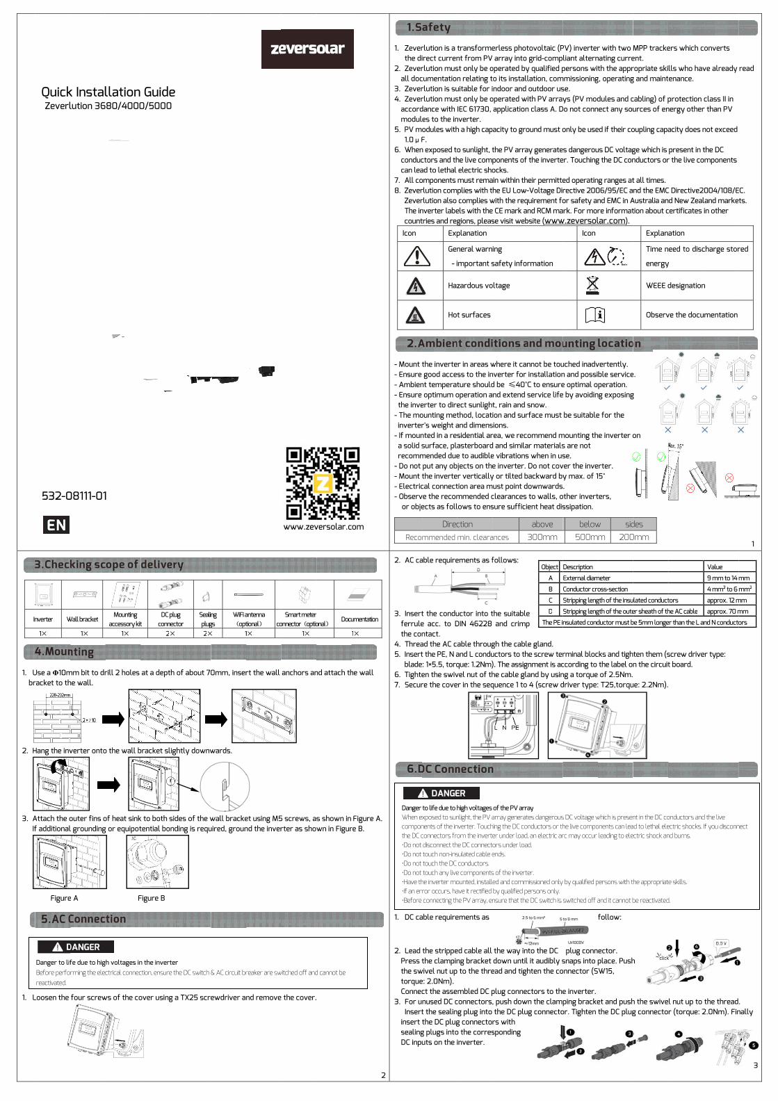
I n 1. U br 2. H 3. A If 1. L Quick Zeverl 532-0 nverter W 1 × Use a Φ10m racket to th Hang the inv Attach the o f additional Figure Loosen the Danger to lif Before perfo reactivated. k Instal lution 36 08111-01 Wall bracket 1 × mm bit to dr he wall. verter onto outer fins o l grounding e A four screw fe due to hig rming the elec llation 80/4000 1 Mounting accessory ki t 1 × rill 2 holes o the wall b of heat sink g or equipot F ws of the co h voltages in ctrical connec Guide 0/5000 t DC pl u connec 2× at a depth bracket slig k to both sid tential bond Figure B over using a n the inverter ction, ensure th ug c tor Seali n plu g 2× of about 70 ghtly downw des of the w ding is requ a TX25 scre r he DC switch & n g g s WiFi a (opt × 1 0mm, inser wards. wall bracke uired, groun ewdriver an & AC circuit br a ntenna t ional ) c o 1 × rt the wall et using M5 nd the inver nd remove reaker are sw Smart mete r o nnecto r ( opti o 1 × anchors an 5 screws, a rter as show the cover. witched off and www.zev r o na l ) Doc u nd attach th s shown in wn in Figur d cannot be versolar.c u mentatio n 1 × he wall Figure A. re B. om 2 1. Zever the di 2. Zever all doc 3. Zever 4. Zever accord modul 5. PV m 1.0μF 6. When conduc can lea 7. All co 8. Zever Zever The in count Icon - Mount t - Ensure - Ambien - Ensure the inve - The mo inverter - If moun a solid s recomm - Do not - Mount t - Electric - Observ or obje Reco 2. AC ca 3. Insert ferrule the con 4. Threa 5. Insert blade 6. Tighte 7. Secur 1. DC ca 2. Lead Press t the sw torque Connec 3. For u Insert insert t sealing DC inpu Danger When e compon the DC c •Do not •Do not •Do not •Do not •Have th •If an er •Before rlution is a t irect curren rlution mus cumentation rlution is su rlution mus dance with es to the in odules with F. n exposed to ctors and th ad to lethal omponents rlution com rlution also nverter labe tries and reg Exp Gen - i Haz Hot the inverte good acce nt temperat optimum o erter to dire ounting met r's weight a nted in a res surface, pla mended due put any ob the inverte cal connect ve the recom ects as foll Diremmended able require t the condu e acc. to D ntact. ad the AC c t the PE, N a : 1×5.5, torq en the swiv re the cove able require the strippe the clampin wivel nut up e: 2.0Nm). ct the asse nused DC c t the sealin the DC plug g plugs into uts on the i to life due to h xposed to sun nents of the i n connectors fro disconnect th touch non-ins touch the DC touch any live he inverter mo ror occurs, ha connecting th transforme nt from PV st only be o n relating t uitable for i st only be o IEC 61730, nverter. h a high cap o sunlight, t he live com electric sho must rema plies with t complies w els with the gions, pleas planation neral warn important s zardous vo t surfaces r in areas w ss to the in ture should operation a ect sunlight thod, locat and dimens sidential ar asterboard e to audible jects on the r vertically tion area m mmended c lows to ens ction min. cleara ements as f uctor into t DIN 46228 able throug and L condu que: 1.2Nm) vel nut of th er in the seq ements as ed cable all ng bracket to the thre mbled DC p connectors g plug into g connecto o the corres inverter. high voltages nlight, the PV a nverter. Touch om the invert he DC connect sulated cable e conductors. e components ounted, install ave it rectified he PV array, en erless phot array into operated by to its install indoor and operated wi application pacity to gro the PV arra ponents of ocks. ain within th he EU Low- with the req e CE mark an se visit web ing safety infor oltage where it can nverter for d be ≤40°C nd extend s t, rain and s ion and sur sions. rea, we reco d and simila e vibrations e inverter. y or tilted b must point d clearances sure suffici ances follows: the suitable and crimp gh the cabl uctors to th ). The assig he cable gla quence 1 to the way in down until ead and tigh plug connec , push dow the DC plu rs with sponding of the PV arra array generat hing the DC co er under load ors under loa ends. s of the inverte ed and comm by qualified p nsure that the tovoltaic (P grid-comp y qualified p lation, com outdoor us ith PV array n class A. D ound must o ay generate the inverte eir permitte -Voltage Di quirement fo nd RCM ma bsite (www rmation nnot be tou installation C to ensure service life snow. rface must ommend m ar materials s when in us Do not cov backward by ownwards to walls, o ent heat dis above 300mm e p e gland. he screw ter nment is ac and by usin 4 (screw d to the DC l it audibly s hten the co ctors to the n the clam g connecto Object A B C D The PE i ay tes dangerous nductors or th , an electric ar d. er. missioned onl y ersons only. e DC switch is PV) inverter liant altern persons wit mmissioning se. ys (PV mod Do not conn only be use es dangerou er. Touching ed operatin rective 200 or safety an ark. For mor w.zeversol Icon uched inadv n and possi e optimal o e by avoidin be suitable mounting th s are not se. ver the inve y max. of 1 . other invert ssipation. below 500m rminal bloc ccording to ng a torque driver type: plug conn snaps into p onnector (S e inverter. ping bracke or. Tighten Description External diam Conductor cro Stripping leng Stripping leng nsulated cond s DC voltage w he live compo rc may occur y by qualified p switched off a r with two nating curre th the appr g, operating dules and c nect any sou ed if their co us DC voltag g the DC con ng ranges at 06/95/EC a nd EMC in A re informat lar.com ). vertently. ble service peration. ng exposing e for the he inverter o erter. 5° ters, w si d m 200 cks and tigh the label on of 2.5Nm. : T25,torqu follow: ector. place. Push W15, et and push the DC plug meter oss-section gth of the insu gth of the oute ductor must b which is presen onents can lea leading to ele persons with t and it cannot b MPP tracke ent. ropriate ski g and maint cabling) of p urces of en oupling capa ge which is nductors or t all times. nd the EMC Australia an tion about c Explan Time n energy WEEE d Observ e. g on des 0mm ten them (s n the circuit ue: 2.2Nm). h h the swive g connecto ulated conduct er sheath of th be 5mm longe nt in the DC co ad to lethal ele ectric shock an he appropriat be reactivated ers which c lls who hav tenance. protection nergy other acity does n present in t r the live co C Directive2 nd New Zeal certificates ation eed to disc y designation ve the docu screw drive t board. l nut up to r (torque: 2 tors he AC cabl e er than the L a onductors and ectric shocks. nd burns. e skills. d. converts ve already class II in r than PV not exceed the DC omponents 004/108/E land marke in other charge stor n umentation er type: the thread 2.0Nm). Fin Value 9 mm to 14 4 mm² to 6 approx. 12 m approx. 70 m and N conducto d the live If you disconn read EC. ts. red . nally mm mm² mm mm ors nect 3 1
Transcript of Quick Installation Guide - EcoSprize · cabling according to EIA/TIA-568. - Shielding. - CAT-5E or...
In
1. Ubr
2. H
3. A
If
1. L
Quick Zeverl
532-0
nverter W
1×
Use a Φ10mracket to th
Hang the inv
Attach the of additional
Figure
Loosen the
Danger to lifBefore perforeactivated.
k Installution 36
08111-01
Wall bracket
1×
mm bit to drhe wall.
verter onto
outer fins ol grounding
e A
four screw
fe due to higrming the elec
llation 80/4000
1
Mounting
accessory kit1×
rill 2 holes
o the wall b
of heat sinkg or equipot
F
ws of the co
h voltages inctrical connec
Guide 0/5000
t DC plu
connec2×
at a depth
bracket slig
k to both sidtential bond
Figure B
over using a
n the inverterction, ensure th
ug ctor
Sealin plug
2×
of about 70
ghtly downw
des of the wding is requ
a TX25 scre
r he DC switch &
ng gs
WiFi a(opt
× 1
0mm, inser
wards.
wall brackeuired, groun
ewdriver an
& AC circuit br
antenna tional)
co
1×
rt the wall
et using M5nd the inver
nd remove
reaker are sw
Smart meter onnector(optio 1×
anchors an
5 screws, arter as show
the cover.
witched off and
www.zev
r onal)
Docu
nd attach th
s shown in wn in Figur
d cannot be
versolar.c
umentation
1×
he wall
Figure A. re B.
om
2
1. Zever the di
2. Zeverall doc
3. Zever4. Zever
accordmodul
5. PV m 1.0μF
6. Whenconduccan lea
7. All co8. Zever
Zever The in count
Icon
- Mount t- Ensure - Ambien- Ensure the inve
- The moinverter
- If mouna solid srecomm
- Do not - Mount t- Electric- Observ or obje
Reco
2. AC ca
3. Insert
ferrulethe con
4. Threa5. Insert
blade6. Tighte7. Secur
1. DC ca
2. Lead Press tthe swtorqueConnec
3. For u Insertinsert tsealingDC inpu
Danger When ecomponthe DC c•Do not •Do not •Do not •Do not •Have th•If an er•Before
rlution is a tirect currenrlution muscumentationrlution is surlution musdance with es to the inodules withF. n exposed toctors and thad to lethal omponents rlution comrlution also nverter labetries and reg
Exp
Gen
- i
Haz
Hot
the inverte good acce
nt temperat optimum oerter to direounting metr's weight anted in a ressurface, plamended due put any obthe invertecal connectve the recomects as foll
Direcmmended
able require
t the condue acc. to Dntact. ad the AC ct the PE, N a: 1×5.5, torqen the swivre the cove
able require
the strippethe clampin
wivel nut upe: 2.0Nm). ct the assenused DC ct the sealinthe DC plugg plugs intouts on the i
to life due to hxposed to sunnents of the inconnectors fro disconnect th touch non-ins touch the DC touch any livehe inverter moror occurs, ha connecting th
transforment from PVst only be on relating tuitable for ist only be oIEC 61730,
nverter. h a high cap
o sunlight, the live com electric shomust remaplies with t complies wels with thegions, pleas
planation
neral warn
important s
zardous vo
t surfaces
r in areas wss to the inture shouldoperation aect sunlightthod, locatand dimenssidential arasterboarde to audiblejects on ther vertically
tion area mmmended clows to ens
ction min. cleara
ements as f
uctor into tDIN 46228
able througand L conduque: 1.2Nm)vel nut of ther in the seq
ements as
ed cable all ng bracket to the thre mbled DC p
connectorsg plug into g connectoo the corresinverter.
high voltages nlight, the PV anverter. Touchom the invert
he DC connectsulated cable e conductors. e componentsounted, installave it rectified he PV array, en
erless phot array into
operated byto its installindoor and
operated wi application
pacity to gro
the PV arraponents of ocks.
ain within thhe EU Low-
with the reqe CE mark anse visit web
ing
safety infor
oltage
where it cannverter for d be ≤40°Cnd extend st, rain and sion and sur
sions. rea, we recod and similae vibrationse inverter.
y or tilted bmust point d
clearances sure suffici
ances
follows:
the suitable and crimp
gh the cabluctors to th). The assighe cable glaquence 1 to
the way in down untilead and tigh
plug connec, push dow the DC plurs with sponding
of the PV arraarray generathing the DC coer under loadors under loaends.
s of the inverteed and comm by qualified pnsure that the
tovoltaic (P grid-compy qualified plation, com outdoor usith PV array
n class A. D
ound must o
ay generate the inverte
eir permitte-Voltage Di
quirement fond RCM ma
bsite (www
rmation
nnot be tou installationC to ensureservice lifesnow. rface must
ommend mar materialss when in usDo not cov
backward byownwards to walls, oent heat dis
above 300mm
e p
e gland. he screw ternment is acand by usin 4 (screw d
to the DC l it audibly shten the co
ctors to then the clamg connecto
Object
A
B
C
D
The PE i
ay tes dangerousnductors or th, an electric ard.
er. missioned only
ersons only. e DC switch is
PV) inverterliant alternpersons wit
mmissioningse. ys (PV mod
Do not conn
only be use
es dangerouer. Touching
ed operatinrective 200or safety an
ark. For morw.zeversol
Icon
uched inadvn and possie optimal oe by avoidin
be suitable
mounting ths are not se.
ver the invey max. of 1.
other invertssipation.
below500m
rminal blocccording to ng a torque driver type:
plug connsnaps into p
onnector (S
e inverter. ping bracke
or. Tighten
Description
External diam
Conductor cro
Stripping leng
Stripping leng
nsulated cond
s DC voltage whe live comporc may occur
y by qualified p
switched off a
r with two nating curreth the appr
g, operating
dules and cnect any sou
ed if their co
us DC voltagg the DC con
ng ranges at06/95/EC and EMC in Are informatlar.com).
vertently. ble serviceperation.
ng exposing
e for the
he inverter o
erter. 5°
ters,
w sidm 200
cks and tigh the label on of 2.5Nm.: T25,torqu
follow:
ector. place. PushW15,
et and pushthe DC plug
meter
oss-section
gth of the insu
gth of the oute
ductor must b
which is presenonents can lealeading to ele
persons with t
and it cannot b
MPP trackeent. ropriate skig and maint
cabling) of purces of en
oupling capa
ge which is nductors or
t all times. nd the EMC
Australia antion about c
Explan
Time n
energy
WEEE d
Observ
e.
g
on
des 0mm
ten them (sn the circuit
ue: 2.2Nm).
h
h the swiveg connecto
ulated conduct
er sheath of th
be 5mm longe
nt in the DC coad to lethal eleectric shock an
he appropriat
be reactivated
ers which c
lls who havtenance.
protection nergy other
acity does n
present in tr the live co
C Directive2nd New Zealcertificates
ation
eed to disc
y
designation
ve the docu
screw drivet board.
l nut up to r (torque: 2
tors
he AC cable
er than the L a
onductors andectric shocks. nd burns.
e skills.
d.
converts
ve already
class II in r than PV
not exceed
the DC omponents
004/108/Eland markein other
charge stor
n
umentation
er type:
the thread2.0Nm). Fin
Value
9 mm to 14
4 mm² to 6
approx. 12 m
approx. 70 m
and N conducto
d the live If you disconn
read
EC. ts.
red
. nally
mm
mm²
mm
mm
ors
nect
3
1
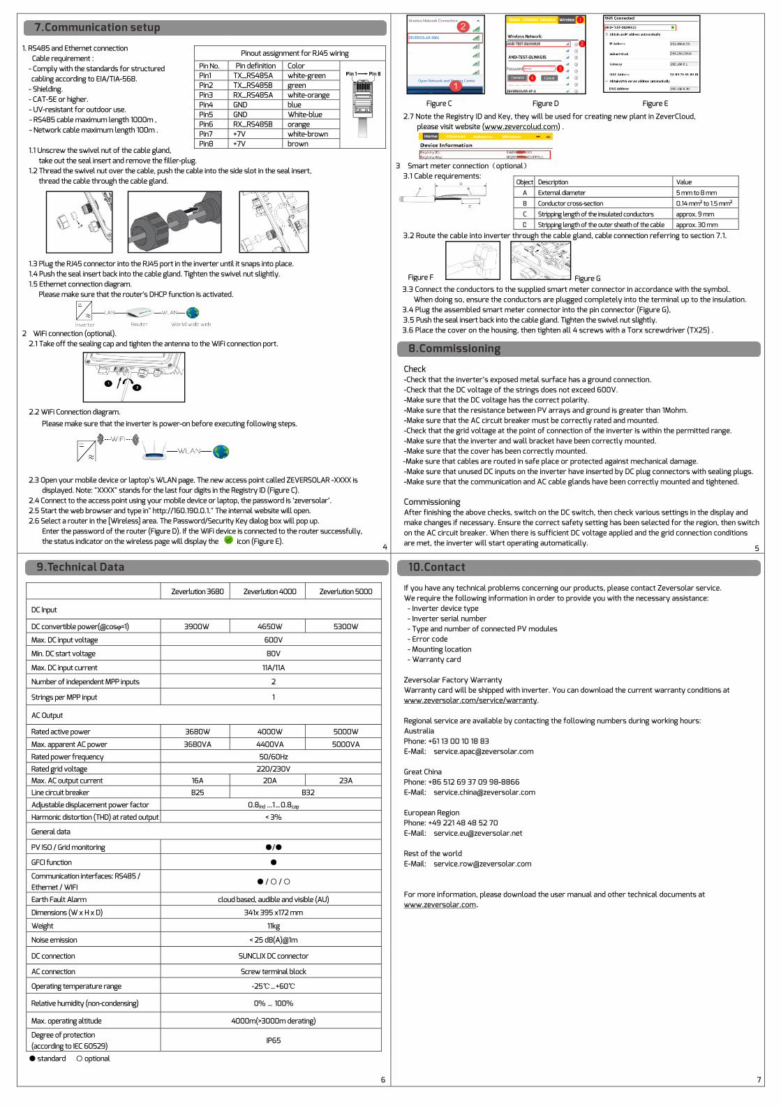
1. RS485 and Ethernet connection Cable requirement : - Comply with the standards for structured cabling according to EIA/TIA-568.
- Shielding. - CAT-5E or higher. - UV-resistant for outdoor use. - RS485 cable maximum length 1000m , - Network cable maximum length 100m .
1.1 Unscrew the swivel nut of the cable gland, take out the seal insert and remove the filler-plug. 1.2 Thread the swivel nut over the cable, push the cable into the side slot in the seal insert, thread the cable through the cable gland.
1.3 Plug the RJ45 connector into the RJ45 port in the inverter until it snaps into place. 1.4 Push the seal insert back into the cable gland. Tighten the swivel nut slightly. 1.5 Ethernet connection diagram. Please make sure that the router's DHCP function is activated.
2 WiFi connection (optional). 2.1 Take off the sealing cap and tighten the antenna to the WiFi connection port.
2.2 WiFi Connection diagram.
Please make sure that the inverter is power-on before executing following steps.
2.3 Open your mobile device or laptop’s WLAN page. The new access point called ZEVERSOLAR -XXXX is displayed. Note: "XXXX" stands for the last four digits in the Registry ID (Figure C). 2.4 Connect to the access point using your mobile device or laptop, the password is ‘zeversolar’. 2.5 Start the web browser and type in" http://160.190.0.1." The internal website will open. 2.6 Select a router in the [Wireless] area. The Password/Security Key dialog box will pop up. Enter the password of the router (Figure D). If the WiFi device is connected to the router successfully, the status indicator on the wireless page will display the icon (Figure E).
Pinout assignment for RJ45 wiring
Pin No. Pin definition Color
Pin1 TX_RS485A white-green Pin2 TX_RS485B green Pin3 RX_RS485A white-orange Pin4 GND blue Pin5 GND White-blue Pin6 RX_RS485B orange Pin7 +7V white-brown Pin8 +7V brown
Figure C Figure D Figure E
2.7 Note the Registry ID and Key, they will be used for creating new plant in ZeverCloud, please visit website (www.zevercolud.com) .
3 Smart meter connection(optional) 3.1 Cable requirements:
3.2 Route the cable into inverter through the cable gland, cable connection referring to section 7.1.
Figure G 3.3 Connect the conductors to the supplied smart meter connector in accordance with the symbol. When doing so, ensure the conductors are plugged completely into the terminal up to the insulation. 3.4 Plug the assembled smart meter connector into the pin connector (Figure G),
3.5 Push the seal insert back into the cable gland. Tighten the swivel nut slightly. 3.6 Place the cover on the housing, then tighten all 4 screws with a Torx screwdriver (TX25) .
Check -Check that the inverter’s exposed metal surface has a ground connection. -Check that the DC voltage of the strings does not exceed 600V. -Make sure that the DC voltage has the correct polarity. -Make sure that the resistance between PV arrays and ground is greater than 1Mohm. -Make sure that the AC circuit breaker must be correctly rated and mounted. -Check that the grid voltage at the point of connection of the inverter is within the permitted range. -Make sure that the inverter and wall bracket have been correctly mounted. -Make sure that the cover has been correctly mounted. -Make sure that cables are routed in safe place or protected against mechanical damage. -Make sure that unused DC inputs on the inverter have inserted by DC plug connectors with sealing plugs. -Make sure that the communication and AC cable glands have been correctly mounted and tightened. Commissioning After finishing the above checks, switch on the DC switch, then check various settings in the display and make changes if necessary. Ensure the correct safety setting has been selected for the region, then switch on the AC circuit breaker. When there is sufficient DC voltage applied and the grid connection conditions are met, the inverter will start operating automatically.
Object Description Value
A External diameter 5 mm to 8 mm
B Conductor cross-section 0.14 mm² to 1.5 mm²
C Stripping length of the insulated conductors approx. 9 mm
D Stripping length of the outer sheath of the cable approx. 30 mm
Zeverlution 3680 Zeverlution 4000 Zeverlution 5000
DC Input
DC convertible power(@cosφ=1) 3900W 4650W 5300W
Max. DC input voltage 600V
Min. DC start voltage 80V
Max. DC input current 11A/11A
Number of independent MPP inputs 2
Strings per MPP input 1
AC Output
Rated active power 3680W 4000W 5000W
Max. apparent AC power 3680VA 4400VA 5000VA
Rated power frequency 50/60Hz
Rated grid voltage 220/230V Max. AC output current 16A 20A 23A
Line circuit breaker B25 B32
Adjustable displacement power factor 0.8Ind ...1…0.8cap
Harmonic distortion (THD) at rated output < 3%
General data
PV ISO / Grid monitoring ●/●
GFCI function ●
Communication interfaces: RS485 / Ethernet / WIFI
● / ○ / ○
Earth Fault Alarm cloud based, audible and visible (AU)
Dimensions (W x H x D) 341x 395 x172 mm
Weight 11kg
Noise emission < 25 dB(A)@1m
DC connection SUNCLIX DC connector
AC connection Screw terminal block
Operating temperature range -25℃…+60℃
Relative humidity (non-condensing) 0% … 100%
Max. operating altitude 4000m(>3000m derating)
Degree of protection (according to IEC 60529)
IP65
● standard ○ optional
If you have any technical problems concerning our products, please contact Zeversolar service. We require the following information in order to provide you with the necessary assistance: - Inverter device type - Inverter serial number - Type and number of connected PV modules - Error code - Mounting location - Warranty card Zeversolar Factory Warranty Warranty card will be shipped with inverter. You can download the current warranty conditions at www.zeversolar.com/service/warranty. Regional service are available by contacting the following numbers during working hours: Australia Phone: +61 13 00 10 18 83 E-Mail: [email protected] Great China Phone: +86 512 69 37 09 98-8866 E-Mail: [email protected] European Region Phone: +49 221 48 48 52 70 E-Mail: [email protected] Rest of the world E-Mail: [email protected] For more information, please download the user manual and other technical documents at www.zeversolar.com.
Figure F
7
4
6
5