GT-RK1 - GEMS NAVen.gemsnav.com/upload/file/20160816/1103-GT-RK1_en.pdfGT‐RK1 is a repeater ......
16
Doc.No.1103 Rev.013 2016-08-16 Tel: +86-755-29644311 Fax: +86-755-29644383-816 Email: [email protected] GEMS NAVIGATION LIMITED Room 301,Hua Chuang Da Building, Cuizhu Rd,46 District, Bao’an, Shenzhen, China. GT-RK1 GPS signal indoor coverage system Installation and user guide WWW.GEMSNAV.COM GEMS NAVIGATION LIMITED
-
Upload
trinhkhanh -
Category
Documents
-
view
219 -
download
1
Transcript of GT-RK1 - GEMS NAVen.gemsnav.com/upload/file/20160816/1103-GT-RK1_en.pdfGT‐RK1 is a repeater ......
Doc.No.1103 Rev.013 2016-08-16
Tel: +86-755-29644311 Fax: +86-755-29644383-816 Email: [email protected] GEMS NAVIGATION LIMITED Room301,HuaChuangDaBuilding,CuizhuRd,46District,Bao’an,Shenzhen,China.
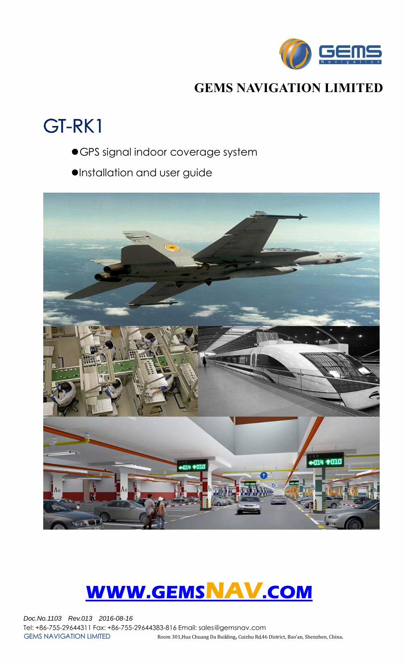
GT-RK1 GPS signal indoor coverage system
Installation and user guide
WWW.GEMSNAV.COM
GEMS NAVIGATION LIMITED
Doc.No.1103 Rev.013 2016-08-16
Tel: +86-755-29644311 Fax: +86-755-29644383-816 Email: [email protected] Web: www.gemsnav.com Page 2 / 16
GT-RK1 System signal: GPS L1(1575MHz);
This is single point solution, covers 5-20 meters at radius(by increasing the amplifier according to methods and under field conditions, building height and other certain conditions reach a radius of 20 meters).
Note: Single point means one antenna be used to transmitting GPS signal.
Doc.No.1103 Rev.013 2016-08-16
Tel: +86-755-29644311 Fax: +86-755-29644383-816 Email: [email protected] Web: www.gemsnav.com Page 3 / 16
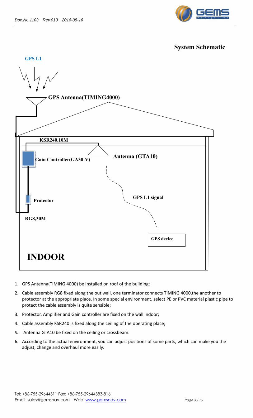
System Schematic
l 1. GPS Antenna(TIMING 4000) be installed on roof of the building;
2. Cable assembly RG8 fixed along the out wall, one terminator connects TIMING 4000,the another to protector at the appropriate place. In some special environment, select PE or PVC material plastic pipe to protect the cable assembly is quite sensible;
3. Protector, Amplifier and Gain controller are fixed on the wall indoor;
4. Cable assembly KSR240 is fixed along the ceiling of the operating place;
5. Antenna GTA10 be fixed on the ceiling or crossbeam.
6. According to the actual environment, you can adjust positions of some parts, which can make you the adjust, change and overhaul more easily.
GPS L1
GPS Antenna(TIMING4000)
Antenna (GTA10)Gain Controller(GA30-V)
KSR240,10M
Protector
INDOOR
GPS device
GPS L1 signal
RG8,30M
Doc.No.1103 Rev.013 2016-08-16
Tel: +86-755-29644311 Fax: +86-755-29644383-816 Email: [email protected] Web: www.gemsnav.com Page 4 / 16
Quality Commitment
All products have been strictly inspected, all are qualified products.
We promise one‐year guaranty and 5‐year available.
Under warranty, products gone wrong which be identified not be human factor, can be replaced free or repaired. Freight be charged by GEMS.
Return Policy
Our product and its packaging have LOGO and Serial‐number, you should not tear up them, as we will depend on them to deal with the return product.
We haven’t recruit agencies, sales and after service be took charged by GEMS. Please pay attention.
Service phone:86-755-29644311or email to:[email protected], We will response in 24 hours.
Doc.No.1103 Rev.013 2016-08-16
Tel: +86-755-29644311 Fax: +86-755-29644383-816 Email: [email protected] Web: www.gemsnav.com Page 5 / 16
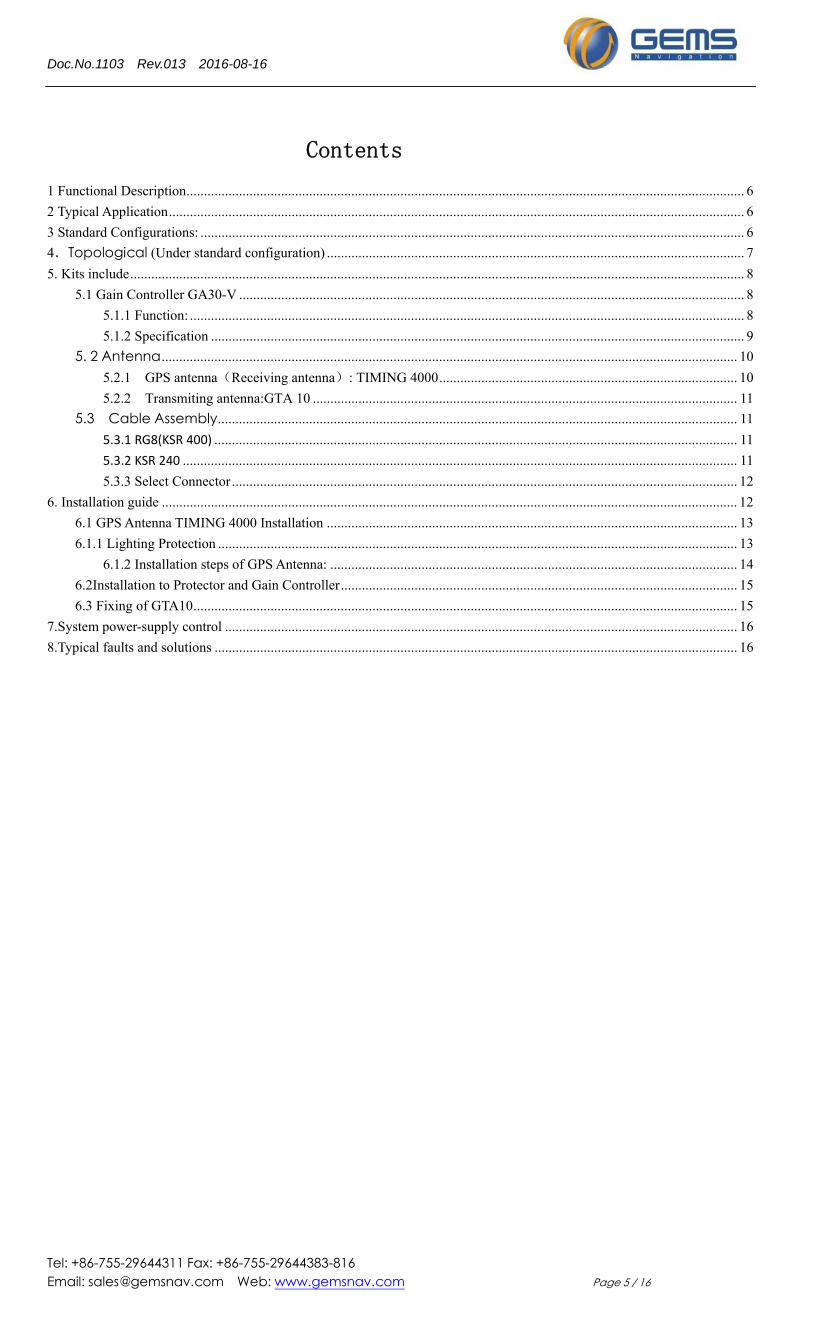
Contents
1 Functional Description ............................................................................................................................................................... 6
2 Typical Application .................................................................................................................................................................... 6
3 Standard Configurations: ........................................................................................................................................................... 6
4.Topological (Under standard configuration) ....................................................................................................................... 7
5. Kits include ............................................................................................................................................................................... 8
5.1 Gain Controller GA30-V ................................................................................................................................................ 8
5.1.1 Function: .............................................................................................................................................................. 8
5.1.2 Specification ........................................................................................................................................................ 9
5. 2 Antenna .................................................................................................................................................................... 10
5.2.1 GPS antenna(Receiving antenna): TIMING 4000 ..................................................................................... 10
5.2.2 Transmiting antenna:GTA 10 ......................................................................................................................... 11
5.3 Cable Assembly .................................................................................................................................................... 11
5.3.1 RG8(KSR 400) ..................................................................................................................................................... 11
5.3.2 KSR 240 .............................................................................................................................................................. 11
5.3.3 Select Connector ................................................................................................................................................ 12
6. Installation guide .................................................................................................................................................................... 12
6.1 GPS Antenna TIMING 4000 Installation ..................................................................................................................... 13
6.1.1 Lighting Protection .................................................................................................................................................... 13
6.1.2 Installation steps of GPS Antenna: .................................................................................................................... 14
6.2Installation to Protector and Gain Controller ................................................................................................................. 15
6.3 Fixing of GTA10 ........................................................................................................................................................... 15
7.System power-supply control .................................................................................................................................................. 16
8.Typical faults and solutions ..................................................................................................................................................... 16
Doc.No.1103 Rev.013 2016-08-16
Tel: +86-755-29644311 Fax: +86-755-29644383-816 Email: [email protected] Web: www.gemsnav.com Page 6 / 16
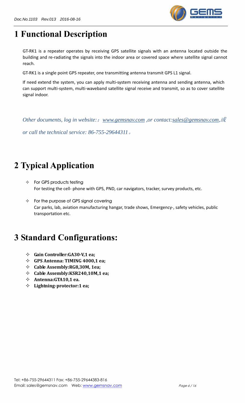
1 Functional Description
GT‐RK1 is a repeater operates by receiving GPS satellite signals with an antenna located outside the
building and re‐radiating the signals into the indoor area or covered space where satellite signal cannot
reach.
GT‐RK1 is a single point GPS repeater, one transmitting antenna transmit GPS L1 signal.
If need extend the system, you can apply multi‐system receiving antenna and sending antenna, which
can support multi‐system, multi‐waveband satellite signal receive and transmit, so as to cover satellite
signal indoor.
Other documents, log in website::www.gemsnav.com ,or contact:[email protected],或
or call the technical service: 86-755-29644311。
2 Typical Application
For GPS products testing For testing the cell‐ phone with GPS, PND, car navigators, tracker, survey products, etc.
For the purpose of GPS signal covering Car parks, lab, aviation manufacturing hangar, trade shows, Emergency‐, safety vehicles, public
transportation etc.
3 Standard Configurations:
GainController:GA30‐V,1ea; GPSAntenna:TIMING4000,1ea; CableAssembly:RG8,30M,1ea; CableAssembly:KSR240,10M,1ea; Antenna:GTA10,1ea. Lightning‐protector:1ea;
Doc.No.1103 Rev.013 2016-08-16
Tel: +86-755-29644311 Fax: +86-755-29644383-816 Email: [email protected] Web: www.gemsnav.com Page 7 / 16
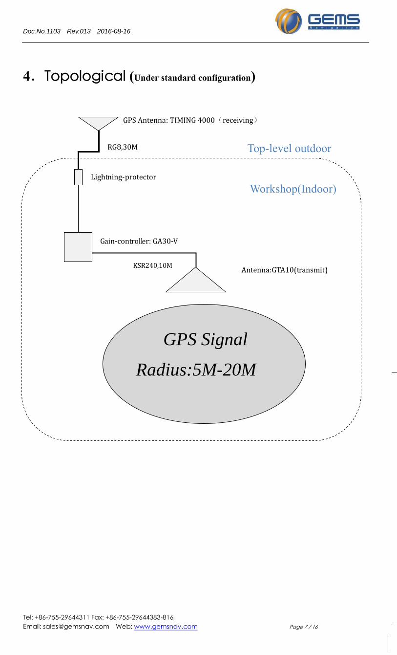
4.Topological (Under standard configuration)
GPS Signal
Radius:5M-20M
GPSAntenna:TIMING4000(receiving)
Lightning‐protector
Gain‐controller:GA30‐V
Antenna:GTA10(transmit)
RG8,30M
KSR240,10M
Top-level outdoor
Workshop(Indoor)
Doc.No.1103 Rev.013 2016-08-16
Tel: +86-755-29644311 Fax: +86-755-29644383-816 Email: [email protected] Web: www.gemsnav.com Page 8 / 16
5. Kits include
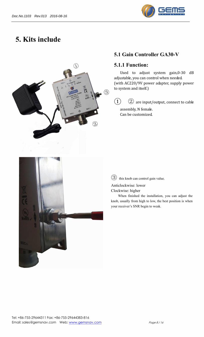
5.1 Gain Controller GA30-V
5.1.1 Function: Used to adjust system gain,0‐30 dB
adjustable,youcancontrolwhenneeded.(withAC220/9Vpoweradapter,supplypowertosystemanditself.)
① ② areinput/output,connecttocable
assembly,Nfemale.Canbecustomized.
③ this knob can control gain value.
Anticlockwise: lower Clockwise: higher
When finished the installation, you can adjust the
knob, usually from high to low, the best position is when
your receiver’s SNR begin to weak.
Doc.No.1103 Rev.013 2016-08-16
Tel: +86-755-29644311 Fax: +86-755-29644383-816 Email: [email protected] Web: www.gemsnav.com Page 9 / 16
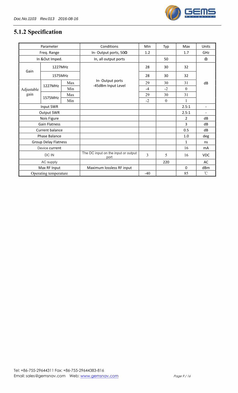
5.1.2 Specification
Parameter Conditions Min Typ Max Units
Freq. Range In‐ Output ports, 50Ω 1.2 1.7 GHz
In &Out Imped. In, all output ports 50 Ω
Gain 1227MHz
In‐ Output ports ‐45dBm Input Level
28 30 32
dB
1575MHz 28 30 32
Adjustable gain
1227MHz Max 29 30 31
Min -4 -2 0
1575MHz Max 29 30 31
Min -2 0 1
Input SWR 2.5:1 ‐
Output SWR 2.5:1 ‐
Nois Figure 2 dB
Gain Flatness 3 dB
Current balance 0.5 dB
Phase Balance 1.0 deg
Group Delay Flatness 1 ns
Device current 16 mA
DC IN The DC input on the input or output port 3 5 16 VDC
AC supply 220 AC
Max RF Input Maximum lossless RF input 0 dBm
Operating temperature -40 85 ℃
Doc.No.1103 Rev.013 2016-08-16
Tel: +86-755-29644311 Fax: +86-755-29644383-816 Email: [email protected] Web: www.gemsnav.com Page 10 / 16
5. 2 Antenna
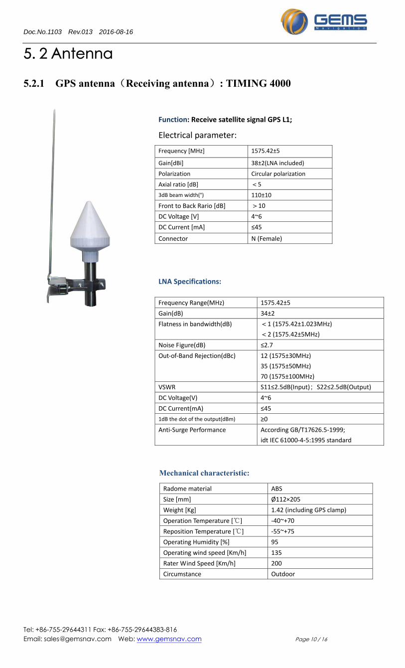
5.2.1 GPS antenna(Receiving antenna): TIMING 4000
Mechanical characteristic:
Radome material ABS
Size [mm] Ø112×205
Weight [Kg] 1.42 (including GPS clamp)
Operation Temperature [℃] ‐40~+70
Reposition Temperature [℃] ‐55~+75
Operating Humidity [%] 95
Operating wind speed [Km/h] 135
Rater Wind Speed [Km/h] 200
Circumstance Outdoor
Function: Receive satellite signal GPS L1;
Electrical parameter:
Frequency [MHz] 1575.42±5
Gain[dBi] 38±2(LNA included)
Polarization Circular polarization
Axial ratio [dB] <5
3dB beam width(°) 110±10
Front to Back Rario [dB] >10
DC Voltage [V] 4~6
DC Current [mA] ≤45
Connector N (Female)
Frequency Range(MHz) 1575.42±5
Gain(dB) 34±2
Flatness in bandwidth(dB) <1 (1575.42±1.023MHz)
<2 (1575.42±5MHz)
Noise Figure(dB) ≤2.7
Out‐of‐Band Rejection(dBc) 12 (1575±30MHz)
35 (1575±50MHz)
70 (1575±100MHz)
VSWR S11≤2.5dB(Input);S22≤2.5dB(Output)
DC Voltage(V) 4~6
DC Current(mA) ≤45
1dB the dot of the output(dBm) ≥0
Anti‐Surge Performance According GB/T17626.5‐1999;
idt IEC 61000‐4‐5:1995 standard
LNA Specifications:
Doc.No.1103 Rev.013 2016-08-16
Tel: +86-755-29644311 Fax: +86-755-29644383-816 Email: [email protected] Web: www.gemsnav.com Page 11 / 16
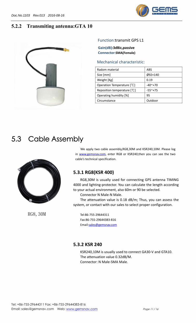
5.2.2 Transmiting antenna:GTA 10
Function:transmit GPS L1
Gain(dB):3dBic,passive
Connector:SMA(Female)
5.3 Cable Assembly
5.3.1 RG8(KSR 400)
RG8,30M is usually used for connecting GPS antenna TIMING
4000 and lighting‐protector. You can calculate the length according
to your actual environment, also 60m or 90 be selected.
Connector N Male‐N Male.
The attenuation value is 0.18 dB/m; Thus, you can assess the
system, or contact with our sales to select proper configuration.
Tel:86‐755‐29644311
Fax:86‐755‐29644383‐816
Email:[email protected]
Mechanical characteristic:
Radom material ABS
Size [mm] Ø92×140
Weight [Kg] 0.19
Operation Temperature [℃] ‐40~+70
Reposition temperature [℃] ‐55~+75
Operating humidity [%] 95
Circumstance Outdoor
We apply two cable assembly,RG8,30M and KSR240,10M. Please log
in www.gemsnav.com, enter RG8 or KSR240,then you can see the two
cable’s technical specification.
RG8,30M
5.3.2 KSR 240
KSR240,10M is usually used to connect GA30‐V and GTA10.
The attenuation value 0.32dB/M.
Connector: N Male‐SMA Male.
Doc.No.1103 Rev.013 2016-08-16
Tel: +86-755-29644311 Fax: +86-755-29644383-816 Email: [email protected] Web: www.gemsnav.com Page 12 / 16
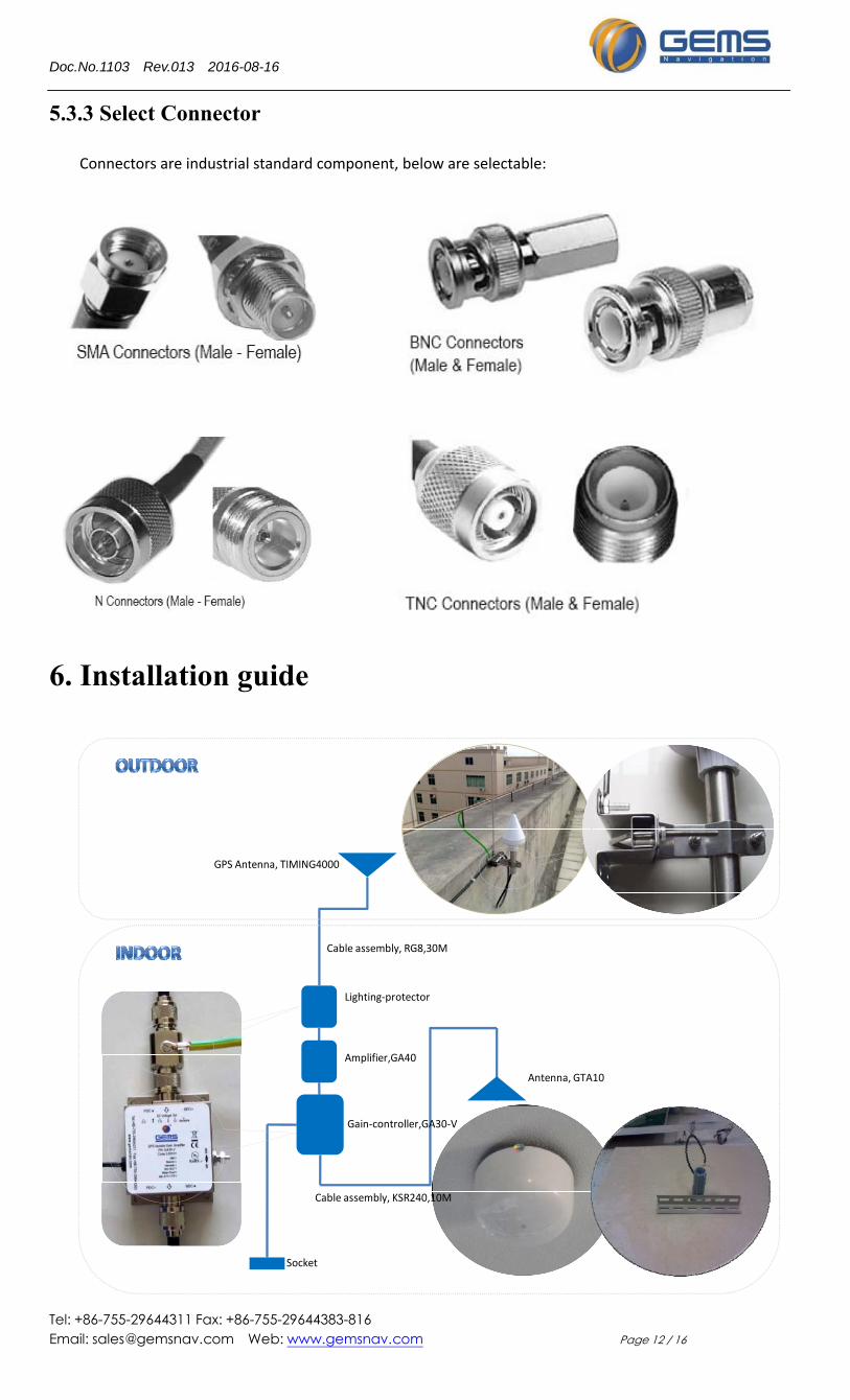
5.3.3 Select Connector
Connectors are industrial standard component, below are selectable:
6. Installation guide
Lighting‐protector
Gain‐controller,GA30‐V
GPS Antenna, TIMING4000
Antenna, GTA10
Socket
Cable assembly, RG8,30M
Cable assembly, KSR240,10M
Amplifier,GA40
Doc.No.1103 Rev.013 2016-08-16
Tel: +86-755-29644311 Fax: +86-755-29644383-816 Email: [email protected] Web: www.gemsnav.com Page 13 / 16
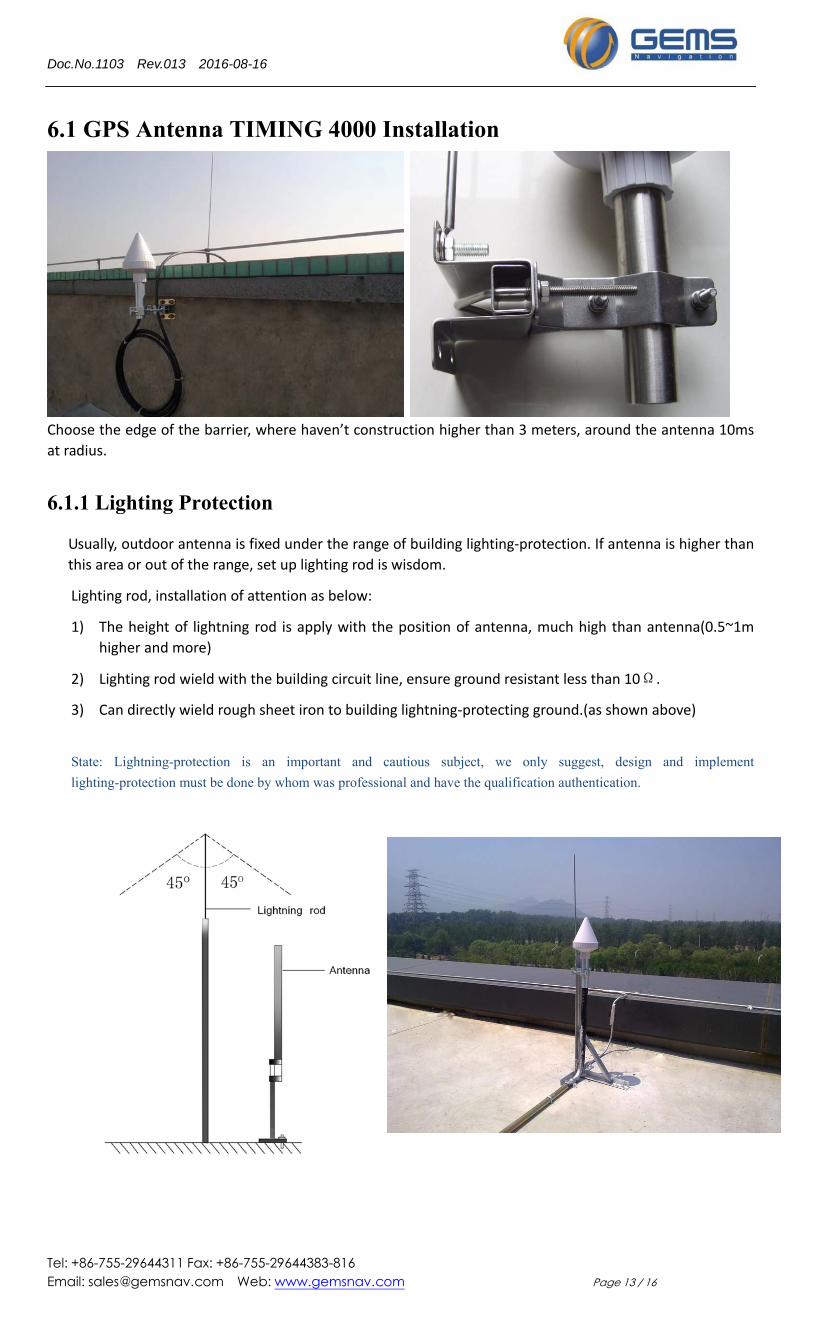
6.1 GPS Antenna TIMING 4000 Installation
Choose the edge of the barrier, where haven’t construction higher than 3 meters, around the antenna 10ms
at radius.
6.1.1 Lighting Protection
Usually, outdoor antenna is fixed under the range of building lighting‐protection. If antenna is higher than
this area or out of the range, set up lighting rod is wisdom.
Lighting rod, installation of attention as below:
1) The height of lightning rod is apply with the position of antenna, much high than antenna(0.5~1m
higher and more)
2) Lighting rod wield with the building circuit line, ensure ground resistant less than 10Ω.
3) Can directly wield rough sheet iron to building lightning‐protecting ground.(as shown above)
State: Lightning-protection is an important and cautious subject, we only suggest, design and implement
lighting-protection must be done by whom was professional and have the qualification authentication.
Doc.No.1103 Rev.013 2016-08-16
Tel: +86-755-29644311 Fax: +86-755-29644383-816 Email: [email protected] Web: www.gemsnav.com Page 14 / 16
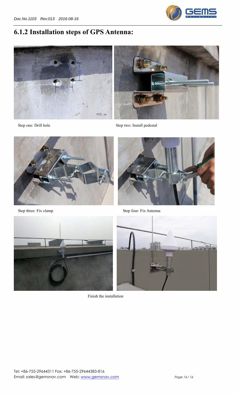
6.1.2 Installation steps of GPS Antenna:
Step one: Drill hole Step two: Install pedestal
Step three: Fix clamp Step four: Fix Antenna
Finish the installation
Doc.No.1103 Rev.013 2016-08-16
Tel: +86-755-29644311 Fax: +86-755-29644383-816 Email: [email protected] Web: www.gemsnav.com Page 15 / 16
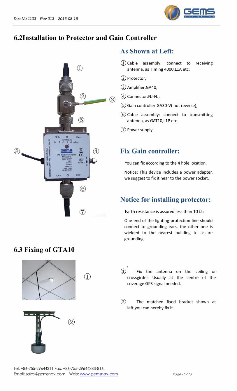
6.2Installation to Protector and Gain Controller
6.3 Fixing of GTA10
As Shown at Left:
① Cable assembly: connect to receiving
antenna, as Timing 4000,L1A etc;
② Protector;
③ Amplifier:GA40;
④ Connector:NJ‐NJ;
⑤ Gain controller:GA30‐V( not reverse);
⑥ Cable assembly: connect to transmitting
antenna, as GAT10,L1P etc.
⑦ Power supply.
Fix Gain controller:
You can fix according to the 4 hole location.
Notice: This device includes a power adapter,
we suggest to fix it near to the power socket.
Notice for installing protector:
Earth resistance is assured less than 10Ω;
One end of the lighting‐protection line should
connect to grounding ears, the other one is
wielded to the nearest building to assure
grounding.
,
�① Fix the antenna on the ceiling or
crossgirder. Usually at the centre of the
coverage GPS signal needed.
�② The matched fixed bracket shown at
left,you can hereby fix it.
①
②
Doc.No.1103 Rev.013 2016-08-16
Tel: +86-755-29644311 Fax: +86-755-29644383-816 Email: [email protected] Web: www.gemsnav.com Page 16 / 16
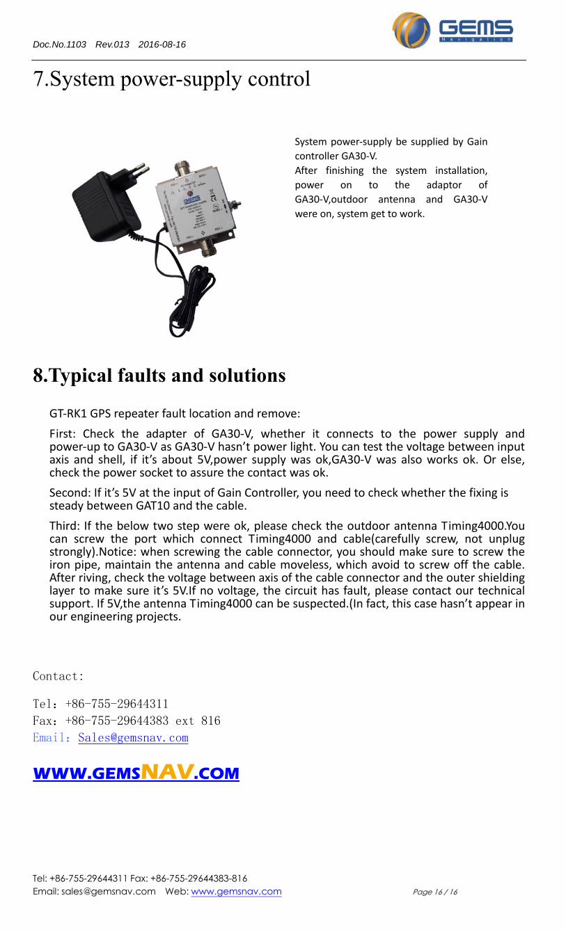
7.System power-supply control
8.Typical faults and solutions
GT‐RK1 GPS repeater fault location and remove:
First: Check the adapter of GA30‐V, whether it connects to the power supply and power‐up to GA30‐V as GA30‐V hasn’t power light. You can test the voltage between input axis and shell, if it’s about 5V,power supply was ok,GA30‐V was also works ok. Or else, check the power socket to assure the contact was ok.
Second: If it’s 5V at the input of Gain Controller, you need to check whether the fixing is steady between GAT10 and the cable.
Third: If the below two step were ok, please check the outdoor antenna Timing4000.You can screw the port which connect Timing4000 and cable(carefully screw, not unplug strongly).Notice: when screwing the cable connector, you should make sure to screw the iron pipe, maintain the antenna and cable moveless, which avoid to screw off the cable. After riving, check the voltage between axis of the cable connector and the outer shielding layer to make sure it’s 5V.If no voltage, the circuit has fault, please contact our technical support. If 5V,the antenna Timing4000 can be suspected.(In fact, this case hasn’t appear in our engineering projects.
Contact:
Tel:+86-755-29644311
Fax:+86-755-29644383 ext 816
Email:[email protected]
WWW.GEMSNAV.COM
System power‐supply be supplied by Gain
controller GA30‐V.
After finishing the system installation,
power on to the adaptor of
GA30‐V,outdoor antenna and GA30‐V
were on, system get to work.


![INDEX [librairie.vetbooks.fr]...INDEX Note: page numbers in italics refer to fi gures, those in bold refer to tables.AB blood group typing 715–17, 1102, 1103 abdominal artery aneurysms](https://static.fdocument.org/doc/165x107/5e6849c121f76b3fda6af5c7/index-index-note-page-numbers-in-italics-refer-to-i-gures-those-in-bold.jpg)