Física de Altas Densidades de Energía en Fusión … · Física de Altas Densidades de Energía...
48
Física de Altas Densidades de Energía en Fusión Inercial Enrique Henestroza Lawrence Berkeley National Laboratory presentado el 4 de Abril de 2008 en el Centro Atómico Constituyentes Prov. Buenos Aires - Argentina
-
Upload
trinhkhanh -
Category
Documents
-
view
219 -
download
0
Transcript of Física de Altas Densidades de Energía en Fusión … · Física de Altas Densidades de Energía...
Física de Altas Densidades de Energía en Fusión Inercial
Enrique HenestrozaLawrence Berkeley National Laboratory
presentado el 4 de Abril de 2008 en el
Centro Atómico Constituyentes
Prov. Buenos Aires - Argentina
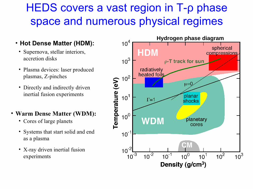
HEDS covers a vast region in T-ρ phase space and numerous physical regimes
• Hot Dense Matter (HDM):• Supernova, stellar interiors,
accretion disks
• Plasma devices: laser produced plasmas, Z-pinches
• Directly and indirectly driven inertial fusion experiments
• Warm Dense Matter (WDM):• Cores of large planets
• Systems that start solid and end as a plasma
• X-ray driven inertial fusion experiments
HED
WDM
Hydrogen phase diagram

High Energy Density Matter occurs widely
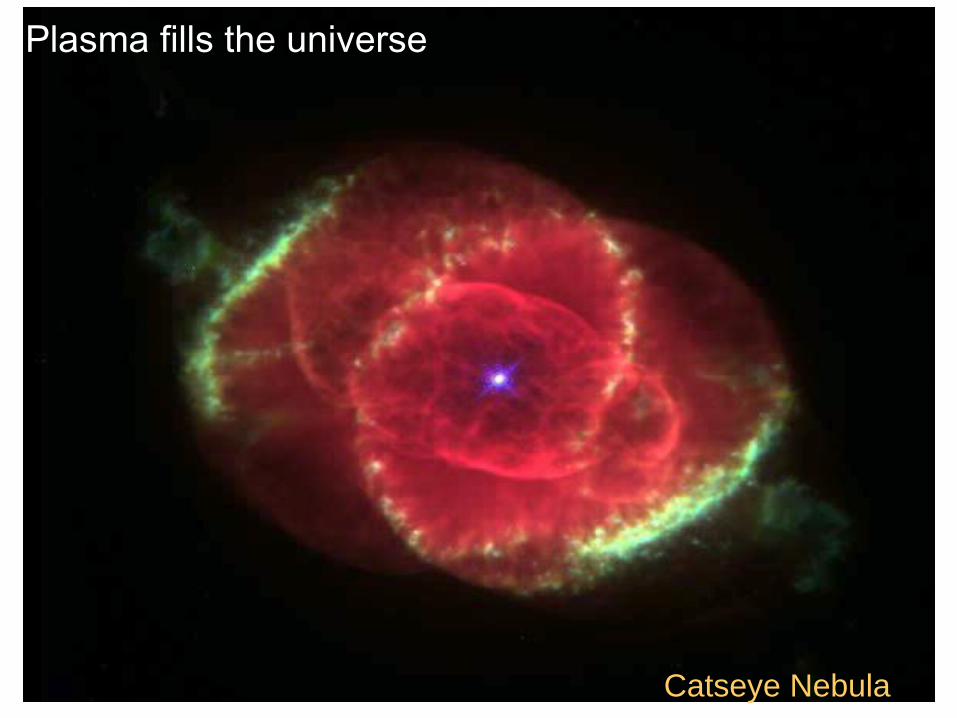
Plasma fills the universe
Catseye Nebula
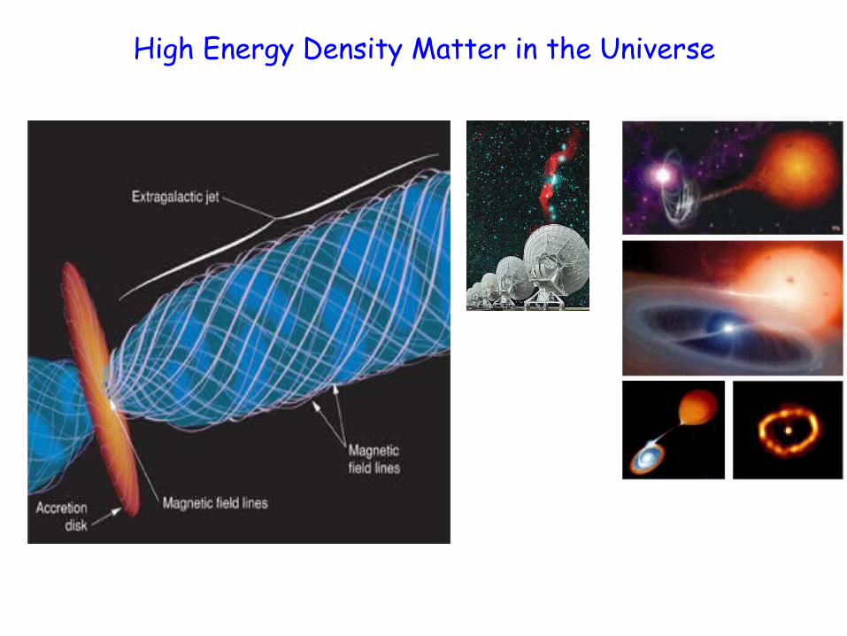
High Energy Density Matter in the Universe
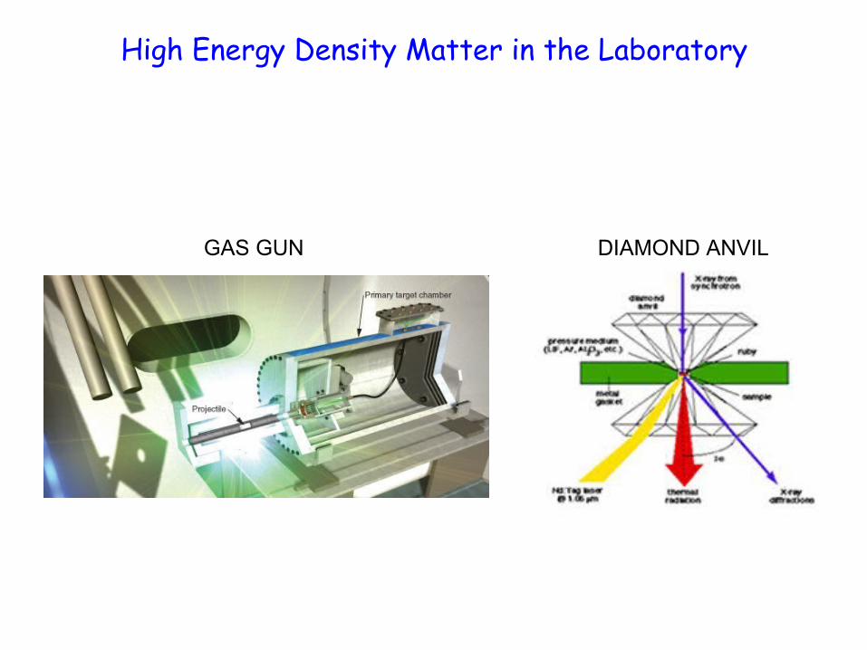
High Energy Density Matter in the Laboratory
GAS GUN DIAMOND ANVIL
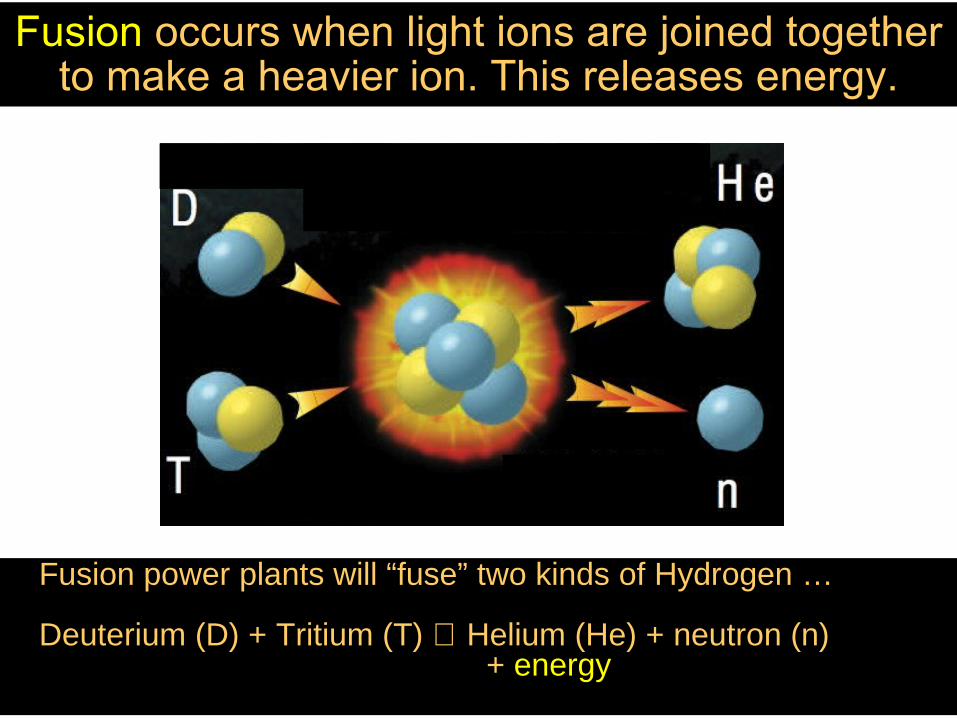
Fusion occurs when light ions are joined together to make a heavier ion. This releases energy.
Fusion power plants will “fuse” two kinds of Hydrogen …
Deuterium (D) + Tritium (T) ⇒ Helium (He) + neutron (n) + energy
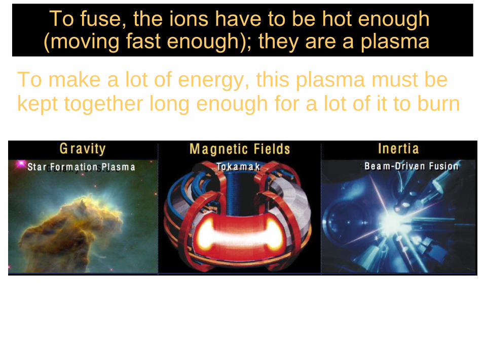
To fuse, the ions have to be hot enough (moving fast enough); they are a plasma
To make a lot of energy, this plasma must be kept together long enough for a lot of it to burn
Vay - 4/25/06 9
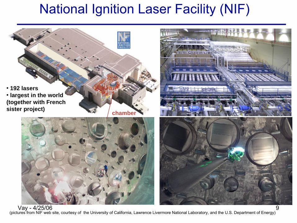
National Ignition Laser Facility (NIF)
• 192 lasers • largest in the world (together with French sister project)
chamber
(pictures from NIF web site, courtesy of the University of California, Lawrence Livermore National Laboratory, and the U.S. Department of Energy)
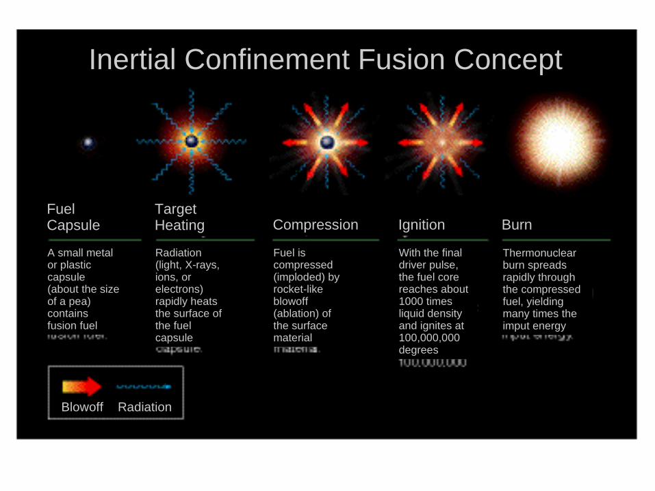
Blowoff Radiation
FuelCapsule
TargetHeating Compression BurnIgnition
A small metalor plasticcapsule(about the size of a pea) contains fusion fuel
Radiation (light, X-rays, ions, or electrons) rapidly heats the surface of the fuel capsule
Fuel is compressed (imploded) by rocket-like blowoff (ablation) of the surface material
With the final driver pulse, the fuel core reaches about 1000 times liquid density and ignites at 100,000,000 degrees
Thermonuclear burn spreads rapidly through the compressed fuel, yielding many times the imput energy
Inertial Confinement Fusion Concept
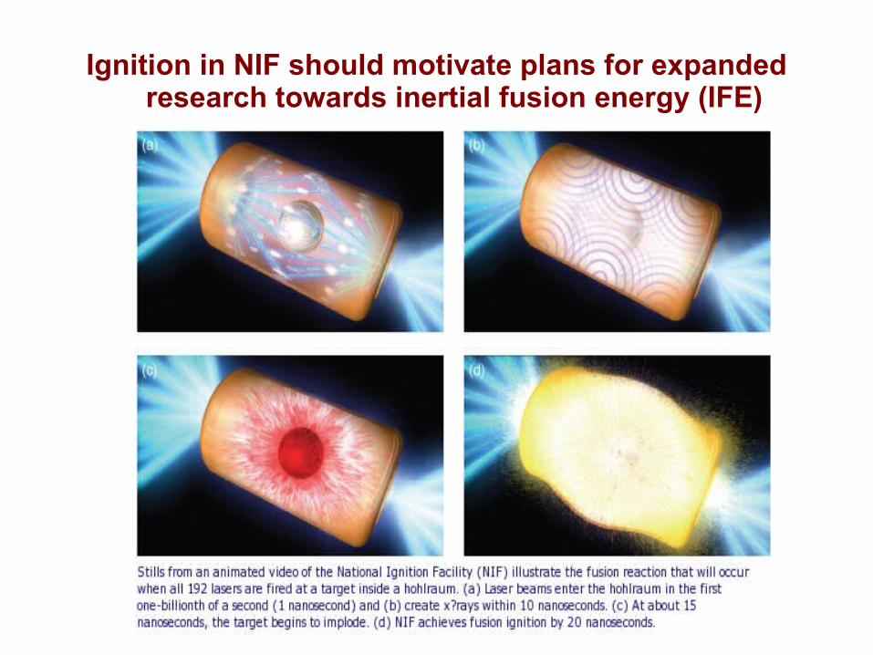
Ignition in NIF should motivate plans for expanded research towards inertial fusion energy (IFE)
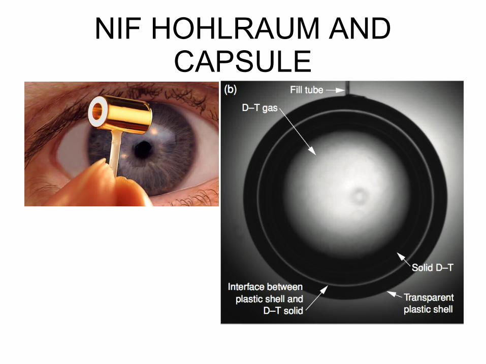
NIF HOHLRAUM AND CAPSULE
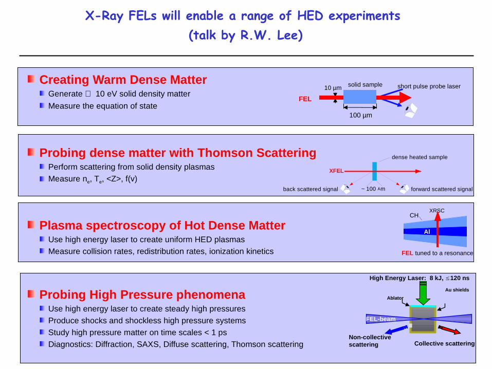
Creating Warm Dense Matter Generate ∼ 10 eV solid density matter
Measure the equation of state
Probing dense matter with Thomson ScatteringPerform scattering from solid density plasmasMeasure ne, Te, <Z>, f(v)
Plasma spectroscopy of Hot Dense MatterUse high energy laser to create uniform HED plasmasMeasure collision rates, redistribution rates, ionization kinetics
Probing High Pressure phenomenaUse high energy laser to create steady high pressuresProduce shocks and shockless high pressure systems
Study high pressure matter on time scales < 1 psDiagnostics: Diffraction, SAXS, Diffuse scattering, Thomson scattering
CH
Al
FEL tuned to a resonance
XRSC
XFEL
dense heated sample
forward scattered signalback scattered signal ~ 100 mᄉ
FEL
10 µm
100 µm
solid sample short pulse probe laser
High Energy Laser: 8 kJ, 120 ns≤
Non-collective scattering Collective scattering
Ablator
Au shields
FEL-beam
X-Ray FELs will enable a range of HED experiments (talk by R.W. Lee)
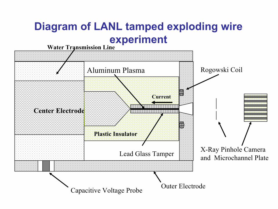
Capacitive Voltage Probe
Rogowski CoilAluminum Plasma
Lead Glass TamperX-Ray Pinhole Cameraand Microchannel Plate
Plastic Insulator
Center Electrode
Water Transmission Line
Current
Outer Electrode
Diagram of LANL tamped exploding wire experiment
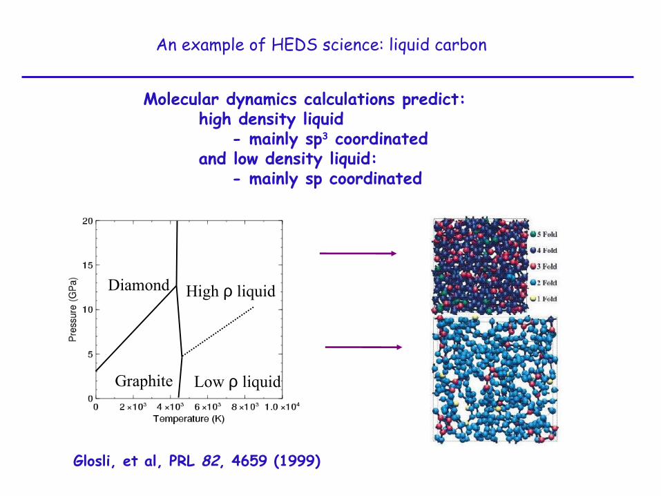
Diamond High ρ liquid
Low ρ liquidGraphite
Molecular dynamics calculations predict:high density liquid
- mainly sp3 coordinatedand low density liquid:
- mainly sp coordinated
An example of HEDS science: liquid carbon
Glosli, et al, PRL 82, 4659 (1999)
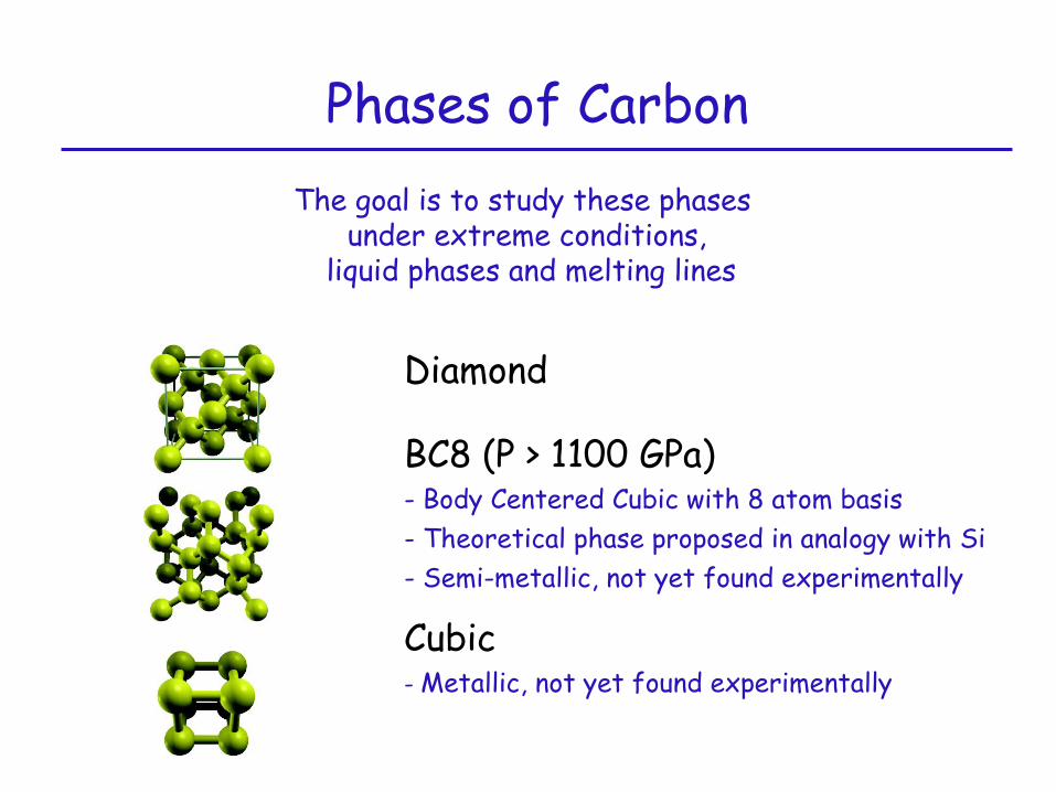
Phases of Carbon
Diamond
BC8 (P > 1100 GPa)- Body Centered Cubic with 8 atom basis- Theoretical phase proposed in analogy with Si - Semi-metallic, not yet found experimentally
Cubic- Metallic, not yet found experimentally
The goal is to study these phases under extreme conditions,
liquid phases and melting lines
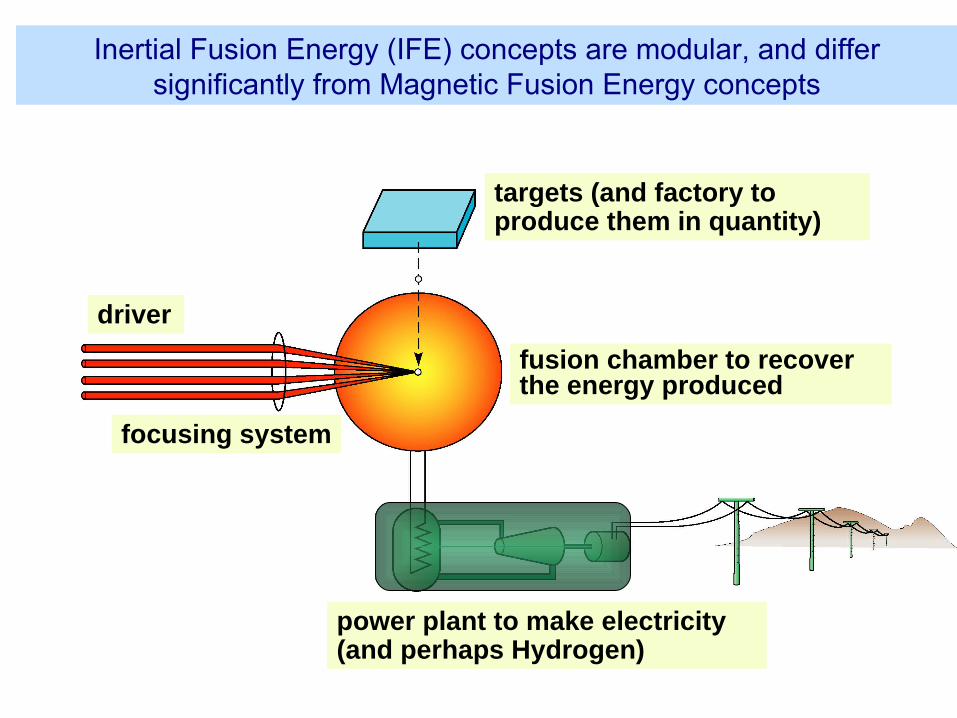
power plant to make electricity (and perhaps Hydrogen)
driver
targets (and factory to produce them in quantity)
Inertial Fusion Energy (IFE) concepts are modular, and differ significantly from Magnetic Fusion Energy concepts
focusing system
fusion chamber to recover the energy produced
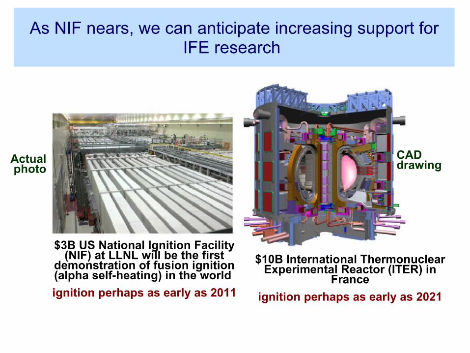
As NIF nears, we can anticipate increasing support for IFE research
$3B US National Ignition Facility (NIF) at LLNL will be the first
demonstration of fusion ignition (alpha self-heating) in the world
ignition perhaps as early as 2011
$10B International Thermonuclear Experimental Reactor (ITER) in
France
ignition perhaps as early as 2021
Actual photo
CAD drawing
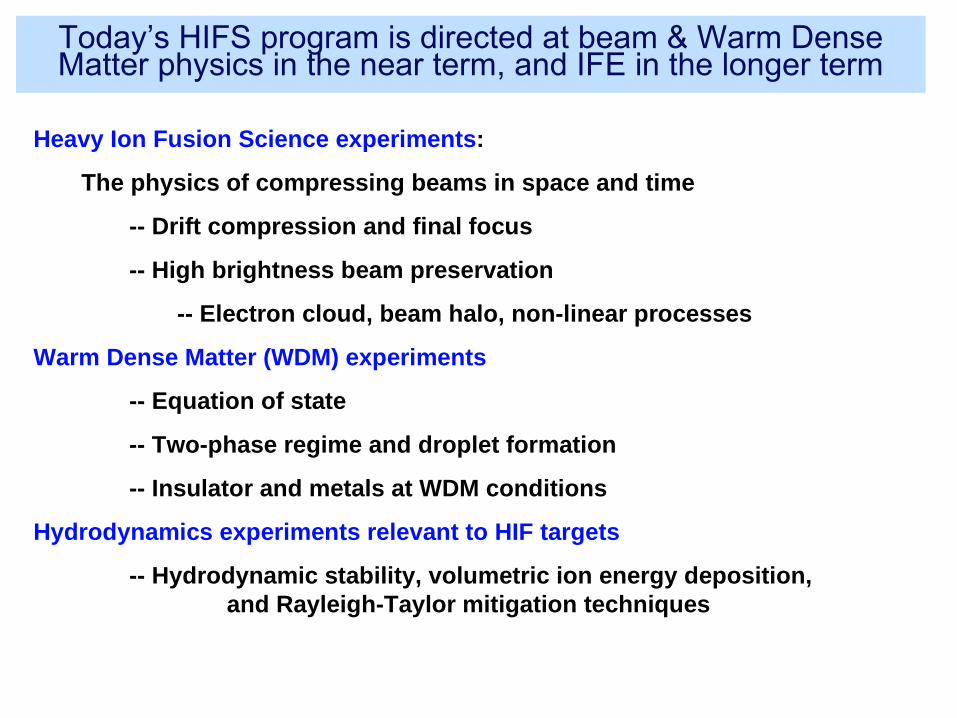
Heavy Ion Fusion Science experiments:
The physics of compressing beams in space and time
-- Drift compression and final focus
-- High brightness beam preservation
-- Electron cloud, beam halo, non-linear processes
Warm Dense Matter (WDM) experiments
-- Equation of state
-- Two-phase regime and droplet formation
-- Insulator and metals at WDM conditions
Hydrodynamics experiments relevant to HIF targets
-- Hydrodynamic stability, volumetric ion energy deposition, and Rayleigh-Taylor mitigation techniques
Today’s HIFS program is directed at beam & Warm Dense Matter physics in the near term, and IFE in the longer term
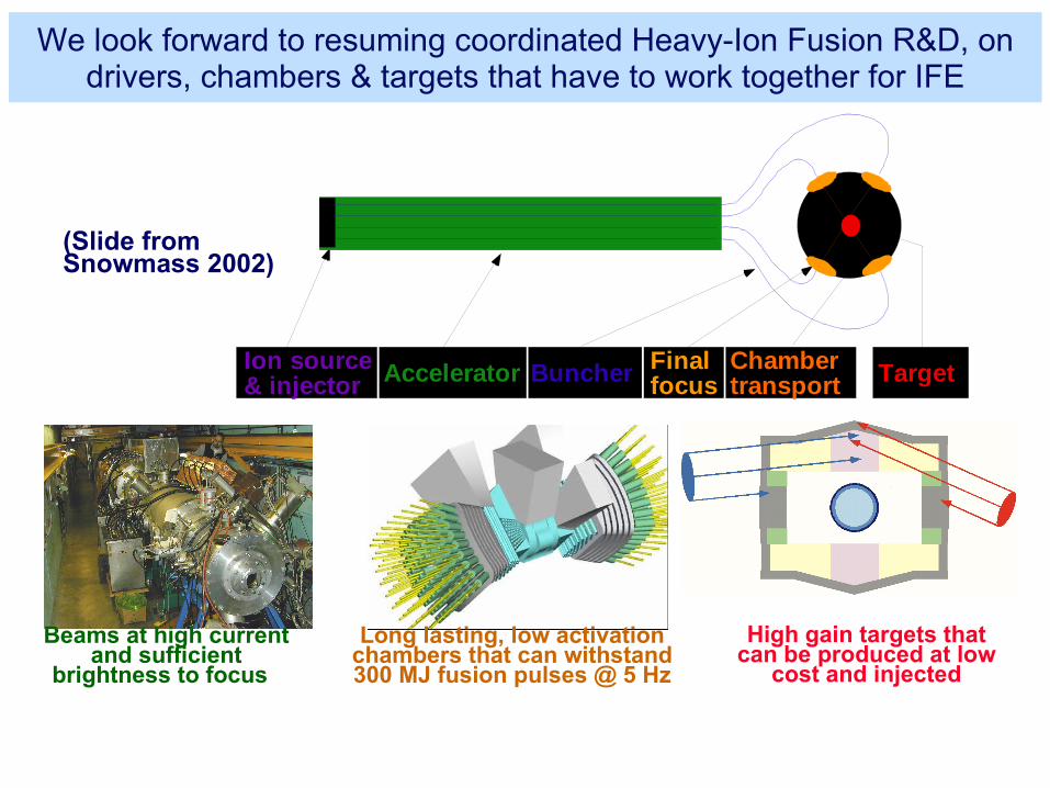
We look forward to resuming coordinated Heavy-Ion Fusion R&D, on drivers, chambers & targets that have to work together for IFE
Buncher Finalfocus
Chambertransport TargetIon source
& injector Accelerator
Beams at high current and sufficient
brightness to focus
Long lasting, low activation chambers that can withstand 300 MJ fusion pulses @ 5 Hz
High gain targets that can be produced at low
cost and injected
(Slide from Snowmass 2002)
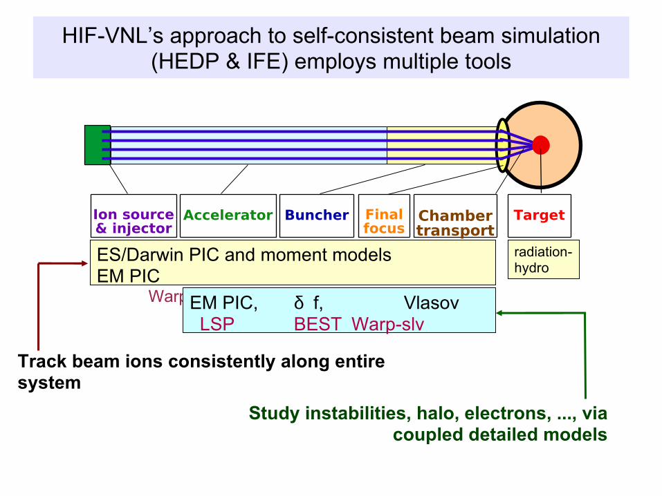
HIF-VNL’s approach to self-consistent beam simulation (HEDP & IFE) employs multiple tools
Ion source& injector
Accelerator Buncher Finalfocus
Chambertransport
Target
Track beam ions consistently along entire system
Study instabilities, halo, electrons, ..., via coupled detailed models
ES/Darwin PIC and moment modelsEM PIC
Warp: 3d, xy, rz , Hermes LSP
EM PIC, δ f, Vlasov LSP BEST Warp-slv
radiation-hydro
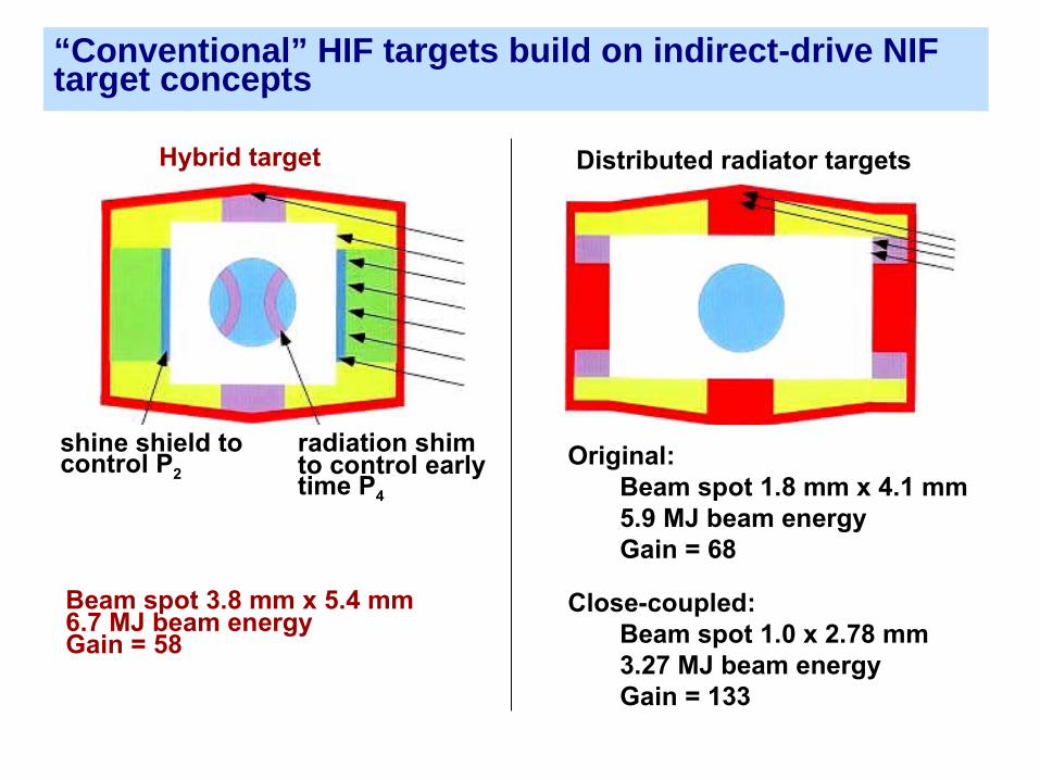
Beam spot 3.8 mm x 5.4 mm6.7 MJ beam energyGain = 58
Original:Beam spot 1.8 mm x 4.1 mm5.9 MJ beam energyGain = 68
Close-coupled:Beam spot 1.0 x 2.78 mm3.27 MJ beam energyGain = 133
shine shield tocontrol P2
radiation shim to control early time P4
Hybrid target Distributed radiator targets
“Conventional” HIF targets build on indirect-drive NIF target concepts
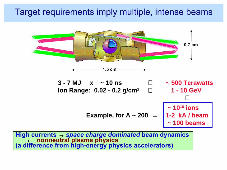
3 - 7 MJ x ~ 10 ns ⇒ ~ 500 TerawattsIon Range: 0.02 - 0.2 g/cm2 ⇒ 1 - 10 GeV ⇓
~ 1016 ions1-2 kA / beam ~ 100 beams
Example, for A ~ 200 →
High currents → space charge dominated beam dynamics → nonneutral plasma physics(a difference from high-energy physics accelerators)
0.7 cm
1.5 cm
Target requirements imply multiple, intense beams
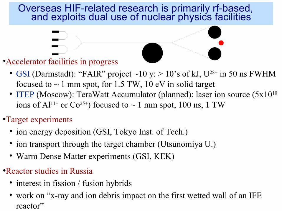
Overseas HIF-related research is primarily rf-based, and exploits dual use of nuclear physics facilities
•Accelerator facilities in progress GSI (Darmstadt): “FAIR” project ~10 y: > 10’s of kJ, U28+ in 50 ns FWHM
focused to ~ 1 mm spot, for 1.5 TW, 10 eV in solid target ITEP (Moscow): TeraWatt Accumulator (planned): laser ion source (5x10¹⁰
ions of Al11+ or Co25+) focused to ~ 1 mm spot, 100 ns, 1 TW
•Target experiments ion energy deposition (GSI, Tokyo Inst. of Tech.) ion transport through the target chamber (Utsunomiya U.) Warm Dense Matter experiments (GSI, KEK)
•Reactor studies in Russia interest in fission / fusion hybrids work on “x-ray and ion debris impact on the first wetted wall of an IFE
reactor”
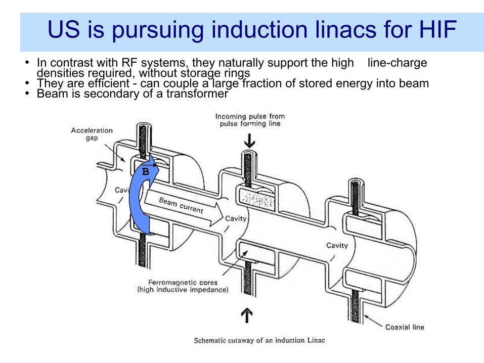
US is pursuing induction linacs for HIF• In contrast with RF systems, they naturally support the high line-charge
densities required, without storage rings• They are efficient - can couple a large fraction of stored energy into beam• Beam is secondary of a transformer
B
Vay - 4/25/06 26
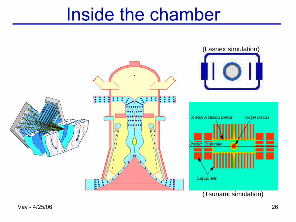
Inside the chamber
(Lasnex simulation)
(Tsunami simulation)
HIF/WDM beam science: neutralized focusing and drift compression are now being tested for use in WDM and HIF
•Both techniques virtually eliminate the repulsive effects of space charge on transverse and longitudinal compression
Transverse compression (= focusing the beam to a small spot, raising the watts/cm2): Recent VNL experiments, eg. scaled final focus experiment, (MacLaren et al 2002), NTX (Roy et al 2004), and current NDCX-1 have demonstrated benefits of neutralization by plasmas, also required for HIF.
Longitudinal compression (= raising the watts): WDM experiments require very short, intense pulses (<~ 1 ns) (shorter than needed for HIF). Neutralization allows high current/high power beams. Modular HIF concept also pushes limit of high current.
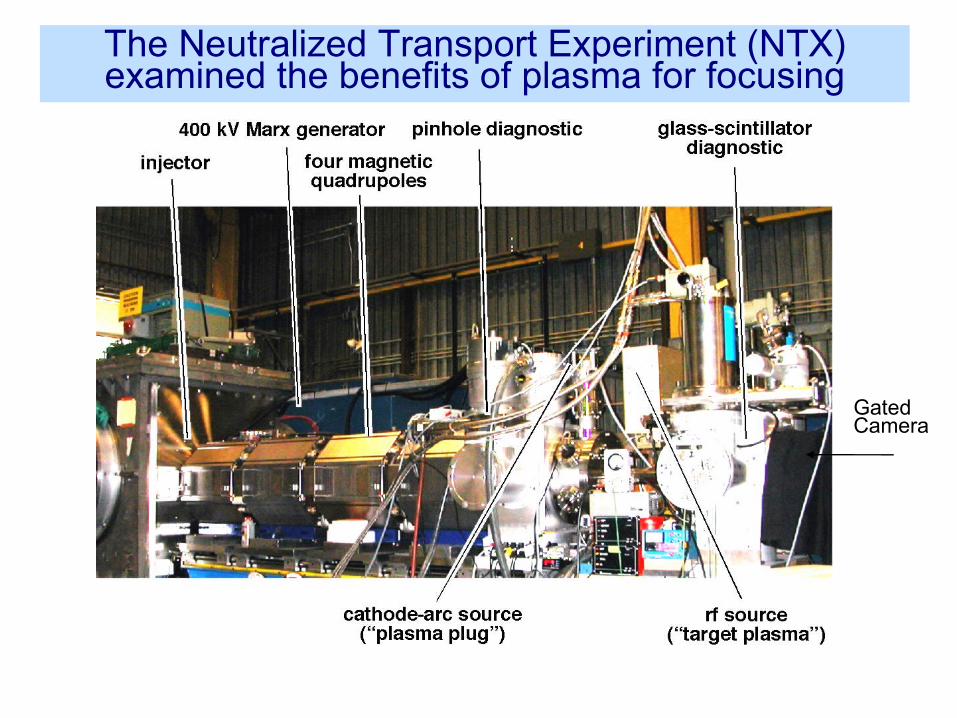
The Neutralized Transport Experiment (NTX) examined the benefits of plasma for focusing
GatedCamera
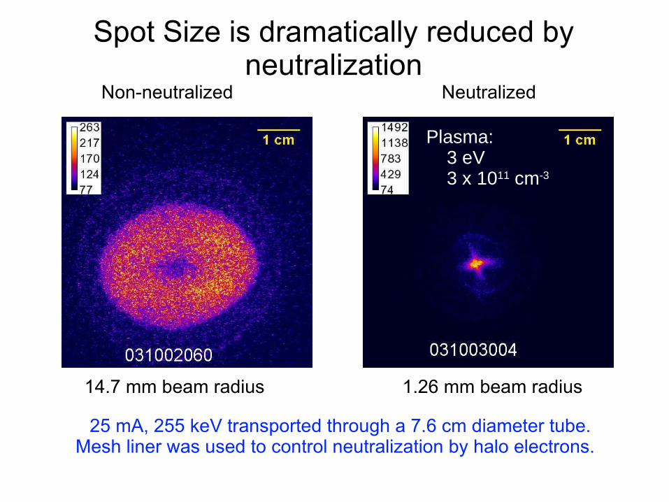
Spot Size is dramatically reduced by neutralization
Non-neutralized Neutralized
25 mA, 255 keV transported through a 7.6 cm diameter tube.Mesh liner was used to control neutralization by halo electrons.
14.7 mm beam radius 1.26 mm beam radius
Plasma: 3 eV 3 x 1011 cm-3
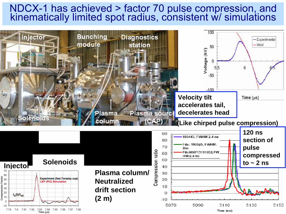
120 ns section of pulsecompressed to ~ 2 ns
QuickTimeᆰ and aTIFF ( LZ W ) dec om p ressor .areneeded to see thispicture
Solenoids
Plasma column/Neutralizeddrift section(2 m)
Injector
Velocity tilt accelerates tail, decelerates head
(Like chirped pulse compression)
NDCX-1 has achieved > factor 70 pulse compression, and kinematically limited spot radius, consistent w/ simulations
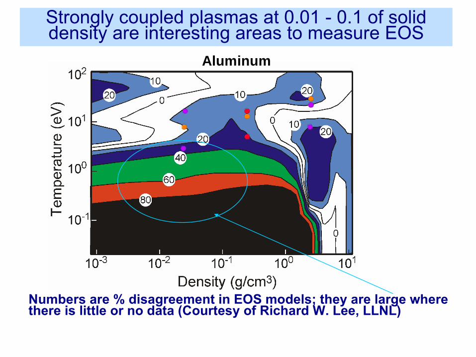
Aluminum
Numbers are % disagreement in EOS models; they are large where there is little or no data (Courtesy of Richard W. Lee, LLNL)
Strongly coupled plasmas at 0.01 - 0.1 of solid density are interesting areas to measure EOS
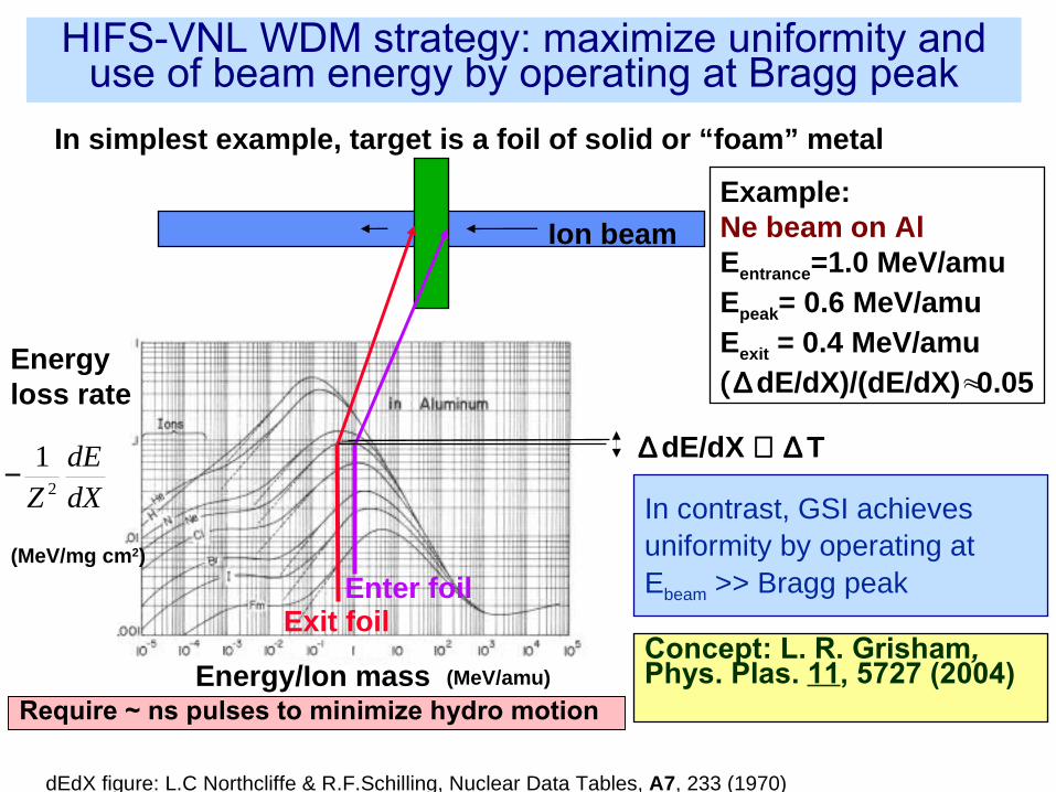
Ion beam
In simplest example, target is a foil of solid or “foam” metal
Enter foilExit foil
∆ dE/dX ∝ ∆ T
Example:Ne beam on Al Eentrance=1.0 MeV/amuEpeak= 0.6 MeV/amuEexit = 0.4 MeV/amu( ∆ dE/dX)/(dE/dX) 0.05≈
ᅠ
− 1Z 2
dEdX
Energyloss rate
Energy/Ion mass
(MeV/mg cm2)
(MeV/amu)
dEdX figure: L.C Northcliffe & R.F.Schilling, Nuclear Data Tables, A7, 233 (1970)
Concept: L. R. Grisham, Phys. Plas. 11, 5727 (2004)
In contrast, GSI achieves uniformity by operating at Ebeam >> Bragg peak
Require ~ ns pulses to minimize hydro motion
HIFS-VNL WDM strategy: maximize uniformity and use of beam energy by operating at Bragg peak
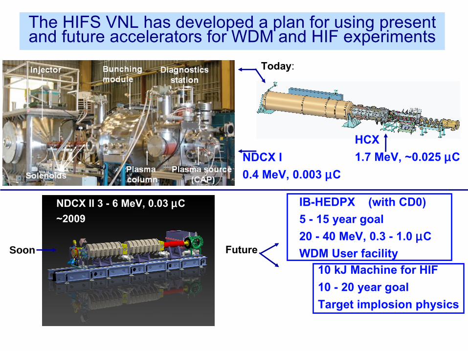
NDCX II 3 - 6 MeV, 0.03 µC
~2009
IB-HEDPX (with CD0)
5 - 15 year goal
20 - 40 MeV, 0.3 - 1.0 µC
WDM User facility
NDCX I
0.4 MeV, 0.003 µC
HCX
1.7 MeV, ~0.025 µC
Today:
Future
10 kJ Machine for HIF
10 - 20 year goal
Target implosion physics
Soon
The HIFS VNL has developed a plan for using present and future accelerators for WDM and HIF experiments
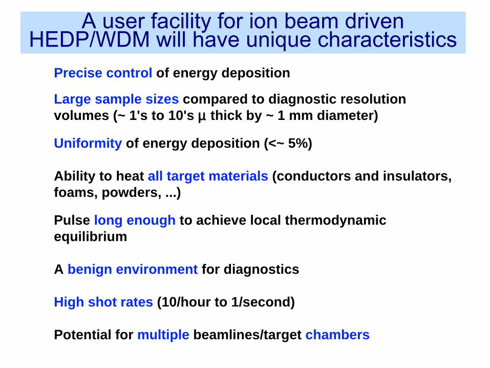
Precise control of energy deposition
Large sample sizes compared to diagnostic resolution volumes (~ 1's to 10's µ thick by ~ 1 mm diameter)
Uniformity of energy deposition (<~ 5%)
Ability to heat all target materials (conductors and insulators, foams, powders, ...) Pulse long enough to achieve local thermodynamic equilibrium
A benign environment for diagnostics High shot rates (10/hour to 1/second) Potential for multiple beamlines/target chambers
A user facility for ion beam driven HEDP/WDM will have unique characteristics
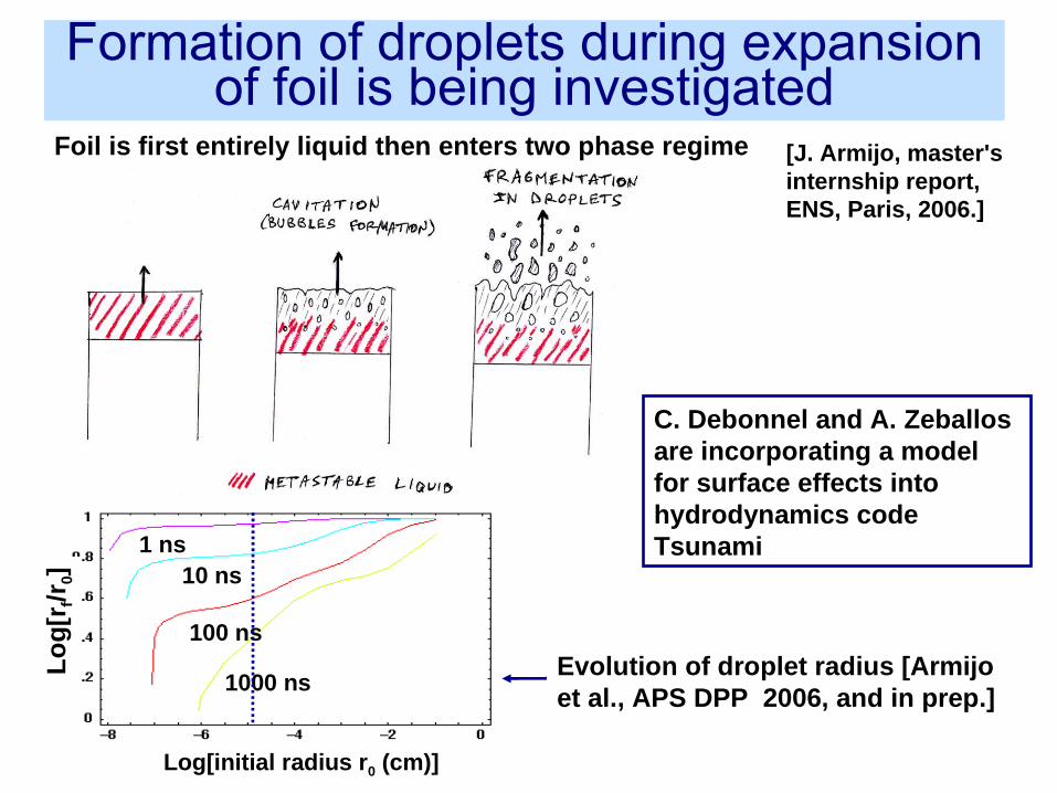
[J. Armijo, master's internship report, ENS, Paris, 2006.]
Foil is first entirely liquid then enters two phase regime
1 ns10 ns
100 ns
1000 ns
C. Debonnel and A. Zeballos are incorporating a model for surface effects into hydrodynamics code Tsunami
Evolution of droplet radius [Armijoet al., APS DPP 2006, and in prep.]
Log[initial radius r0 (cm)]
Lo
g[r
f/r0]
Formation of droplets during expansion of foil is being investigated
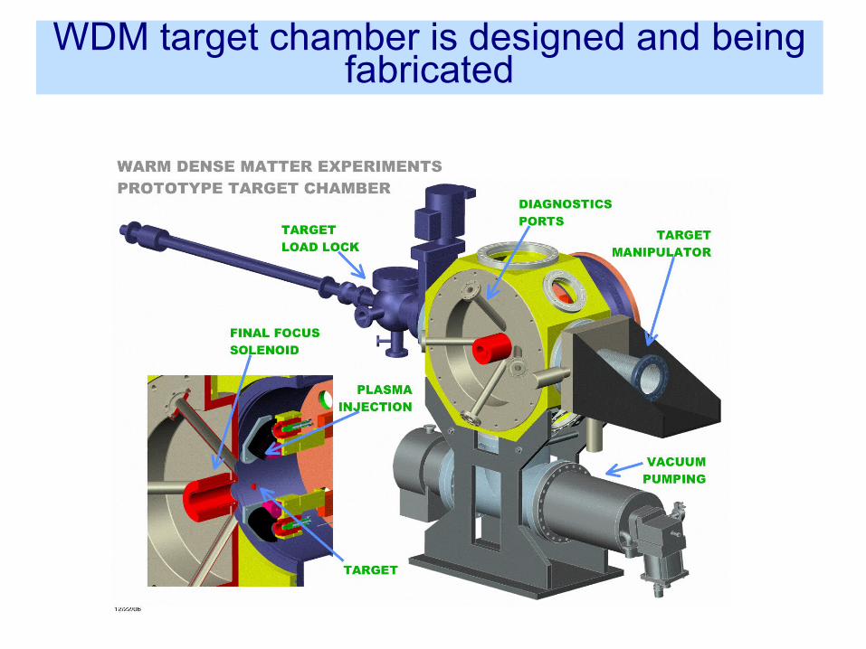
WDM target chamber is designed and being fabricated
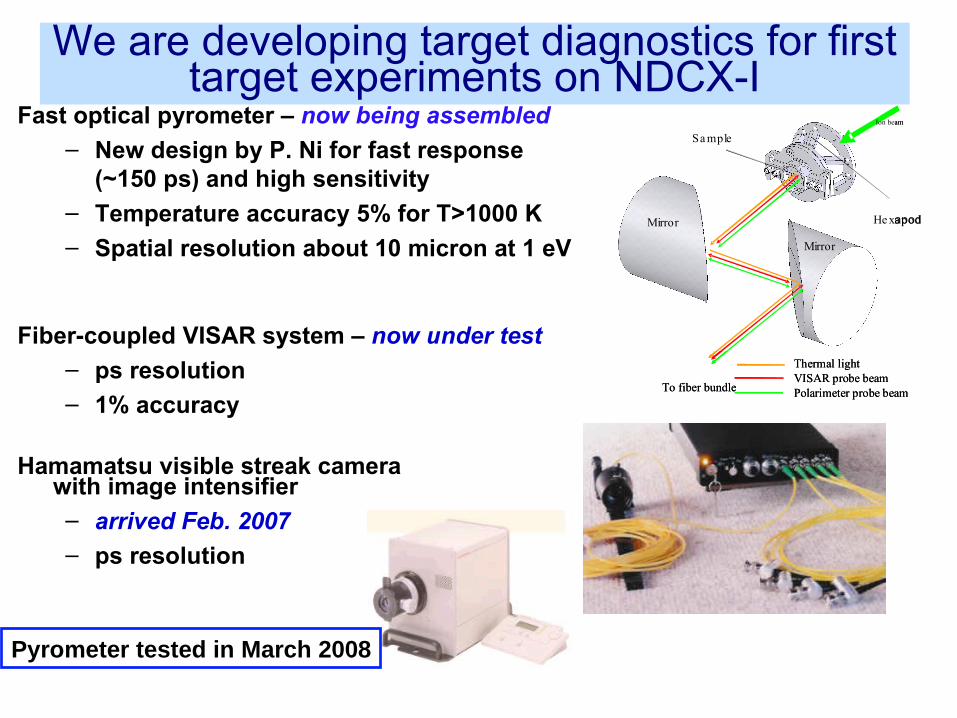
Fast optical pyrometer – now being assembled
– New design by P. Ni for fast response (~150 ps) and high sensitivity
– Temperature accuracy 5% for T>1000 K– Spatial resolution about 10 micron at 1 eV
Fiber-coupled VISAR system – now under test – ps resolution– 1% accuracy
Hamamatsu visible streak camera with image intensifier – arrived Feb. 2007– ps resolution
Hexapod
Sample
Mirror
Mirror
Thermal lightVISAR probe beamPolarimeter probe beamTo fiber bundle
Ion beam
He xapod
Sa mple
Mirror
Mirror
Thermal lightVISAR probe beamPolarimeter probe beamTo fiber bundle
Ion beam
Pyrometer tested in March 2008
We are developing target diagnostics for first target experiments on NDCX-I
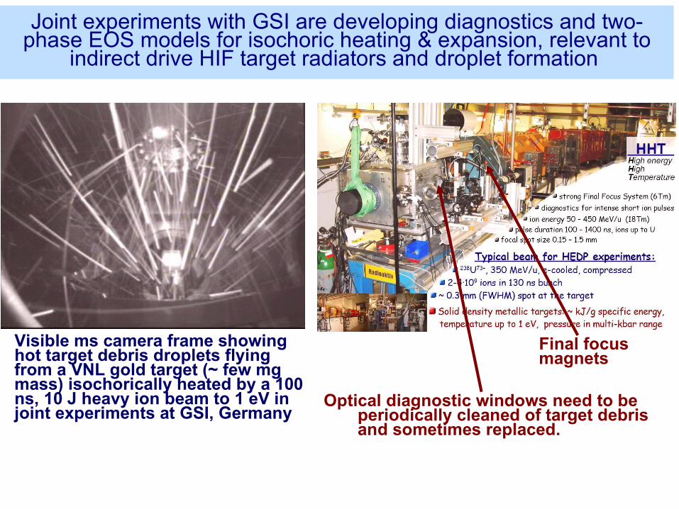
Visible ms camera frame showing hot target debris droplets flying from a VNL gold target (~ few mg mass) isochorically heated by a 100 ns, 10 J heavy ion beam to 1 eV in joint experiments at GSI, Germany
Optical diagnostic windows need to be periodically cleaned of target debris and sometimes replaced.
Final focus magnets
Joint experiments with GSI are developing diagnostics and two-phase EOS models for isochoric heating & expansion, relevant to
indirect drive HIF target radiators and droplet formation
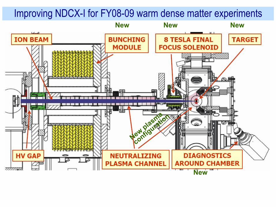
Improving NDCX-I for FY08-09 warm dense matter experimentsNew
New plasma
configura
tion
NewNew
New
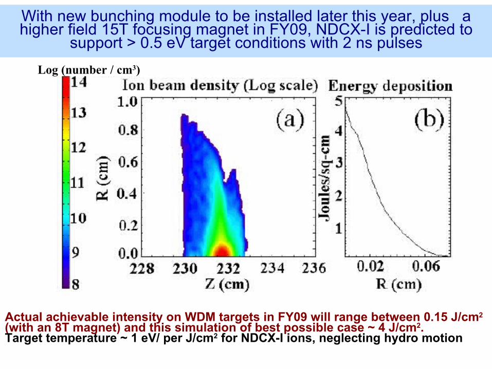
Actual achievable intensity on WDM targets in FY09 will range between 0.15 J/cm2 (with an 8T magnet) and this simulation of best possible case ~ 4 J/cm2. Target temperature ~ 1 eV/ per J/cm2 for NDCX-I ions, neglecting hydro motion
With new bunching module to be installed later this year, plus a higher field 15T focusing magnet in FY09, NDCX-I is predicted to
support > 0.5 eV target conditions with 2 ns pulses
Log (number / cm3)
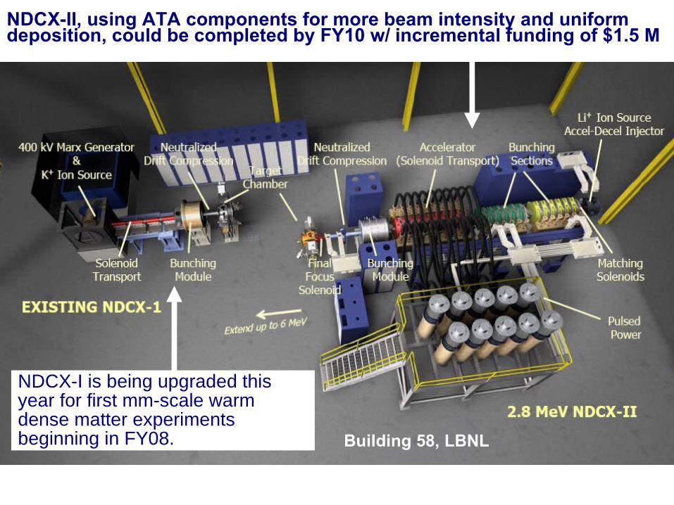
NDCX-II, using ATA components for more beam intensity and uniform deposition, could be completed by FY10 w/ incremental funding of $1.5 M
Building 58, LBNL
NDCX-I is being upgraded this year for first mm-scale warm dense matter experiments beginning in FY08.
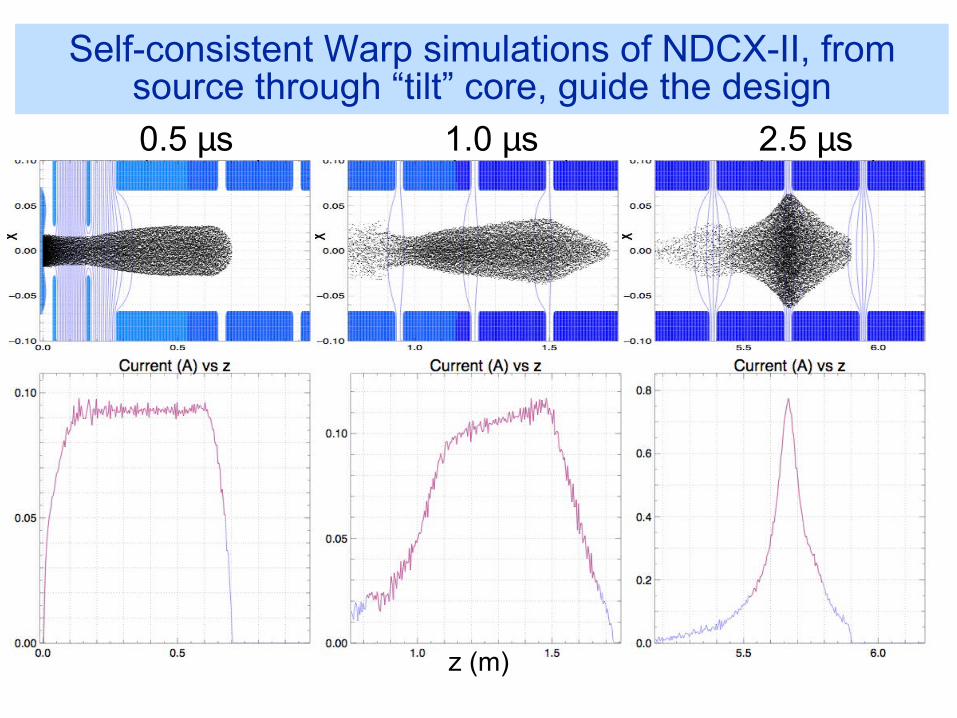
Self-consistent Warp simulations of NDCX-II, from source through “tilt” core, guide the design 0.5 µs 1.0 µs 2.5 µs
z (m)
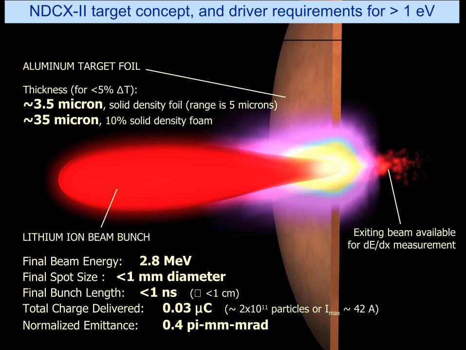
LITHIUM ION BEAM BUNCH
Final Beam Energy: 2.8 MeVFinal Spot Size : <1 mm diameterFinal Bunch Length: <1 ns (≅ <1 cm)
Total Charge Delivered: 0.03 µC (~ 2x10¹¹ particles or Imax ~ 42 A)
Normalized Emittance: 0.4 pi-mm-mrad
ALUMINUM TARGET FOIL
Thickness (for <5% ∆T):~3.5 micron, solid density foil (range is 5 microns)
~35 micron, 10% solid density foam
Exiting beam availablefor dE/dx measurement
NDCX-II target concept, and driver requirements for > 1 eV
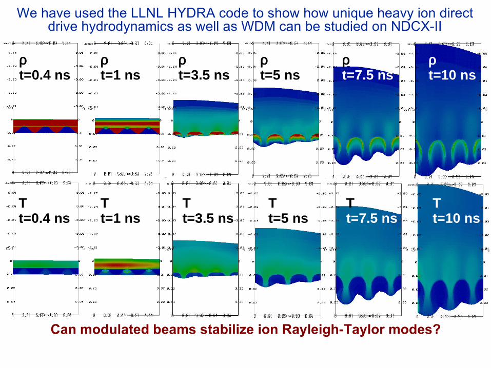
We have used the LLNL HYDRA code to show how unique heavy ion direct drive hydrodynamics as well as WDM can be studied on NDCX-II
ρt=0.4 ns
ρt=1 ns
ρt=3.5 ns
ρt=5 ns
ρt=7.5 ns
ρt=10 ns
Tt=0.4 ns
Tt=1 ns
Tt=3.5 ns
Tt=5 ns
Tt=7.5 ns
Tt=10 ns
Can modulated beams stabilize ion Rayleigh-Taylor modes?
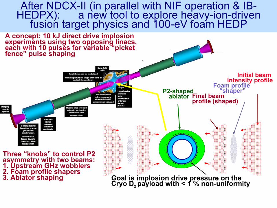
A concept: 10 kJ direct drive implosion experiments using two opposing linacs, each with 10 pulses for variable “picket fence” pulse shaping
Goal is implosion drive pressure on the Cryo D2 payload with < 1 % non-uniformity
Initial beam intensity profile
Foam profile “shaper”
Final beam profile (shaped)
P2-shaped ablator
Three “knobs” to control P2 asymmetry with two beams:1. Upstream GHz wobblers2. Foam profile shapers3. Ablator shaping
After NDCX-II (in parallel with NIF operation & IB-HEDPX): a new tool to explore heavy-ion-driven
fusion target physics and 100-eV foam HEDP
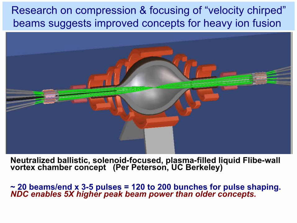
Neutralized ballistic, solenoid-focused, plasma-filled liquid Flibe-wall vortex chamber concept (Per Peterson, UC Berkeley)
Research on compression & focusing of “velocity chirped” beams suggests improved concepts for heavy ion fusion
~ 20 beams/end x 3-5 pulses = 120 to 200 bunches for pulse shaping. NDC enables 5X higher peak beam power than older concepts.
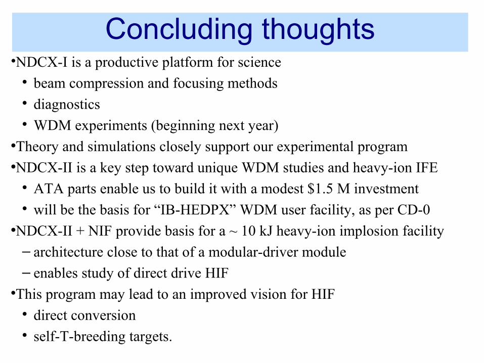
Concluding thoughts•NDCX-I is a productive platform for science
beam compression and focusing methods diagnostics WDM experiments (beginning next year)
•Theory and simulations closely support our experimental program•NDCX-II is a key step toward unique WDM studies and heavy-ion IFE
ATA parts enable us to build it with a modest $1.5 M investment will be the basis for “IB-HEDPX” WDM user facility, as per CD-0
•NDCX-II + NIF provide basis for a ~ 10 kJ heavy-ion implosion facility– architecture close to that of a modular-driver module– enables study of direct drive HIF
This program may lead to an improved vision for HIF direct conversion self-T-breeding targets.


![[PPT]9. Modelos de Alta Freqüência – Pequenos Sinais · Web view9.3 – Modelos de Parâmetros-y Projetos em freqüências muito altas Caixa preta Pode ser usado para algo além](https://static.fdocument.org/doc/165x107/5bed84e709d3f2175d8b9762/ppt9-modelos-de-alta-frequeencia-pequenos-web-view93-modelos-de.jpg)