Draft Tube Flow - NTNU · 2006-02-10 · Swirl flow in draft tubes Anisotropic turbulence • The...
31
Draft Tube Flow
Transcript of Draft Tube Flow - NTNU · 2006-02-10 · Swirl flow in draft tubes Anisotropic turbulence • The...
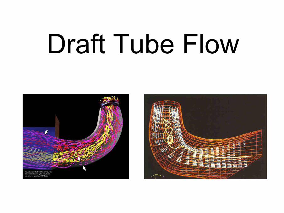
Draft Tube Flow
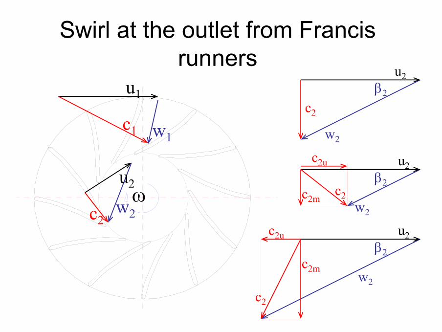
Swirl at the outlet from Francis runners
ω
c1 w1
u1
c2w2
u2
c2
w2
u2β2
c2w2
u2β2
c2m
c2u
c2
w2
u2β2
c2m
c2u
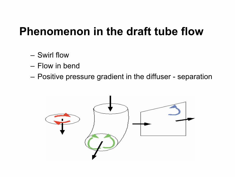
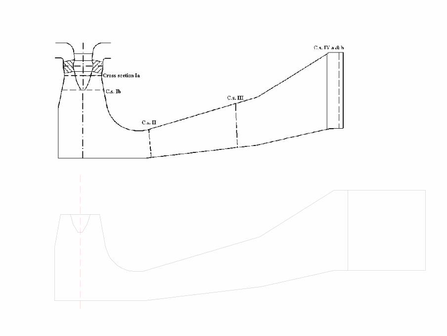
Phenomenon in the draft tube flow
– Swirl flow– Flow in bend– Positive pressure gradient in the diffuser - separation
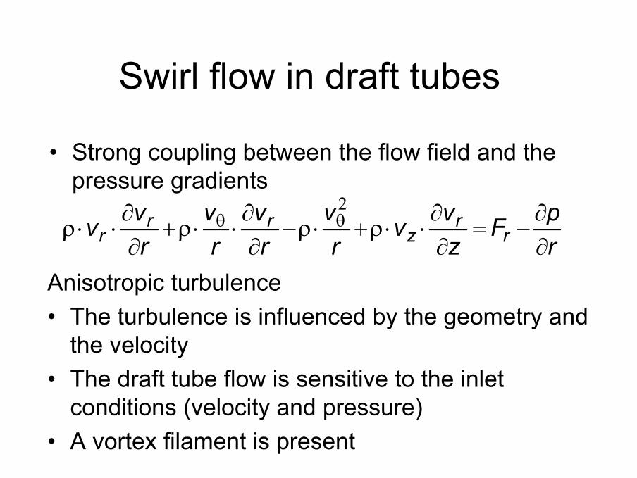
• Strong coupling between the flow field and the pressure gradients
rpF
zvv
rv
rv
rv
rvv r
rz
rrr ∂
∂−=
∂∂⋅⋅ρ+⋅ρ−
∂∂⋅⋅ρ+
∂∂⋅⋅ρ θθ
2
Swirl flow in draft tubes
Anisotropic turbulence• The turbulence is influenced by the geometry and
the velocity• The draft tube flow is sensitive to the inlet
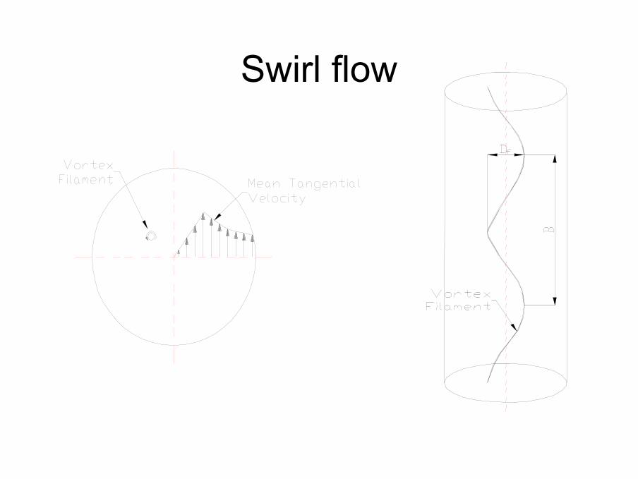
conditions (velocity and pressure)• A vortex filament is present
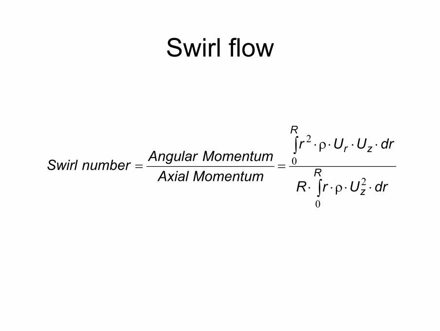
Swirl flow
∫
∫
⋅⋅ρ⋅⋅
⋅⋅⋅ρ⋅== R
z
R
zr
drUrR
drUUr
MomentumAxialMomentumAngularnumberSwirl
0
2
0
2
0,0
0,3
0,6
0,9
1,2
1,5
-1,0 -0,5 0,0 0,5 1,0
Radius [ - ]
Vel
ocity
[ -
]
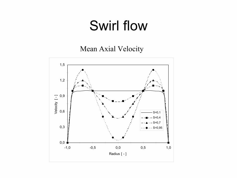
S=0,1
S=0,4
S=0,7
S=0,95
Mean Axial Velocity
Swirl flow
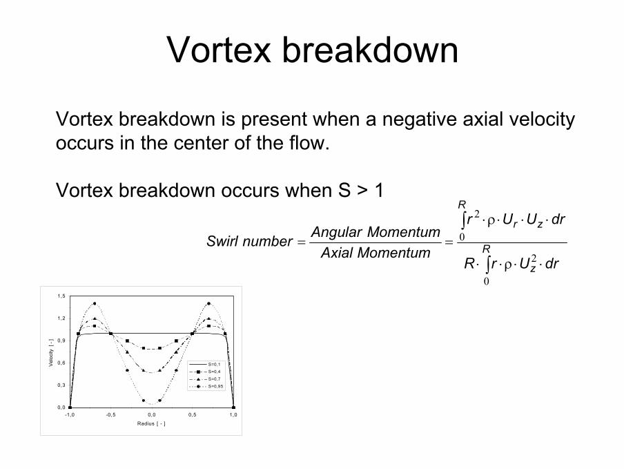
Vortex breakdown
∫
∫
⋅⋅ρ⋅⋅
⋅⋅⋅ρ⋅== R
z
R
zr
drUrR
drUUr
MomentumAxialMomentumAngularnumberSwirl
0
2
0
2
Vortex breakdown is present when a negative axial velocity occurs in the center of the flow.
Vortex breakdown occurs when S > 1
0,0
0,3
0,6
0,9
1,2
1,5
-1,0 -0,5 0,0 0,5 1,0
Radius [ - ]
Vel
ocity
[ -
]
S=0,1
S=0,4
S=0,7
S=0,95
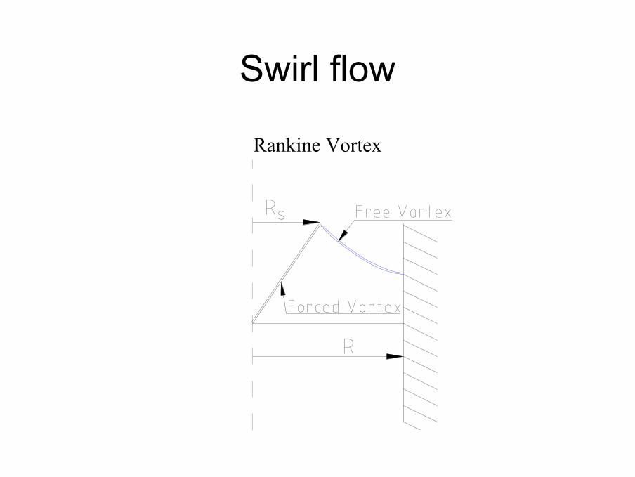
Rankine Vortex
Swirl flow
Swirl flow
Swirl flow
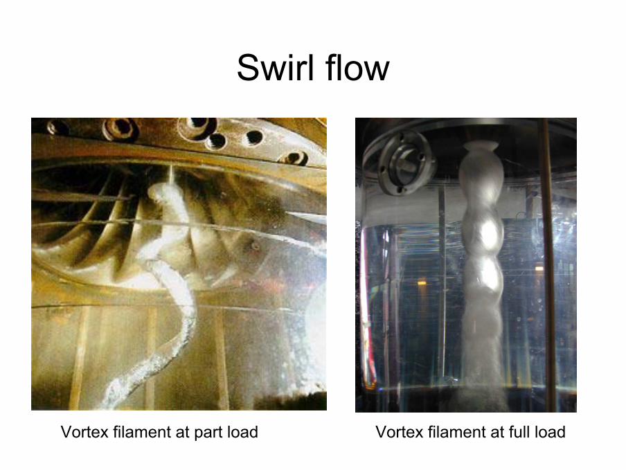
Vortex filament at part load Vortex filament at full load
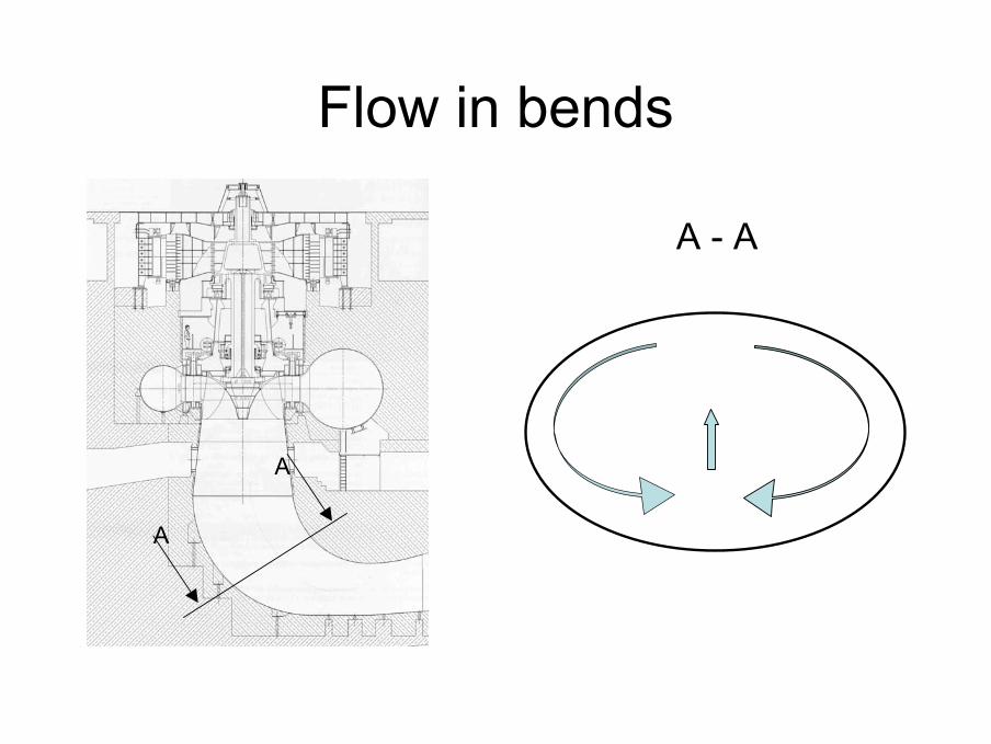
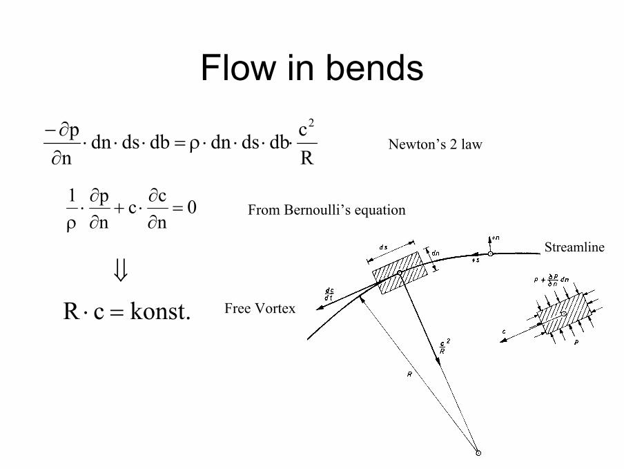
Flow in bends
A
A
A - A
StreamlineStreamline
Rcdbdsdndbdsdn
np 2
⋅⋅⋅⋅ρ=⋅⋅⋅∂∂−
Flow in bends
0ncc
np1
=∂∂⋅+
∂∂⋅
ρ
.konstcR =⋅⇓
Free Vortex
From Bernoulli’s equation
Newton’s 2 law

Positive pressure gradient in the diffuser
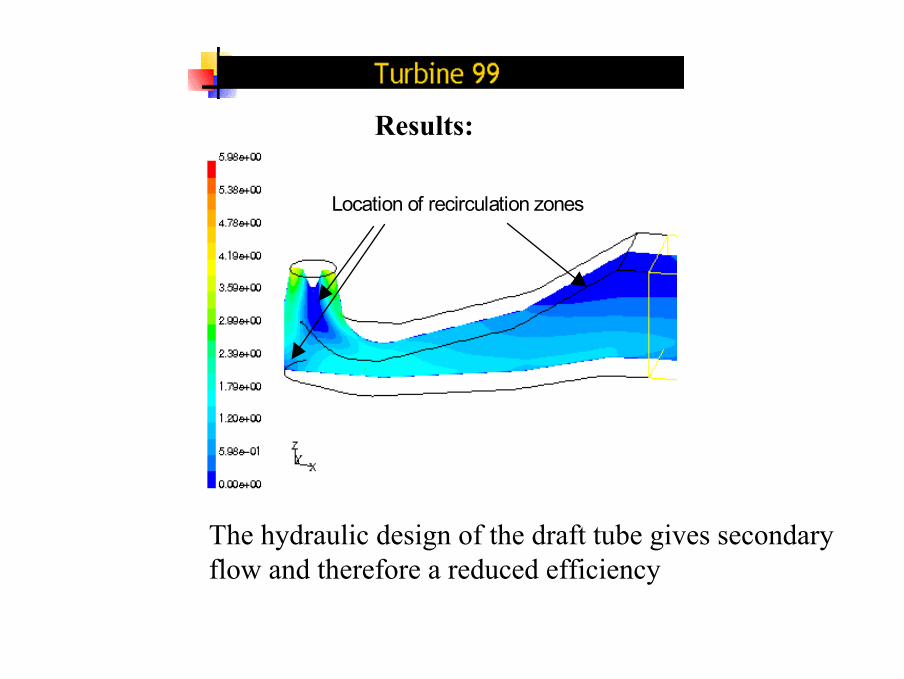
Location of recirculation zones
Results:
The hydraulic design of the draft tube gives secondary flow and therefore a reduced efficiency
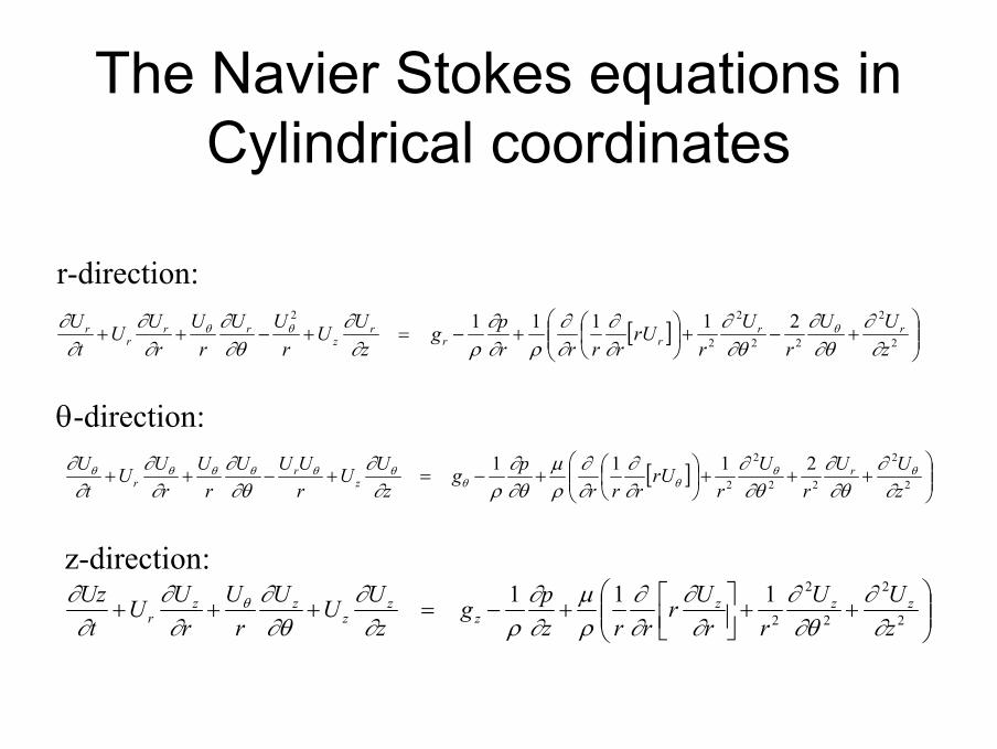
The Navier Stokes equations in Cylindrical coordinates
[ ]
+−+
+−=+−++ 2
2
22
2
2
2 21111zUU
rU
rrU
rrrrpg
zUU
rUU
rU
rUU
tU rr
rrr
zrr
rr
∂∂
∂θ∂
∂θ∂
∂∂
∂∂
ρ∂∂
ρ∂∂
∂θ∂
∂∂
∂∂ θθθ
[ ]
+++
+−=+−++ 2
2
22
2
2
2111zUU
rU
rrU
rrrpg
zUU
rUUU
rU
rUU
tU r
zr
r ∂∂
∂θ∂
∂θ∂
∂∂
∂∂
ρµ
∂θ∂
ρ∂∂
∂θ∂
∂∂
∂∂ θθ
θθθθθθθθ
++
+−=+++ 2
2
2
2
2
111zUU
rrUr
rrzpg
zUUU
rU
rUU
tUz zzz
zz
zzz
r ∂∂
∂θ∂
∂∂
∂∂
ρµ
∂∂
ρ∂∂
∂θ∂
∂∂
∂∂ θ
r-direction:
z-direction:
θ-direction:
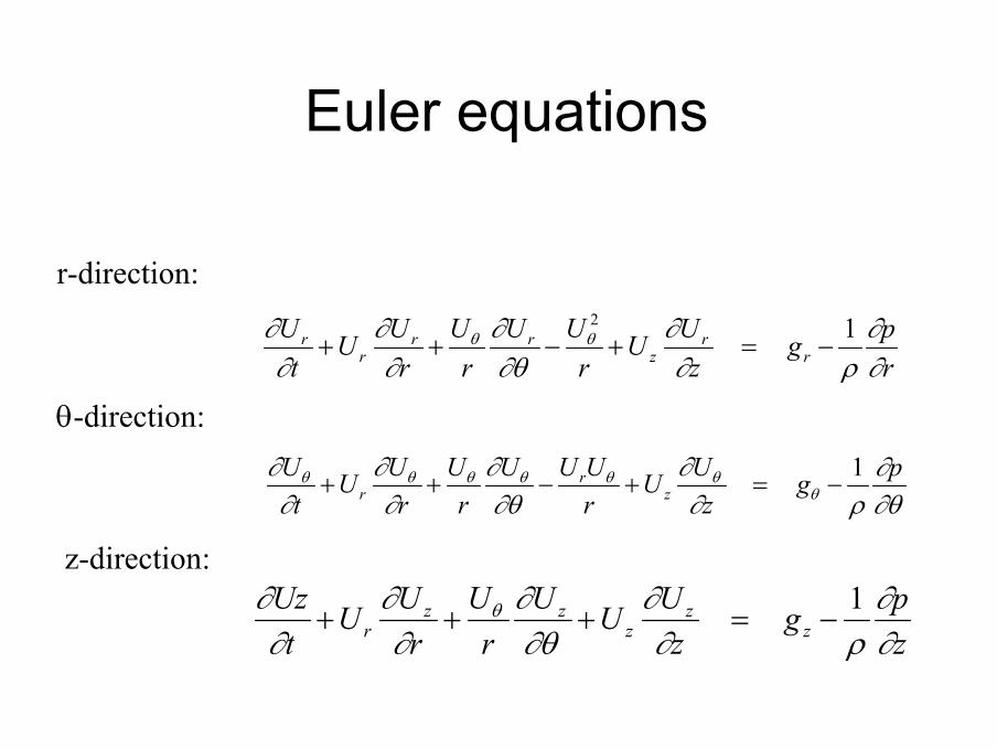
Euler equations
rpg
zUU
rUU
rU
rUU
tU
rr
zrr
rr
∂∂
ρ∂∂
∂θ∂
∂∂
∂∂ θθ 12
−=+−++
∂θ∂
ρ∂∂
∂θ∂
∂∂
∂∂
θθθθθθθ pgzUU
rUUU
rU
rUU
tU
zr
r1
−=+−++
zpg
zUUU
rU
rUU
tUz
zz
zzz
r ∂∂
ρ∂∂
∂θ∂
∂∂
∂∂ θ 1
−=+++
r-direction:
z-direction:
θ-direction:
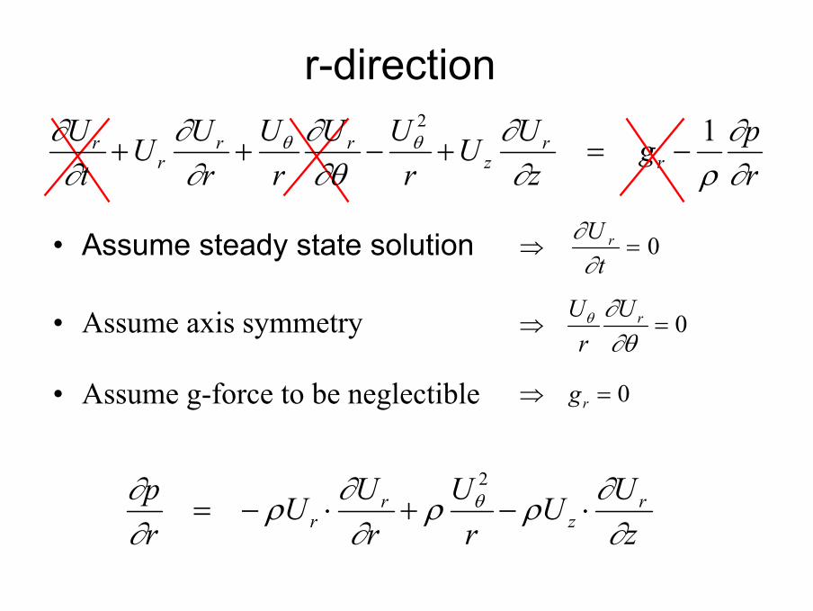
r-direction
• Assume steady state solution 0=⇒tU r
∂∂
• Assume axis symmetry 0=⇒∂θ∂θ rU
rU
zUU
rU
rUU
rp r
zr
r ∂∂ρρ
∂∂ρ
∂∂ θ ⋅−+⋅−=
2
rpg
zUU
rUU
rU
rUU
tU
rr
zrr
rr
∂∂
ρ∂∂
∂θ∂
∂∂
∂∂ θθ 12
−=+−++
• Assume g-force to be neglectible 0=⇒ rg
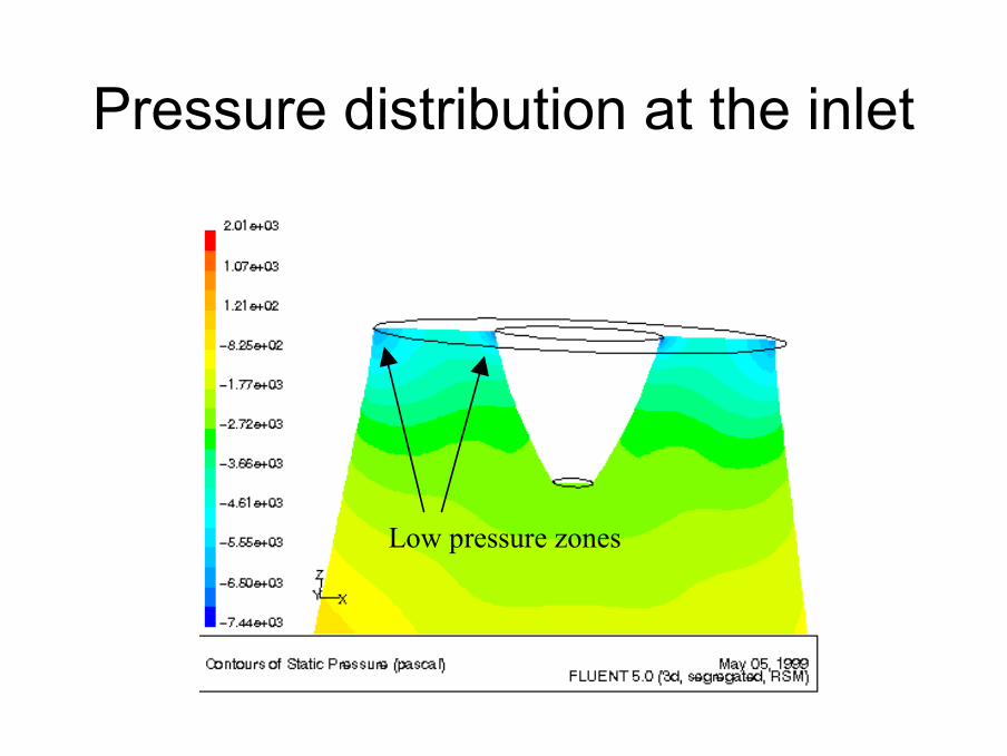
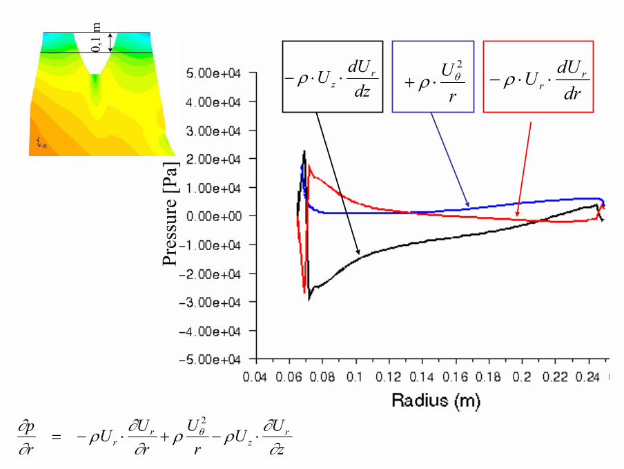
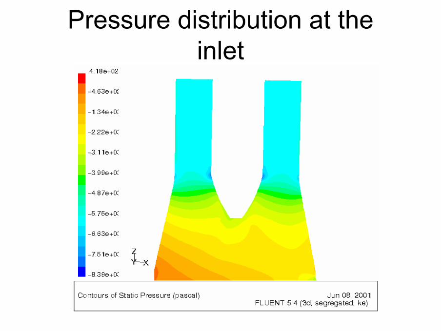
Pressure distribution at the inlet
Low pressure zones
P re s
s ur e
[Pa ]
drdUU r
r ⋅⋅− ρrU 2
θρ ⋅+dzdUU r
z ⋅⋅− ρ0,
1 m
zUU
rU
rUU
rp r
zr
r ∂∂ρρ
∂∂ρ
∂∂ θ ⋅−+⋅−=
2
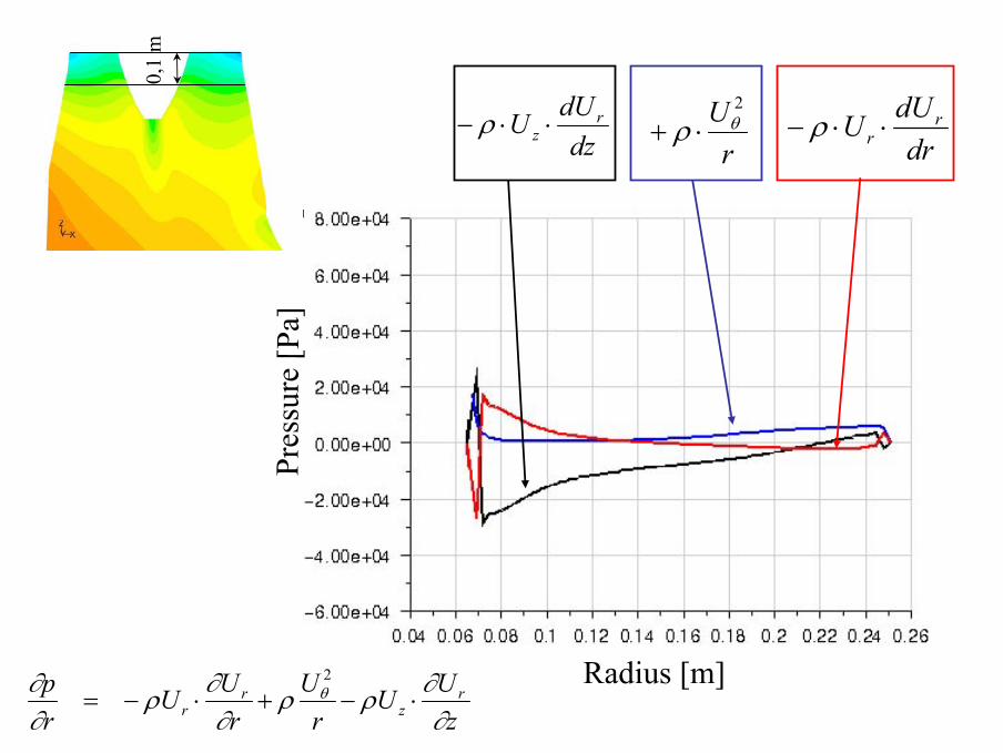
P re s
s ur e
[Pa ]
drdUU r
r ⋅⋅− ρrU 2
θρ ⋅+dzdUU r
z ⋅⋅− ρ0,
1 m
Radius [m]zUU
rU
rUU
rp r
zr
r ∂∂ρρ
∂∂ρ
∂∂ θ ⋅−+⋅−=
2
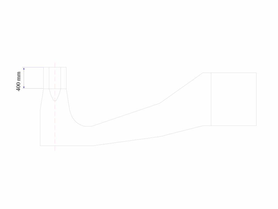
400
mm
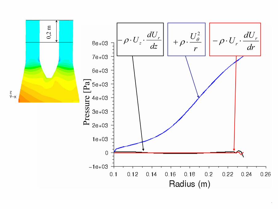
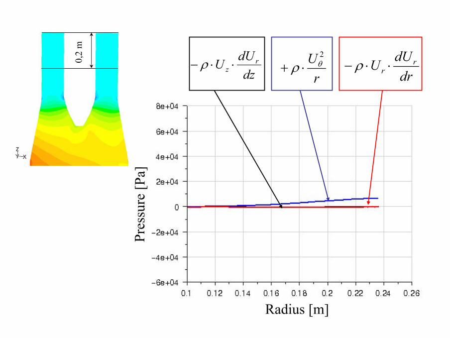
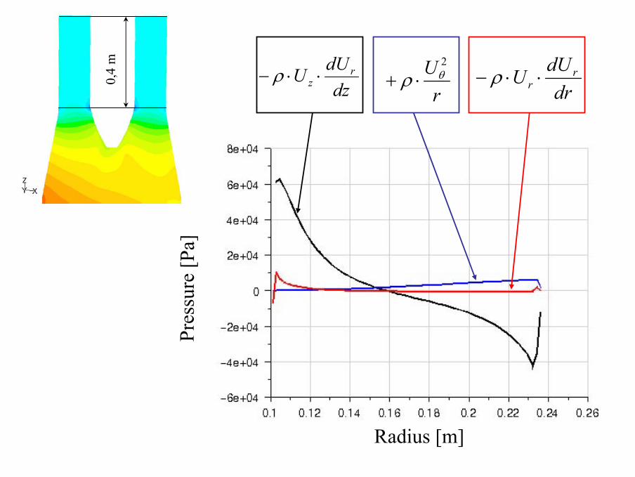
Pressure distribution at theinlet
P re s
s ur e
[Pa ]
drdUU r
r ⋅⋅− ρrU 2
θρ ⋅+dzdUU r
z ⋅⋅− ρ0,2
m
P re s
s ur e
[Pa ]
drdUU r
r ⋅⋅− ρrU 2
θρ ⋅+dzdUU r
z ⋅⋅− ρ0,2
m
Radius [m]
drdUU r
r ⋅⋅− ρrU 2
θρ ⋅+dzdUU r
z ⋅⋅− ρ
P re s
s ur e
[Pa ]
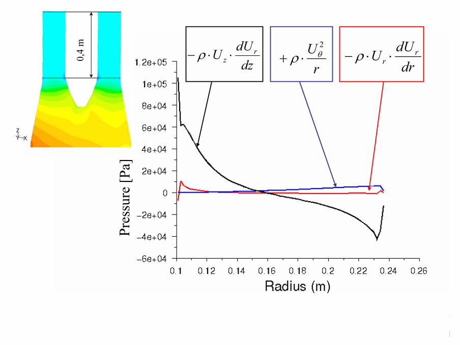
0,4
m
drdUU r
r ⋅⋅− ρrU 2
θρ ⋅+dzdUU r
z ⋅⋅− ρ
P re s
s ur e
[Pa ]
0,4
m
Radius [m]

Static Pressure at the inlet
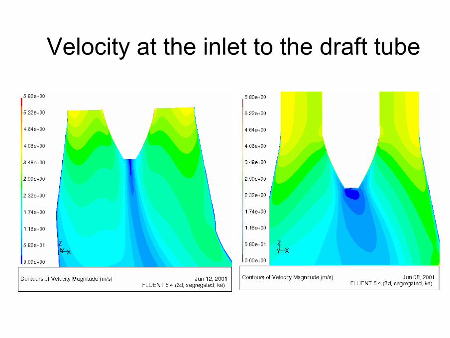
Velocity at the inlet to the draft tube
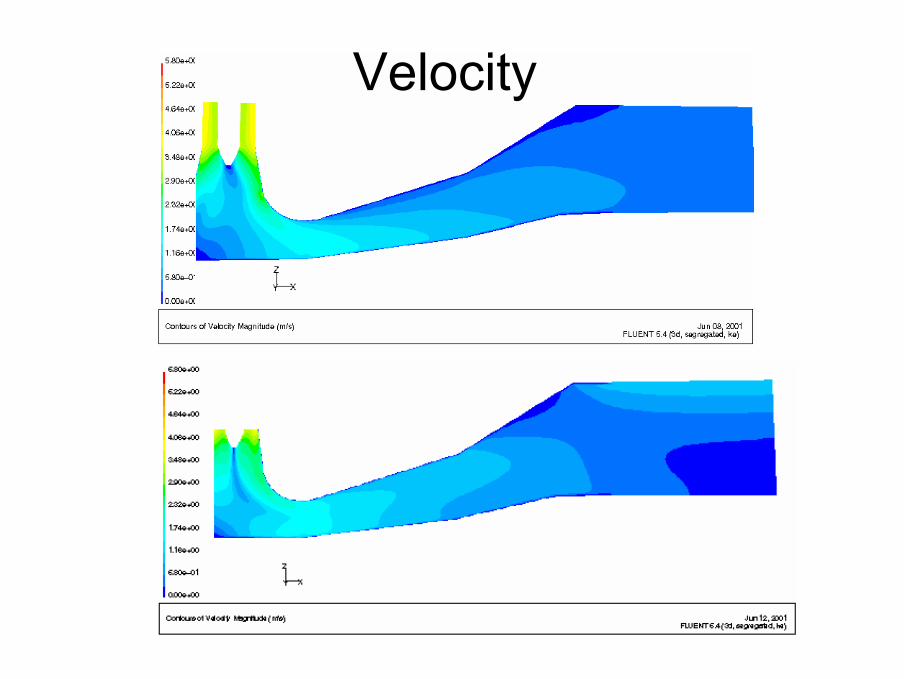
Velocity


![Turbulence in Buoyant Jets using an Integral Flux FormulationZone Of Flow Establishment (ZOFE) described in [2], where the uniform e ux ow turns to fully developed jet ow. The top](https://static.fdocument.org/doc/165x107/5fde8139af59d617d85b4964/turbulence-in-buoyant-jets-using-an-integral-flux-formulation-zone-of-flow-establishment.jpg)