2 2 () ( 2 4 - Universiti Teknologi Malaysiaarahim/skmm3033 final exam example1.pdfQUE a) S b) W c)...
21
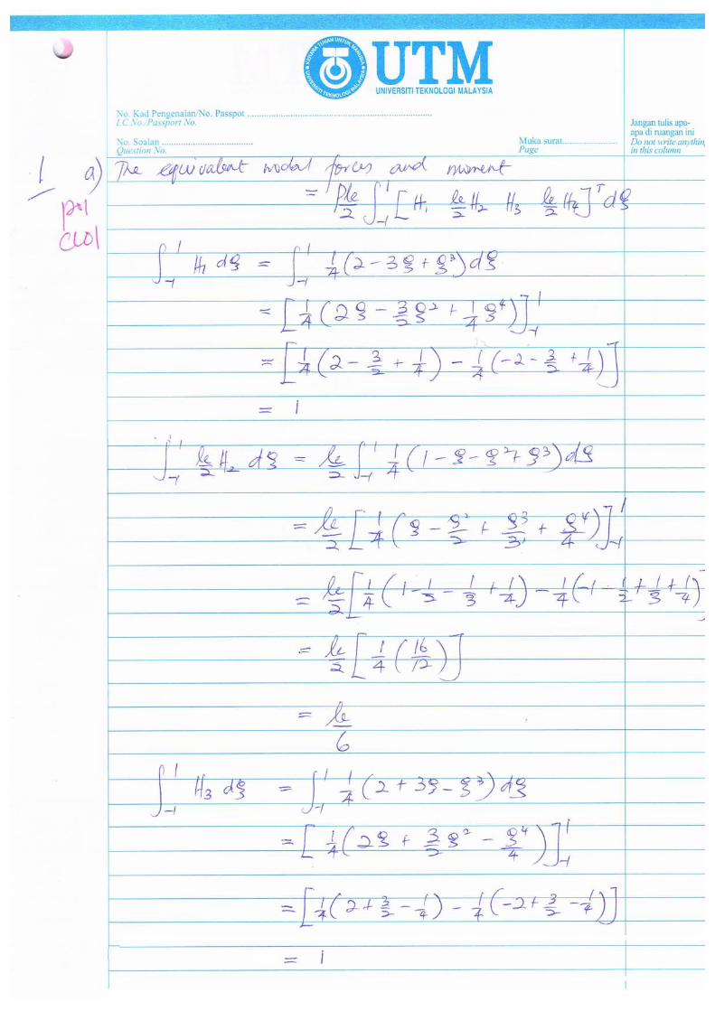
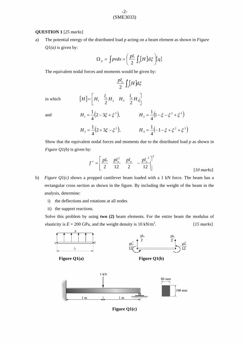
-2- (SME3033) QUESTION 1 [25 marks] a) The potential energy of the distributed load p acting on a beam element as shown in Figure Q1(a) is given by: [ ] {} ∫ ∫ ⎟ ⎠ ⎞ ⎜ ⎝ ⎛ = = Ω − q d H pl pvdx e p 1 1 2 ξ The equivalent nodal forces and moments would be given by: [ ] ∫ − 1 1 2 ξ d H pl e in which [ ] ⎥ ⎦ ⎤ ⎢ ⎣ ⎡ = 4 3 2 1 2 2 H l H H l H H e e and ( ) 3 1 3 2 4 1 ξ ξ + − = H , ( ) 3 2 2 1 4 1 ξ ξ ξ + − − = H ( ) 3 3 3 2 4 1 ξ ξ − + = H , ( ) 3 2 4 1 4 1 ξ ξ ξ + + − − = H Show that the equivalent nodal forces and moments due to the distributed load p as shown in Figure Q1(b) is given by: T e e e e e pl pl pl pl f ⎥ ⎥ ⎦ ⎤ ⎢ ⎢ ⎣ ⎡ − = 12 2 12 2 2 2 [10 marks] b) Figure Q1(c) shows a propped cantilever beam loaded with a 1 kN force. The beam has a rectangular cross section as shown in the figure. By including the weight of the beam in the analysis, determine: i) the deflections and rotations at all nodes ii) the support reactions. Solve this problem by using two (2) beam elements. For the entire beam the modulus of elasticity is E = 200 GPa, and the weight density is 10 kN/m 3 . [15 marks] Figure Q1(a) Figure Q1(b) Figure Q1(c) pl 2 e _ pl 2 e __ pl e __ 2 pl e __ 2 12 12 - p l 1 2 e
Transcript of 2 2 () ( 2 4 - Universiti Teknologi Malaysiaarahim/skmm3033 final exam example1.pdfQUE a) S b) W c)...
-2- (SME3033)
QUESTION 1 [25 marks]
a) The potential energy of the distributed load p acting on a beam element as shown in Figure
Q1(a) is given by:
[ ] { }∫ ∫ ⎟⎠⎞
⎜⎝⎛==Ω
−qdHplpvdx e
p
1
12ξ
The equivalent nodal forces and moments would be given by:
[ ]∫−1
12ξdH
ple
in which [ ] ⎥⎦⎤
⎢⎣⎡= 4321 22
HlHHlHH ee
and ( )31 32
41 ξξ +−=H , ( )32
2 141 ξξξ +−−=H
( )33 32
41 ξξ −+=H , ( )32
4 141 ξξξ ++−−=H
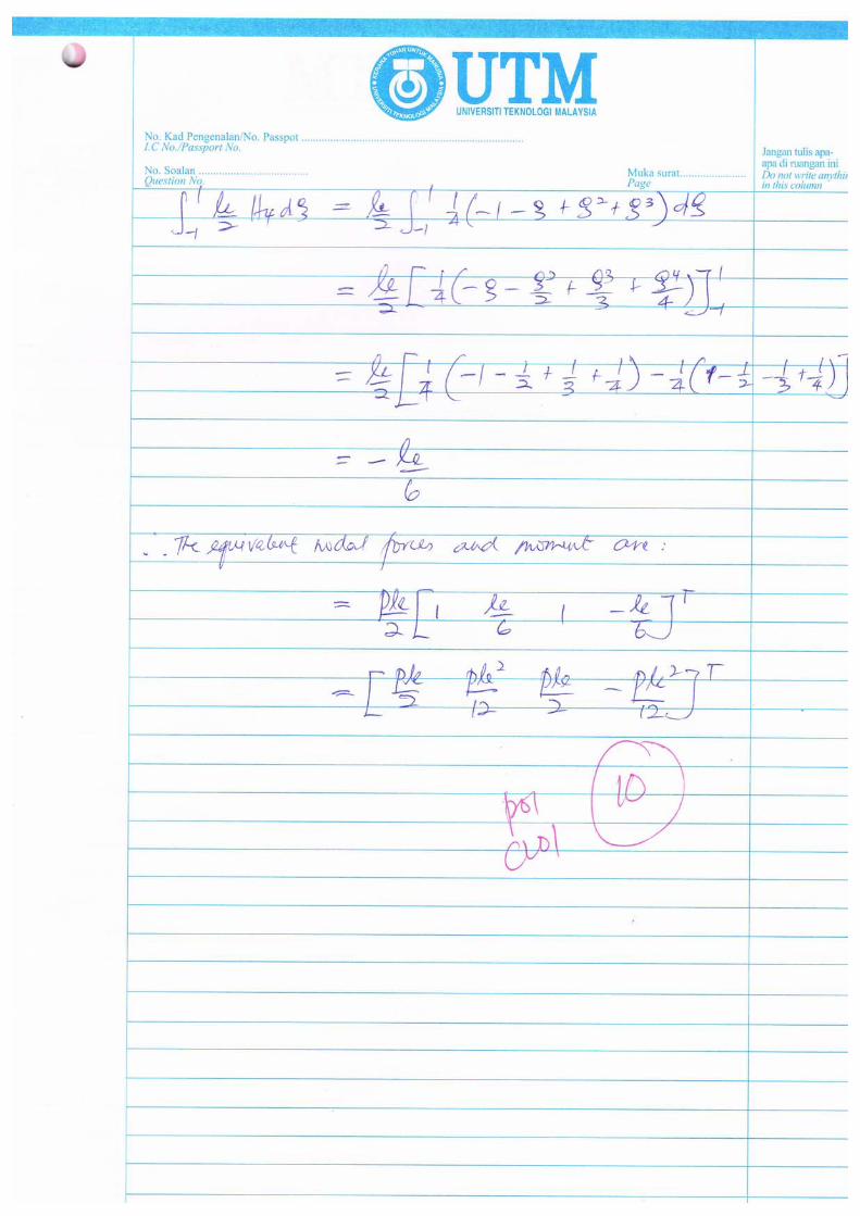
Show that the equivalent nodal forces and moments due to the distributed load p as shown in
Figure Q1(b) is given by:
T
eeeee plplplplf⎥⎥⎦
⎤
⎢⎢⎣
⎡−=
122122
22
[10 marks]
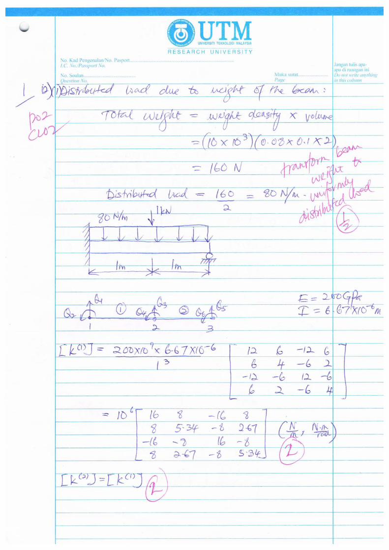
b) Figure Q1(c) shows a propped cantilever beam loaded with a 1 kN force. The beam has a
rectangular cross section as shown in the figure. By including the weight of the beam in the
analysis, determine:
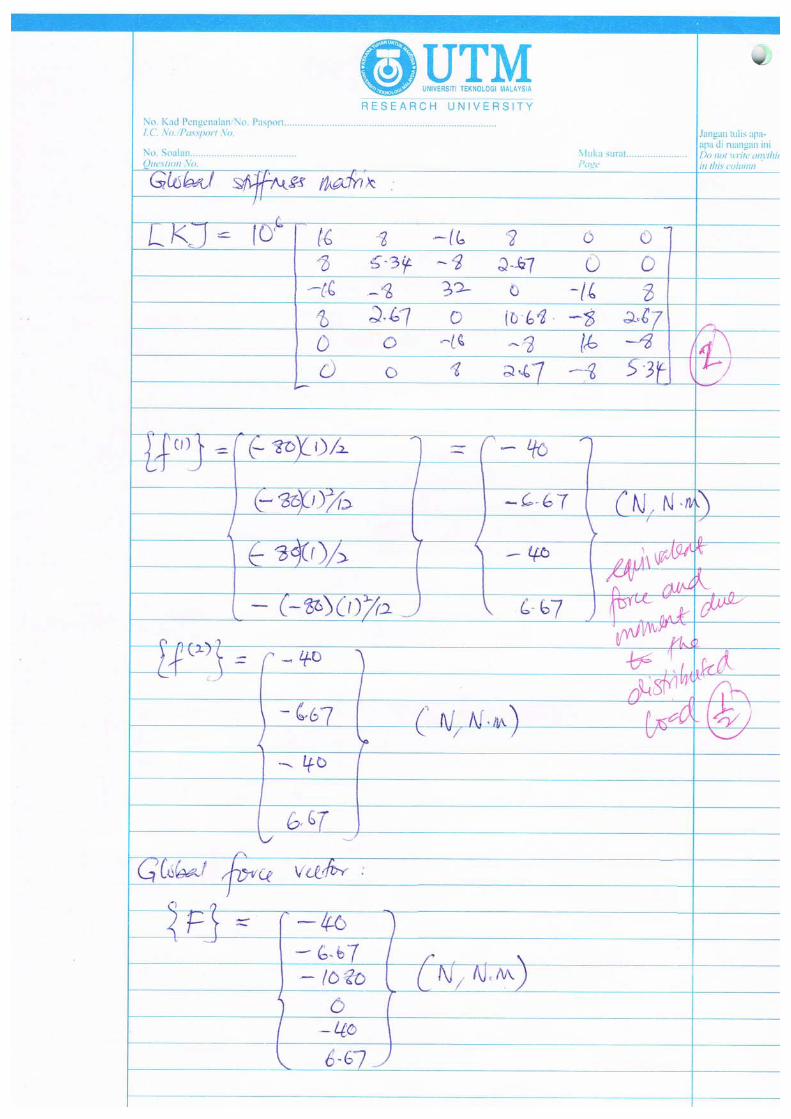
i) the deflections and rotations at all nodes
ii) the support reactions.
Solve this problem by using two (2) beam elements. For the entire beam the modulus of
elasticity is E = 200 GPa, and the weight density is 10 kN/m3. [15 marks]
Figure Q1(a) Figure Q1(b)
Figure Q1(c)
pl2
e_ pl
2
e __
ple__
2pl e __
2
12 12
-
p
l
1 2
e
QUE
a) S
b) W
c) A
f
o
e
i
i
i
ESTION 2 [
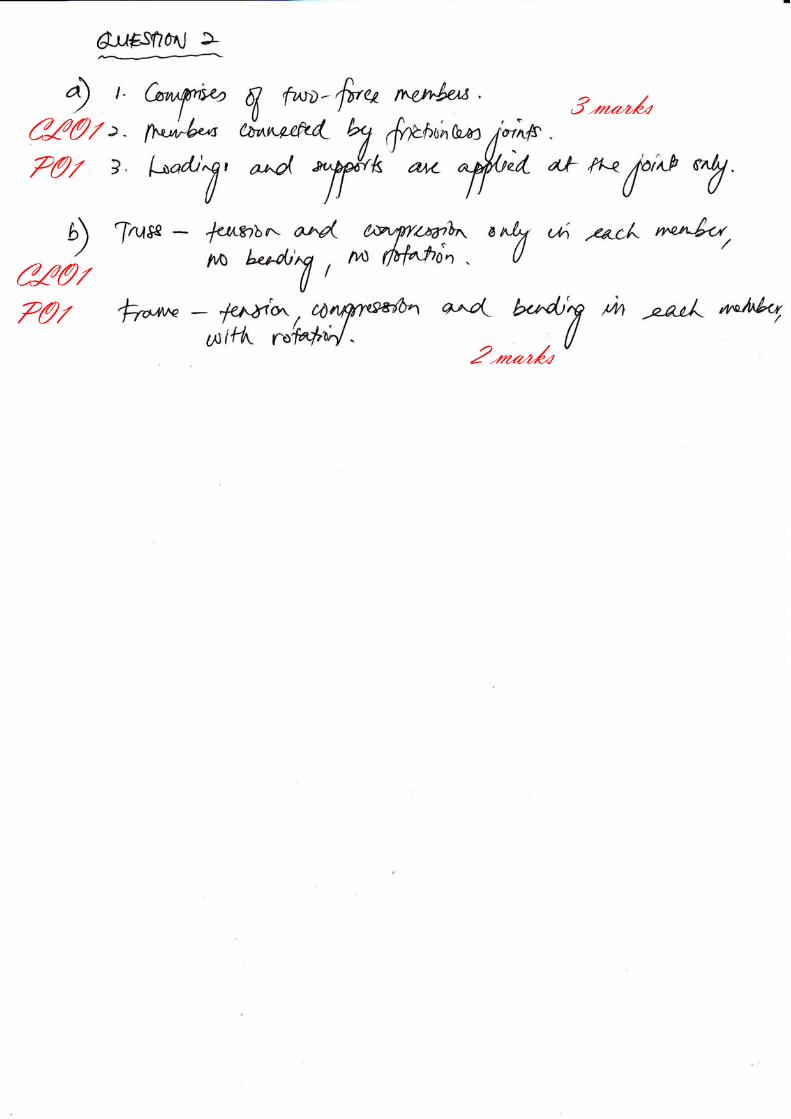
State three m
What is the m
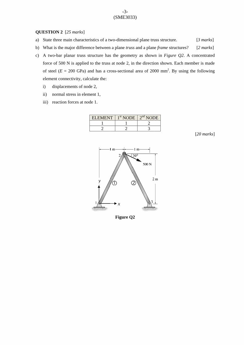
A two-bar p
force of 500
of steel (E =
element conn
) displace
i) normal
ii) reaction
[25 marks]
main characte
major differe
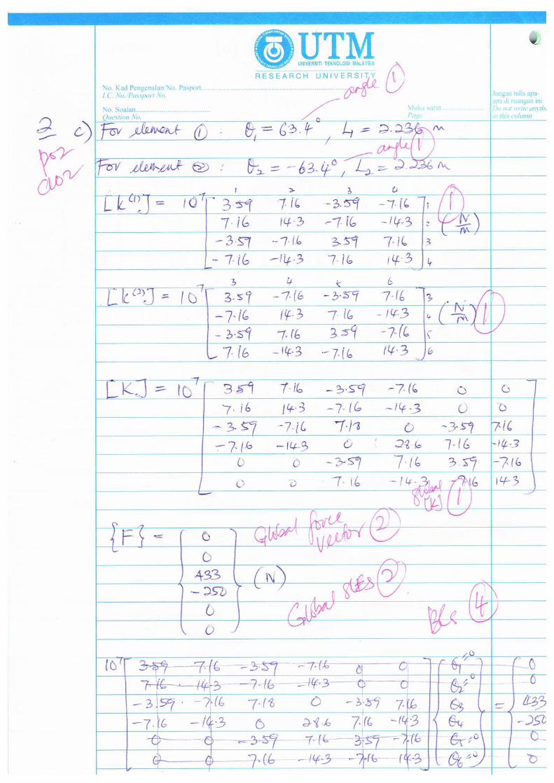
lanar truss s
N is applied
= 200 GPa) a
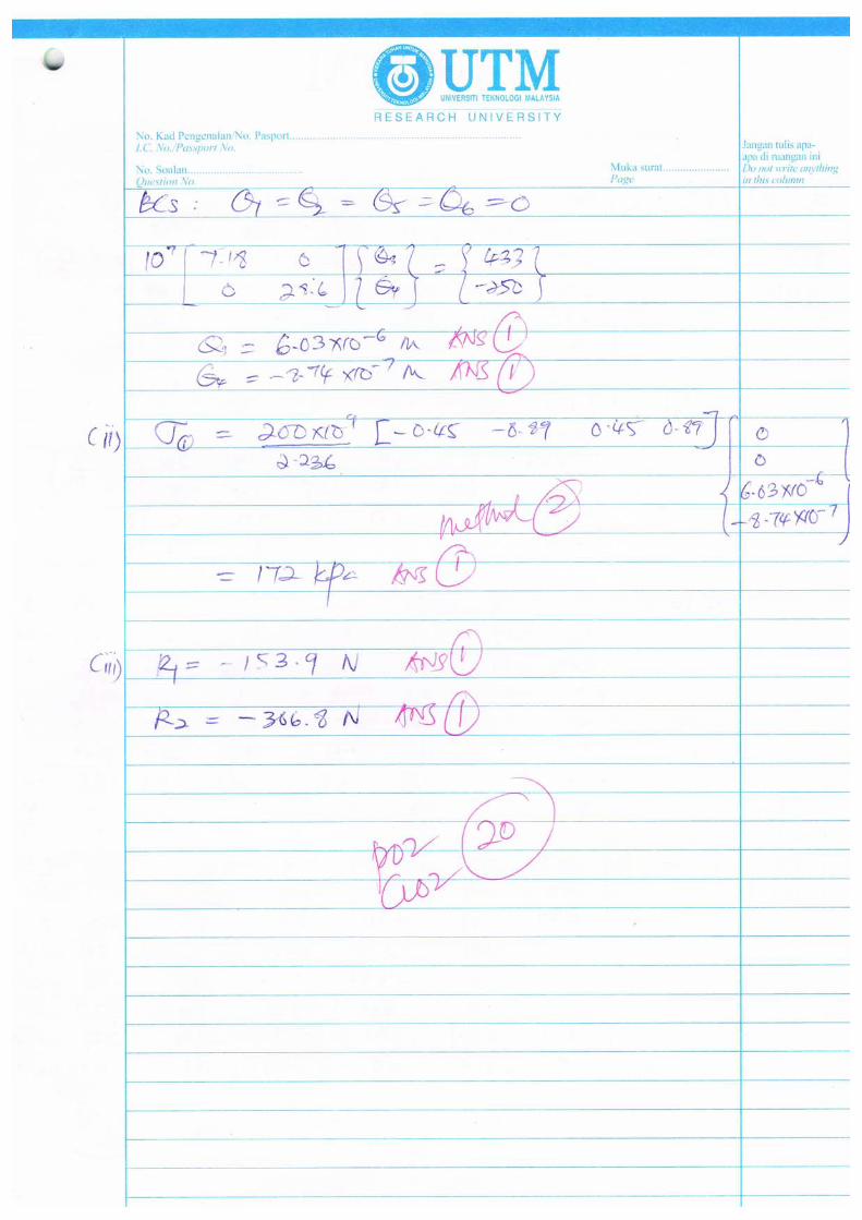
nectivity, cal
ements of no
stress in elem
n forces at no
ristics of a tw
nce between
structure has
d to the truss
and has a cr
culate the:
de 2,
ment 1,
ode 1.
ELEMENT1 2
y
-3- (SME303
wo-dimensio
n a plane trus
s the geome
at node 2, in
ross-sectiona
T 1st NOD1 2
Figure Q
x
3)
onal plane tru
ss and a plane
try as show
n the directio
al area of 20
E 2nd NOD2 3
Q2
uss structure.
e frame struc
n in Figure
on shown. E
00 mm2. By
DE
. [3
ctures? [2
Q2. A conc
Each member
y using the f
[2
3 marks]
2 marks]
centrated
r is made
following
20 marks]
-4- (SME3033)
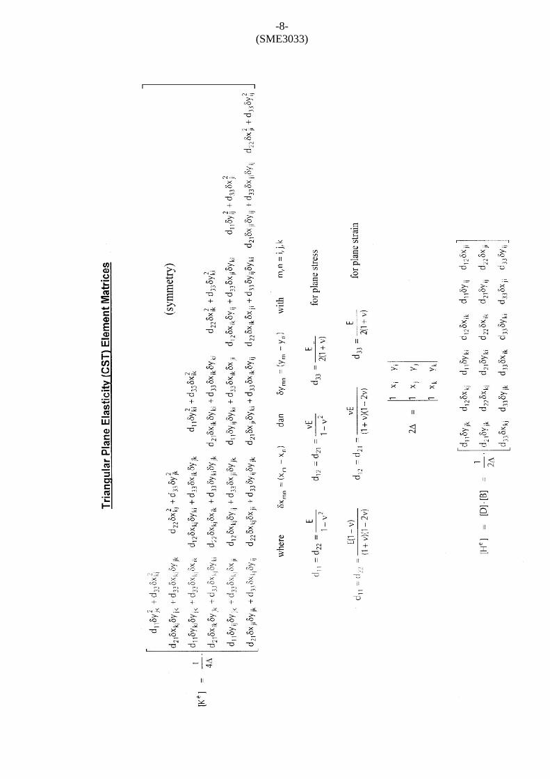
QUESTION 3 [25 marks]
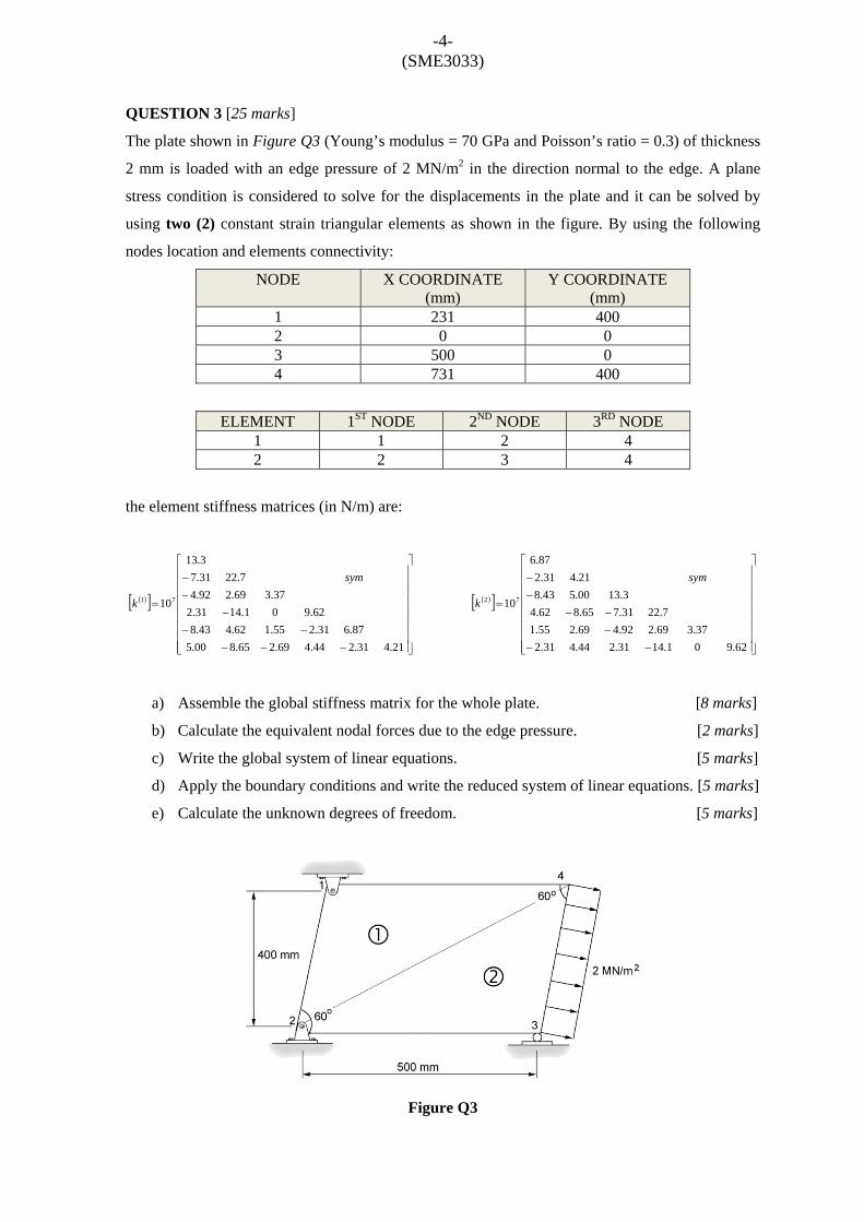
The plate shown in Figure Q3 (Young’s modulus = 70 GPa and Poisson’s ratio = 0.3) of thickness
2 mm is loaded with an edge pressure of 2 MN/m2 in the direction normal to the edge. A plane
stress condition is considered to solve for the displacements in the plate and it can be solved by
using two (2) constant strain triangular elements as shown in the figure. By using the following
nodes location and elements connectivity:
NODE X COORDINATE (mm)
Y COORDINATE (mm)
1 231 400 2 0 0 3 500 0 4 731 400
ELEMENT 1ST NODE 2ND NODE 3RD NODE 1 1 2 4 2 2 3 4
the element stiffness matrices (in N/m) are:
( )[ ]
⎥⎥⎥⎥⎥⎥⎥⎥
⎦
⎤
⎢⎢⎢⎢⎢⎢⎢⎢
⎣
⎡
−−−−−
−−−
=
21.431.244.469.265.800.587.631.255.162.443.8
62.901.1431.237.369.292.4
7.2231.73.13
1071
sym
k
( )[ ]
⎥⎥⎥⎥⎥⎥⎥⎥
⎦
⎤
⎢⎢⎢⎢⎢⎢⎢⎢
⎣
⎡
−−−−−
−−
=
62.901.1431.244.431.237.369.292.469.255.1
7.2231.765.862.43.1300.543.8
21.431.287.6
1072
sym
k
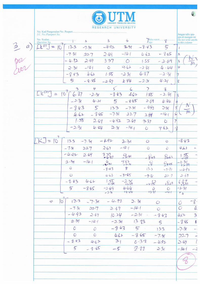
a) Assemble the global stiffness matrix for the whole plate. [8 marks]
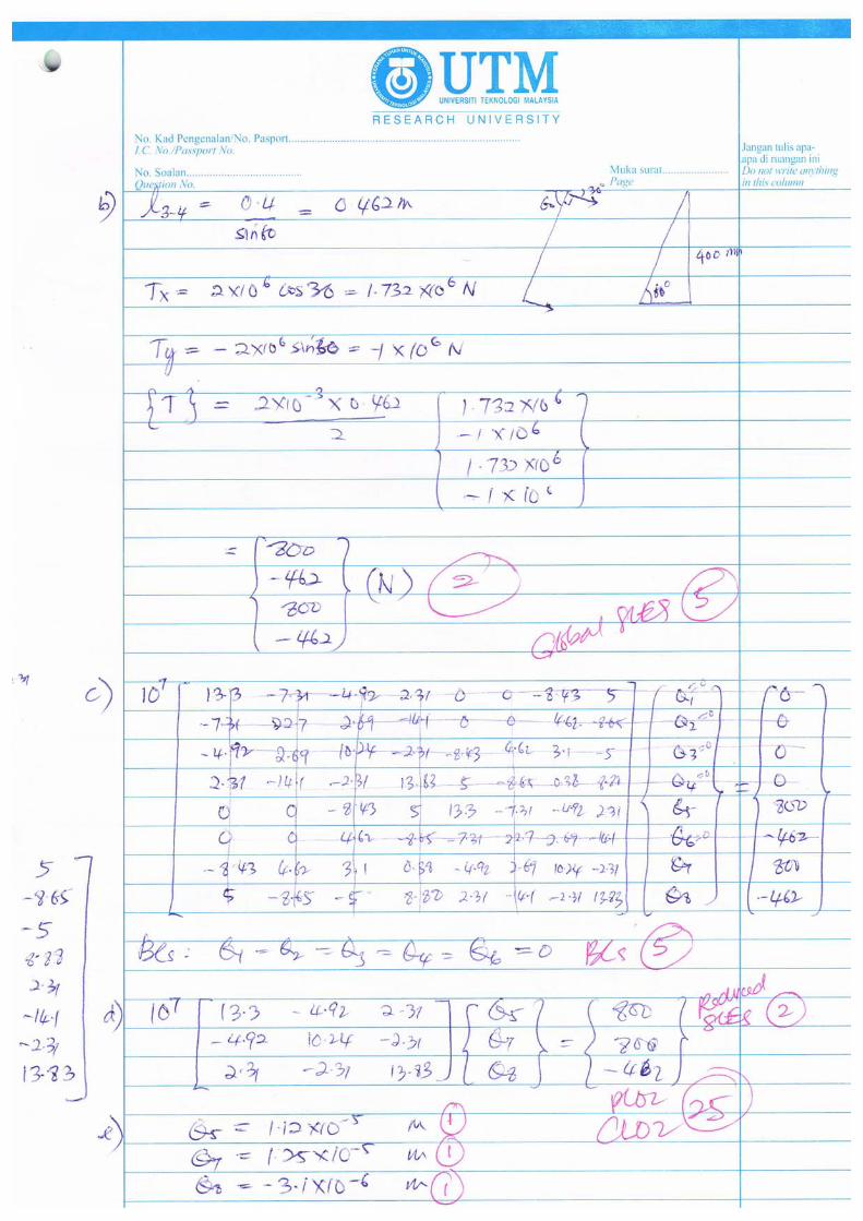
b) Calculate the equivalent nodal forces due to the edge pressure. [2 marks]
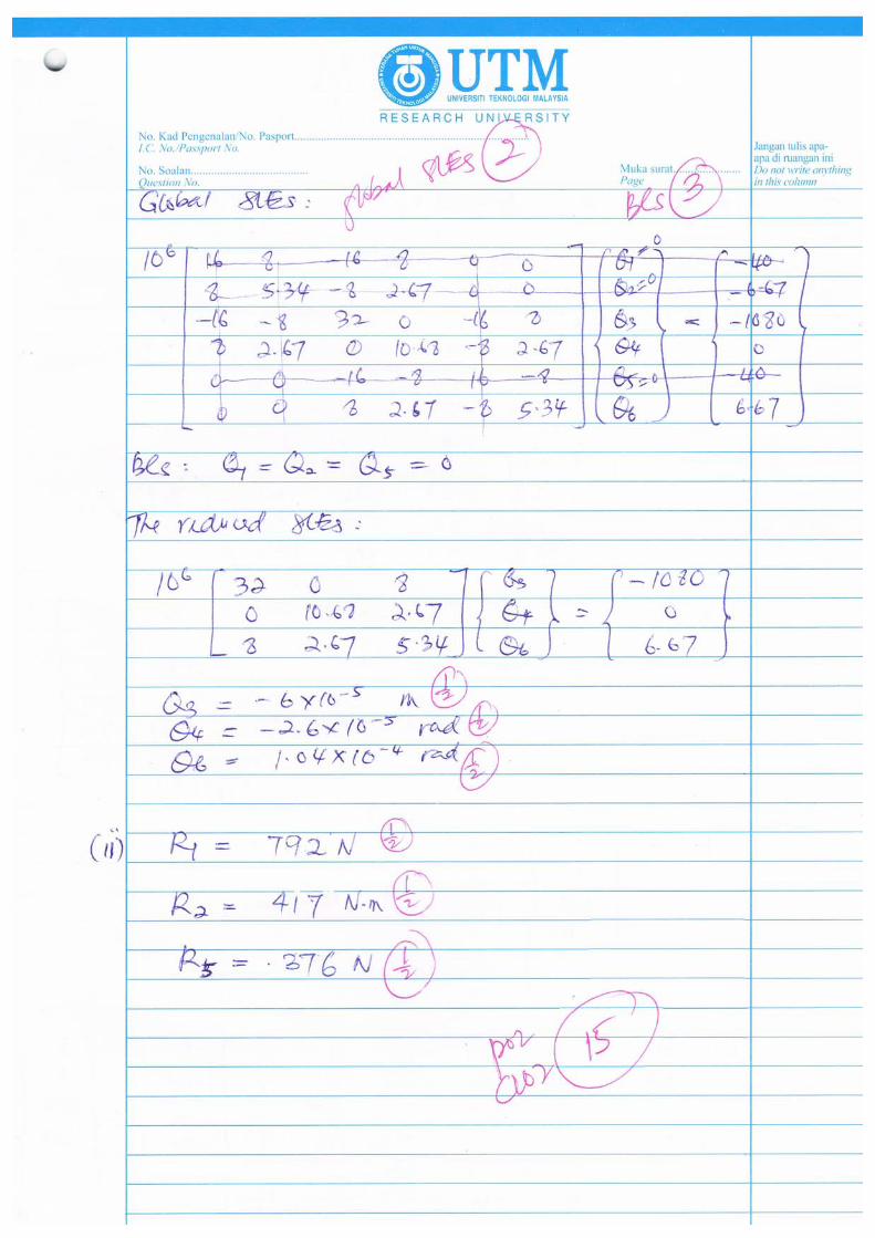
c) Write the global system of linear equations. [5 marks]
d) Apply the boundary conditions and write the reduced system of linear equations. [5 marks]
e) Calculate the unknown degrees of freedom. [5 marks]
Figure Q3
QUE
a)
b)
c)
ESTION 4 (2
What is the
Explain brie
structure?
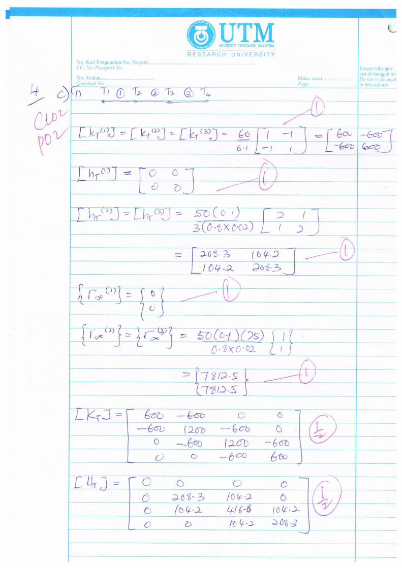
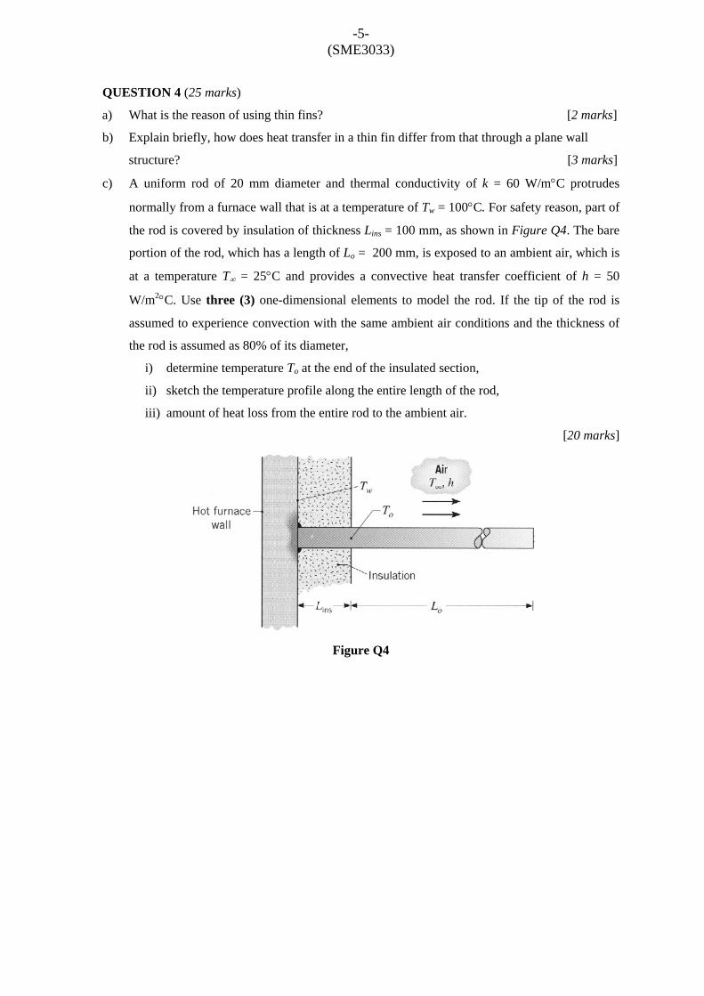
A uniform
normally fro
the rod is co
portion of th
at a temper
W/m2°C. U
assumed to
the rod is as
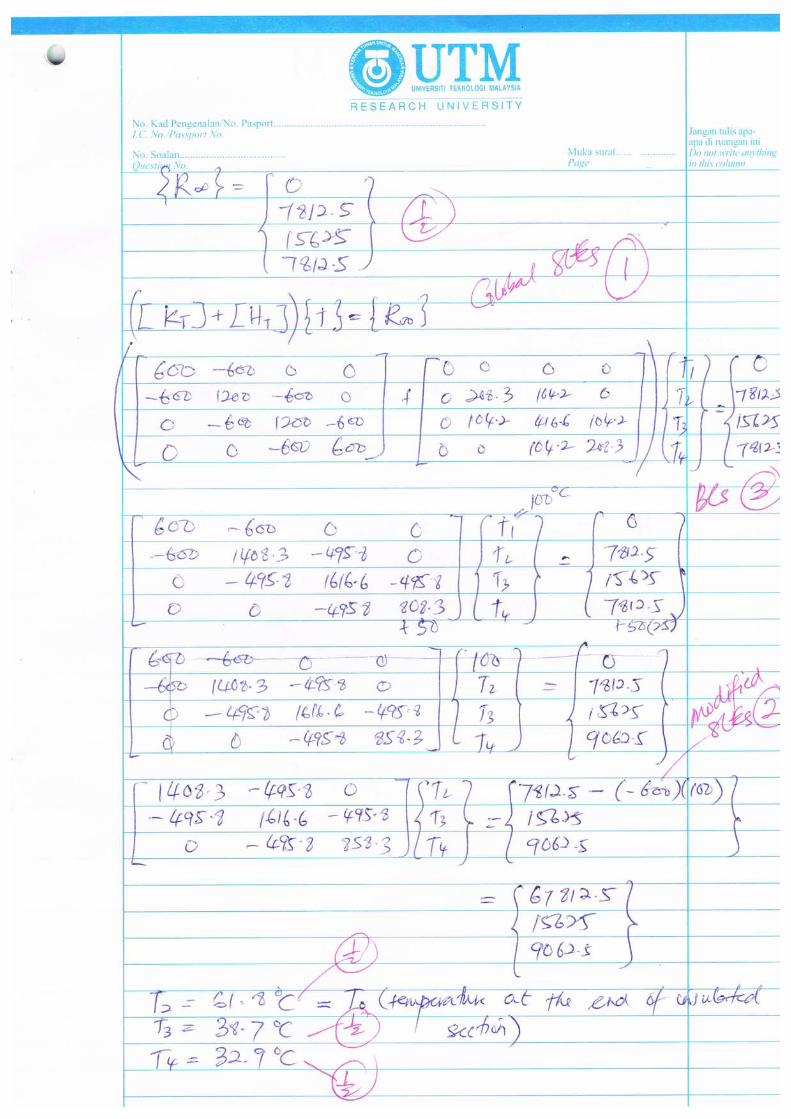
i) deter
ii) sketc
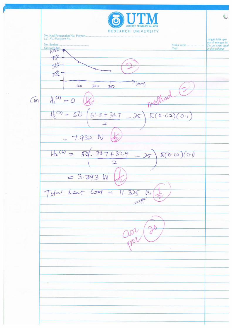
iii) amou
25 marks)
reason of us
efly, how doe
rod of 20 m
om a furnace
overed by ins
he rod, which
rature T∞ = 2
se three (3)
experience c
ssumed as 80
rmine temper
ch the temper
unt of heat lo
ing thin fins?
es heat transf
mm diameter
e wall that is
sulation of th
h has a lengt
25°C and pr
one-dimens
convection w
0% of its diam
rature To at th
rature profile
oss from the
-5- (SME303
?
fer in a thin f
r and therma
at a tempera
hickness Lins
th of Lo = 20
rovides a co
sional eleme
with the sam
meter,
he end of the
e along the e
entire rod to
Figure Q
3)
fin differ fro
al conductiv
ature of Tw =
= 100 mm,
00 mm, is ex
onvective he
nts to mode
e ambient ai
e insulated se
entire length
o the ambient
Q4
m that throu
vity of k = 6
100°C. For
as shown in
xposed to an
at transfer c
l the rod. If
ir conditions
ection,
of the rod,
t air.
[2
ugh a plane w
[3
60 W/m°C p
safety reason
Figure Q4.
ambient air,
coefficient o
f the tip of th
and the thic
[2
2 marks]
wall
3 marks]
protrudes
n, part of
The bare
which is
f h = 50
he rod is
ckness of
20 marks]
-6- (SME3033)
FORMULAE
( )
( )
( )
( )324
33
322
31
141
3241
141
3241
ξξξ
ξξ
ξξξ
ξξ
++−−=
−+=
+−−=
+−=
H
H
H
H
( ) 44332211 22qHlqHqHlqHv ee +++=ξ
( ) ( )[ ]43212 136136 qlqqlqlEIM ee
e
++−−+= ξξξξ
[ ]43213 226 qlqqlqlEIV eee
+−+=
________________________________________________________________________
[ ]⎪⎪⎭
⎪⎪⎬
⎫
⎪⎪⎩
⎪⎪⎨
⎧
−−=
4
3
2
1
qqqq
mlmllE
e
σ
[ ]2 2
3
2 2
12 6 12 66 4 6 212 6 12 6
6 2 6 4
e e
e e e e e
e ee
e e e e
l ll l l lEIk
l lll l l l
−⎡ ⎤⎢ ⎥−⎢ ⎥=⎢ ⎥− − −⎢ ⎥−⎣ ⎦
{ }2 2
2 12 2 12
Te e e e epl pl pl plf
⎡ ⎤= −⎢ ⎥⎣ ⎦
[ ] [ ]
2 2
2 2
2 2
2 2
trusse
l lm l lmlm m lm mAEk k
l l lm l lmlm m lm m
⎡ ⎤− −⎢ ⎥− −⎢ ⎥= =⎢ ⎥− −⎢ ⎥− −⎢ ⎥⎣ ⎦
-7- (SME3033)
[ ] [ ] [ ][ ]BDBAtk Tee
e = 634221
533211
qNqNqNvqNqNqNu
++=++=
[ ]JAe det21
=
ηξηξ −−=== 1321 NNN
[ ] [ ]⎥⎥⎥
⎦
⎤
⎢⎢⎢
⎣
⎡=
122131132332
211332
123123
000000
det1
yxyxyxxxx
yyy
JB
32313
32313
yyyyxxxx
++=++=
ηξηξ
[ ] ⎥⎦
⎤⎢⎣
⎡=
2323
1313
yxyx
J
[ ] 13232313det yxyxJ −=
[ ]( )
1000101
121
2
⎥⎥⎥
⎦
⎤
⎢⎢⎢
⎣
⎡
−−
=ν
νν
νED
{ } ( ) ( ) ( ) ( )[ ]Tyxyxee TTTTltT2
21−=
[ ] ( )( )
( )( )
( )
000101
21121 ⎥
⎥⎥
⎦
⎤
⎢⎢⎢
⎣
⎡
−−
−
−+=
ννν
νν
ννED
{ } [ ][ ]{ } [ ]Txyyxe qBD τσσσ ==
________________________________________________________________________
[ ] 1 11 1
eT
e
kkl
−⎡ ⎤= ⎢ ⎥−⎣ ⎦
[ ] 2 11 23
eT
hlht⎡ ⎤
≈ ⎢ ⎥⎣ ⎦
{ } 11
ehT lrt∞
∞
⎧ ⎫≈ ⎨ ⎬
⎩ ⎭
[ ] [ ]( ){ } { }e e e eT Tk h T r∞+ =
( )e avg sH h T T A∞= −
-8- (SME3033)