Volumetric Calculations - kau.edu.sa · PDF file4 5) Oil reserve by full water drive i.e. RF =...
9
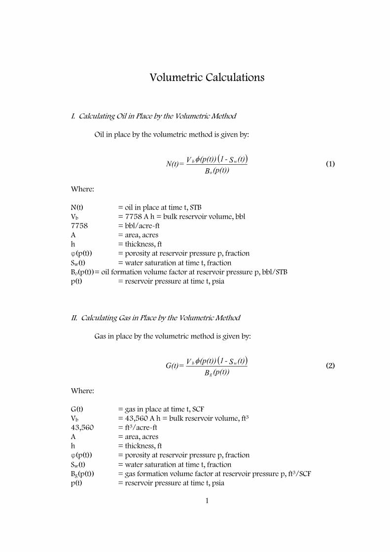
1 Volumetric Calculations I. Calculating Oil in Place by the Volumetric Method Oil in place by the volumetric method is given by: Where: N(t) = oil in place at time t, STB V b = 7758 A h = bulk reservoir volume, bbl 7758 = bbl/acre-ft A = area, acres h = thickness, ft φ(p(t)) = porosity at reservoir pressure p, fraction S w (t) = water saturation at time t, fraction B o (p(t))= oil formation volume factor at reservoir pressure p, bbl/STB p(t) = reservoir pressure at time t, psia II. Calculating Gas in Place by the Volumetric Method Gas in place by the volumetric method is given by: Where: G(t) = gas in place at time t, SCF V b = 43,560 A h = bulk reservoir volume, ft 3 43,560 = ft 3 /acre-ft A = area, acres h = thickness, ft φ(p(t)) = porosity at reservoir pressure p, fraction S w (t) = water saturation at time t, fraction B g (p(t)) = gas formation volume factor at reservoir pressure p, ft 3 /SCF p(t) = reservoir pressure at time t, psia ( ) (p(t)) B (t) S - 1 (p(t)) V = N(t) o w b φ (1) ( ) (p(t)) B (t) S - 1 (p(t)) V = G(t) g w b φ (2)
Transcript of Volumetric Calculations - kau.edu.sa · PDF file4 5) Oil reserve by full water drive i.e. RF =...
1
Volumetric Calculations I. Calculating Oil in Place by the Volumetric Method Oil in place by the volumetric method is given by:
Where: N(t) = oil in place at time t, STB Vb = 7758 A h = bulk reservoir volume, bbl 7758 = bbl/acre-ft A = area, acres h = thickness, ft φ(p(t)) = porosity at reservoir pressure p, fraction Sw(t) = water saturation at time t, fraction Bo(p(t)) = oil formation volume factor at reservoir pressure p, bbl/STB p(t) = reservoir pressure at time t, psia II. Calculating Gas in Place by the Volumetric Method Gas in place by the volumetric method is given by:
Where: G(t) = gas in place at time t, SCF Vb = 43,560 A h = bulk reservoir volume, ft3 43,560 = ft3/acre-ft A = area, acres h = thickness, ft φ(p(t)) = porosity at reservoir pressure p, fraction Sw(t) = water saturation at time t, fraction Bg(p(t)) = gas formation volume factor at reservoir pressure p, ft3/SCF p(t) = reservoir pressure at time t, psia
( )
(p(t))B(t)S - 1 (p(t)) V = N(t)
o
wbφ (1)
( )
(p(t))B(t)S - 1 (p(t)) V = G(t)
g
wbφ (2)
2
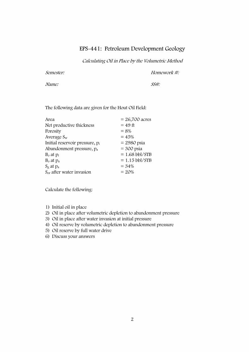
EPS-441: Petroleum Development Geology Calculating Oil in Place by the Volumetric Method Semester: Homework #: Name: SS#: The following data are given for the Hout Oil Field: Area = 26,700 acres Net productive thickness = 49 ft Porosity = 8% Average Sw = 45% Initial reservoir pressure, pi = 2980 psia Abandonment pressure, pa = 300 psia Bo at pi = 1.68 bbl/STB Bo at pa = 1.15 bbl/STB Sg at pa = 34% Sor after water invasion = 20% Calculate the following: 1) Initial oil in place 2) Oil in place after volumetric depletion to abandonment pressure 3) Oil in place after water invasion at initial pressure 4) Oil reserve by volumetric depletion to abandonment pressure 5) Oil reserve by full water drive 6) Discuss your answers
3
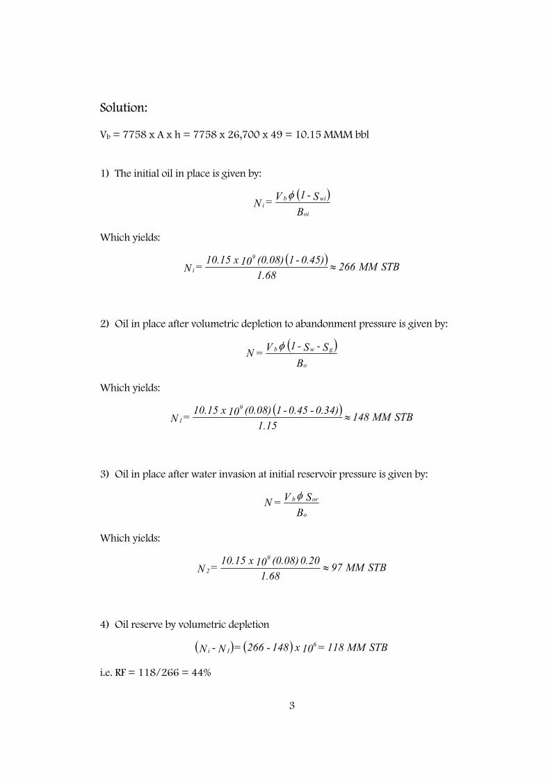
Solution: Vb = 7758 x A x h = 7758 x 26,700 x 49 = 10.15 MMM bbl 1) The initial oil in place is given by:
Which yields:
2) Oil in place after volumetric depletion to abandonment pressure is given by:
Which yields:
3) Oil in place after water invasion at initial reservoir pressure is given by:
Which yields:
4) Oil reserve by volumetric depletion
i.e. RF = 118/266 = 44%
( )B
S - 1 V = Noi
wibi
φ
( ) STBMM 266
1.680.45) - 1 (0.08) 10 x 10.15 = N
9
i ≈
( )
BS - S - 1 V = N
o
gwbφ
( ) STBMM 148
1.150.34) - 0.45 - 1 (0.08) 10 x 10.15 = N
9
1 ≈
B
S V = No
orbφ
STBMM 97 1.68
0.20 (0.08) 10 x 10.15 = N9
2 ≈
( ) ( ) STBMM 118 = 10 x 148 - 266 = N-N 61i
4
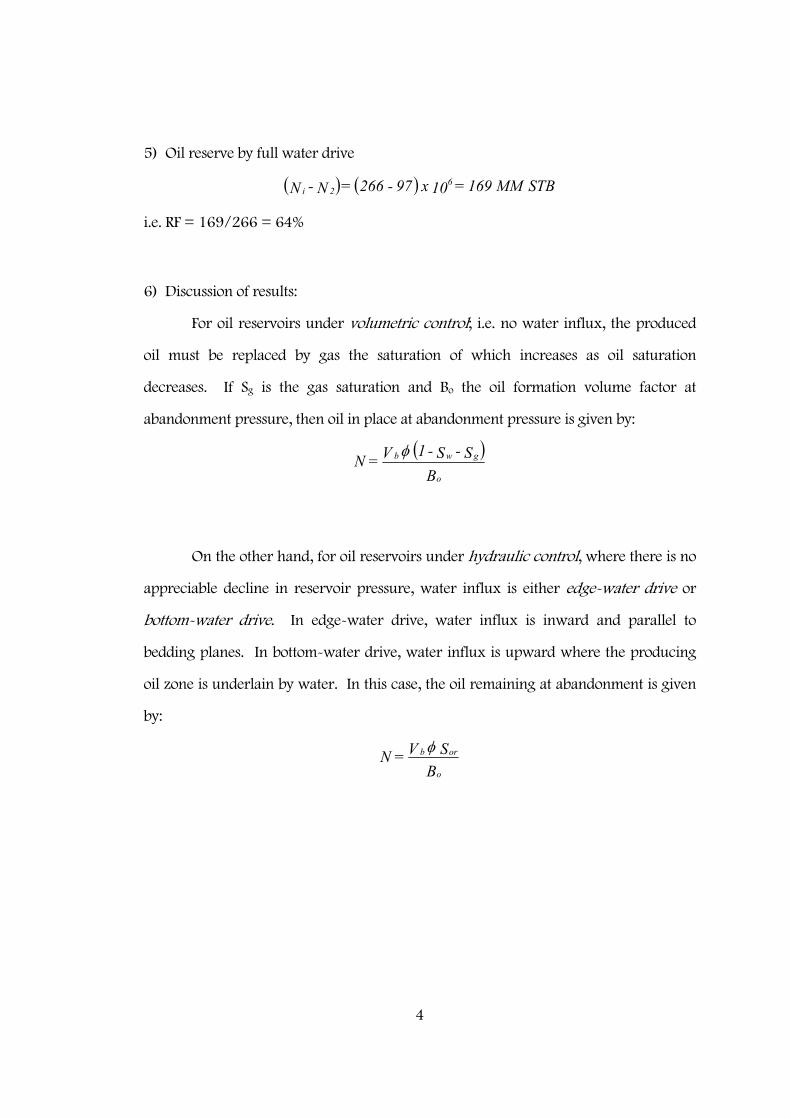
5) Oil reserve by full water drive
i.e. RF = 169/266 = 64%
6) Discussion of results:
For oil reservoirs under volumetric control; i.e. no water influx, the produced
oil must be replaced by gas the saturation of which increases as oil saturation
decreases. If Sg is the gas saturation and Bo the oil formation volume factor at
abandonment pressure, then oil in place at abandonment pressure is given by:
On the other hand, for oil reservoirs under hydraulic control, where there is no
appreciable decline in reservoir pressure, water influx is either edge-water drive or
bottom-water drive. In edge-water drive, water influx is inward and parallel to
bedding planes. In bottom-water drive, water influx is upward where the producing
oil zone is underlain by water. In this case, the oil remaining at abandonment is given
by:
( ) ( ) STBMM 169 = 10 x 97 - 266 = N-N 62i
( )
BS - S - 1 V = N
o
gwbφ
B
S V = No
orbφ
5
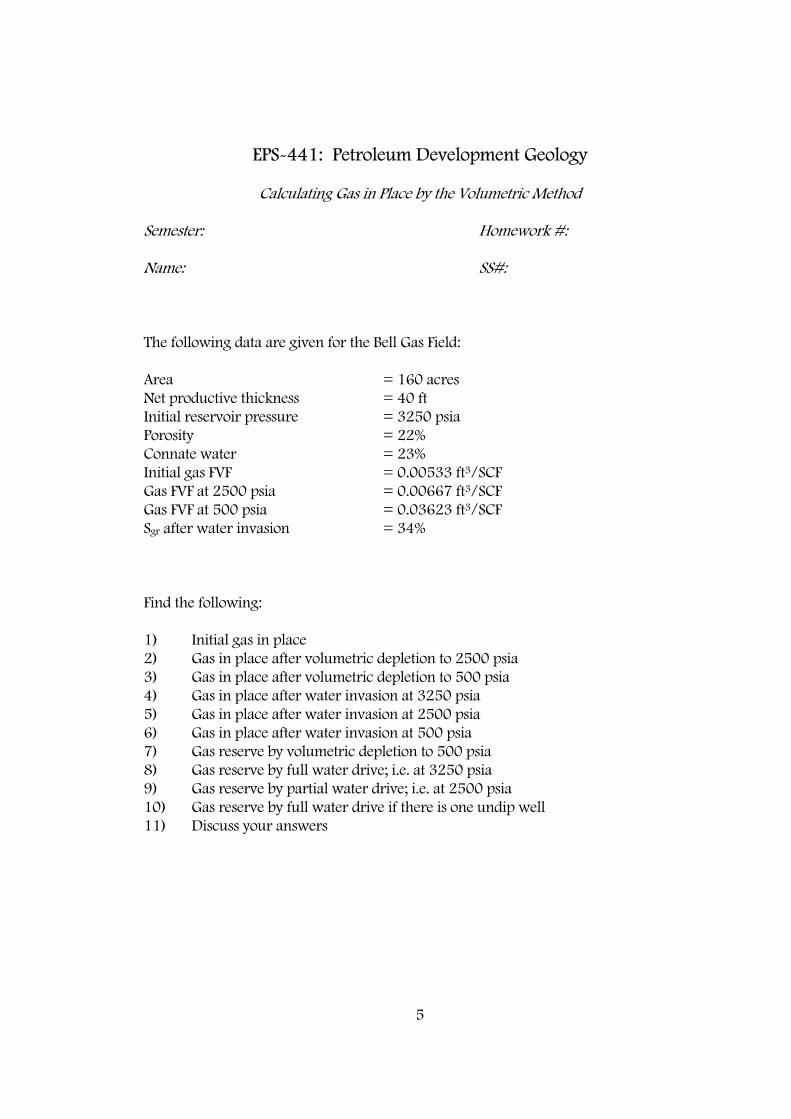
EPS-441: Petroleum Development Geology Calculating Gas in Place by the Volumetric Method Semester: Homework #: Name: SS#: The following data are given for the Bell Gas Field: Area = 160 acres Net productive thickness = 40 ft Initial reservoir pressure = 3250 psia Porosity = 22% Connate water = 23% Initial gas FVF = 0.00533 ft3/SCF Gas FVF at 2500 psia = 0.00667 ft3/SCF Gas FVF at 500 psia = 0.03623 ft3/SCF Sgr after water invasion = 34% Find the following: 1) Initial gas in place 2) Gas in place after volumetric depletion to 2500 psia 3) Gas in place after volumetric depletion to 500 psia 4) Gas in place after water invasion at 3250 psia 5) Gas in place after water invasion at 2500 psia 6) Gas in place after water invasion at 500 psia 7) Gas reserve by volumetric depletion to 500 psia 8) Gas reserve by full water drive; i.e. at 3250 psia 9) Gas reserve by partial water drive; i.e. at 2500 psia 10) Gas reserve by full water drive if there is one undip well 11) Discuss your answers
6
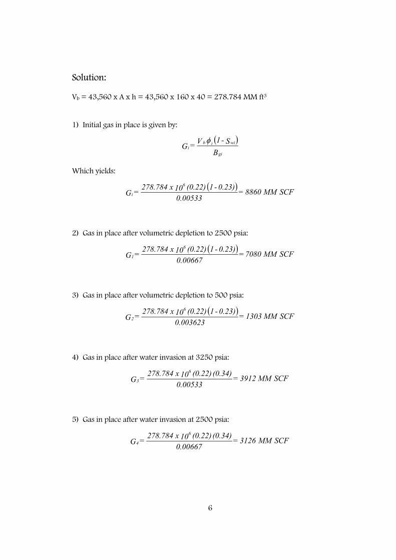
Solution: Vb = 43,560 x A x h = 43,560 x 160 x 40 = 278.784 MM ft3 1) Initial gas in place is given by:
Which yields:
2) Gas in place after volumetric depletion to 2500 psia:
3) Gas in place after volumetric depletion to 500 psia:
4) Gas in place after water invasion at 3250 psia:
5) Gas in place after water invasion at 2500 psia:
( )B
S - 1 V = Ggi
wiibi
φ
( ) SCFMM 8860 =
0.005330.23) - 1 (0.22) 10 x 278.784 = G
6
i
( ) SCFMM 7080 =
0.006670.23) - 1 (0.22) 10 x 278.784 = G
6
1
( ) SCFMM 1303 =
0.0036230.23) - 1 (0.22) 10 x 278.784 = G
6
2
SCFMM 3912 = 0.00533
(0.34) (0.22) 10 x 278.784 = G6
3
SCFMM 3126 = 0.00667
(0.34) (0.22) 10 x 278.784 = G6
4
7
6) Gas in place after water invasion at 500 psia:
7) Gas reserve by volumetric depletion to 500 psia:
i.e. RF = 7557/8860 = 85% 8) Gas reserve by water drive at 3250 psia (full water drive):
i.e. RF = 4948/8860 = 56% 9) Gas reserve by water drive at 2500 psia (partial water drive):
i.e. RF = 5734/8860 = 65% 10) Gas reserve by water drive at 3250 psia if there is one undip well:
i.e. RF = 2474/8860 = 28%
SCFMM 576 = 0.03623
(0.34) (0.22) 10 x 278.784 = G6
5
( ) SCFMM 7557 = 10 x 1303 - 8860 = G - G 62i
( ) SCFMM 4948 = 10 x 3912 - 8860 = G - G 63i
( ) SCFMM 5734 = 10 x 3126 - 8860 = G - G 64i
( ) ( ) SCFMM 2474 = 10 x 3912 - 8860 21 = G - G
21 6
3i
8
12) Discussion of results:
The RF for volumetric depletion to 500 psia (no water drive) is calculated to be
85%. On the other hand, the RF for partial water drive is 65%, and for the full water
drive is 56%. This can be explained as follows: As water invades the reservoir,
reservoir pressure is maintained at a higher level than if there were no water
encroachment. This leads to higher abandonment pressures for water-drive reservoirs.
Recoveries, however, are lower because the main mechanism of production in gas
reservoirs is depletion or gas expansion.
In water-drive gas reservoirs, it has been found that gas recoveries can be
increased by:
1) Outrunning technique: Which is accomplished by increasing gas production rates.
This technique has been attempted in Bierwang Field in West Germany where the field
production rate has been increased from 50 to 75 MM SCF/D, and they found that the
ultimate recovery increased from 69 to 74%.
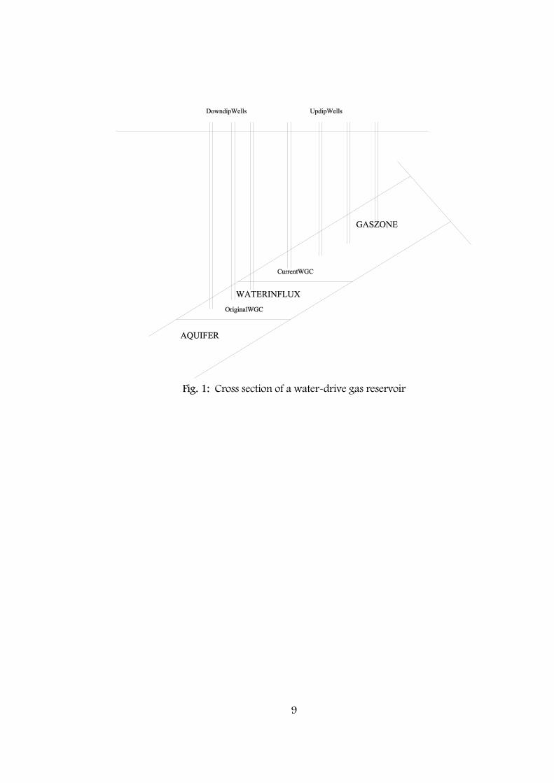
2) Coproduction technique: This technique is defined as the simultaneous production
of gas and water, see Fig. 1. In this process, as downdip wells begin to be watered out,
they are converted to high-rate water producers, while the updip wells are maintained
on gas production. This technique enhances production as follows:
First: the high-rate downdip water producers act as a pressure sink for the water. This
retards water invasion into the gas zone, therefore prolonging its productive life.
Second: the high-rate water production lowers the average reservoir pressure,
allowing for more gas expansion and therefore more gas production.
Third: when the average reservoir pressure is lowered, the immobile gas in the water-
swept portion of the reservoir could become mobile and hence producible.
It has been reported that this technique has increased gas production from 62%
to 83% in Eugene Island Field of Louisiana.
9
Fig. 1: Cross section of a water-drive gas reservoir