M80 Oil Pump Manual
24
-
Upload
elliot-smith -
Category
Documents
-
view
174 -
download
26
description
mycom m80 oil pump maual
Transcript of M80 Oil Pump Manual
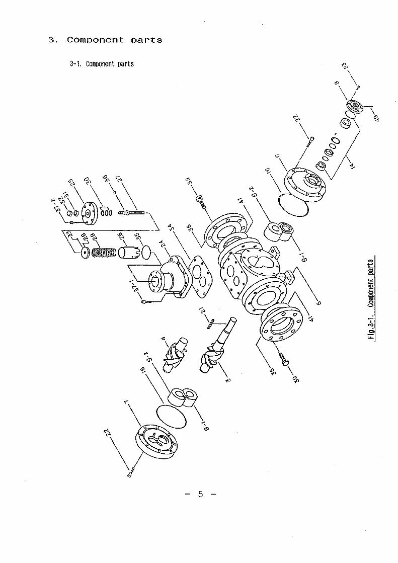
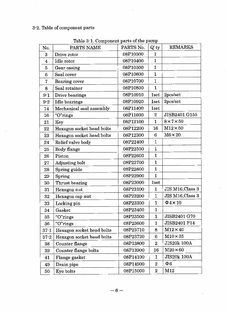
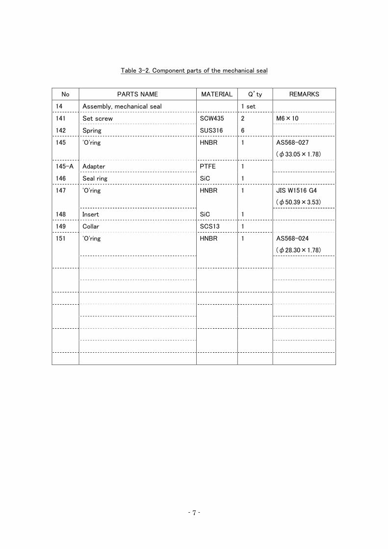
Table 3-2. Component parts of the mechanical seal
No PARTS NAME MATERIAL Q’ty REMARKS
14 Assembly, mechanical seal 1 set
141 Set screw SCW435 2 M6×10
142 Spring SUS316 6
145 'O'ring HNBR 1 AS568-027
(φ33.05×1.78)
145-A Adapter PTFE 1
146 Seal ring SiC 1
147 'O'ring HNBR 1 JIS W1516 G4
(φ50.39×3.53)
148 Insert SiC 1
149 Collar SCS13 1
151 'O'ring HNBR 1 AS568-024
(φ28.30×1.78)
- 7 -
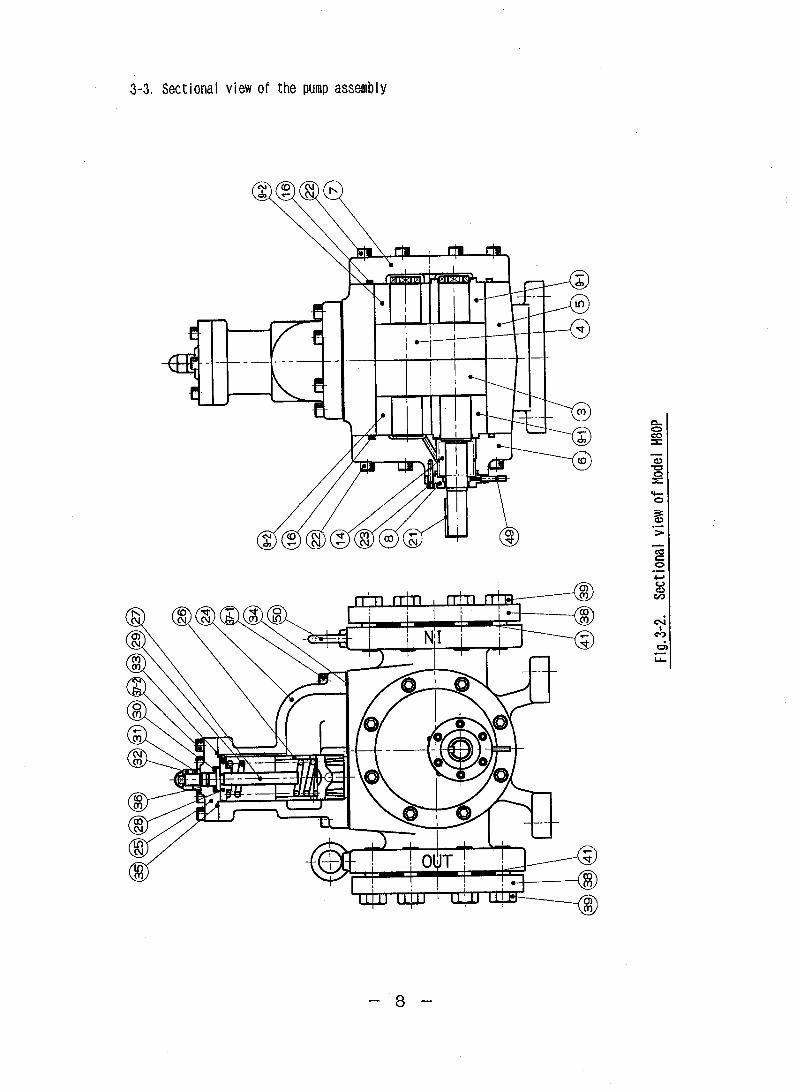
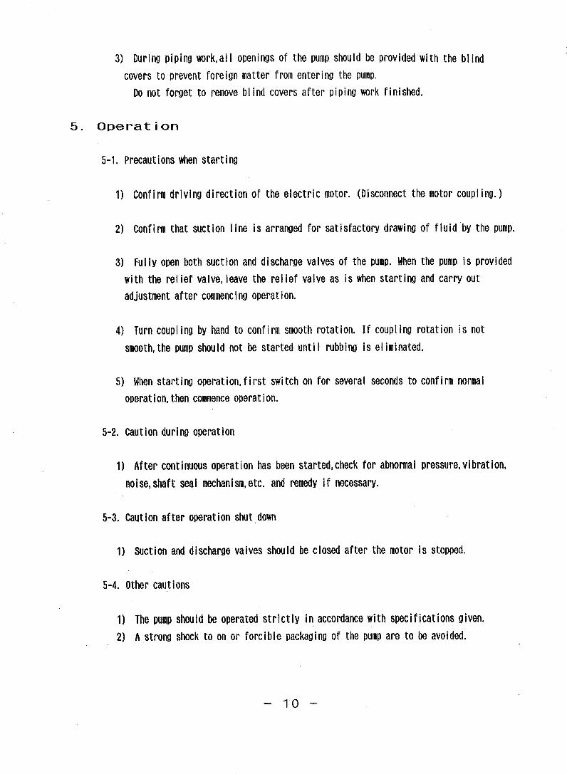
8. Disassembly/assembly
8-1. Disassembly of the pump
Disconnect the coupling. Remove the pump from the common base. Loose the set screw on
the coupling. Draw the coupling out of the shaft.
1) Remove the relief valve from the pump, if there are.
2) Remove the seal retainer(8) from the seal cover(6).
3) Remove the seal cover(6) from the gear casing(5).
4) Loose the set screw(141) of the collar(149).
5) Remove the mechanical seal(14) from the drive rotor(3).
8) Remove the blind cover(7) from the gear casing(5).
7) Draw the rotors(3 and 4) from the blind cover side of the gear casing(5).
*1 If it is difficult, tap the shaft end softly with a plastic mallet.
*2 The bearings(9-1 and 9-2) at the blind cover side draw with the rotors(3 and 4).
*3 If temperature of bearings exceeds 30℃, do not remove until temperature drops below 30℃
*4 Drive rotor and idle rotor cannot be disassembled.
8) Draw the bearings(9-1 and 9-2) at the seal cover side from the gear casing(5).
8-2. Assembly of the pump
Clean the all parts listed in table 3-1,and arrange them on a clean and dry cloth.
1) Fit the interlocking marks of the drive rotor(3) and the idle rotor(4), and interlock the rotors.
2) Insert the rotors(3 and 4) into the blind cover side of the gear casing(5).
3) Coat the all surfaces of bearing with oil.
4) Point the groove of the bearing(9-1 and 9-2) to the discharge side, and mount the bearings to the
rotors(3 and 4).
5) Coat the blind cover(7) and the 'O'ring(16) with oil.
6) Set the 'Oring(16) to the blind cover(7).
7) Install the blind cover(7) to the gear casing(5).
- 16 -
8) Assemble the mechanical seal assembly(14), the seal cover(6) and the seal retainer(8).
Refer to details of 8-5, procedure of the mechanical seal assembly.
9) In case the pump has the relief valve(24), install the relief valve to the gear casing(5). If not so,
install the blind plate(50) to the gear casing(5).
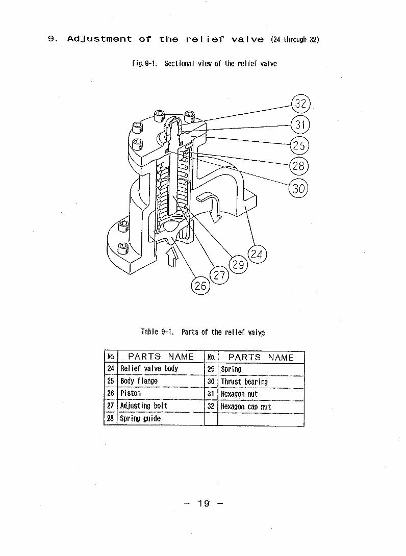
8-3. Disassembly of the relief valve
Remove the relief valve(24) from the pump.
1) Remove the hexagon cap nut(32).
2) Loose the relief valve adjusting bolt(27) by turning counterclockwise fully.
3) Remove the hexagon nut(31).
4) Draw the hexagon socket head bolts(37-2).
5) Remove the relief valve flange(25) with the relief valve adjusting bolt(27) and the spring
guide(28).
6) Draw the relief valve adjusting bolt(27) with the 'O'ring(36) from the relief valve flange(25).
7) Remove the spring guide(28) by turning clockwise.
8) Draw the spring(29) and the piston(26) from the relief valve(24).
8-4. Assembly of the relief valve
Arrange the parts listed in No.24~37-2 of table 3-1 on a clean and dry cloth.
1) Coat the piston(26) with oil.
2) Insert the piston(26) and the spring(29) to the relief valve(24).
3) Mount the 'O'ring(36) to the relief valve adjusting bolt(27).
4) Insert the relief valve adjusting bolt(27) to the relief valve flange(25).
5) Screw the spring guide(28) to the relief valve adjusting bolt(27).
6) Coat the 'O'ring(35) with oil.
7) Set the 'O'ring(35) in the relief valve flange(25).
8) Install the relief valve flange(25) to the relief valve(24).
* Point the locking pin(33) into the groove of the relief valve(24).
- 17 -
9) Screw the hexagon cap nut(32)
*Install the relief valve to the pump in exactly direction.
For oil pressure adjustment of the relief valve, refer to page 19~20.
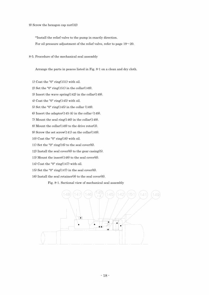
8-5. Procedure of the mechanical seal assembly
Arrange the parts in peaces listed in Fig. 8-1 on a clean and dry cloth.
1) Coat the "0" ring(151) with oil.
2) Set the "0" ring(151) in the collar(149).
3) Insert the wave spring(142) in the collar(149).
4) Coat the "0" ring(145) with oil.
5) Set the "0" ring(145) in the collar (149).
6) Insert the adapter(145-A) in the collar (149).
7) Mount the seal ring(146) in the collar(149).
8) Mount the collar(149) to the drive rotor(3).
9) Screw the set screw(141) on the collar(149).
10) Coat the "0" ring(16) with oil.
11) Set the "0" ring(16) to the seal cover(6).
12) Install the seal cover(6) to the gear casing(5).
13) Mount the insert(148) to the seal cover(6).
14) Coat the "0" ring(147) with oil.
15) Set the "0" ring(147) in the seal cover(6).
16) Install the seal retainer(8) to the seal cover(6).
Fig. 8-1. Sectional view of mechanical seal assembly
- 18 -
Before operating, maintaining, or inspecting this product, read the manual
thoroughly and fully understand the contents.
Keep the operation manual in a safe, designated place for future reference
whenever the need arises.
Specifications of this product are subject to change without prior notice.
27.APR.2012