U.S. Muon - Fermilab · Web viewDesign work on the PRY extension for Step 3π/2 will begin as...
27
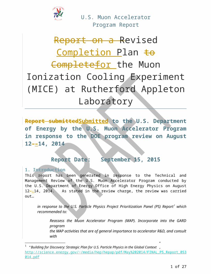
U.S. Muon Accelerator Program Report Report on a Revised Completion Plan to Complete for the Muon Ionization Cooling Experiment (MICE) at Rutherford Appleton Laboratory Report submitted Submitted to the U.S. Department of Energy by the U.S. Muon Accelerator Program in response to the DOE program review on August 12- – 14, 2014 Report Date: September 15, 2015 1. Introduction This report has been generated in response to the Technical and Management Review of the U.S. Muon Accelerator Program conducted by the U.S. Department of Energy Office of High Energy Physics on August 12- – 14, 2014. As stated in the review charge, the review was carried out… in response to the U.S. Particle Physics Project Prioritization Panel (PS) Report 1 which recommended to: Reassess the Muon Accelerator Program (MAP). Incorporate into the GARD program the MAP activities that are of general importance to accelerator R&D, and consult with 1 “Building for Discovery: Strategic Plan for U.S. Particle Physics in the Global Context ”, http://science.energy.gov/~/media/hep/hepap/pdf/May%202014/FINAL_P5_Report_053 014.pdf 1 of 27
Transcript of U.S. Muon - Fermilab · Web viewDesign work on the PRY extension for Step 3π/2 will begin as...
U.S. Muon Accelerator Program Report
Report on a Revised Completion Plan to Complete for the Muon Ionization Cooling Experiment (MICE) at Rutherford Appleton
LaboratoryReport submittedSubmitted to the U.S. Department of Energy by the U.S. Muon Accelerator Program in response to the DOE program review on August 12-–14, 2014
Report Date: September 15, 20151. IntroductionThis report has been generated in response to the Technical and Management Review of the U.S. Muon Accelerator Program conducted by the U.S. Department of Energy Office of High Energy Physics on August 12-–14, 2014. As stated in the review charge, the review was carried out…
in response to the U.S. Particle Physics Project Prioritization Panel (PS) Report1 which recommended to:
Reassess the Muon Accelerator Program (MAP). Incorporate into the GARD programthe MAP activities that are of general importance to accelerator R&D, and consult withinternational partners on the early termination of MICE.
In particular, the panel recommends to "realign activities in accelerator R&D with the P5 strategic plan. Redirect muon collider R&D and consult with international partners on the earlytermination of the MICE muon cooling R&D facility."
A key outcome of the review was the action item:
Present to DOE a detailed plan for Step 3π/2 by 15 September 2014.
This report describes that plan, which aims for the completion of MAP-supported participation in the Muon Ionization Cooling Experiment (MICE) with a demonstration of the full cooling process, including RF re-acceleration, on the 2017 timescale. It also targets a rapid ramp-down of the other elements of the MAP research effort over the next year.
1 “Building for Discovery: Strategic Plan for U.S. Particle Physics in the Global Context”, http://science.energy.gov/~/media/hep/hepap/pdf/May%202014/FINAL_P5_Report_053014.pdf
1 of 21
U.S. Muon Accelerator Program Report
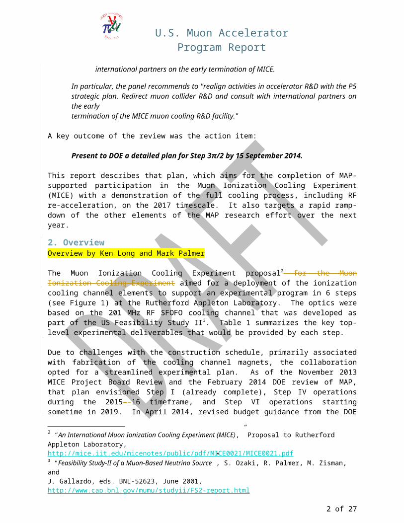
2. OverviewOverview by Ken Long and Mark Palmer
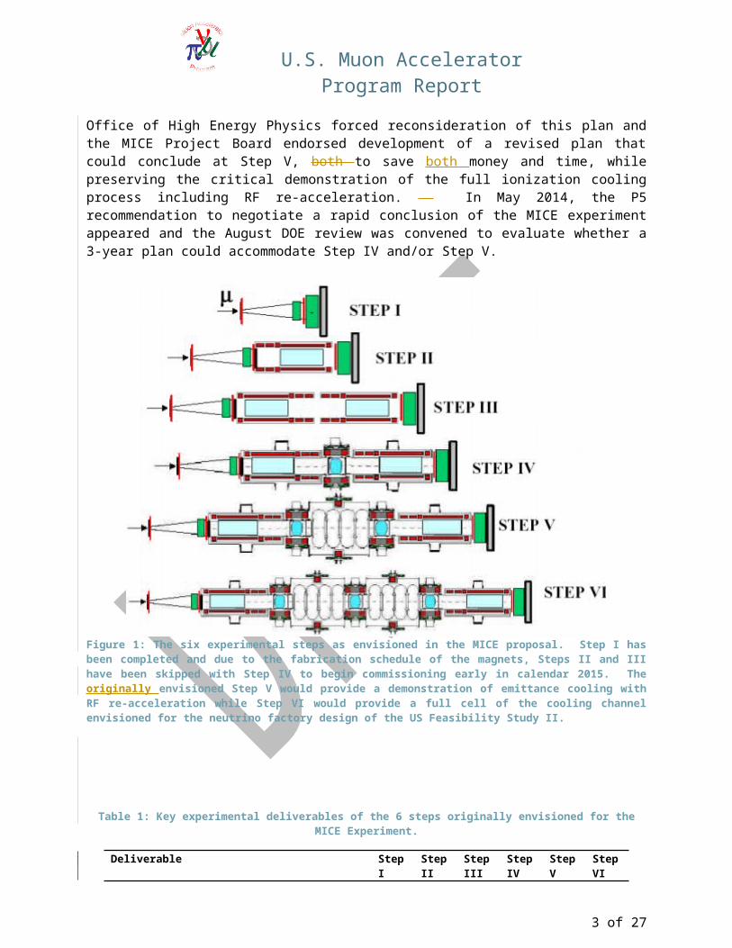
The Muon Ionization Cooling Experiment proposal2 for the Muon Ionization Cooling Experiment aimed for a deployment of the ionization cooling channel elements to support an experimental program in 6 steps (see Figure 1) at the Rutherford Appleton Laboratory. The optics were based on the 201 MHz RF SFOFO cooling channel that was developed as part of the US Feasibility Study II3. Table 1 summarizes the key top-level experimental deliverables that would be provided by each step.
Due to challenges with the construction schedule, primarily associated with fabrication of the cooling channel magnets, the collaboration opted for a streamlined experimental plan. As of the November 2013 MICE Project Board Review and the February 2014 DOE review of MAP, that plan envisioned Step I (already complete), Step IV operations during the 2015-–16 timeframe, and Step VI operations starting sometime in 2019. In April 2014, revised budget guidance from the DOE Office of High Energy Physics forced reconsideration of this plan and the MICE Project Board endorsed development of a revised plan that could conclude at Step V, both to save both money and time, while preserving the critical demonstration of the full ionization cooling process including RF re-acceleration. In May 2014, the P5 recommendation to negotiate a rapid conclusion of the MICE experiment appeared and the August DOE review was convened to evaluate whether a 3-year plan could accommodate Step IV and/or Step V.
Figure 1: The six experimental steps as envisioned in the MICE proposal. Step I has been completed and due to the fabrication schedule of the magnets, Steps II and III have been skipped with Step IV to begin commissioning early in calendar 2015. The originally envisioned Step V would provide a demonstration of emittance cooling with RF re-
2 “An International Muon Ionization Cooling Experiment (MICE),” Proposal to Rutherford Appleton Laboratory, http://mice.iit.edu/micenotes/public/pdf/MICE0021/MICE0021.pdf3 “Feasibility Study-II of a Muon-Based Neutrino Source”, S. Ozaki, R. Palmer, M. Zisman, andJ. Gallardo, eds. BNL-52623, June 2001, http://www.cap.bnl.gov/mumu/studyii/FS2-report.html
2 of 21
U.S. Muon Accelerator Program Report
acceleration while Step VI would provide a full cell of the cooling channel envisioned for the neutrino factory design of the US Feasibility Study II.
Table 1: Key experimental deliverables of the 6 steps originally envisioned for the MICE Experiment.
Deliverable Step I Step II
Step III
Step IV
Step V
Step VI
Characterization of TOF and PID systems and muon beam ✓Characterization of Spectrometer Solenoid and Tracker Performance
✓ ✓ ✓
Characterization of Cooling Channel Absorber Energy Loss and Multiple Scattering
✓
Demonstration of Emittance Cooling with RF Re-acceleration
✓
Characterization of SFOFO Cooling Channel Optics (based on Study II) with canonical momentum control and full optics flexibility
✓
The MAP position on the MICE experiment is that a demonstration of the full ionization cooling process (i.e., emittance cooling combined with RF re-acceleration) must be completed in order for a successful conclusion of MICE to be achieved. In Table 1, this corresponds to completion of Step V. However, the members of the August 2014 review committee indicated extreme skepticism that declining US support would allow this to be achieved with Step V given both the budget profile being proposed by DOE (which would severely restrict US experimental support) and the 3-year timeframe prescribed (which would likely result in very limited US laboratory support to be available for Step V operations). Finally, the committee expressed concerns that the remaining R&D risks associated with the RF-Coupling Coil (RFCC) module could be adequately managed within the 3-year timeframe. With these concerns, the MICE team at the review carried out a preliminary assessment of whether a demonstration of emittance cooling with RF re-acceleration could be provided with components already largely in hand and within the 3-year timeframe specified by the US DOE. The resulting concept has been (temporarily) labeled MICE Step 3π/2. Over the course of the last month, this concept has been evaluated in greater detail as described below.
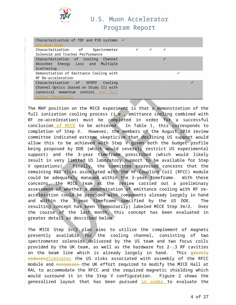
The MICE Step 3/2 plan aims to utilize the complement of magnets presently available for the cooling channel, consisting of two spectrometer solenoids delivered by the US team and two focus coils provided by the UK team, as well as the hardware for 2-–3 RF cavities on the beam line which is already largely in hand. This greatly reduceseliminates the US risks associated with assembly of the RFCC module and minimizes the UK effort required to modify the MICE Hall at RAL to accommodate the RFCC and the required magnetic shielding which would surround it in the Step V configuration. Figure 2 shows the generalized layout that has been pursued in order to evaluate the relevant beam line optics. It should be noted that this generalized configuration actually has closer resemblance to the optics being consideredof for “modern” neutrino factory cooling channel designs being considered by the IDS-NF study4 as well as by the Muon Accelerator Staging Study (MASS) within MAP. The revised configuration will require an alternative design for a Partial Return Yoke (PRY) for the beam line to be developed – a relatively straightforward engineering exercise which is significantly less expensive than that of the Step V configuration. Furthermore, additional absorbers may need to be procured in order to successfully execute the plan. The additional absorbers offer negligible project risk and budget impact.
4 IDS-NF “Interim Design Report,” http://arxiv.org/abs/1112.2853
3 of 21
U.S. Muon Accelerator Program Report
Figure 2: A generalized layout of the proposed cooling channel showing the position of the coils in each of the spectrometer solenoid and focus coil magnets. The three gaps shown provide space to match the lattice parameters for the cooling demonstration and focus coil magnets. The three gaps shown provide space to match the lattice parameters for the cooling demonstration and for inclusion of the necessary RF and absorber elements.
The following sections describe the optics and project impacts of executing this step as the conclusion of the MICE demonstration. Our evaluation indicates that a successful demonstration of the ionization cooling process can be achieved with this configuration within the timeframe mandated by the DOE budget profile for concluding the MAP effort.
3. MICE Optics SummaryOptics Summary by MICE optics team with supporting evaluations from MAP D&S TeamIn order to reduce the R&D risks associated with completion of MICE, the MICE optics team has focused on Step 3π/2 options that make use of existing designs and hardware. The upshot is that such options indeed exist and are suitable for the key MICE deliverable: the demonstration of muon ionization cooling with RF re-acceleration.
3.1 Introduction
Following the P5 recommendations the US DOE set the committee (MAP Review) to evaluate the MICE experiment at RAL and in particular its schedule for completing the proof of principle demonstration of ionization cooling of muons. One of the committee's key finding is the need to accelerate the schedule of the experiment to achieve the demonstration of sustainable cooling (with muon re-acceleration using RF cavities) in 2017 in order to fit in the current financial constraints of both main funding bodies: STFC in the UK and DOE in the US. During the Review a possible scenario called "Step 3/2" was identified, which may allow to achieve the necessary schedule acceleration by reducing the complexity of Step V by elimination of the RFCC module, in particular by dropping construction of the Coupling Coil (CC) magnet. This will allow to simultaneously preserve essential measurements at Step IV scheduled in 2015.
This report investigates the consequences of removing the RFCC module and seeks for geometries and lattices, which will allow to make the essential ionization cooling demonstration at Step 3/2.
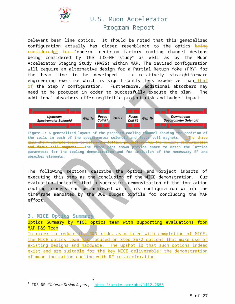
3.2 Optics in MICE Channel with and without RFCC moduleIn the original design of the Step V (shown in Figure 3), an RFCC module containing four RF cavities are is placed together between two Absorber-Focus Coil (AFC) modules each housting absorbers made of either liquid hHydrogen (LH2) or Llithium hHydride (LiH). The cavities are surrounded by the immersed in magnetic field created by the CC magnet, which immerses them in a multi-tesla magnetic fieldis surrounding the cavities forming the so called RFCC module, as is shown in Figure 3.
4 of 21
U.S. Muon Accelerator Program Report
Figure 3: The conceptual layout of MICE at Step V, consisting in particular of cluding upstream and downstream Spectrometer Solenoids (coils indicated in red), two AFCs (green) housting absorbers, and central RFCC in the middle with four RF cavities inside surrounded by the CC magnet (orange).
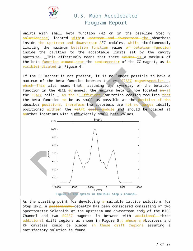
The role of the CC magnet is to allows the transverse betatron function in the solenoidal channel to be matched between the two waists with small beta function (42 cm in the baseline Step V solutioncase) located within upstream and downstream the absorbers inside the upstream and downstream AFC modules, while simultaneously limiting the maximum betatron function value of betatron function inside the cavities to the acceptable limits set by the cavity aperture. This effectively means that there exists is a maximum of the beta function around near the centrecenter of the CC magnet, as is visibleindicated in Figure 4.
If the CC magnet is not present, it is no longer possible to have a maximum of the beta function between the two FCAFC magnetsmodules. , which This also means that, assuming the symmetry of the betatron function in the MICE Cchannel, the maximum beta is now located in at the FCAFC coils. As the i Efficient ionization cooling requires that the beta function to be as small as possible at the position of the absorber positions, therefore the absorbers are not no longer ideally positioned withiin the FCAFC coils module and should be placed at another locations with sufficiently small beta values.
Figure 4: The optics in the MICE Step V Channel.
As the starting point for developing a suitable lattice solutions for Step 3/2, a preliminary geometry has been considered consisting of two Spectrometer Solenoids at the upstream and downstream ends of the MICE Channel and two FCAFC magnets in between with additional three additional drift regions as shown in Figure 5., where a Absorbers and RF cavities could be placed in these drift regions assuming a satisfactory solution is found.
5 of 21
U.S. Muon Accelerator Program Report
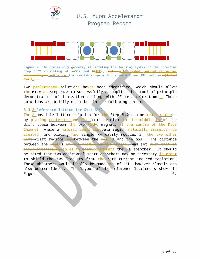
Figure 5: The preliminary geometry illustrating the focusing system of the potential Step 3π/2 consisting of SSs and FCAFCs, and with dashed rounded rectangles summarising indicating the available space for absorbers and RF cavities (dashed ovals.).
Two preliminary solutions haves been identified, which should allow the MICE at Step 3/2 to successfully accomplish the proof of principle demonstration of ionization cooling with RF re-acceleration. These solutions are briefly described in the following sections.
3.3 2 Reference lattice for Step 3/2The A possible lattice solution for the Step 3/2 can be realisrealized by placing centering one the main absorber in the middle in of the drift space between the two FCAFC magnets at the centre of the MICE Channel, where a natural small low-beta region naturally arisescan be created, and placing two single RF cavity modules in the two other left drift regions in between the FCAFCs and the SSs. The distance between the FCAFCs in the middle of the Channel was set such that it could potentially so as to hostaccommodate the LH2 absorber. It should be noted that two additional short absorbers may be necessary in order to shield the two Trackers from the dark current induced radiation. These absorbers would ideally be made out of LiH, however plastic can also be considered. The layout of the reference lattice is shown in Figure 6.
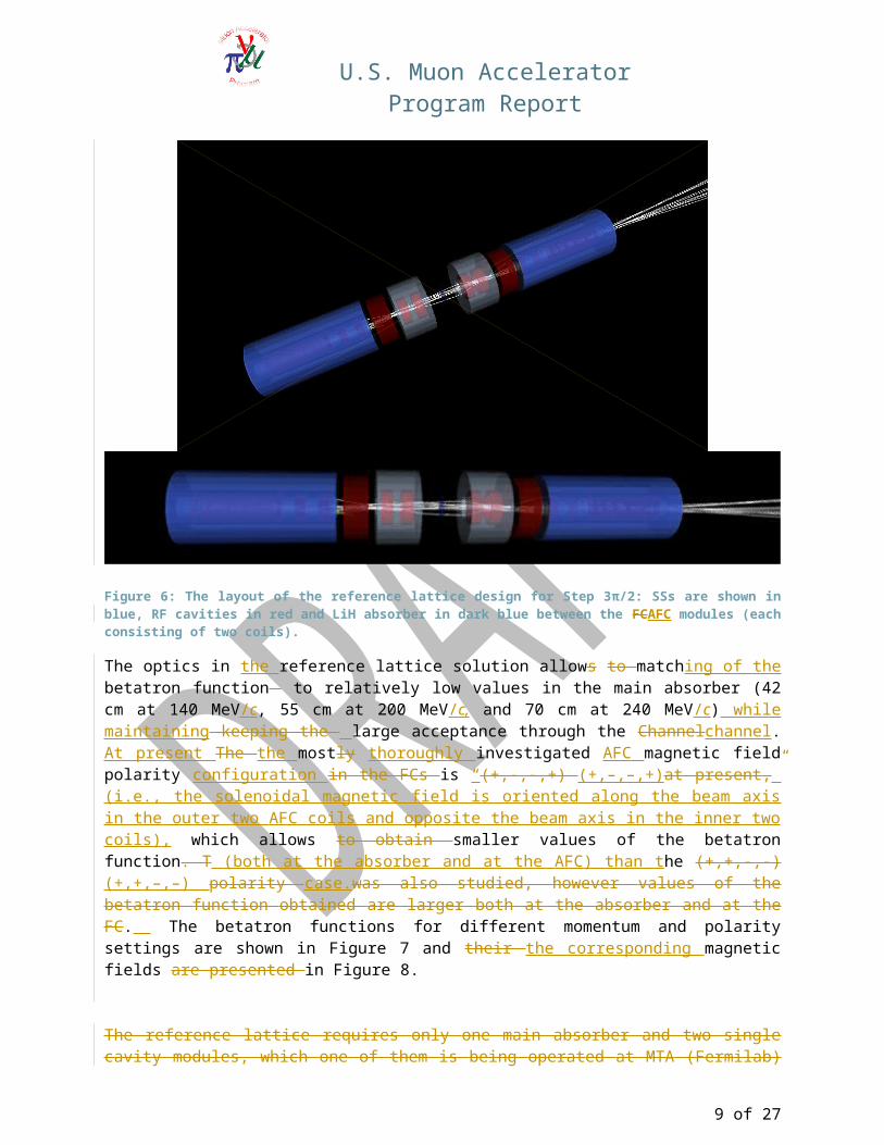
Figure 6: The layout of the reference lattice design for Step 3π/2: SSs are shown in blue, RF cavities in red and LiH absorber in dark blue between the FCAFC modules (each consisting of two coils).
6 of 21
U.S. Muon Accelerator Program Report
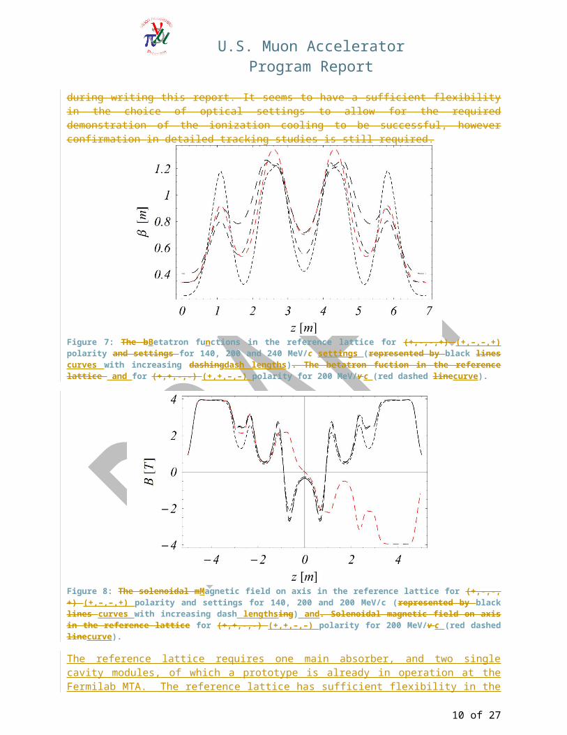
The optics in the reference lattice solution allows to matching of the betatron function to relatively low values in the main absorber (42 cm at 140 MeV/c, 55 cm at 200 MeV/c, and 70 cm at 240 MeV/c) while maintaining keeping the large acceptance through the Channelchannel. At present The the mostly thoroughly investigated AFC magnetic field polarity configuration in the FCs is “(+,-,-,+) (+,–,–,+)at present,” (i.e., the solenoidal magnetic field is oriented along the beam axis in the outer two AFC coils and opposite the beam axis in the inner two coils), which allows to obtain smaller values of the betatron function. T (both at the absorber and at the AFC) than the (+,+,-,-) (+,+,–,–) polarity case.was also studied, however values of the betatron function obtained are larger both at the absorber and at the FC. The betatron functions for different momentum and polarity settings are shown in Figure 7 and their the corresponding magnetic fields are presented in Figure 8.
The reference lattice requires only one main absorber and two single cavity modules, which one of them is being operated at MTA (Fermilab) during writing this report. It seems to have a sufficient flexibility in the choice of optical settings to allow for the required demonstration of the ionization cooling to be successful, however confirmation in detailed tracking studies is still required.
Figure 7: The bBetatron functions in the reference lattice for (+,-,-,+) (+,–,–,+) polarity and settings for 140, 200 and 240 MeV/c settings (represented by black lines curves with increasing dashingdash lengths). The betatron fuction in the reference lattice and for (+,+,-,-) (+,+,–,–) polarity for 200 MeV/v c (red dashed linecurve).
7 of 21
U.S. Muon Accelerator Program Report
Figure 8: The solenoidal mMagnetic field on axis in the reference lattice for (+,-,-,+) (+,–,–,+) polarity and settings for 140, 200 and 200 MeV/c (represented by black lines curves with increasing dash lengthsing) and. Solenoidal magnetic field on axis in the reference lattice for (+,+,-,-) (+,+,–,–) polarity for 200 MeV/v c (red dashed linecurve).
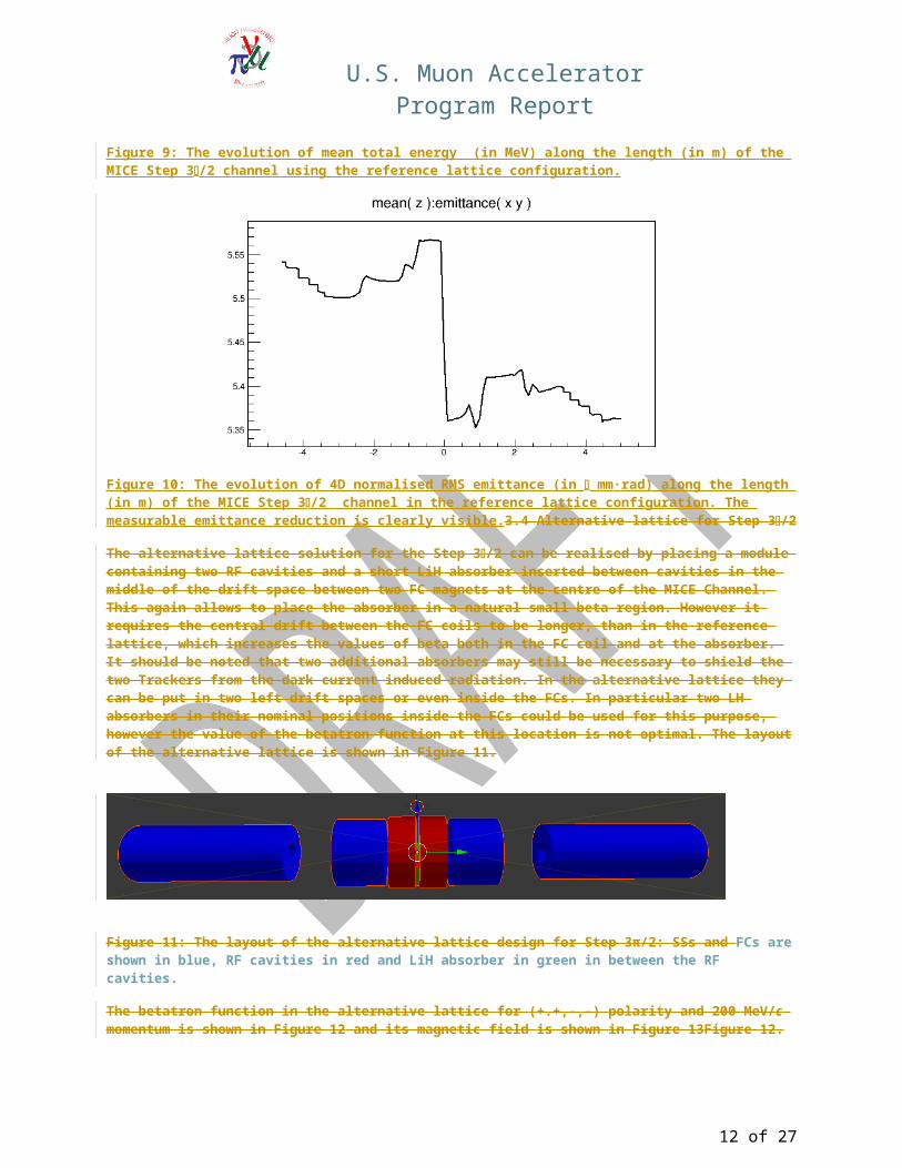
The reference lattice requires one main absorber, and two single cavity modules, of which a prototype is already in operation at the Fermilab MTA. The reference lattice has sufficient flexibility in the choice of optical settings to allow a successful demonstration of ionization cooling. Detailed tracking studies have been started, with promising results. The study was performed using the (MICE-standard) MAUS (MICE Analysis User Software) code. It performs stepwise tracking through the non-linear magnetic field of the magnets and EM fields of the RF cavities, including such details of the lattice geometry as aperture limitations and effect of materials (absorbers, Tracker planes, and RF and safety windows), using realistic models of the relevant physics processes (energy loss, straggling and multiple scattering). The evolution of muon energy as the beam traverses the MICE Step 3/2 channel based on the reference lattice is shown in Figure 9. The effect of the two accelerating cavities increasing the energy on both sides of the pronounced reduction due to the main LiH absorber can be clearly seen together with the small effects due to additional materials. The evolution of transverse emittance shown in Figure 10 indicates a clearly measurable emittance reduction. The amount of measurable cooling will be increased by adding side absorbers, which will shield the Tracker detectors against dark current induced radiation and will contribute to the overall cooling. This study was performed using the reference lattice with (+,–,–,+) polarity using an asymmetric matching to take into account the asymmetric energy profile (shown in Figure 9), with beam momentum of 200 MeV/c and input normalized 4D emittance of 6 mm·rad. Other lattice and beam configurations are also being studied with encouraging results.
An alternate lattice configuration has also been studied but appears to have less flexibility than the reference lattice. The optics studies are expected to continue, with the final choice to be reported at the next MICE Project Board review.
8 of 21
U.S. Muon Accelerator Program Report
Figure 9: The evolution of mean total energy (in MeV) along the length (in m) of the MICE Step 3/2 channel using the reference lattice configuration.
Figure 10: The evolution of 4D normalised RMS emittance (in mm·rad) along the length (in m) of the MICE Step 3/2 channel in the reference lattice configuration. The measurable emittance reduction is clearly visible.3.4 Alternative lattice for Step 3/2
The alternative lattice solution for the Step 3/2 can be realised by placing a module containing two RF cavities and a short LiH absorber inserted between cavities in the middle of the drift space between two FC magnets at the centre of the MICE Channel. This again allows to place the absorber in a natural small beta region. However it requires the central drift between the FC coils to be longer, than in the reference lattice, which increases the values of beta both in the FC coil and at the absorber. It should be noted that two additional absorbers may still be necessary to shield the two Trackers from the dark current induced radiation. In the alternative lattice they can be put in two left drift spaces or even inside the FCs. In particular two LH absorbers in their nominal positions inside the FCs could be used for this purpose, however the value of the betatron function at this location is not optimal. The layout of the alternative lattice is shown in Figure 11.
9 of 21
U.S. Muon Accelerator Program Report
Figure 11: The layout of the alternative lattice design for Step 3π/2: SSs and FCs are shown in blue, RF cavities in red and LiH absorber in green in between the RF cavities.
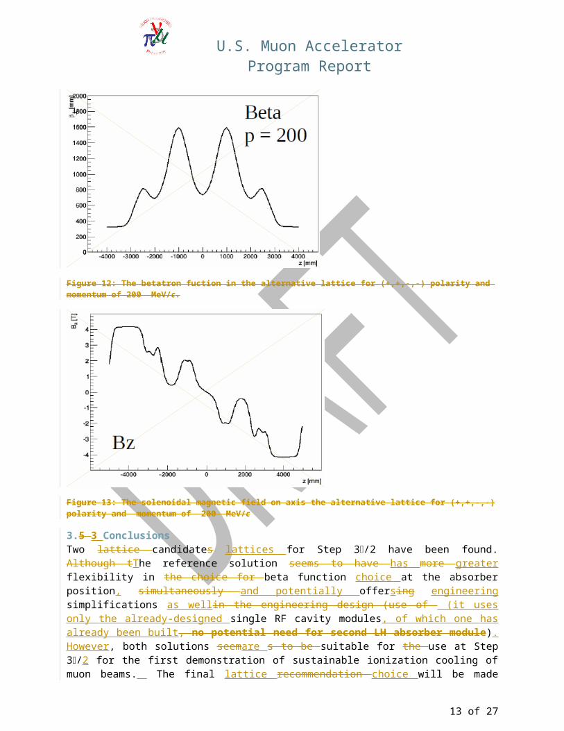
The betatron function in the alternative lattice for (+.+,-,-) polarity and 200 MeV/c momentum is shown in Figure 12 and its magnetic field is shown in Figure 13Figure 12.
Figure 12: The betatron fuction in the alternative lattice for (+,+,-,-) polarity and momentum of 200 MeV/c.
Figure 13: The solenoidal magnetic field on axis the alternative lattice for (+,+,-,-) polarity and momentum of 200 MeV/c
3.5 3 ConclusionsTwo lattice candidates lattices for Step 3/2 have been found. Although tThe reference solution seems to have has more greater flexibility in the choice for beta function choice at the absorber position, simultaneously and potentially offersing engineering simplifications as wellin the engineering design (use of (it uses only the already-designed single RF cavity modules, of which one has already been built, no potential need for second LH absorber module). However, both solutions seemare s to be suitable for the use at Step 3/2 for the first demonstration of sustainable ionization cooling of muon beams. The final lattice recommendation choice will be made based on further assessment of the performance and engineering constraints.
10 of 21

U.S. Muon Accelerator Program Report
4. The Revised MICE Project PlanOverview Section of full project to be provided by Roy Preece
The changes from the Step V arrangement of the MICE experiment to the proposed Step 3π/2 are significant. The major activities that the change has influenced reduce the timescale for the installation and so the cost accordingly. Listed below are the main activities that have been reduced or removed from the projects scope and a short description of the work that has been reduced or removed.
4.1 Summary of Modifications to UK Project PlanSection to be provided by Roy Preece and Alan Grant
4.1.1 Installation of the RFCC The RFCC assembly was a very large and complex system requiring specialist assembly and handling. Experience gained from the assembly of the Single Cavity Test chamber, at the Fermi National Laboratory, gave an incite into the amount of work required to assemble the full RFCC system at RAL. From this experience it was decided that the RFCC should be shipped with the cavities already assembled into the vacuum cavities. This method reduced the risk to the UK during the construction activity but required civil engineering work to enable the RFCC to enter the experimental hall at RAL. The work to make changes to the road way outside the experimental hall and structure of the building would have been significant timescale and cost. During any work of this kind, parallel working inside the hall would have be limited due to the area being the main entrance and exit for equipment and services.
Associated with the RFCC for cooling of the magnet were three Cryo-Cooler heads, associated compressor units, high-pressure helium lines and power. The compressors were to be installed at the west wall of the experimental hall with the services routed to the RFCC, this work is now no longer required.
The increased size of the Partial Return Yoke (US Supply) to accommodate the fringe fields from the large coupling Coil Magnet would have impinged on the mezzanine to the South of the beam line position. The changes to the mezzanine would have been significant and caused disruption to the work that could be carried out in parallel in the vicinity of the beam line. Scaffolding would be required to work on changes to the South mezzanine and a strict requirement for safe working conditions in a CDM environment would need to have been adhered to.
4.1.2 Installation of the Second Liquid Hydrogen SystemThe proposed Step 3π/2 arrangement of the MICE cooling channel utilized Lithium Hydride (LiH) as the main absorber material in favour of the originally scoped Liquid Hydrogen (LH2) Absorber system. With this change in absorber medium the second LH2 will no longer be required. The timescale and cost savings are not just in the hardware and effort associated with the construction of the Hydrogen panel, control systems and contained exhaust system, but also in the extensive safety requirements in the design, construction and operation of Hydrogen.
4.1.3 Schedule driving ActivitiesThe analysis of the proposed schedule shows that the main driver for the projects critical path is the installation and commissioning of the two RF systems required to drive the two RF cavities in the new layout. The work in-advance of the installation is being carried out at the Daresbury Laboratory, Warrington, where the build up and initial testing to 2MW, into dummy load, will be completed. The first of the amplifier systems was successfully testing in the hall at RAL to a power of 500kW into a dummy load. Following the power tests, the control racks and 4616 amplifier were removed and moved back to the Daresbury Laboratory for testing with the second TH116 amplifier.
11 of 21
U.S. Muon Accelerator Program Report
In the lead up to the completion for the construction of the Step IV arrangement of the experiment, the Daresbury Laboratory effort from the Electrical Engineering department were to concentrate on the current step. The schedule at that time for the preparation and installation of the Step V, work could be carried out sequentially, Step IV installation and then RF preparations and operations. With the expeditious nature of the schedule to complete the MICE project that is now proposed this is no longer the case and significant pressure is bearing on the electrical group to work both on the Electrical installation work at RAL and Electrical preparation work for the RF systems at Daresbury.
4.1.4 Schedule AssumptionsThe attached critical path has been constructed by changing the amount of data taking in the STEP IV arrangement to utilise all slack up to the completion of the STEP 3π/2 arrangement. The slack is created due to the delivery and subsequent installation of the RF systems, RF system 2 being the last part delivered and installed on-site at RAL. Following the RF system installation the Low and High power testing can commence and the commissioning of the whole channel can follow.
In doing this, the absolute latest date for delivery of the RF cavities and associated chambers can be found. The same is true for the PRY South and North frames and plates.
From the schedule analysis the following dates have been found:
Construction and Commissioning (taking ALL slack in the schedule)
Step IV Construction complete – 25th May 2015 Step IV Commissioning Complete – 3rd August 2015 Step IV De-Commissioning start – 2nd June 2016 Step 3π/2 Construction complete – 27th March 2017 Step 3π/2 Commissioning complete – 3rd May 2017
Data taking periods (taking ALL slack in the schedule)
Step IV Data taking - 3rd August 2015 to 2nd June 2016 Step 3π/2 data-taking period – 3rd May 2017 to 31th March 2018 (End of the UK Financial year)
Latest date for equipment delivery to RAL (taking ALL slack in the schedule)
RF Cavities and associated chambers – 1st November 2016 South PRY Frame – 15th October 2016 South PRY Plates – 26th October 2016 North PRY Frame – 1st January 2017 North PRY Plates – 10th January 2017
All tasks in the schedule have 35% time contingency added.
Interface dates defined for the delivery of the equipment required – Arrival at RAL
RF Cavities and associated chambers – 26th April 2016 South PRY Frame – 29th March 2016 South PRY Plates – 29th March 2016 North PRY Frame – 29th March 2016 North PRY Plates – 29th March 2016
12 of 21
U.S. Muon Accelerator Program Report
As already stated the schedule has removed all slack to define the latest dates for delivery of the RF cavities and chambers and the Partial Return Yoke. The period for data taking needs to be discussed by the collaboration to ascertain the correct and required length of data taking. Even with a shortened data-taking period there will still be a substantial period of data taking available.
The data-taking period for the Step 3π/2 arrangement will terminate at the end of the UK 17/18 (March 18) financial year.
4.1.5 Possible expeditersThe RF system installation is showing as the main driving activity on the critical path. The initial buildup and test at Daresbury laboratory must be carried out before the delivery to RAL and it is at this stage that the resource limiting schedule is coming into play. During this period additional staff applied to the tasks would shorten the expedited timescale for each activity. Any technical expertise that could be utilized from collaborating institutes in the Electrical and RF disciplines would expedite the schedule for completion. An estimate of two Electrical technicians and two RF expert would be required to expedite the schedule and reduce the final completion date, there is a caveat on this estimate that additional analysis of the work package schedule and discussions with senior management must be made before this estimate is confirmed.
4.1.6 ConclusionThere are many advantages for the cost and schedule coming from this proposed project plan, and also advantages for the experimental side. The proposed plan is showing the very latest dates for completing project and it can be seen that a data-taking period of 10 months would be viable for the Step IV arrangement, where significant knowledge of the operation of the magnets in a lattice and data with various absorber mediums can be gained. The knowledge of lattice operation that can be taken to the next stage will reduce commissioning and operational risk during the Step 3π/2 commissioning and operational period, which also has a significant period of data taking. The operational period shown for Step 3π/2 will terminate at the end of the UK 17/18 financial year.
13 of 21
U.S. Muon Accelerator Program Report
Table 2: Budget table (insert caption here)
Grand totals (All risk included) 2746.18 2117.82 1713.14 1460.41 8037.55Grand totals (Risk mitigation removed) 2601.18 2007.82 1713.14 1460.41 7782.55
14 of 21

U.S. Muon Accelerator Program Report
MICE-UK Cost of risk mitigation 145.00 110.00 0.00 0.00 255.00Staff element 45.00 20.00 0.00 0.00 65.00Non-staff element 100.00 90.00 0.00 0.00 190.00
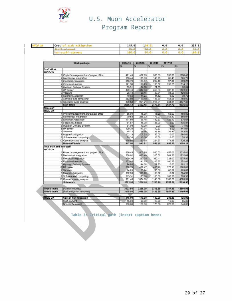
Table 3: Critical path (insert caption here)
15 of 21
U.S. Muon Accelerator Program Report
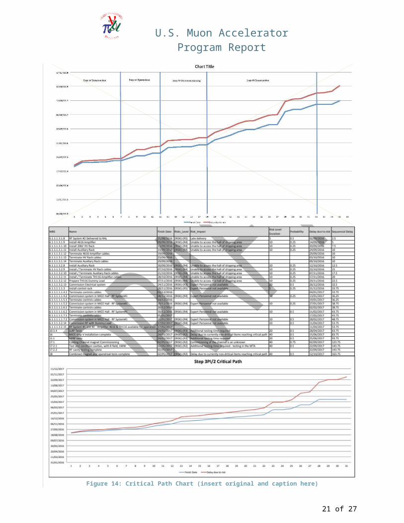
Figure 14: Critical Path Chart (insert original and caption here)
16 of 21
U.S. Muon Accelerator Program Report
Revised MIPO Milestone Table/Waterfall Plot
4.2 US Construction Project ModificationsSection provided by Alan Bross
4.2.1 MagnetsWith the adoption of the new Step X 3π/2 configuration, the US construction project has dropped the coupling coil (as well as the part of the RFCC module of which it is a part). Thus all MICE magnets that for which the US is responsible for have been delivered to Rutherford Appleton Llaboratory, having passed all acceptance criteria at the vendor prior to shipment. The only remaining US construction project magnet task with respect to magnets is commissioning of the two Spectrometer Solenoids in the MICE hall.
4.2.2 Magnetic Mitigation - Partial Return Yoke (PRY)The orders for the steel and the component fabrication for the Step IV PRY configuration are in the hands of the vendors. Fabrication of the framework parts is proceeding on schedule at Keller Technology. The 50 mm thick steel plates from JFE Steel Corporation in Japan are complete. The heat treatment for the 100 mm plate has started and they are expected to be complete by the end of September 2014. Design work on the PRY extension for Step X 3π/2 will begin as soon as the module lattice layout is complete. We plan to utilize the same vendors (for steel and fabrication) for the Step 3π/2 PRY extension.
4.2.3 RFAs shown in the Step 3π/2X lattice configuration (see Figure 6Fig. XX), the RF part of the RFCC module is being replaced by two single cavity 201 MHz RF modules. Each module will contain one cavity and one absorber disk (LiH or plastic). The single cavity test system (SCTS) currently being run operating in the MuCool Test Area (MTA) at Fermilab is a very close approximation to what will be needed for MICE Step X. S(see Figure 15) is a very close approximation to what will be needed for MICE Step 3π/2.
17 of 21

U.S. Muon Accelerator Program Report
Figure 15: SCTS in the MTA
The production prototype cavity has already reached 8 MV/m (the original MICE specification) in the absence of an external magnetic field. Once the Step 3π/2X lattice configuration has been finalized, design modification of the existing SCTS vacuum vessel will begin. The cavity bodies, tuners, windows and RF power ceramic windows exist. Four new RF power couplers and 12 tuner actuators will have to be fabricated. We have production designs for the actuators and RF power couplers (for SCTS tests), but will wait for the results from the SCTS tests with B field before launching full production. Component fabrication can begin as soon as funds are available.
4.3 US Construction Budget OverviewSection to be provided by Peter Garbincius
4.4 Key Project Evaluation Criteria Revised US Risk Analysis - Alan B. , Mark, Peter
PeterG – Monday, Sept 8, 4 PM:
We distinguish R&D Risk from Contingency. Contingency is the typical project construction contingency based on incomplete specifications or design, and uncertainty in the cost estimate or in the time that will be required to perform a given task. Typically, this US MICE estimate includes a 30% contingency in the cost estimate and 40% contingency in US$ for labor. There is also an overall time contingency added to the time required to do a related series of tasks. This appears in the US MICE Project Plan as the difference between the “Required” (with time contingency) and the “Ready” (without time contingency) dates.
R&D Risks are different in nature. They are cost and time estimates of what might be needed to mitigate the unknown problems that might be encountered in performing a new type of task for the first time. While the contingency is included in the baseline MICE Project Plan cost estimate and schedule, the R&D Risk is not. It is tabulated and added separately. As the MICE construction project has progressed and the definition of the MICE program has matured, many of the original R&D Risks considered through MICE Step VI have either been faced and overcome or “retired,”, sometimes accruing part of the
18 of 21

U.S. Muon Accelerator Program Report
Risk estimated cost, or have been removed as the MICE program has changed from Step VI to Step V to Step 3π/2. In November, 2013, the initial Risk Register consisted of 21 identified R&D Risks, with an estimate of $ 10.4 M to mitigate or respond to a realized Risk. As a first order guess, we assumed that only ½ of these Risks would be realized, so provided a Risk allowance of 50%*$ 10.4 M = $ 5.2 M. Since then, we added another Risk, and retired 10 of the Risks at an accrued cost of $ 973 K compared to a Risk estimate of $ 3.1 M, or a ratio of accrued to estimate of 31% (compared to our 50% assumption).
The decision to limit MICE to Step 3π/2, using only two single RF cavity modules, has greatly reduced the US MICE cost, complexity, and R&D Risks. There remain 7 Risks with total estimate of $ 3.84 M. The removal of the Coupling Coil Magnet (CCM) has removed the risks of cryostating, testing, and integrating and commissioning the CCM, while also greatly reducing the scope and risk of the Partial Return Yoke (PRY) magnetic shielding from that of Step V. Now PRY Step 3π/2 is only a 40% linear extension of the PRY Step IV and the design and installation plans and experience are of PRY IV are directly applicable to PRY 3π/2 with minimum risk. Moreover, the removal of the CCM means that the RF cavities will experience only the fields of the Absorber Focus Coils (AFC) magnets. The Single Cavity Test System SCTS, using the prototype 201 MHz RF cavities, couplers, actuators, etc., are is currently operating in the MuCool Test Area (MTA), and will operate using the MTA magnet , which was the prototype for the AFC. Therefore the systems test with magnetic field of the SCTS at MTA will test exactly a close approximation of the components and configuration (except without the PRY magnetic shielding of the couplers) as for the MICE production system and its operational conditions. The only difference between the SCTS and the production MICE RF Modules is in the vacuum end windows. After testing at MTA, the SCTS will be sent to Daresbury Laboratory to serve as a test load for the RF drive systems being prepared for the MICE installation.
The remaining active Risk Register for Step 3π/2 is shown below:in Table 4.
Table 4: MICE US Risk Register
The remaining R&D Risks are of three types: system integration, SCTS testing, and RF Module production and assembly. The SCTS has successfully operated up to 8 MV/m and 1 MW power. Step
19 of 21
U.S. Muon Accelerator Program Report
3π/2 requires 12 MV/m. Although testing in the magnetic field has not been done yet, testing with a similar prior RF cavity in this magnetic field has indicated that no problems should be anticipated. The successful assembly and operation of the SCTS using prototype MICE RF Module components has already been demonstrated. The system integration Risks will only be faced when the components are delivered, installed, and commissioned at RAL. The questions here will be whether the pieces fit together properly and whether there unforeseen interactions between the Spectrometer Solenoid, AFC, RF Modules, and PRY systems. These will have to be addressed by sending engineers to RAL to assess and possibly make local field modifications, so a relatively large $ Risk estimate is retained.
Revised US Milestone Table/Waterfall Plot - Rich, Peter, MarkPeterG – Monday, Sept 8, 4 PM
From 14-09-08 MICE Project PlanMajor US MICE Deliverable dates to RAL are:
March 24, 2015 – completion of partial deliveries of Partial Return Yoke (PFY) for Step IV March 1, 2016 – delivery of Partial Return Yoke (PFY) for Step 3π/2
escalated this to ready to ship all PRY 3π/2 parts to RAL by January 2016also need to re-name RF Unit & RFCC#1 => RF Module #1 and RF Module #2
August 1, 2016 – delivery of MICE RF Module #1 and Module #2
Revised UK Risk Analysis - Roy, Alan G.
Revised MIPO Milestone Table/Waterfall Plot
20 of 21
U.S. Muon Accelerator Program Report
5. ConclusionOverall impacts and plans for MAP effort (including MICE) given the $9M-$6M-$3M budget profile.
21 of 21
![R2019 49P1 [60 marks]R2019_49P1 [60 marks]1. A particle moving in a circle completes 5 revolutions in 3 s. What is the frequency? A. Hz B. Hz C. Hz D. Hz Markscheme B 3 5 5 3 3π 5](https://static.fdocument.org/doc/165x107/5ea2708926812946286ee6d1/r2019-49p1-60-marks-r201949p1-60-marks1-a-particle-moving-in-a-circle-completes.jpg)