Technical Data Sheet Gamma 12 - Sifam Tinsley UK No.GA12 /2015/02 Measuring voltage with resistance...
9
Gamma 12 It is Analog Digital Multimeter which measures VAC, VDC, VAC+DC,Frequency, mA DC, mA (AC+DC), Resistance, continuity, Diode, Farad, AC current measurement. Special Features Technical Data Sheet Gamma 12 Gamma 12 Automatic terminal blocking system (ABS) Min/Max value storage Indication of negative values on the analog scale Overload warning
Transcript of Technical Data Sheet Gamma 12 - Sifam Tinsley UK No.GA12 /2015/02 Measuring voltage with resistance...
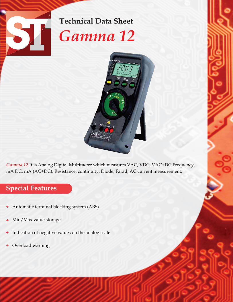
Gamma 12 It is Analog Digital Multimeter which measures VAC, VDC, VAC+DC,Frequency,
mA DC, mA (AC+DC), Resistance, continuity, Diode, Farad, AC current measurement.
Special Features
Technical Data Sheet
Gamma 12Gamma 12
Automatic terminal blocking system (ABS)
Min/Max value storage
Indication of negative values on the analog scale
Overload warning
Application
www.sifamtinsley.com Page 1 of 8
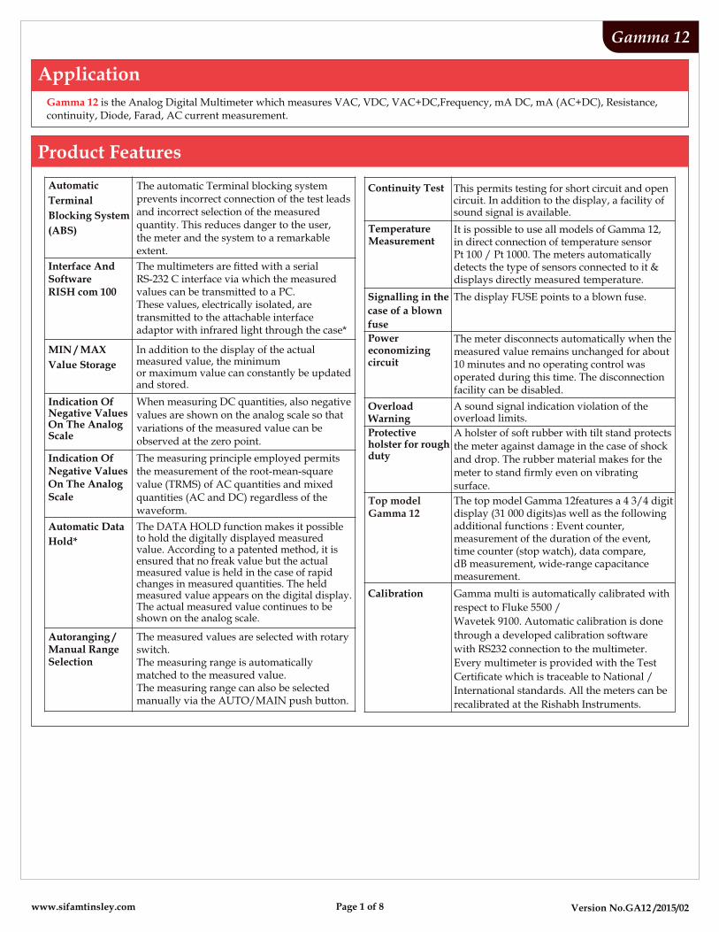
Gamma 12 is the Analog Digital Multimeter which measures VAC, VDC, VAC+DC,Frequency, mA DC, mA (AC+DC), Resistance,continuity, Diode, Farad, AC current measurement.
Product Features
Version No.GA12 /2015/02
Gamma 12
Automatic
Terminal
Blocking System
(ABS)
The automatic Terminal blocking systemprevents incorrect connection of the test leadsand incorrect selection of the measuredquantity. This reduces danger to the user,the meter and the system to a remarkableextent.
Continuity Test This permits testing for short circuit and opencircuit. In addition to the display, a facility ofsound signal is available.
Interface AndSoftwareRISH com 100
MIN / MAX
Value Storage
In addition to the display of the actualmeasured value, the minimum or maximum value can constantly be updatedand stored.
Indication OfNegative ValuesOn The AnalogScale
When measuring DC quantities, also negativevalues are shown on the analog scale so thatvariations of the measured value can be observed at the zero point.
Indication OfNegative ValuesOn The AnalogScale
The measuring principle employed permitsthe measurement of the root-mean-squarevalue (TRMS) of AC quantities and mixedquantities (AC and DC) regardless of thewaveform.
Automatic Data
Hold*
The DATA HOLD function makes it possibleto hold the digitally displayed measuredvalue. According to a patented method, it is ensured that no freak value but the actualmeasured value is held in the case of rapidchanges in measured quantities. The held measured value appears on the digital display.The actual measured value continues to beshown on the analog scale.
Autoranging /Manual RangeSelection
The measured values are selected with rotaryswitch.The measuring range is automatically matched to the measured value.The measuring range can also be selectedmanually via the AUTO/MAIN push button.
TemperatureMeasurement
It is possible to use all models of Gamma 12,in direct connection of temperature sensorPt 100 / Pt 1000. The meters automaticallydetects the type of sensors connected to it &displays directly measured temperature.
Signalling in the
case of a blown
fuse
The display FUSE points to a blown fuse.
Powereconomizingcircuit
The meter disconnects automatically when themeasured value remains unchanged for about10 minutes and no operating control wasoperated during this time. The disconnectionfacility can be disabled.
OverloadWarning
A sound signal indication violation of theoverload limits.
Protectiveholster for roughduty
The top model Gamma 12features a 4 3/4 digitdisplay (31 000 digits)as well as the followingadditional functions : Event counter,measurement of the duration of the event,time counter (stop watch), data compare,dB measurement, wide-range capacitancemeasurement.
Calibration
Top modelGamma 12
Version No.GA12 /2015/02
0
Gamma 12
Environmental conditionsTemperature range 0-10 C... + 50 C
Storage temperaturerange
0 0-25 C ... +70 C (excl. batteries)
Climatic class 2z/-10/50/70/75%with reference to VDI/VDE 3540
Altitude above sea level up to 2000m
Warranty3 year against defects in materials and workmanship &calibration from the date of purchase.
Scope of delivery
Applied rules and standardsSafety requirements for electricalequipment for measurement,control and laboratory use.
IEC 61010-1:2001DIN EN 61010 part 1VDE 0411 -1
Digital measuring instruments
Generic immunity standard;residential, commercial and lightindustry
Reliability of measuring andcontrol equipment.
Test equipment and test procedures-Degrees of protection provided byenclosures (IP Code)
DIN EN 60529
DIN VDE 0470 part 1
VDI/VDE 3540
EN 61326:2002
DIN 43751 IS 13875
EN 61326:2002 Generic emission standard;Residential, commercial and lightindustry
Protection type For meters; IP 50,for connection sockets: IP 20
Dimensions 84 mm x 195 mm x 35 mm
Weight 0.35 kg, approx., incl. battery
Scale length
Scaling
Polarity indication
Overrange indication
Sampling rate
55 mm on V and A ;47 mm on all other ranges
0…30 with 30 scale divisionson all other ranges
With automatic reversal
By triangle
20 readings/s,On 10 readings/s
--- ---
+ 5…0…+ 30 with 35 scaledivisions on ,---
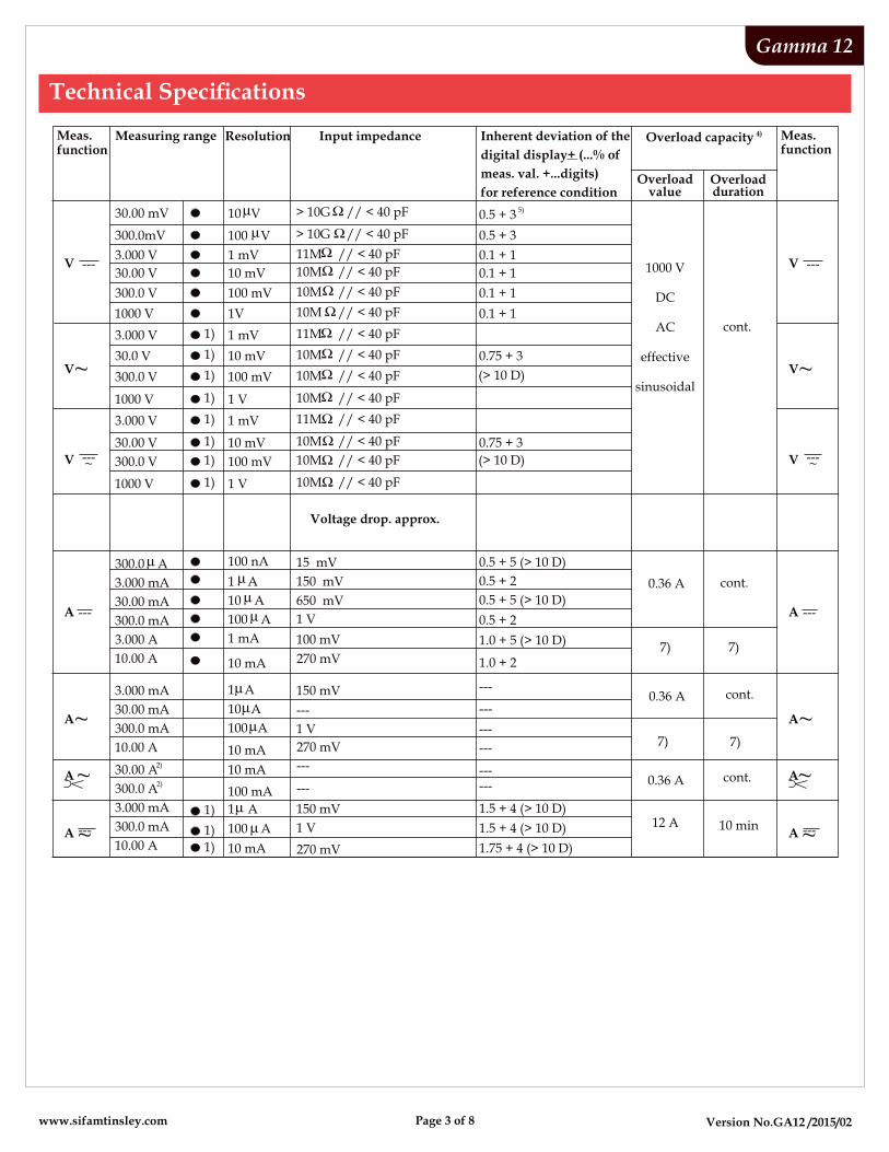
AnalogIndication LCD scale with pointer
Digital
Display/ height ofnumerals
7 segment numerals / 15mm
Number of counts Gamma 12,3 ¾ digit 3100 countsGamma 10:4 ¾ digit 31000 counts
Overange display "OL" is shown
Polarity display "-" sign is shown,When positive pole to “ “
Sampling rate 2 readings/s,0On and C:1 reading/s
MAN DATA MIN MAX
11
1
12
2
°C
9 8
7
10
3 4 5 6
..5 0 10 20 30
DC AC
kHz%
mVA
k M
nF µF
ON
+ +
Display
www.sifamtinsley.com Page 2 of 8
0
Version No.GA12 /2015/02
Gamma 12
10M // < 40 pF
10M // < 40 pF
11M // < 40 pF
> 10G // < 40 pF
> 10G // < 40 pF
---~A
0.5 + 5 (> 10 D)
0.5 + 2
1 mV
10 mV
100 mV
1 V
1)
1)
1)
1)
1)
1)
1)
1)
1 mV
10 mV
100 mV
1 V
Voltage drop. approx.
1)
1)
1)
100 nA
1 mA
10 mA
15 mV
150 mV
150 mV
150 mV
650 mV
1 V
100 mV
270 mV
270 mV
270 mV
---
---
---
1 V
1 V
0.5 + 5 (> 10 D)
0.5 + 2
1.0 + 5 (> 10 D)
1.0 + 2
---
---
---
---
------
1.5 + 4 (> 10 D)
1.5 + 4 (> 10 D)
1.75 + 4 (> 10 D)
0.36 A
0.36 A
0.36 A
10 mA
10 mA
100 mA
10 mA
1V 0.1 + 1
0.75 + 3
(> 10 D)
0.75 + 3
(> 10 D)
10M // < 40 pF
11M // < 40 pF
10M // < 40 pF
10M // < 40 pF
10M // < 40 pF
11M // < 40 pF
10M // < 40 pF
10M // < 40 pF
10M // < 40 pF
1 A
10 A
1 A
10 A
100 A
1 A
100 A
100 A
12 A
1000 V
DC
AC
effective
sinusoidal
cont.
cont.
cont.
cont.
7) 7)
7)
10 min
7)
1000 V
3.000 V
30.0 V
300.0 V
1000 V
3.000 V
30.00 V
300.0 V
1000 V
3.000 mA
30.00 mA
300.0 mA
3.000 A
10.00 A
3.000 mA
30.00 mA
300.0 mA
10.00 A
300.0 A
2)30.00 A
2)300.0 A
3.000 mA
300.0 mA
10.00 A
Meas.function
30.00 mV
300.0mV
3.000 V
30.00 V
300.0 V
1 mV
10 mV
100 mV
5)0.5 + 3
0.5 + 3
0.1 + 1
0.1 + 1
0.1 + 1
Overloadvalue
Overloadduration
A ~
10 V
100 V
A~
A ---
V ---~
V ---
V ~
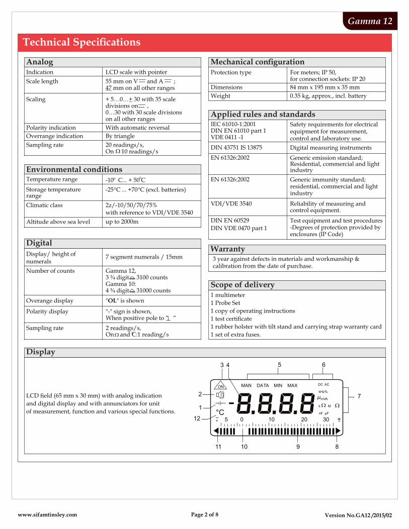
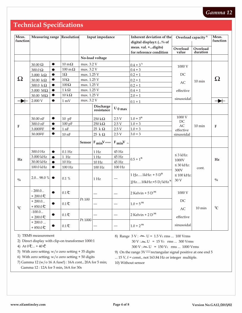
Measuring range Resolution Input impedance 4)Overload capacity Meas.function
Inherent deviation of the
digital display+ (...% of
meas. val. +...digits)
for reference condition
---~A
A~
A~
A ---
V ---~
V ---
V ~
www.sifamtinsley.com Page 3 of 8
Version No.GA12 /2015/02
Gamma 12
1) TRMS measurement
2) Direct display with clip-on transformer 1000:10 04) At 0 C... + 40 C
5) With zero setting; w/o zero setting + 35 digits
6) With zero setting; w/o zero setting + 50 digits
7) Gamma 12 (w/o 16 A fuse!) : 16A cont., 20A for 5 min;
Gamma 12 : 12A for 5 min, 16A for 30s
No-load voltage
10 pF
100 pF
1 nF
10 nF
0.1 Hz
1 Hz
10 Hz
100 Hz
1 Hz
1 Hz
10 Hz
100 Hz
45 Hz
45 Hz
45 Hz
100 Hz
2.5 V
2.5 V
2.5 V
2.5 V
6)1.0 + 3
1.0 + 3
1.0 + 3
3.0 + 3
Dischargeresistance
U 0 max
max. 3.2 V
max. 3.2 V
max. 1.25 V
max. 1.25 V
max. 1.25 V
max. 1.25 V
max. 1.25 V
max. 3.2 V
5)0.4 + 3
0.4 + 3
0.2 + 1
0.2 + 1
0.2 + 1
0.4 + 1
2.0 + 1
0.1 + 11 mV
250 k
250 k
25 k
25 k
10 m
100 m
1
10
100
1 k
10 k
8)1 Hz.....1kHz: + 5 D
8)0.5 + 1
Sensor
F V min ~
F V min
1000 V
DC
AC
effective
sinusoidal
1000 VDCAC
effective sinusoidal
≤ 3 kHz:
1000V
≤ 30 kHz:
300V
≤ 100 kHz:
30 V
10 min
cont.
10 min
2.000 V
30.00 nF
300.0 nF
30.00
300.0
3.000 k
30.00 k
300.0 k
3.000 M
30.00 M
300.0 Hz
3.000 kHz
30.00 kHz
100.0 kHz
3.000 F
30.00 F
F
Hz
F
Hz
00.1 C
0.1 % 1 Hz
Pt 100
Pt 1000
---
---
---
---
---
---
---
---
---9)
1Hz.....10kHz:+5 D/kHz
10)2 Kelvin + 5 D
10)1.0 + 5
10)2 Kelvin + 2 D
10)1.0 + 2
00.1 C
00.1 C
00.1 C 1000 V
DC
AC
effective
sinusoidal
10 min
- 200.0...0+ 200.0 C
+ 200.0...0+ 850.0 C
-100.0...0+ 200.0 C
+ 200.0 ...0+ 850.0 C
2.0... 98.0 %%
0C
%
0C
Meas.function
Overloadvalue
Overloadduration
Measuring range Resolution Input impedance 4)Overload capacity Meas.function
Inherent deviation of the
digital display+ (...% of
meas. val. +...digits)
for reference condition
8) Range 3 V : U = 1.5 VE rms ... 100 Vrms
30 V : U = 15 VE rms ... 300 Vrms
300 V : U = 150 VE rms ... 1000 Vrms
9) On the range 3V rectangular signal positive at one end 5
... 15 V, f = const., not 163.84 Hz or integer multiple.
10) Without sensor
---
~~~
www.sifamtinsley.com Page 4 of 8
Version No.GA12 /2015/02
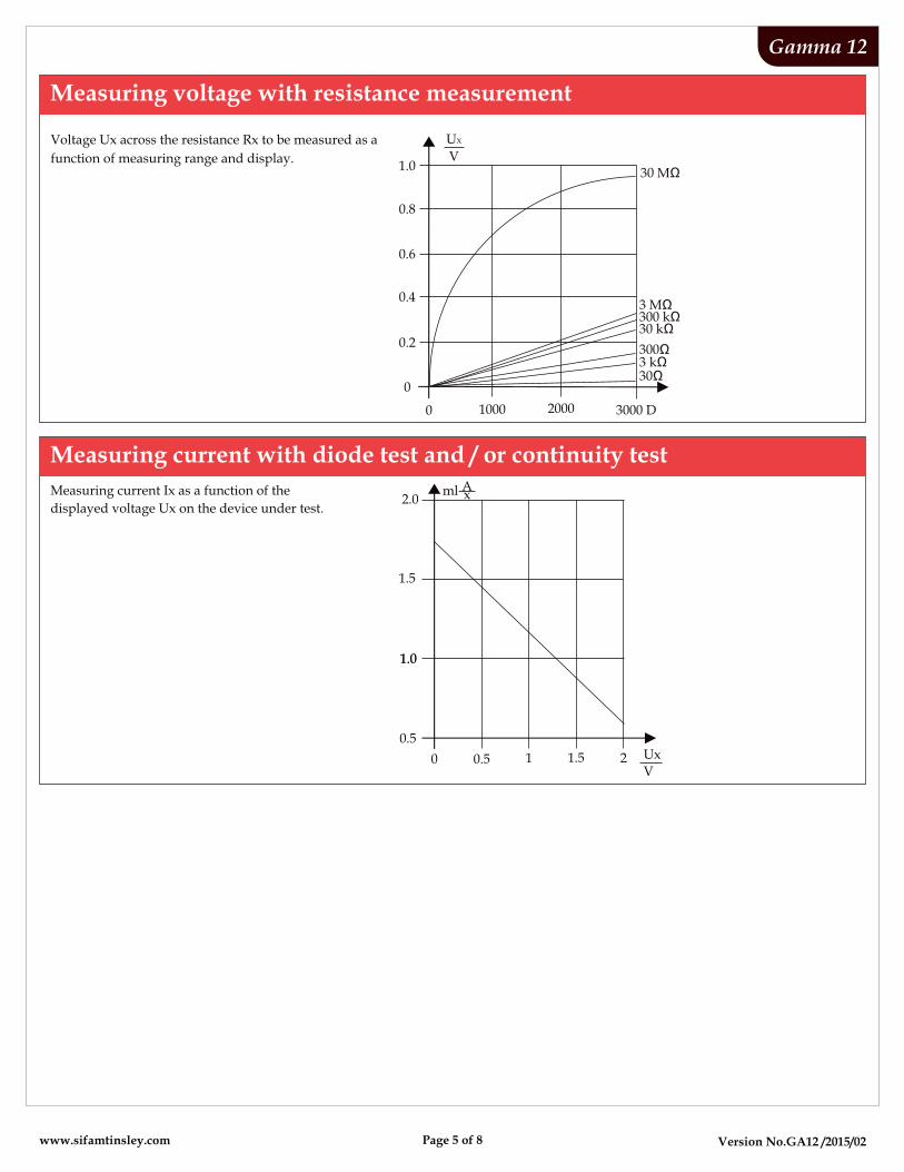
Measuring voltage with resistance measurement
Gamma 12
0
0
0.2
0.4
0.6
0.8
1.0
1000 2000 3000 D
30 MΩ
UX
V
3 MΩ300 kΩ30 kΩ
300Ω3 kΩ30Ω
Voltage Ux across the resistance Rx to be measured as a
function of measuring range and display.
Measuring current with diode test and / or continuity test
0 0.5 1 1.5 2 Ux
V
1.5
2.0
1.0
0.5
1.0
xAmlMeasuring current Ix as a function of the
displayed voltage Ux on the device under test.
www.sifamtinsley.com Page 5 of 8
Version No.GA12 /2015/02
Gamma 12
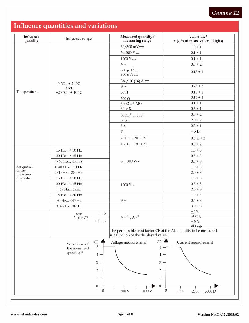
Temperature
Frequencyof themeasuredquantity
0 °C... + 21 °Cand
+25 °C... + 40 °C
15 Hz... < 30 Hz
30 Hz... < 45 Hz
> 65 Hz... 400Hz
> 400 Hz... 1 kHz
> 1kHz... 20 kHz
15 Hz... < 30 Hz
30 Hz... < 45 Hz
> 65 Hz... 1kHz
15 Hz... < 30 Hz
30 Hz... <45 Hz
> 65 Hz...1kHz
Crestfactor CF
1 ...3
> 3 ...5
4) 4)V ~ , A~
3 ... 300 V ~
1000 V ~
A~
A ~
30 Ω
300 Ω
3 k Ω... 3 MΩ
30 MΩ
2) 30 nF ... 3µF
30 µF
Hz
%
-200... + 20 0 °C
+ 200... + 8 50 °C
The permissible crest factor CF of the AC quantity to be measured is a function of the displayed value :
Waveform ofthe measured
3) quantity
Current measurementVoltage measurementCF
5
500 V 1000 V
4
3
2
1
00
CF
5
1000 2000 3000 D
4
3
2
1
00
Measured quantity /measuring range
0.75 + 3
0.5 + 2
2.0 + 2
0.5 + 1
1.0 + 3
0.5 + 3
0.5 + 3
1.0 + 3
2.0 + 3
1.0 + 3
0.5 + 3
2.0 + 3
1.0 + 3
0.5 + 3
3.0 + 3
0.15 + 2
0.1 + 1
0.6 + 1
0.5 K + 2
0.5 + 2
0.15 + 2
+ 1%of rdg.
of rdg.
+ 5 D
+ 3 %
1.0 + 1
0.1 + 1
0.1 + 1
0.3 + 2
0.15 + 1
V ~ 2
300 µ A ...
3A / 10 (16) A ---
300 mA ---
1000 V ---
3... 300 V ---
30/300 mV---
1)Variation
+ (...% of meas. val. +... digits)
www.sifamtinsley.com Page 6 of 8
Version No.GA12 /2015/02
Gamma 12
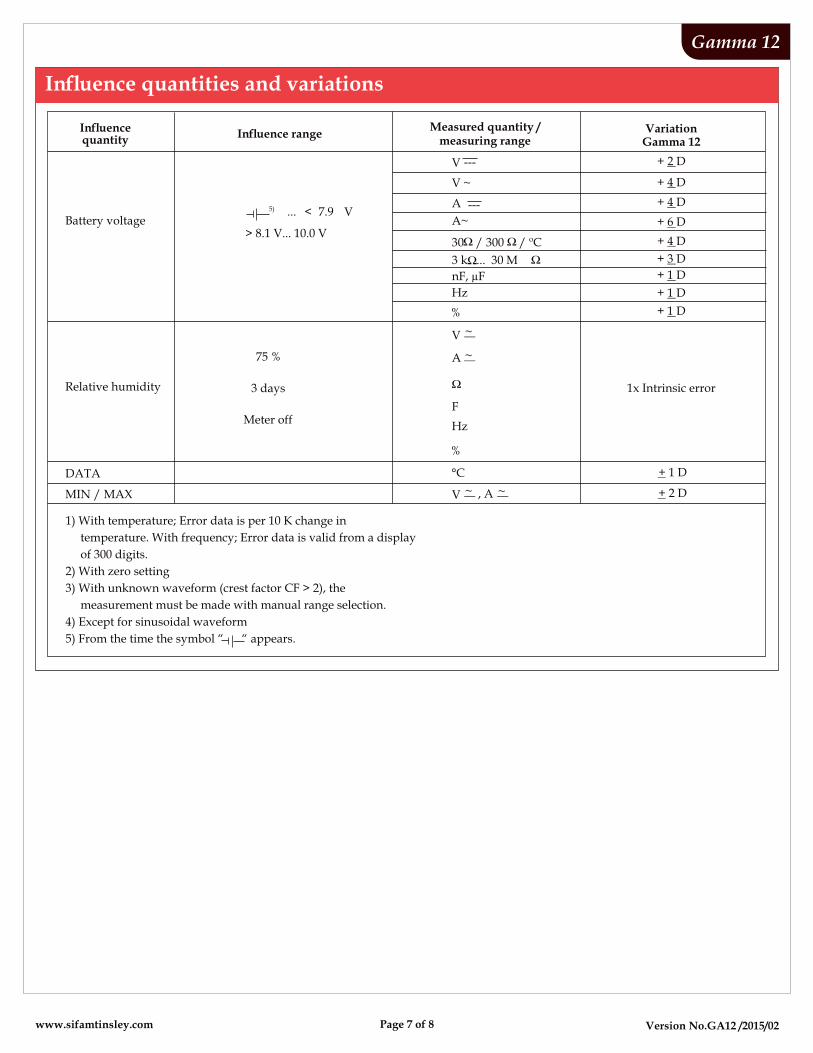
MIN / MAX
Battery voltage
Relative humidity
DATA
1x Intrinsic error
+ 4 D
+ 6 D
+ 4 D
+ 1 D
+ 1 D
+ 1 D
+ 3 D
+ 2 D
+ 4 D
Measured quantity /measuring range
VariationGamma 12
+ 2 D
+ 1 D
75 %
3 days
Meter off
... < 7.9 V5)
> 8.1 V... 10.0 V
, A ~V ~
A~
A ~
V ~
F
Hz
%
°C
A ---
nF, µF
30 / 300 / ºC
3 k ... 30 M
Hz
%
V ~
V ---
1) With temperature; Error data is per 10 K change in
temperature. With frequency; Error data is valid from a display
of 300 digits.
2) With zero setting
3) With unknown waveform (crest factor CF > 2), the
measurement must be made with manual range selection.
4) Except for sinusoidal waveform
5) From the time the symbol “ “ appears.
www.sifamtinsley.com Page 7 of 8
Version No.GA12 /2015/02
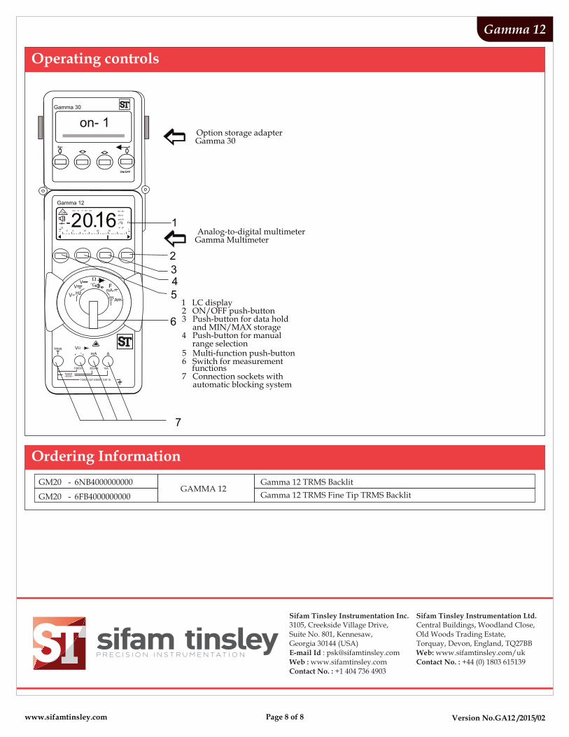
Operating controls
Gamma 12
Option storage adapterGamma 30
Analog-to-digital multimeterGamma Multimeter
1 LC display2 ON/OFF push-button3 Push-button for data hold and MIN/MAX storage4 Push-button for manual range selection5 Multi-function push-button6 Switch for measurement functions7 Connection sockets with automatic blocking system
Esc
ON/OFF
on- 1
MAN DA TA MIN MAX
°C 5 0 10 20 30
DC AC
kHz%
µmVA
k M
nF µF
ON
++
20.16
mA AT
2
V
fused
10A1000V
V---
mA---°C
345
6
7
1
Gamma 12
Gamma 30
300mA
O
F C
V~
~ F
---~
Hz
A---
TRMS
www.sifamtinsley.com Page 8 of 8
Sifam Tinsley Instrumentation Inc.3105, Creekside Village Drive,Suite No. 801, Kennesaw,Georgia 30144 (USA)E-mail Id : [email protected] : www.sifamtinsley.comContact No. : +1 404 736 4903
Sifam Tinsley Instrumentation Ltd.Central Buildings, Woodland Close,Old Woods Trading Estate, Torquay, Devon, England, TQ27BBWeb: www.sifamtinsley.com/ukContact No. : +44 (0) 1803 615139
Ordering Information
GM20 - 6NB4000000000GAMMA 12
Gamma 12 TRMS Backlit
GM20 - 6FB4000000000 Gamma 12 TRMS Fine Tip TRMS Backlit