Status of the Telescope Array - UNISTsirius.unist.ac.kr/kaw4/presnt-5-19/1-sagawa.pdf · April 19,...
41
April 19, 2006 1 Status of the Telescope Array H. Sagawa (ICRR) on Behalf of TA Collaboration @ KASI Daejeon, Korea 19 May, 2006
-
Upload
truongcong -
Category
Documents
-
view
220 -
download
3
Transcript of Status of the Telescope Array - UNISTsirius.unist.ac.kr/kaw4/presnt-5-19/1-sagawa.pdf · April 19,...
April 19, 2006 1
Status of the Telescope Array
H. Sagawa (ICRR)on Behalf of TA Collaboration
@ KASI Daejeon, Korea19 May, 2006
2
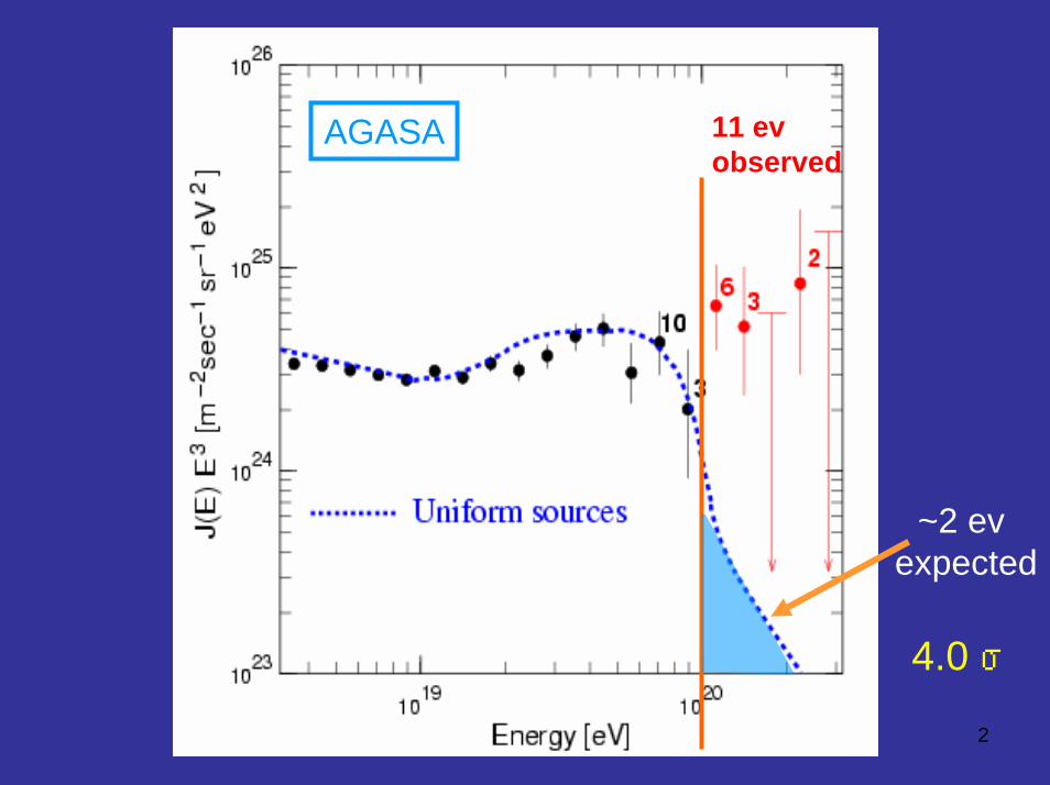
AGASA
~2 evexpected
11 evobserved
4.0 σ
3
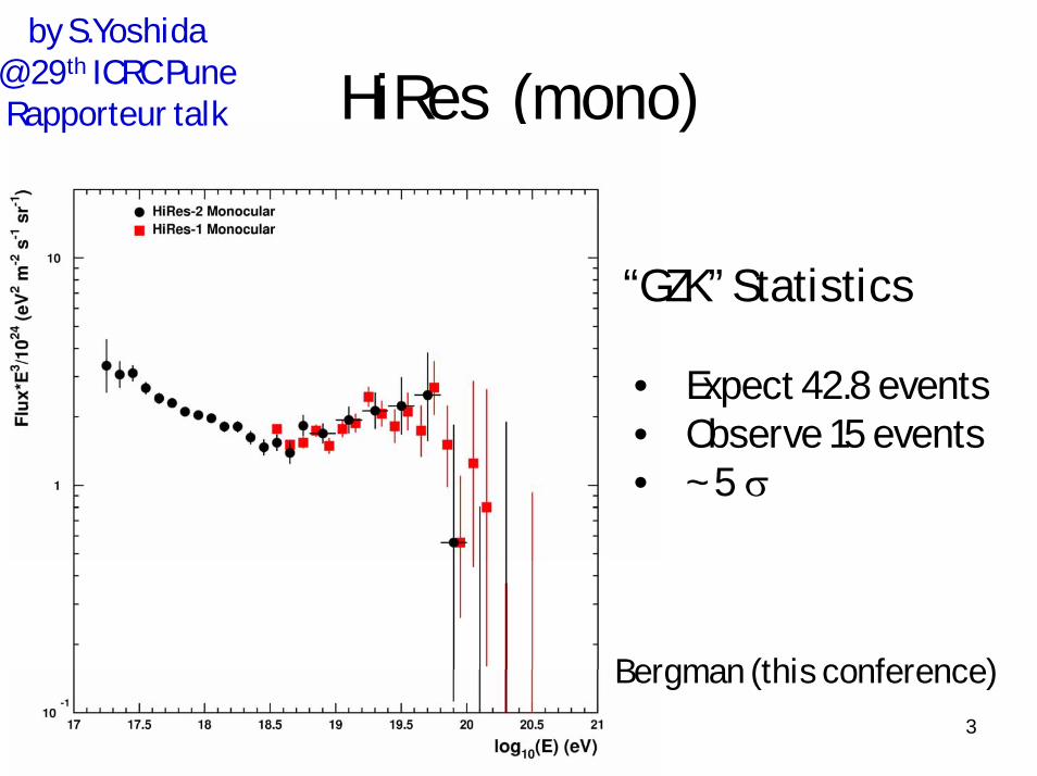
HiRes (mono)
• Expect 42.8 events• Observe 15 events• ~ 5 σ
“GZK” Statistics
Bergman (this conference)
by S.Yoshida@ 29th ICRC PuneRapporteur talk
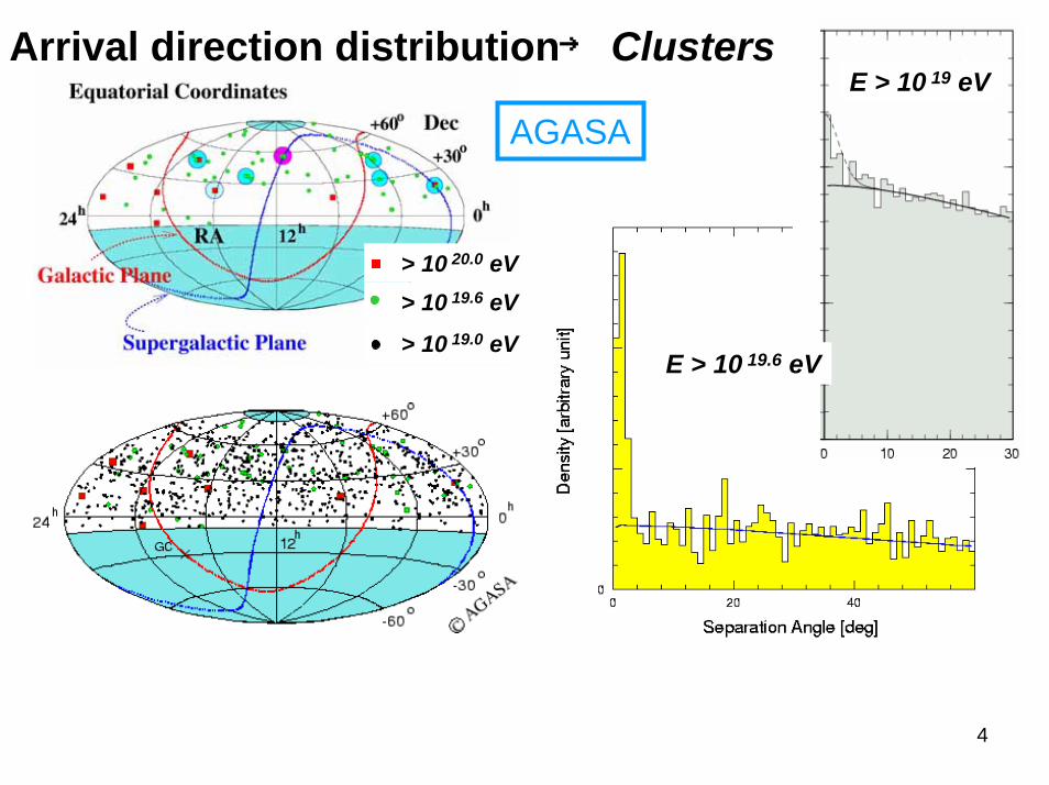
AGASAE > 10 19 eV
E > 10 19.6 eV
> 10 20.0 eV> 10 19.6 eV
> 10 19.0 eV
Arrival direction distribution→ Clusters
4
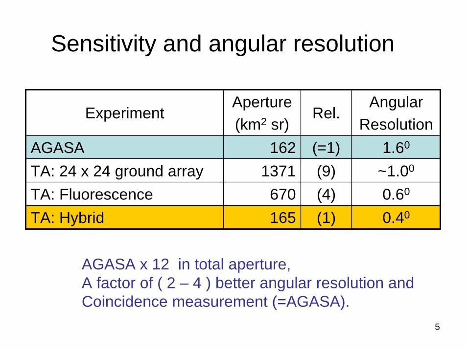
Sensitivity and angular resolution
ExperimentAperture(km2 sr)
Rel.Angular
ResolutionAGASA 162 (=1) 1.60
(9) ~1.00
0.60
0.40
(4)(1)
TA: 24 x 24 ground array 1371TA: Fluorescence 670TA: Hybrid 165
AGASA x 12 in total aperture,A factor of ( 2 – 4 ) better angular resolution andCoincidence measurement (=AGASA).
5
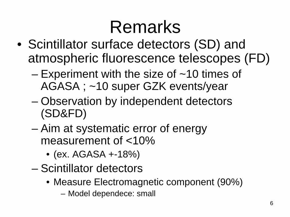
Remarks• Scintillator surface detectors (SD) and
atmospheric fluorescence telescopes (FD)– Experiment with the size of ~10 times of
AGASA ; ~10 super GZK events/year– Observation by independent detectors
(SD&FD)– Aim at systematic error of energy
measurement of <10%• (ex. AGASA +-18%)
– Scintillator detectors• Measure Electromagnetic component (90%)
– Model dependece: small6
• Originally TA was funded by JSPS (Japan Society for the Promotion of Science)
• Funding started in JFY2003• Construction period (JFY2003~JFY2006)• Regular observation should start in
JFY2007 ( 2007 April ~ )
7
8
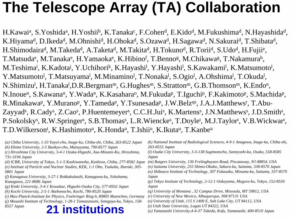
The Telescope Array (TA) Collaboration H.Kawaia, S.Yoshidaa, H.Yoshiib, K.Tanakac, F.Cohend, E.Kidod, M.Fukushimad, N.Hayashidad, K.Hiyamad, D.Ikedad, M.Ohnishid, H.Ohokad, S.Ozawad, H.Sagawad, N.Sakuraid, T.Shibatad, H.Shimodairad, M.Takedad, A.Taketad, M.Takitad, H.Tokunod, R.Toriid, S.Udod, H.Fujiie, T.Matsudae, M.Tanakae, H.Yamaokae, K.Hibinof, T.Bennog, M.Chikawag, T.Nakamurah, M.Teshimai, K.Kadotaj, Y.Uchihorik, K.Hayashil, Y.Hayashil, S.Kawakamil, K.Matsumotol, Y.Matsumotol, T.Matsuyamal, M.Minaminol, T.Nonakal, S.Ogiol, A.Ohshimal, T.Okudal, N.Shimizul, H.Tanakal,D.R.Bergmanm, G.Hughesm, S.Strattonm, G.B.Thomsonm, K.Endon, N.Inouen, S.Kawanan, Y.Wadan, K.Kasaharao, M.Fukudap, T.Iguchip, F.Kakimotop, S.Machidap, R.Minakawap, Y.Muranop, Y.Tamedap, Y.Tsunesadap, J.W.Belzqs, J.A.J.Matthewsr, T.Abu-Zayyads, R.Cadys, Z.Caos, P.Huentemeyers, C.C.H.Juis, K.Martenss, J.N.Matthewss, J.D.Smiths, P.Sokolskys, R.W.Springers, S.B.Thomass, L.R.Wienckes, T.Doylet, M.J.Taylort, V.B.Wickwart, T.D.Wilkersont, K.Hashimotou, K.Hondau, T.Ishiiu, K.Ikutau, T.Kanbeu
(a) Chiba University, 1-33 Yayoi-cho, Inage-ku, Chiba-shi, Chiba, 263-8522 Japan(b) Ehime University, 2-5 Bunkyo-cho, Matsuyama, 790-8577 Japan(c) Hiroshima City University, 3-4-1 Ozuka-Higashi, Asa-Minami-Ku, Hiroshima, 731-3194 Japan(d) ICRR, University of Tokyo, 5-1-5 Kashiwanoha, Kashiwa, Chiba, 277-8582 Japan(e) Institute of Particle and Nuclear Studies, KEK, 1-1 Oho, Tsukuba, Ibaraki, 305-0801 Japan(f) Kanagawa University, 3-27-1 Rokkakubashi, Kanagawa-ku, Yokohama, Kanagawa, 221-8686 Japan(g) Kinki University, 3-4-1 Kowakae, Higashi-Osaka City, 577-8502 Japan(h) Kochi University, 2-5-1 Akebonocho, Kochi, 780-8520 Japan(i) Max-Planck-Institute for Physics, Foehringer Ring 6, 80805 Muenchen, Germany (j) Musashi Institute of Technology, 1-28-1 Tamazutsumi, Setagaya-ku, Tokyo, 158-8557 Japan
(k) National Institute of Radiological Sciences, 4-9-1 Anagawa, Inage-ku, Chiba-shi, 263-8555 Japan(l) Osaka City University, 3-3-138 Sugimotocho, Sumiyoshi-ku, Osaka, 558-8585 Japan(m) Rutgers University, 136 Frelinghuysen Road, Piscataway, NJ 08854, USA(n) Saitama University, 255 Shimo-Okubo, Sakura-ku, Saitama, 338-8570 Japan(o) Shibaura Institute of Technology, 307 Fukasaku, Minuma-ku, Saitama, 337-8570 Japan(p) Tokyo Institute of Technology, 2-12-1 Ookayama, Meguro-ku, Tokyo, 152-8550 Japan(q) University of Montana , 32 Campus Drive, Missoula, MT 59812, USA(r) University of New Mexico, Albuquerque, NM 87131 USA(s) University of Utah, 115 S 1400 E, Salt Lake City, UT 84112, USA(t) Utah State University, Logan UT 84322, USA(u) Yamanashi University,4-4-37 Takeda, Kofu, Yamanashi, 400-8510 Japan21 institutions
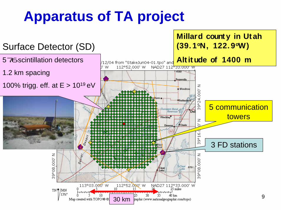
Apparatus of TA project
930 km
576 scintillation detectors
1.2 km spacing
100% trigg. eff. at E > 1019 eV
Millard county in Utah (39.1oN, 122.9oW)
Altitude of 1400 m Surface Detector (SD)
3 FD stations
5 communication towers
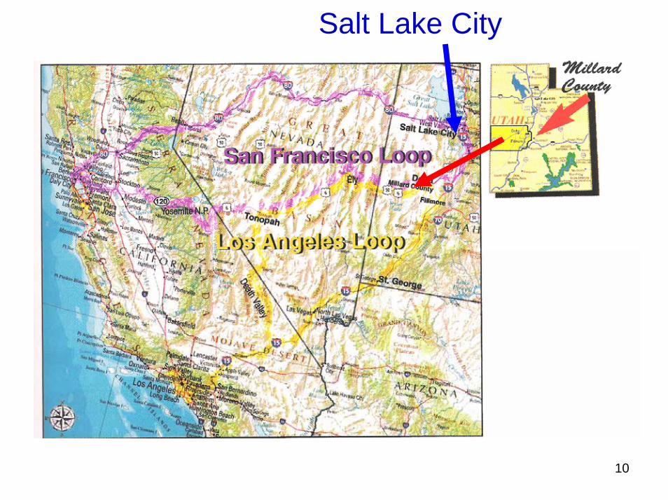
Salt Lake City
10
Surface Detector (SD)
11
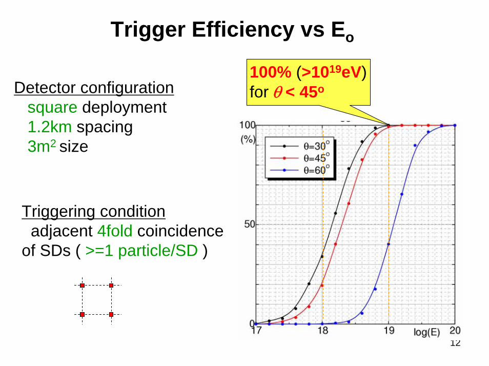
Trigger Efficiency vs Eo
12
100% (>1019eV)for θ < 45oDetector configuration
square deployment1.2km spacing3m2 size
Triggering conditionadjacent 4fold coincidence
of SDs ( >=1 particle/SD )
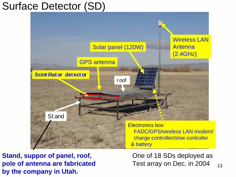
Scintillator detector
GPS antenna
Solar panel (120W)Wireless LANAntenna(2.4GHz)
Stand
roof
Surface Detector (SD)
Electronics boxFADC/GPS/wireless LAN modem/charge controller/slow controller
& battery
Stand, suppor of panel, roof, pole of antenna are fabricated by the company in Utah.
One of 18 SDs deployed as Test array on Dec. in 2004 13

Scintillation Detector
14
Scintillator3m2 area 1.2cmt 2 layers
WLSF1.0mm φ 2 cm interval
Output2 PMTs(upper PMT + lower PMT)
Scintillator box
230 x 170 x 10(cm3)
Total weight ~200 kg
separated optically
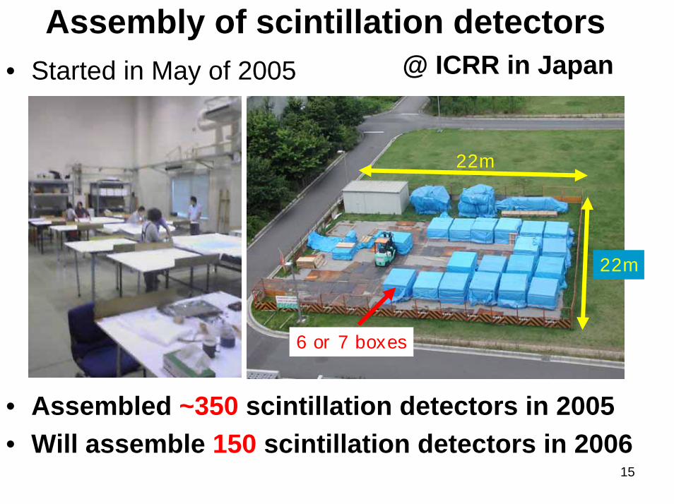
Assembly of scintillation detectors@ ICRR in Japan• Started in May of 2005
22m
22m
6 or 7 boxes
• Assembled ~350 scintillation detectors in 2005• Will assemble 150 scintillation detectors in 2006
15
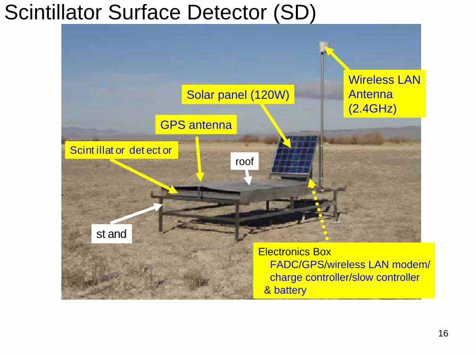
Scintillator detector
GPS antenna
Solar panel (120W)Wireless LANAntenna(2.4GHz)
stand
roof
Scintillator Surface Detector (SD)
Electronics BoxFADC/GPS/wireless LAN modem/charge controller/slow controller
& battery
16
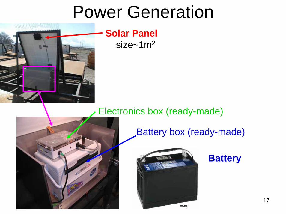
Power Generation
Battery
Battery box (ready-made)
Electronics box (ready-made)
Solar Panelsize~1m2
17
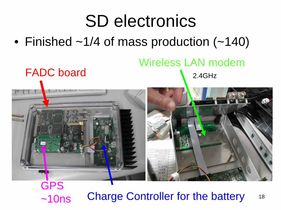
SD electronics• Finished ~1/4 of mass production (~140)
Wireless LAN modemFADC board
GPS~10ns Charge Controller for the battery
2.4GHz
18

Scintillator detector
GPS antenna
Solar panel (120W)
Wireless LANAntenna(2.4GHz)
stand
roof
Surface Scintillator Detector (SD)
Electronics BoxFADC/GPS/wireless LAN modem/charge controller/slow controller
& battery
19
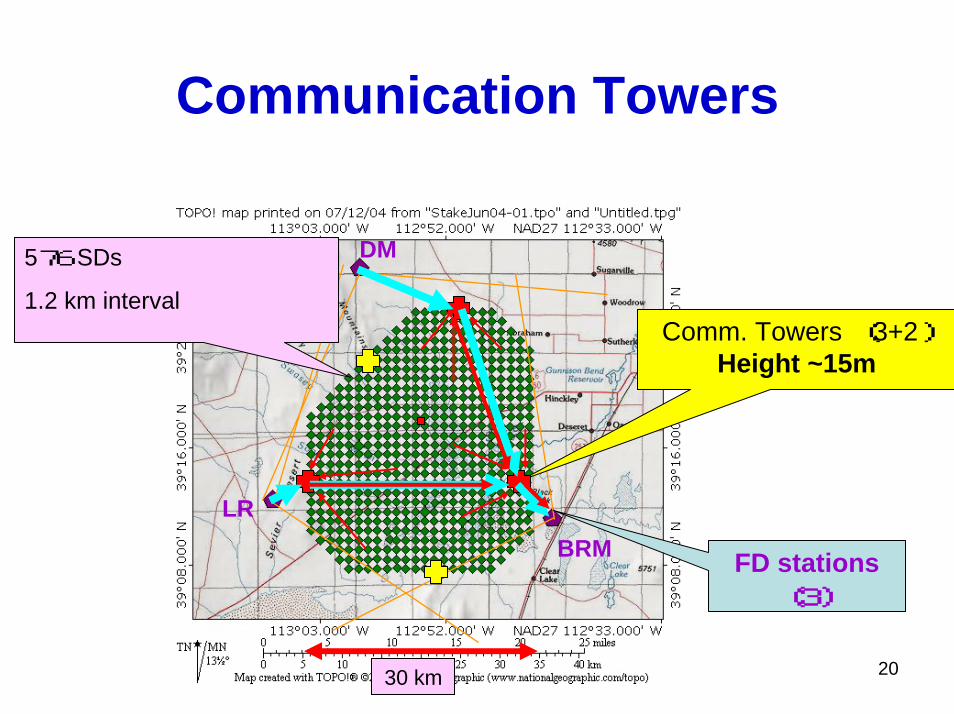
Communication Towers
2030 km
576 SDs
1.2 km interval
FD stations(3)
Comm. Towers (3+2)Height ~15m
DM
LRBRM
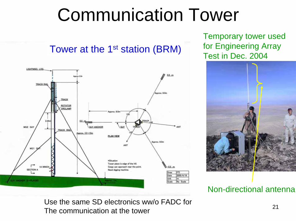
Communication TowerTemporary tower used for Engineering Array Test in Dec. 2004
Tower at the 1st station (BRM)
Use the same SD electronics ww/o FADC forThe communication at the tower
Non-directional antenna
21
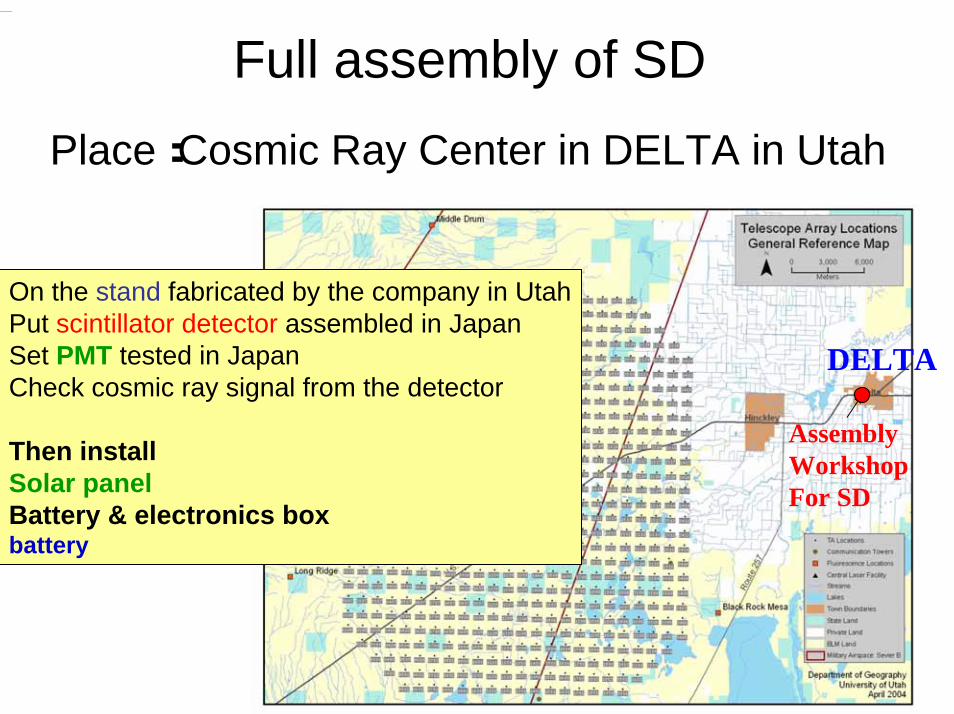
Full assembly of SDPlace:Cosmic Ray Center in DELTA in Utah
22
DELTA
AssemblyWorkshopFor SD
On the stand fabricated by the company in UtahPut scintillator detector assembled in JapanSet PMT tested in JapanCheck cosmic ray signal from the detector
Then installSolar panelBattery & electronics boxbattery
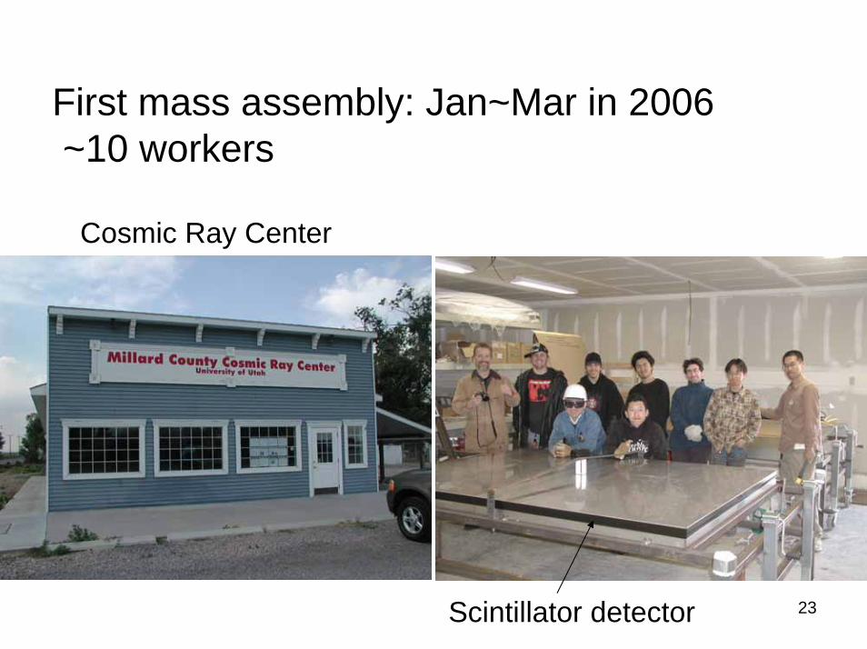
First mass assembly: Jan~Mar in 2006~10 workers
Cosmic Ray Center
Scintillator detector 23
24
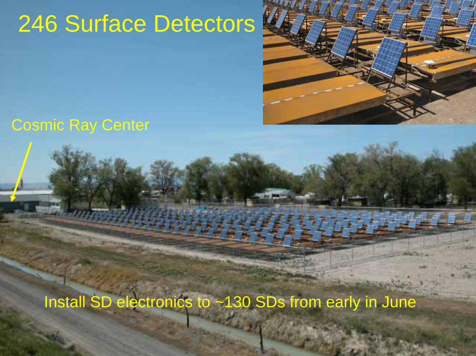
246 Surface Detectors
Cosmic Ray Center
Install SD electronics to ~130 SDs from early in June
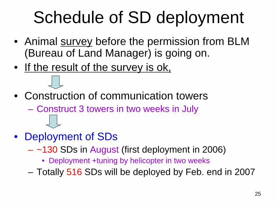
Schedule of SD deployment• Animal survey before the permission from BLM
(Bureau of Land Manager) is going on.• If the result of the survey is ok,
• Construction of communication towers– Construct 3 towers in two weeks in July
• Deployment of SDs– ~130 SDs in August (first deployment in 2006)
• Deployment +tuning by helicopter in two weeks– Totally 516 SDs will be deployed by Feb. end in 2007
25
26
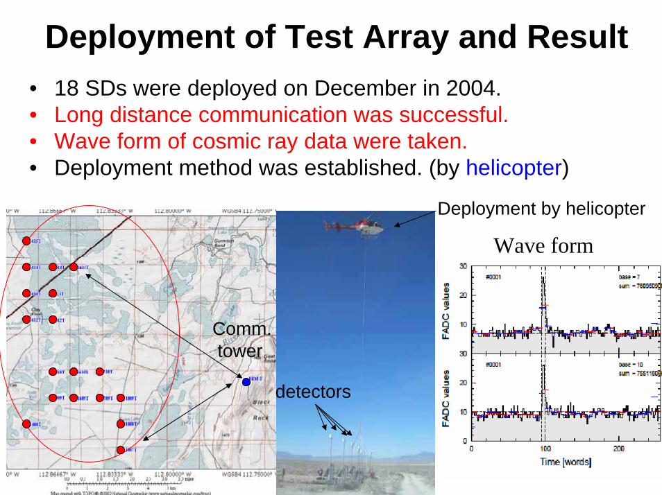
SD• 18 SDs were deployed on December in 2004.• Long distance communication was successful.• Wave form of cosmic ray data were taken.• Deployment method was established. (by helicopter)
Comm.tower
Deployment by helicopter
detectors
Wave form
Deployment of Test Array and Result
Fluorescence telescope
27
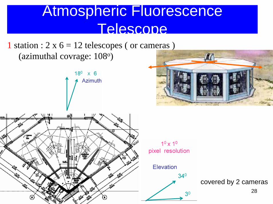
Atmospheric Fluorescence Telescope
28
1 station : 2 x 6 = 12 telescopes ( or cameras )(azimuthal covrage: 108o)
covered by 2 cameras
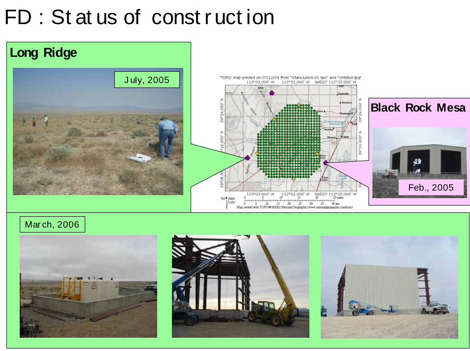
FD : Status of construction
29
Feb., 2005
July, 2005
Black Rock Mesa
Long Ridge
March, 2006
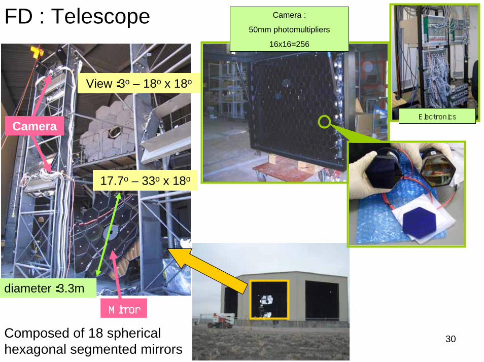
FD : Telescope
30
diameter:3.3m
View:3o – 18o x 18o
17.7o – 33o x 18o
Mirror
Camera
Camera :
50mm photomultipliers
16x16=256
Electronics
Composed of 18 sphericalhexagonal segmented mirrors
31
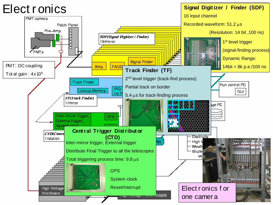
Electronics
PMT: DC coupling
Total gain : 4x10⁶
Electronics for one camera
Pre Amp.Signal Digitizer / Finder (SDF)
1st level trigger
(signal-finding process)
Dynamic Range:
14bit = 8k p.e./100 ns
16 input channel
Recorded waveform: 51.2 µs
(Resolution: 14 bit ,100 ns)
Track Finder (TF)2nd level trigger (track-find process)
Partial track on border
5.4 µs for track-finding process
Central Trigger Distributor (CTD)
Inter-mirror trigger, External trigger
Distribute Final Trigger to all the telescopes
Total triggering process time: 9.8 µs
GPS
System clock
Reset/Interrupt
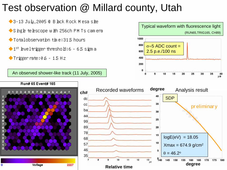
Test observation @ Millard county, Utah
32
An observed shower-like track (11 July, 2005)
ch# Recorded waveforms
Relative time
dcccbaaa99897868574635
Typical waveform with fluorescence light(RUN65,TRIG165, CH89)
3-13 July, 2005 @ Black Rock Mesa site
Single telescope with 256ch PMTs camera
Total observation time: 31.5 hours
1st level trigger threshold: 6 - 6.5 sigma
Trigger rate: 0.6 - 1.5 Hz
σ=5 ADC count = 2.5 p.e./100 ns
preliminarySDP
logE(eV) = 18.05
Xmax = 674.9 g/cm2
θ = 46.2o
Analysis resultdegree
degree
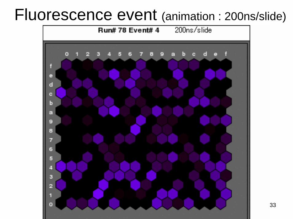
Fluorescence event (animation : 200ns/slide)
33
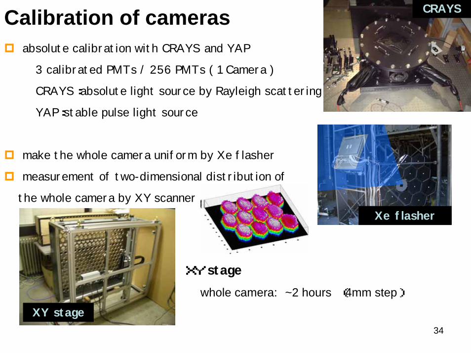
absolute calibration with CRAYS and YAP
3 calibrated PMTs / 256 PMTs ( 1 Camera )
CRAYS:absolute light source by Rayleigh scattering
YAP:stable pulse light source
make the whole camera uniform by Xe flasher
measurement of two-dimensional distribution of
the whole camera by XY scanner
Calibration of cameras CRAYS
XY stagewhole camera: ~2 hours (4mm step)
XY stage
Xe flasher
34
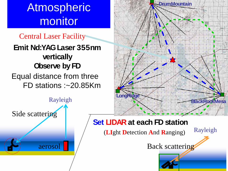
BlackRockMesaBlackRockMesaLongRidgeLongRidge
Atmospheric monitor
DrumMountainDrumMountain
Equal distance from three FD stations :~20.85Km
35
Set LIDAR at each FD station
Emit Nd:YAG Laser 355nmvertically
Observe by FD
Central Laser Facility
Rayleigh
aerosol
Rayleigh
Side scattering
Back scattering
(LIght Detection And Ranging)
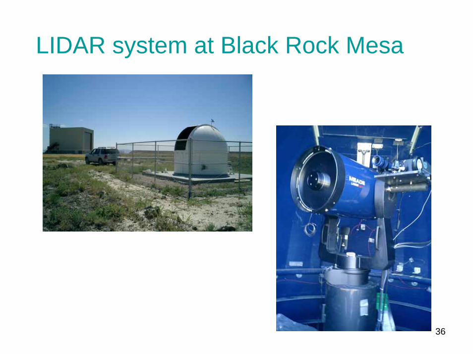
LIDAR system at Black Rock Mesa
36
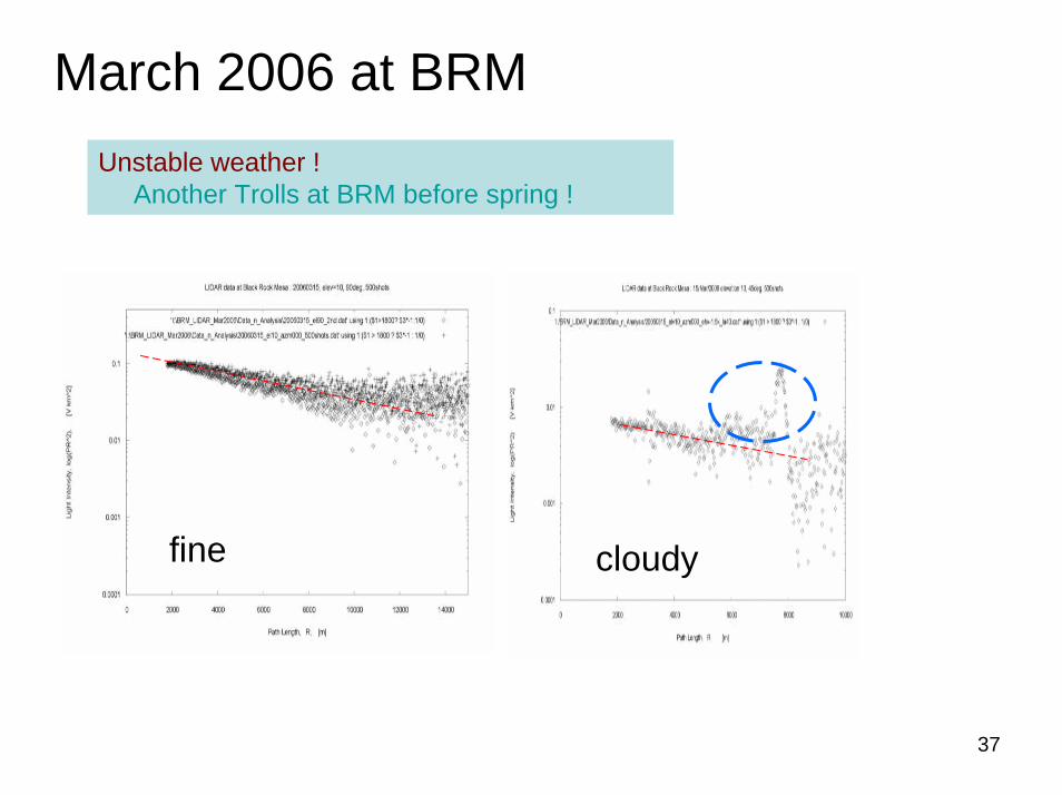
March 2006 at BRMUnstable weather !
Another Trolls at BRM before spring !
cloudyfine
37
38
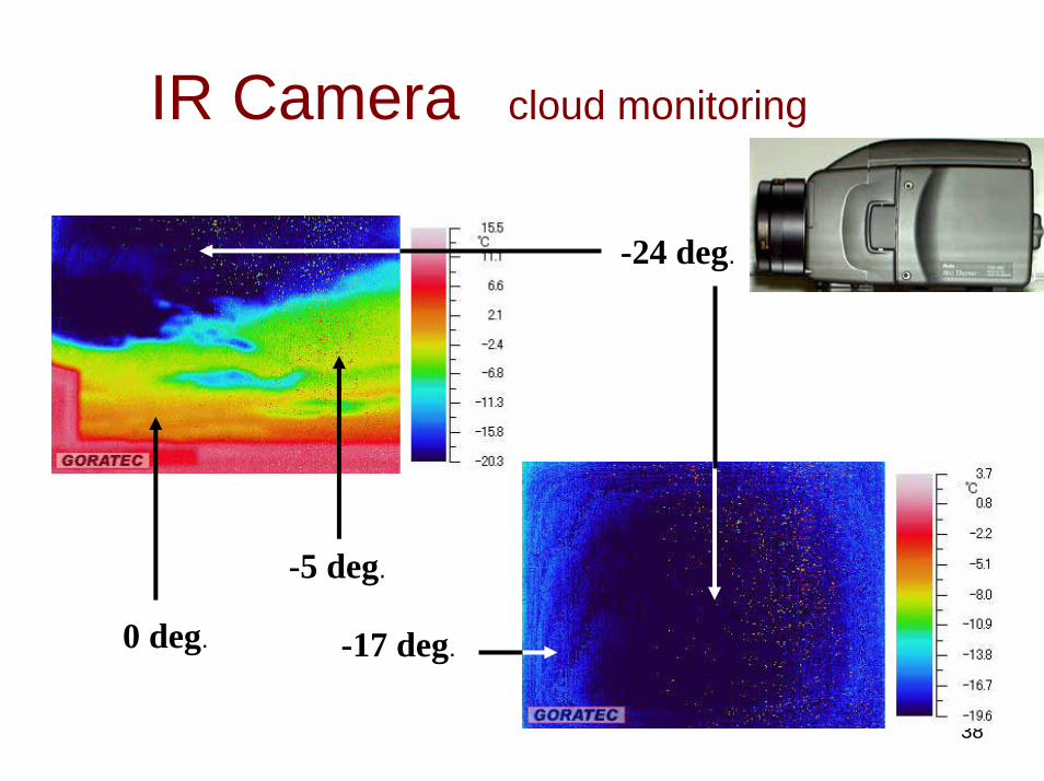
IR Camera cloud monitoring
-24 deg.
0 deg. -17 deg.
-5 deg.
Schedule of FD
• BRM (1st station: southeast)– Mirror setting in July– Camera setting in August– Tuning and test of observation
• LR (2nd station: southwest)– The building of the station: complete in May– 1 telescope setting in May– 6 telescope structures: complete by fall
• Comlete all setup and test by Mar 200739
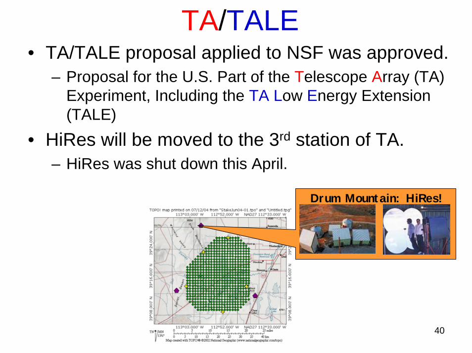
TA/TALE• TA/TALE proposal applied to NSF was approved.
– Proposal for the U.S. Part of the Telescope Array (TA) Experiment, Including the TA Low Energy Extension (TALE)
• HiRes will be moved to the 3rd station of TA.– HiRes was shut down this April.
Drum Mountain: HiRes!
40

The End
41


![Design studies for a multi-TeV [gamma]-ray telescope array ... · Telescopes (IACTs) to detect multi-TeV (E > 1012 eV) γ-ray sources. The array consists of 5 telescopes in a square](https://static.fdocument.org/doc/165x107/5e6a14251a4b8b3dc5439a35/design-studies-for-a-multi-tev-gamma-ray-telescope-array-telescopes-iacts.jpg)