Phased Array Feed Design - Australia Telescope National ... · • Why phased array feeds (PAFs)...
15
Phased Array Feed Design Stuart Hay 23 October 2009
Transcript of Phased Array Feed Design - Australia Telescope National ... · • Why phased array feeds (PAFs)...
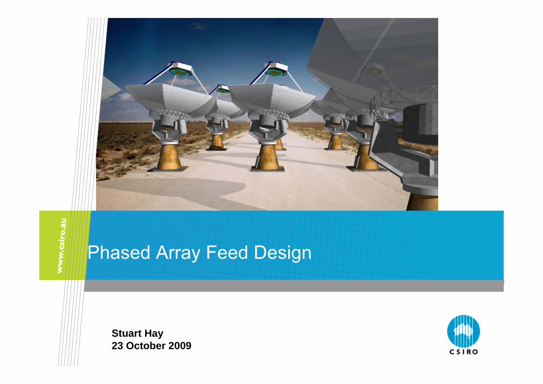
Phased Array Feed Design
Stuart Hay23 October 2009
CSIRO. Connected Array CBFM
Outline
• Why phased array feeds (PAFs) for radioastronomy? • General features and issues of PAF approach• Connected-array PAF approach in ASKAP
CSIRO. Connected Array CBFM
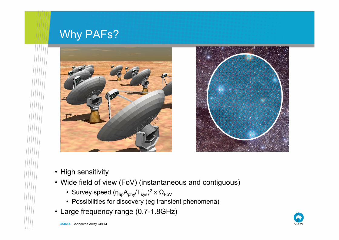
Why PAFs?
• High sensitivity • Wide field of view (FoV) (instantaneous and contiguous)
• Survey speed (ηapAphy/Tsys)2 x ΩFoV
• Possibilities for discovery (eg transient phenomena) • Large frequency range (0.7-1.8GHz)
CSIRO. Connected Array CBFM
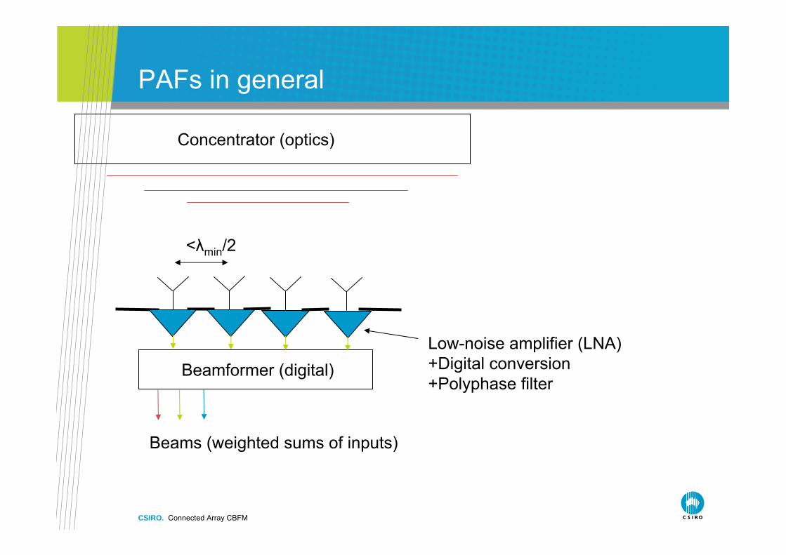
PAFs in general
Concentrator (optics)
Low-noise amplifier (LNA) +Digital conversion +Polyphase filter
Beams (weighted sums of inputs)
Beamformer (digital)
<λmin/2
CSIRO. Connected Array CBFM
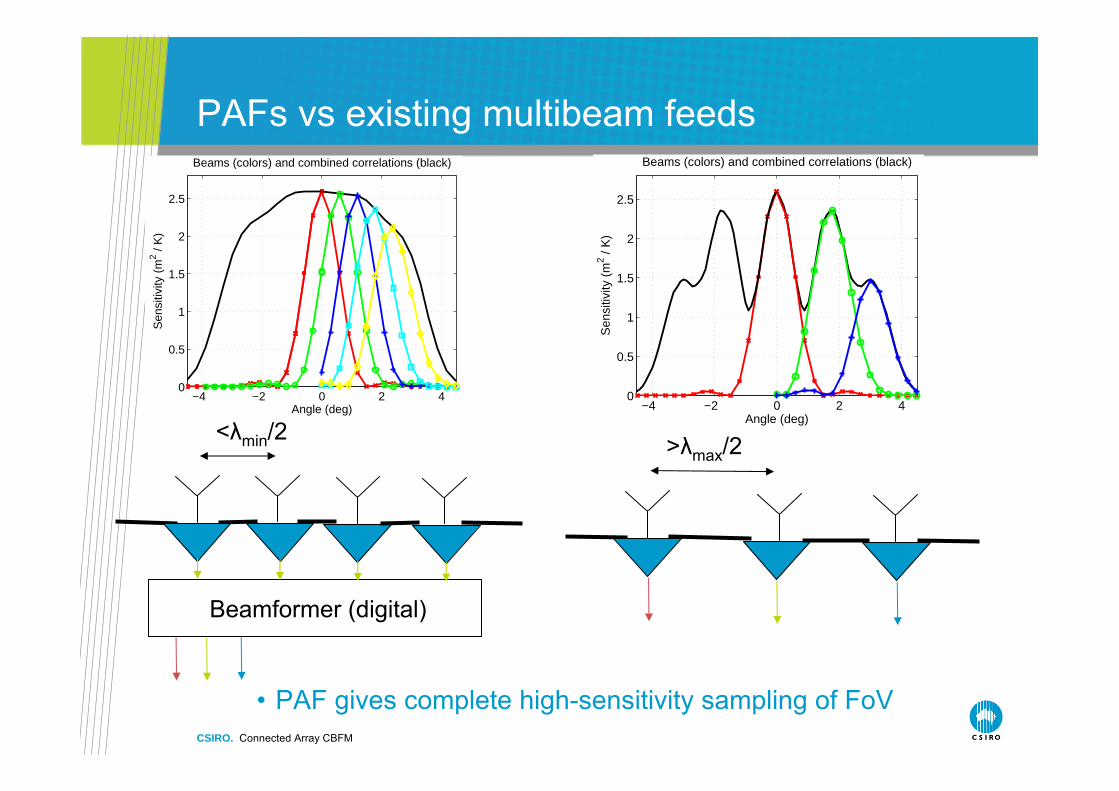
PAFs vs existing multibeam feeds
• PAF gives complete high-sensitivity sampling of FoV
Beamformer (digital)
<λmin/2 >λmax/2
−4 −2 0 2 40
0.5
1
1.5
2
2.5
Angle (deg)
Sen
sitiv
ity (
m2 /
K)
Beams (colors) and combined correlations (black)
−4 −2 0 2 40
0.5
1
1.5
2
2.5
Angle (deg)
Sen
sitiv
ity (
m2 /
K)
Beams (colors) and combined correlations (black)
CSIRO. Connected Array CBFM
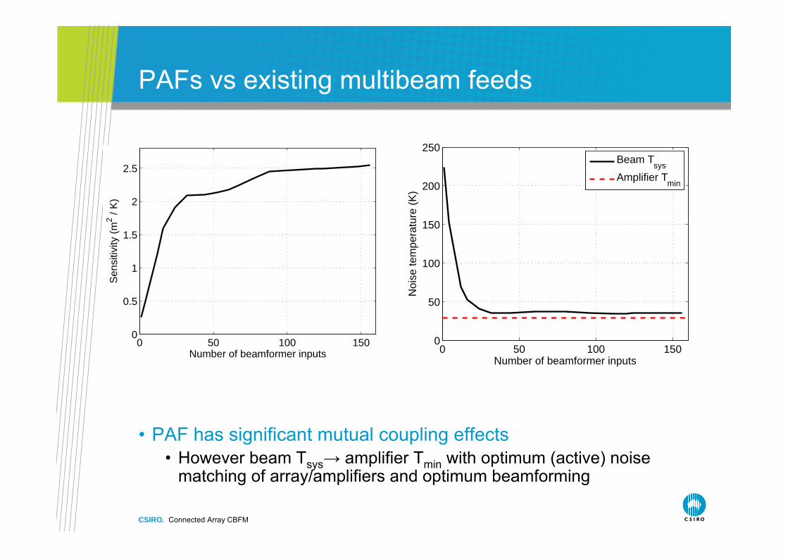
PAFs vs existing multibeam feeds
• PAF has significant mutual coupling effects• However beam Tsys→ amplifier Tmin with optimum (active) noise
matching of array/amplifiers and optimum beamforming
0 50 100 1500
0.5
1
1.5
2
2.5
Number of beamformer inputs
Sen
sitiv
ity (
m2 /
K)
0 50 100 1500
50
100
150
200
250
Number of beamformer inputs
Noi
se te
mpe
ratu
re (
K)
Beam Tsys
Amplifier Tmin
CSIRO. Connected Array CBFM
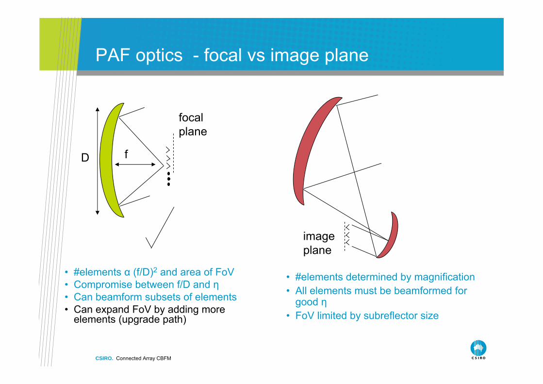
PAF optics - focal vs image plane
• #elements determined by magnification• All elements must be beamformed for
good η• FoV limited by subreflector size
focal plane
imageplane
fD
• #elements α (f/D)2 and area of FoV• Compromise between f/D and η• Can beamform subsets of elements• Can expand FoV by adding more
elements (upgrade path)
CSIRO. Connected Array CBFM
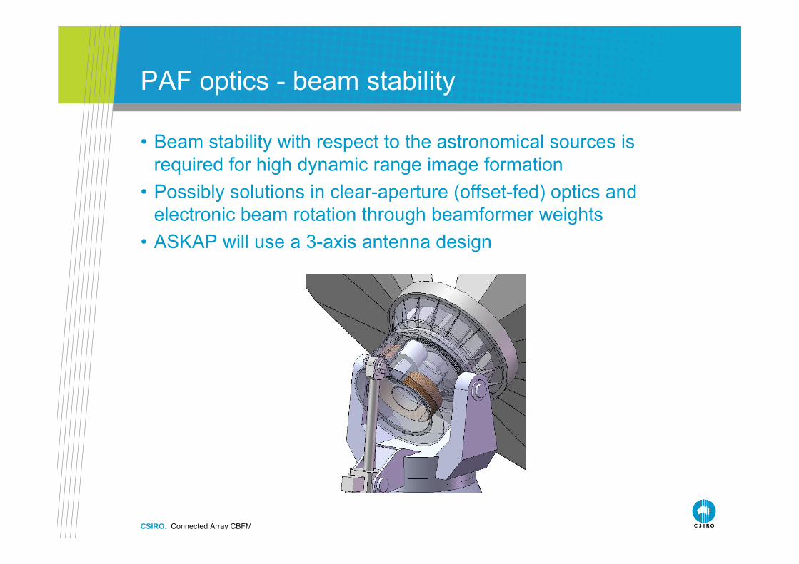
PAF optics - beam stability
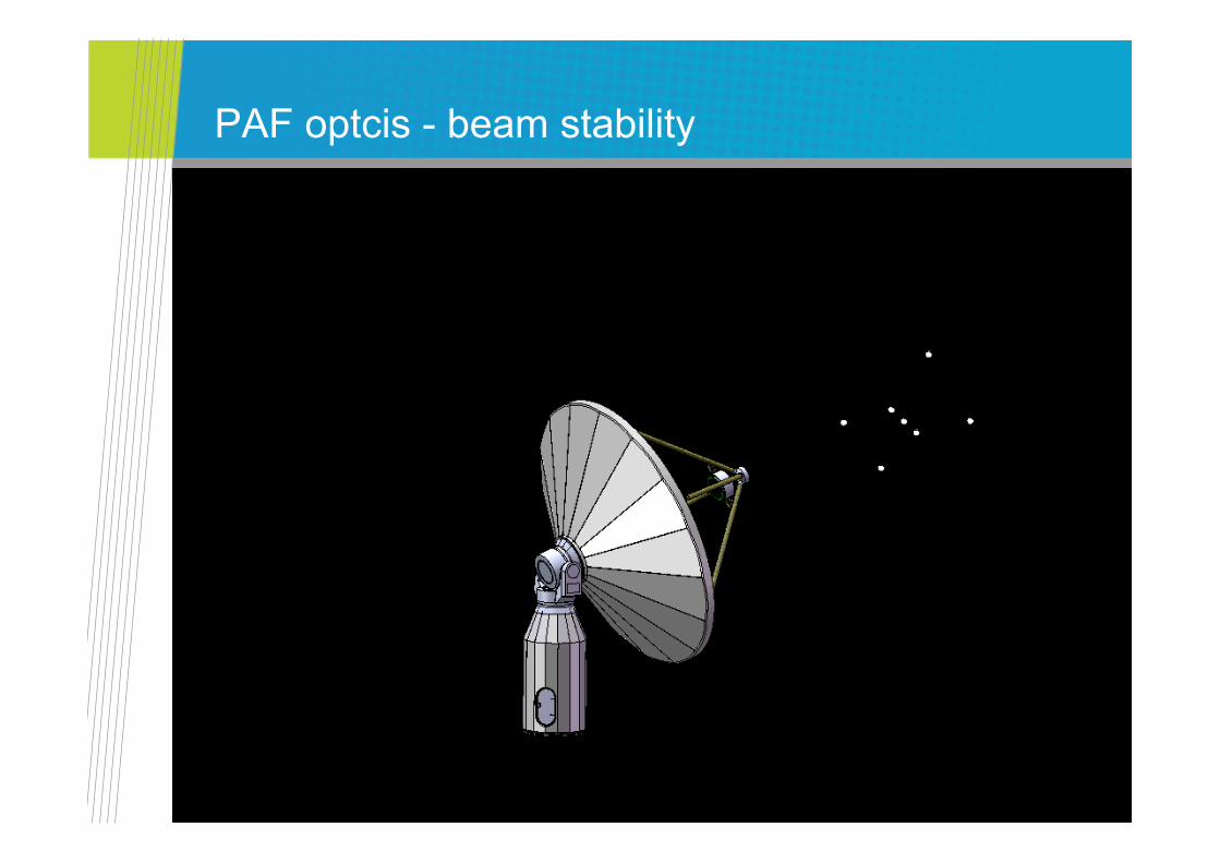
• Beam stability with respect to the astronomical sources is required for high dynamic range image formation
• Possibly solutions in clear-aperture (offset-fed) optics and electronic beam rotation through beamformer weights
• ASKAP will use a 3-axis antenna design
CSIRO. Connected Array CBFM
PAF optcis - beam stability
CSIRO. Connected Array CBFM
PAF/LNA issues
• Uncooled LNAs with Tmin in 20-40K range over 0.5-2GHz have been developed
• Tsys/ηap < 70K realistic target that would make PAFs competitive• Cooling PAFs is not straightforward
• Many coupled elements distributed over large area• However should be further considered
• Differential LNAs and LNAs with >50Ω noise-match impedance are desired for some PAF designs
• Reduce balun loss• Minimize LNA Tmin
• LNA modelling and measurements require further work
CSIRO. Connected Array CBFM
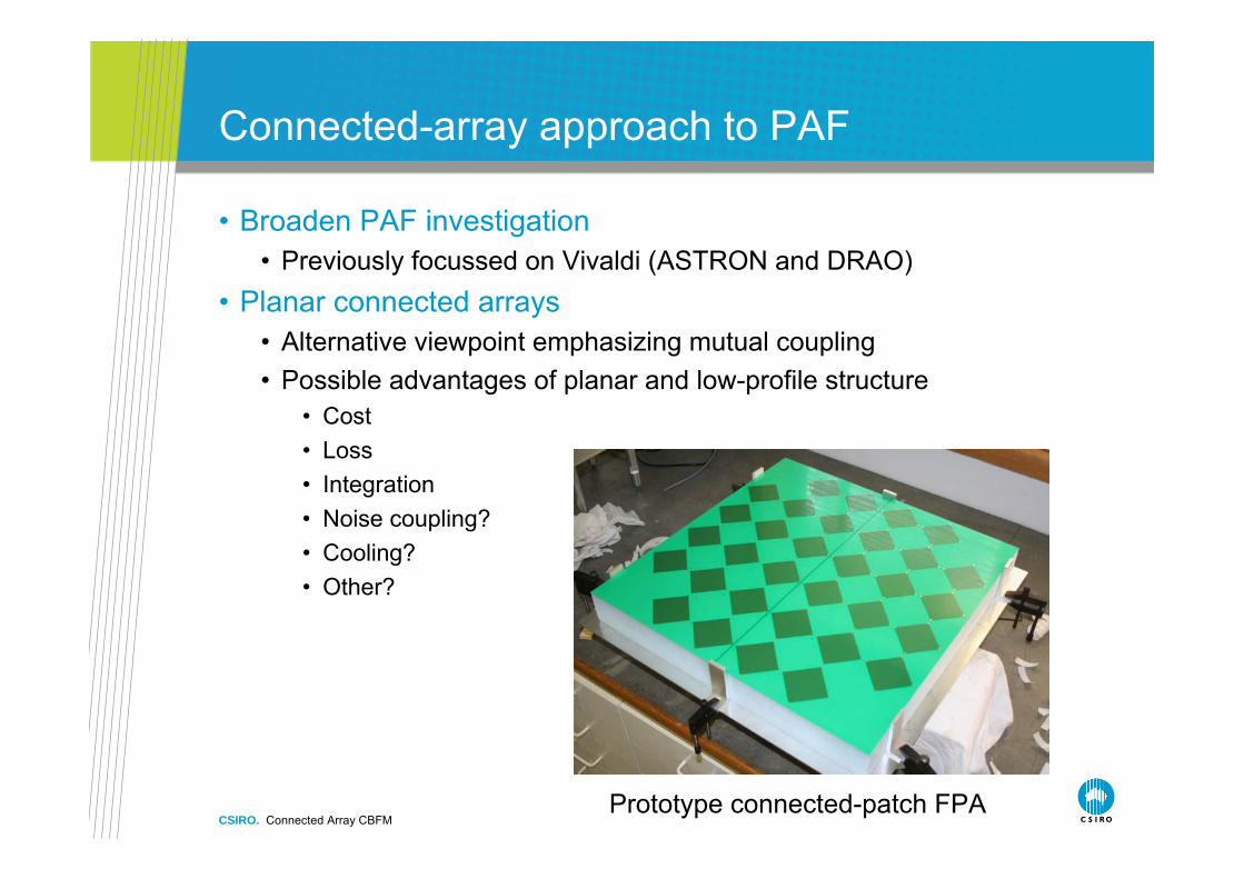
Connected-array approach to PAF
• Broaden PAF investigation• Previously focussed on Vivaldi (ASTRON and DRAO)
• Planar connected arrays• Alternative viewpoint emphasizing mutual coupling• Possible advantages of planar and low-profile structure
• Cost• Loss• Integration• Noise coupling?• Cooling?• Other?
Prototype connected-patch FPA
CSIRO. Connected Array CBFM
Connected-array approach
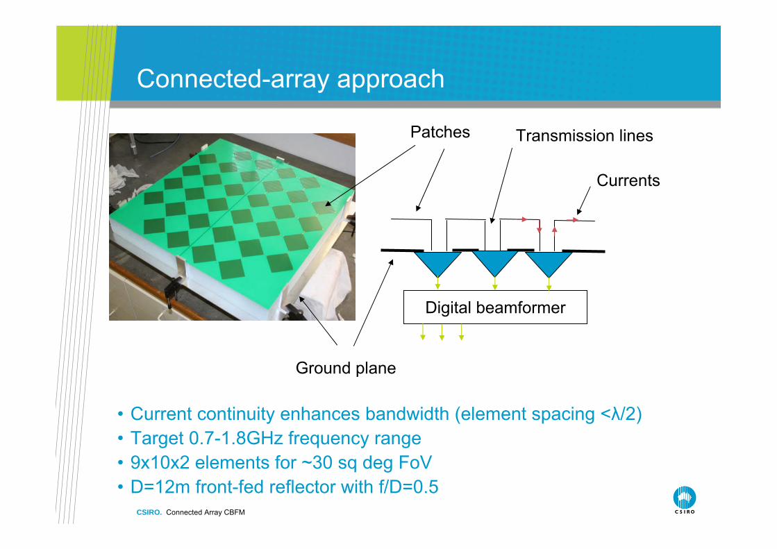
• Current continuity enhances bandwidth (element spacing <λ/2)• Target 0.7-1.8GHz frequency range• 9x10x2 elements for ~30 sq deg FoV• D=12m front-fed reflector with f/D=0.5
Patches Transmission lines
Ground plane
Digital beamformer
Currents
CSIRO. Connected Array CBFM
Approach to the design
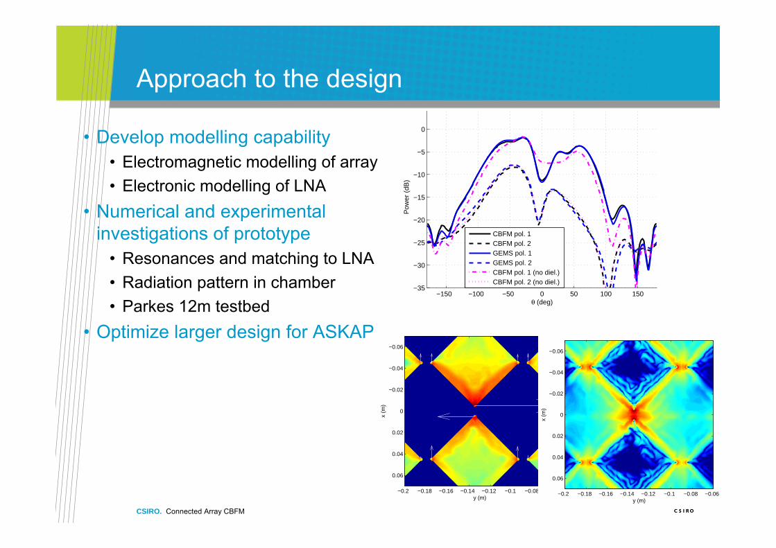
• Develop modelling capability• Electromagnetic modelling of array• Electronic modelling of LNA
• Numerical and experimental investigations of prototype
• Resonances and matching to LNA • Radiation pattern in chamber• Parkes 12m testbed
• Optimize larger design for ASKAP
−150 −100 −50 0 50 100 150−35
−30
−25
−20
−15
−10
−5
0
θ (deg)
Pow
er (
dB)
CBFM pol. 1CBFM pol. 2GEMS pol. 1GEMS pol. 2CBFM pol. 1 (no diel.)CBFM pol. 2 (no diel.)
y (m)
x (m
)
−0.2 −0.18 −0.16 −0.14 −0.12 −0.1 −0.08 −0.06
−0.06
−0.04
−0.02
0
0.02
0.04
0.06
−50
−40
−30
−20
−10
0
10
20
30
y (m)
x (m
)
−0.2 −0.18 −0.16 −0.14 −0.12 −0.1 −0.08 −0.06
−0.06
−0.04
−0.02
0
0.02
0.04
0.06
CSIRO. Connected Array CBFM
Connected-array matching
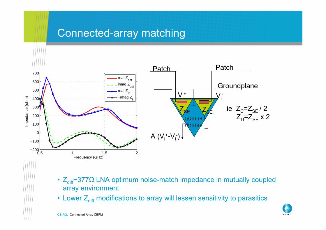
• Zdiff~377Ω LNA optimum noise-match impedance in mutually coupled array environment
• Lower Zdiff modifications to array will lessen sensitivity to parasitics
0.5 1 1.5 2−200
−100
0
100
200
300
400
500
600
700
Frequency (GHz)
Impe
danc
e (o
hm)
real Zopt
imag Zopt
real Zin
−imag Zin
ZSE ZSE
Vi+ Vi
-
Patch Patch
A (Vi+-Vi
-)
Groundplane
ie ZC=ZSE / 2ZD=ZSE x 2

Contact UsPhone: 1300 363 400 or +61 3 9545 2176
Email: [email protected] Web: www.csiro.au
Thank you
CSIRO ICT CentreStuart Hay
Phone: +61 2 9372 4288Email: [email protected]: www.csiro.au/group


![Design studies for a multi-TeV [gamma]-ray telescope array ... · Telescopes (IACTs) to detect multi-TeV (E > 1012 eV) γ-ray sources. The array consists of 5 telescopes in a square](https://static.fdocument.org/doc/165x107/5e6a14251a4b8b3dc5439a35/design-studies-for-a-multi-tev-gamma-ray-telescope-array-telescopes-iacts.jpg)


![Άσκηση 1η –Μέρος Α - NTUA...Άσκηση1η–Μέρος Α int array[100]; int *p, N; p = &array[8]; while (*p != 0){if (*p < 100) *p = *p % N; else *p = *p / N; p++;}](https://static.fdocument.org/doc/165x107/61213bb539ee736c47746d04/ff-1-aoe-ff1aoe-int-array100.jpg)