Rolando Guidelli*, Richard G. Compton, Juan M. Feliu, … · is the anodic Tafel slope. It should...
14
DOI 10.1515/pac-2014-5026 Pure Appl. Chem. 2014; 86(2): 245–258 IUPAC Technical Report Rolando Guidelli*, Richard G. Compton, Juan M. Feliu, Eliezer Gileadi, Jacek Lipkowski, Wolfgang Schmickler and Sergio Trasatti Defining the transfer coefficient in electrochemistry: An assessment (IUPAC Technical Report) 1 Abstract: The transfer coefficient α is a quantity that is commonly employed in the kinetic investigation of electrode processes. In the 3 rd edition of the IUPAC Green Book, the cathodic transfer coefficient α c is defined as –(RT/nF)(dlnk c /dE), where k c is the electroreduction rate constant, E is the applied potential, and R, T, and F have their usual significance. This definition is equivalent to the other, -(RT/nF)(dln|j c |/dE), where j c is the cathodic current density corrected for any changes in the reactant concentration at the electrode surface with respect to its bulk value. The anodic transfer coefficient α a is defined similarly, by simply replacing j c with the anodic current density j a and the minus sign with the plus sign. It is shown that this definition applies only to an electrode reaction that consists of a single elementary step involving the simultaneous uptake of n electrons from the electrode in the case of α c , or their release to the electrode in the case of α a . However, an elementary step involving the simultaneous release or uptake of more than one electron is regarded as highly improbable in view of the absolute rate theory of electron transfer of Marcus; the hardly satisfiable requirements for the occurrence of such an event are examined. Moreover, the majority of electrode reactions do not consist of a single elementary step; rather, they are multistep, multi-electron processes. The uncriti- cal application of the above definitions of α c and α a has led researchers to provide unwarranted mechanistic interpretations of electrode reactions. In fact, the only directly measurable experimental quantity is dln|j|/ dE, which can be made dimensionless upon multiplication by RT/F, yielding (RT/F)(dln|j|/dE). One common source of misinterpretation consists in setting this experimental quantity equal to αn, according to the above definition of the transfer coefficient, and in trying to estimate n from αn, upon ascribing an arbitrary value to α, often close to 0.5. The resulting n value is then identified with the number of electrons involved in a hypo- thetical rate-determining step or with that involved in the overall electrode reaction. A few examples of these unwarranted mechanistic interpretations are reported. In view of the above considerations, it is proposed to define the cathodic and anodic transfer coefficients by the quantities α c = –(RT/F)(dln|j c |/dE) and α a = (RT/F) (dlnj a /dE), which are independent of any mechanistic consideration. Keywords: electrode kinetics; IUPAC Physical and Biophysical Chemistry Division; reorganization energy; symmetry factor; Tafel slope; transfer coefficient. 1 Sponsoring body: IUPAC Physical and Biophysical Chemistry Division: see more details on p. 257. *Corresponding author: Rolando Guidelli, Department of Chemistry “Ugo Schiff”, University of Florence, Via della Lastruccia 3, 50014 Sesto Fiorentino (Firenze), Italy, e-mail: [email protected] Richard G. Compton: Department of Chemistry, University of Oxford, Physical and Theoretical Chemistry Laboratory, South Parks Road, Oxford OX1 3QZ, UK Juan M. Feliu: Department of Physical Chemistry, University of Alicante, Ap. De Correos, 99, 03080, Alicante, Spain Eliezer Gileadi: School of Chemistry, Faculty of Exact Sciences, University of Tel-Aviv, Tel-Aviv, Israel Jacek Lipkowski: Department of Chemistry and Biochemistry, University of Guelph, 50 Stone Road East, Guelph, Ontario, N1G 2W1, Canada Wolfgang Schmickler: Institute of Theoretical Chemistry, University of Ulm, Albert Einstein Allee 11, D-89069 Ulm, Germany Sergio Trasatti: Department of Chemistry, University of Milan, Via Camillo Golgi 19, 20133 Milan, Italy © 2014 IUPAC & De Gruyter
Transcript of Rolando Guidelli*, Richard G. Compton, Juan M. Feliu, … · is the anodic Tafel slope. It should...
DOI 10.1515/pac-2014-5026 Pure Appl. Chem. 2014; 86(2): 245–258
IUPAC Technical Report
Rolando Guidelli*, Richard G. Compton, Juan M. Feliu, Eliezer Gileadi, Jacek Lipkowski, Wolfgang Schmickler and Sergio TrasattiDefining the transfer coefficient in electrochemistry: An assessment (IUPAC Technical Report)1
Abstract: The transfer coefficient α is a quantity that is commonly employed in the kinetic investigation of electrode processes. In the 3rd edition of the IUPAC Green Book, the cathodic transfer coefficient αc is defined as –(RT/nF)(dlnkc/dE), where kc is the electroreduction rate constant, E is the applied potential, and R, T, and F have their usual significance. This definition is equivalent to the other, -(RT/nF)(dln|jc|/dE), where jc is the cathodic current density corrected for any changes in the reactant concentration at the electrode surface with respect to its bulk value. The anodic transfer coefficient αa is defined similarly, by simply replacing jc with the anodic current density ja and the minus sign with the plus sign. It is shown that this definition applies only to an electrode reaction that consists of a single elementary step involving the simultaneous uptake of n electrons from the electrode in the case of αc, or their release to the electrode in the case of αa. However, an elementary step involving the simultaneous release or uptake of more than one electron is regarded as highly improbable in view of the absolute rate theory of electron transfer of Marcus; the hardly satisfiable requirements for the occurrence of such an event are examined. Moreover, the majority of electrode reactions do not consist of a single elementary step; rather, they are multistep, multi-electron processes. The uncriti-cal application of the above definitions of αc and αa has led researchers to provide unwarranted mechanistic interpretations of electrode reactions. In fact, the only directly measurable experimental quantity is dln|j|/dE, which can be made dimensionless upon multiplication by RT/F, yielding (RT/F)(dln|j|/dE). One common source of misinterpretation consists in setting this experimental quantity equal to αn, according to the above definition of the transfer coefficient, and in trying to estimate n from αn, upon ascribing an arbitrary value to α, often close to 0.5. The resulting n value is then identified with the number of electrons involved in a hypo-thetical rate-determining step or with that involved in the overall electrode reaction. A few examples of these unwarranted mechanistic interpretations are reported. In view of the above considerations, it is proposed to define the cathodic and anodic transfer coefficients by the quantities αc = –(RT/F)(dln|jc|/dE) and αa = (RT/F)(dlnja/dE), which are independent of any mechanistic consideration.
Keywords: electrode kinetics; IUPAC Physical and Biophysical Chemistry Division; reorganization energy; symmetry factor; Tafel slope; transfer coefficient.
1Sponsoring body: IUPAC Physical and Biophysical Chemistry Division: see more details on p. 257.*Corresponding author: Rolando Guidelli, Department of Chemistry “Ugo Schiff”, University of Florence, Via della Lastruccia 3, 50014 Sesto Fiorentino (Firenze), Italy, e-mail: [email protected] G. Compton: Department of Chemistry, University of Oxford, Physical and Theoretical Chemistry Laboratory, South Parks Road, Oxford OX1 3QZ, UKJuan M. Feliu: Department of Physical Chemistry, University of Alicante, Ap. De Correos, 99, 03080, Alicante, SpainEliezer Gileadi: School of Chemistry, Faculty of Exact Sciences, University of Tel-Aviv, Tel-Aviv, IsraelJacek Lipkowski: Department of Chemistry and Biochemistry, University of Guelph, 50 Stone Road East, Guelph, Ontario, N1G 2W1, CanadaWolfgang Schmickler: Institute of Theoretical Chemistry, University of Ulm, Albert Einstein Allee 11, D-89069 Ulm, GermanySergio Trasatti: Department of Chemistry, University of Milan, Via Camillo Golgi 19, 20133 Milan, Italy
© 2014 IUPAC & De Gruyter
246 R. Guidelli et al.: Transfer coefficient: An assessment
1 Historical overviewThe transfer coefficient, α, was originally introduced in electrochemistry by Butler [1] and by Erdey-Gruz and Volmer [2]; it was defined as the fraction of the electrostatic potential energy affecting the reduction rate in an electrode reaction, with the remaining fraction (1 – α) affecting the corresponding oxidation rate. For a generic cathodic reaction
O e Rn+ → (1)
the electrostatic potential energy is given by nFΔφ, where Δφ is the potential difference across the electrified interface, which differs from the applied electric potential E by a constant depending on the choice of the reference electrode. In this connection, it should be noted that electrons in a metal differ from the molecular species that are dealt with in chemical kinetics because they satisfy the Fermi statistics instead of the Boltz-mann statistics. While the latter statistics lead to an expression of the electrochemical potential of the species that includes a term proportional to the logarithm of its concentration, this is not the case for the Fermi sta-tistics. Differently stated, there is no sense in referring to an “electron concentration” in a metal. This makes a major difference between electrochemical kinetics and chemical kinetics. Inserting this expression into the equation of the absolute reaction rate theory yields the following relationship between the cathodic current density jc and the applied potential E:
c cexp( / )j nFE RTα∝ − (2)
where F, R, and T have their usual significance. This expression holds in the absence of depletion and diffuse-layer effects that may alter the reactant concentration at the electrode surface with respect to its bulk value. The dimensionless “cathodic” transfer coefficient αc is immediately obtained from the slope of the plot of ln |jc| against E:
c c( / )( dln| | / d )RT nF j Eα =− (3)
The derivative dE/dln|jc| is referred to as the cathodic Tafel slope. Incidentally, here and in the following the symbol ln|jc| implies that the argument of the logarithm is of dimension one, obtained by division with the corresponding unit, e.g., ln|jc| meaning ln(|jc|/A m–2), and similarly for the other quantities ja, ka, and kc. By analogous considerations, for an anodic reaction
R O ne→ + (4)
we have
a aexp( / )j nFE RTα∝ (5)
and
a a( / )( dln / d )RT nF j Eα = (6)
where dE/dlnja is the anodic Tafel slope. It should be borne in mind that eqs. 3 and 6 hold strictly only if the cathodic reaction of eq. 1 and the anodic reaction of eq. 4 consist of a single elementary step involving the simultaneous release or uptake of n electrons by the electrode, respectively. The notations of eqs. 2, 3, 5, and 6 have been used in a number of textbooks.
In the proximity of the equilibrium potential, Eeq, of a redox couple O/R, both the cathodic and the anodic current densities contribute to the net current density j, which is given by the sum of the two:
a c a a c c[ R] exp( / ) [ O] exp( / )j j j nFk nFE RT nFk nFE RTα α= + = − − (7)
R. Guidelli et al.: Transfer coefficient: An assessment 247
Here, ka and kc are the anodic and cathodic rate constants; the concentrations between square brack-ets are “volume concentrations on the electrode surface”, which can be expressed in mol·m–3 units; conse-quently, the rate constants ka and kc can be expressed in m3·mol–1·s–1 units. Under equilibrium conditions, j equals zero, yielding
0
a a eq c c eq[ R] exp( / ) [ O] exp( / )j nFk nFE RT nFk nFE RTα α= = −
(8)
or
a c c a eq[ O] / [ R] ( / ) exp[( ) / ]k k nFE RTα α= + (9)
In eq. 8, Eeq is the equilibrium potential and j0, called the exchange current density, is the common absolute value of the anodic and cathodic current densities, when they match at Eeq. Since at equilibrium the Nernst equation applies, from eq. 9 it follows that (αc + αa) = 1 and ka/kc = exp(-nFE°/RT), where E° is the formal potential of the O/R couple. Combining eqs. 7 and 8, we obtain the so-called Butler–Volmer equation
0
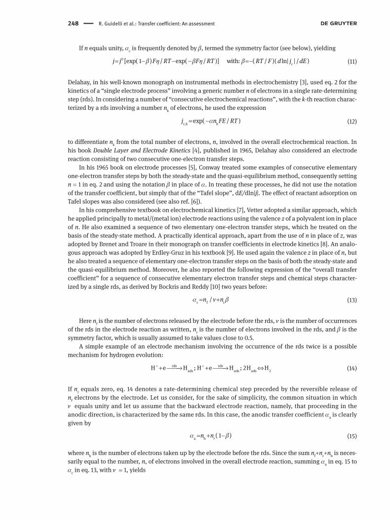
c c eq[exp( 1 ) / exp( / )] with:j j nF RT nF RT E Eα η α η η= − − − ≡ −
(10)
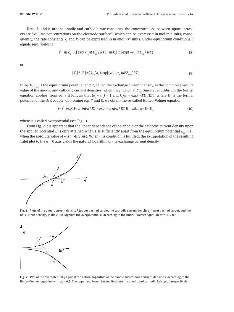
where η is called overpotential (see Fig. 1).From Fig. 2 it is apparent that the linear dependence of the anodic or the cathodic current density upon
the applied potential E is only attained when E is sufficiently apart from the equilibrium potential Eeq, i.e., when the absolute value of η is > > RT/(nF). When this condition is fulfilled, the extrapolation of the resulting Tafel plot to the η = 0 axis yields the natural logarithm of the exchange current density.
Fig. 2 Plot of the overpotential η against the natural logarithm of the anodic and cathodic current densities, according to the Butler–Volmer equation with αc = 0.5. The upper and lower dashed lines are the anodic and cathodic Tafel plot, respectively.
Fig. 1 Plots of the anodic current density ja (upper dashed curve), the cathodic current density jc (lower dashed curve), and the net current density j (solid curve) against the overpotential η, according to the Butler–Volmer equation with αc = 0.5.
248 R. Guidelli et al.: Transfer coefficient: An assessment
If n equals unity, αc is frequently denoted by β, termed the symmetry factor (see below), yielding
0 [exp( 1 ) / exp( / )] with: ( / )( ln| | / )cj j F RT F RT RT F d j dEβ η β η β= − − − =−
(11)
Delahay, in his well-known monograph on instrumental methods in electrochemistry [3], used eq. 2 for the kinetics of a “single electrode process” involving a generic number n of electrons in a single rate-determining step (rds). In considering a number of “consecutive electrochemical reactions”, with the k-th reaction charac-terized by a rds involving a number nk of electrons, he used the expression
c,k kexp( / )j n FE RTα∝ −
(12)
to differentiate nk from the total number of electrons, n, involved in the overall electrochemical reaction. In his book Double Layer and Electrode Kinetics [4], published in 1965, Delahay also considered an electrode reaction consisting of two consecutive one-electron transfer steps.
In his 1965 book on electrode processes [5], Conway treated some examples of consecutive elementary one-electron transfer steps by both the steady-state and the quasi-equilibrium method, consequently setting n = 1 in eq. 2 and using the notation β in place of α. In treating these processes, he did not use the notation of the transfer coefficient, but simply that of the “Tafel slope”, dE/dln|j|. The effect of reactant adsorption on Tafel slopes was also considered (see also ref. [6]).
In his comprehensive textbook on electrochemical kinetics [7], Vetter adopted a similar approach, which he applied principally to metal/(metal ion) electrode reactions using the valence z of a polyvalent ion in place of n. He also examined a sequence of two elementary one-electron transfer steps, which he treated on the basis of the steady-state method. A practically identical approach, apart from the use of n in place of z, was adopted by Brenet and Troare in their monograph on transfer coefficients in electrode kinetics [8]. An analo-gous approach was adopted by Erdley-Gruz in his textbook [9]. He used again the valence z in place of n, but he also treated a sequence of elementary one-electron transfer steps on the basis of both the steady-state and the quasi-equilibrium method. Moreover, he also reported the following expression of the “overall transfer coefficient” for a sequence of consecutive elementary electron transfer steps and chemical steps character-ized by a single rds, as derived by Bockris and Reddy [10] two years before:
c f r/n v nα β= + (13)
Here nf is the number of electrons released by the electrode before the rds, ν is the number of occurrences of the rds in the electrode reaction as written, nr is the number of electrons involved in the rds, and β is the symmetry factor, which is usually assumed to take values close to 0.5.
A simple example of an electrode mechanism involving the occurrence of the rds twice is a possible mechanism for hydrogen evolution:
rds rds
ads ads ads 2H e H ; H e H ; 2H H+ ++ → + → ⇔ (14)
If nr equals zero, eq. 14 denotes a rate-determining chemical step preceded by the reversible release of nf electrons by the electrode. Let us consider, for the sake of simplicity, the common situation in which ν equals unity and let us assume that the backward electrode reaction, namely, that proceeding in the anodic direction, is characterized by the same rds. In this case, the anodic transfer coefficient αa is clearly given by
a b ( 1 )rn nα β= + − (15)
where nb is the number of electrons taken up by the electrode before the rds. Since the sum nf+nr+nb is neces-sarily equal to the number, n, of electrons involved in the overall electrode reaction, summing αa in eq. 15 to αc in eq. 13, with ν = 1, yields
R. Guidelli et al.: Transfer coefficient: An assessment 249
c a nα α+ = (16)
In the more general case in which the rds occurs ν times in the electrode reaction, αc + αa is given by
c a /n vα α+ = (17)
The presence of ν in the denominator of eq. 17 can be easily understood by considering the electrode reaction of eq. 14 as an example. Here, the overall electrode reaction 2H+ + 2e → H2 involves two electrons, but a single rds involves only one. It must be stressed that eqs. 16 and 17 hold only if the forward and backward electrode reactions are characterized by the same rds, a situation that is not necessarily encountered when the negative overpotential for the cathodic process and the positive overpotential for the corresponding anodic process are relatively high [11].
The approach leading to eq. 13 is similar to that previously adopted by Mauser [12] in 1958. A treatment leading to an expression for α practically identical to eq. 13 was also developed by Gileadi, Kirowa-Eisner, and Penciner in their textbook on interfacial electrochemistry [13]. The expression of eq. 13 was subsequently reported again by Bockris, Reddy, and Gamboa-Aldeco [14] in an updated textbook on fundamentals of elect-rodics. A more general treatment of a sequence of elementary one-electron transfer steps and chemical steps was subsequently reported in an exhaustive monograph by Lefebvre [15].
Parsons’ recommendations in the framework of IUPAC’s Physical Chemistry Division [16, 17] deserve a special mention. They were based on his previous treatment of electrode kinetics published in 1961 [18]. To introduce the concept of electrode reaction orders, Parsons adopted a generic electrode reaction in which the cathodic partial current has the form
i,c
c c ii
( / )I n v FAk cν=− ∏
(18)
Here, A is the electrode area, n is the charge number of the electrode reaction “as written”, νi,c is the order of reaction for the i-th reactant of concentration ci, and ν is the “stoichiometric number giving the number of identical activated complexes formed and destroyed in the completion of the overall reaction as formu-lated with the transfer of n electrons”. With this expression of the cathodic current, its dependence upon the applied potential takes the form
c cexp( / )I nFE vRTα∝ − (19)
It follows that the transfer coefficient is given by
c c( / )( dln| | /d )RT nF I Eα ν=− (20)
The electrode reaction adopted by Parsons is not entirely general. In fact, Parsons stated that eq. 19 and the corresponding equation for the anodic current “are not general definitions since not all reaction rates can be expressed in this form. For example, the rate of a multistep reaction or a reaction involving adsorbed species may not be expressible in this form” [16]. In the majority of electrode reactions, n and ν are equal and cancel each other out in eq. 20, yielding
c c( / )( dln| | /d )RT F I Eα =− (21)
However, Parsons did not exclude the possibility for n and ν to be different, when he wrote [17]: “In general, the quantity n/ν is not arbitrary and is a true characteristic of the reaction kinetics. This ratio is the charge number that always appears in the kinetic equations. In principle, the use of ν could be avoided by choosing n so that ν is always unity but this requires more knowledge about the detailed kinetics of a complex reaction than is often available”.
250 R. Guidelli et al.: Transfer coefficient: An assessment
The definition of eq. 20 for the transfer coefficient αc recommended by Parsons was present in the first two editions of the IUPAC Green Book [19], but in the third edition the stoichiometric number ν was removed, yielding an equation substantially equivalent to eq. 3. This change was probably introduced to comply with the use of eqs. 2 and 3 made in many textbooks [20–22], including the first edition of Bard and Faulkner’s textbook [23], which reports kinetic equations relative to several electrochemical techniques. In the second, revised edition of this textbook [24], all these equations are applied to a single one-electron elementary step by replacing αn with α; moreover, an example of a multistep electrode process with a single one-electron rds and all other steps in quasi-equilibrium is examined, yielding an expression for α equal to that in eq. 13, with ν = 1 and nr = 1.
2 The simultaneous transfer of more than one electron is highly improbable
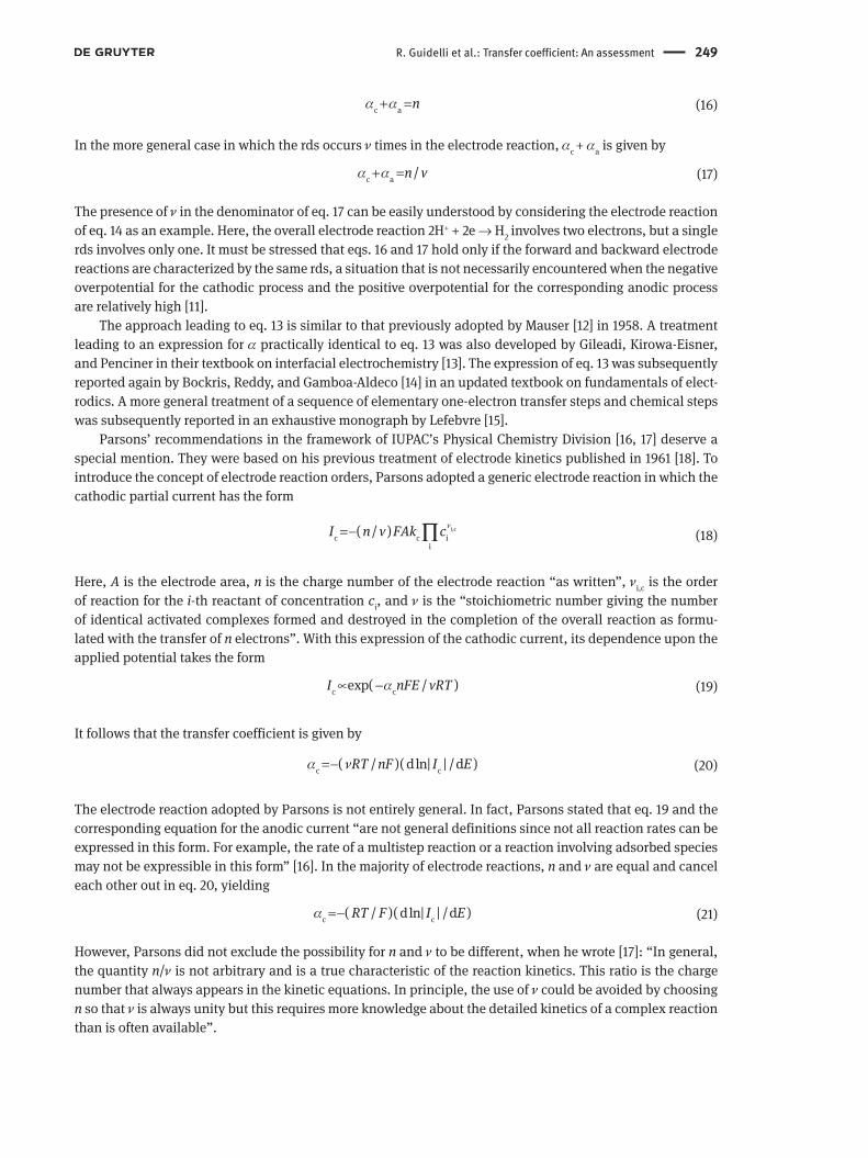
During a single one-electron cathodic reaction O + e → R, an electron must pass from an occupied energy level in the metal, close to the Fermi level, to an unoccupied energy level in the electron acceptor O, located at its position of closest approach to the electrode, in order to yield the resulting reduction product, R. To visualize schematically how this passage can occur, Fig. 3 shows a plot of the electrochemical Gibbs energy,
,G� along the reaction coordinate q for the system consisting of the reactant O plus solvent, and for the system consisting of the product R plus solvent. The minima of the two curves correspond to equilibrium configura-tions and occur at different q values because the equilibrium bond lengths of O are generally different from those of R. The parabolic curves denote deviations from the equilibrium configurations due to fluctuations of reactant translational and rotational coordinates and of orientational and atomic polarization of the sur-rounding solvent molecules. At the intersection point of the two curves, the unperturbed O and R electronic quantum states are degenerate. The interaction breaks the degeneracy, giving rise to a lower and an upper “mixed” curve (the two solid curves). The energy at the maximum of the lower solid curve is less than that at the intersection point by an electronic interaction energy ε12, called the “resonance energy” [25, 26]. The ver-tical distance between the minimum of the O curve and the maximum of the lower solid curve measures the barrier height, *,G∆ � for the electrode reaction. The vertical distance between the minima of the two curves is given by the electrochemical Gibbs energy of the electrode reaction, ( ),G G F E E∆ ∆= °+ − °� � where G∆ °� is its value at the standard potential E° and F(E – E°) is the shift from this value when an overpotential η is applied. A negative overpotential lowers the R curve vertically with respect to the O one.
Fig. 3 Electrochemical Gibbs energy, �,G along the reaction coordinate q for the system consisting of the reactant O plus solvent, and for the system consisting of the product R plus solvent. The inset shows the two extreme situations of activation-less and barrierless reactions.
R. Guidelli et al.: Transfer coefficient: An assessment 251
If η is made so negative as to cause the minimum of the O curve to intersect the R curve, as shown in the inset of Fig. 3, *G∆ � vanishes and the cathodic reaction is defined as “activationless”. Under this extreme situation, a very small increase in the negative value of η causes a slight downward shift in the R curve, which maintains the barrier height practically equal to zero. Since the current depends exponentially upon
*,G∆ � the rate of change of the current density jc with a change in η is practically zero, and the same is true for the symmetry factor β, in view of eq. 11. On the other hand, if η is made so positive as to bring the minimum of the R curve to intersect the O curve, as shown in the inset of Fig. 3, the cathodic reaction is referred to as “barrierless”. In this further extreme case, the slight downward shift of the R curve caused by a very small increase in the negative value of η determines a change in *G∆ � that is practically equal to the change in Fη. This corresponds to the maximum rate of change of ln |jc| with a change in η, and hence to β = 1. These two extreme situations illustrate nicely the following alternative and equivalent definition of the symmetry factor used by several scientists:
*/ ( )d G d Fβ ∆ η≡ � (22)
The above two situations occur only rarely. Conditions favourable to the detection of barrierless electrode processes were examined by Krishtalik [27].
Only absorption of light could cause the system to move vertically from the minimum of the O curve to the R curve along the dashed line in Fig. 3. If the electron moved so slowly as to lag behind all fluctuations during its movement, then the system could pass from the minimum of the O curve to that of the R curve fol-lowing the profile of the lower solid curve in Fig. 3. However, the electron moves so fast that all fluctuations are frozen during its movement, with the only exception of electronic and vibrational fluctuations. Hence, in order to tunnel across the potential energy barrier, the transferring electron must await the favourable situation in which the various fluctuations bring the system to the maximum of the lower solid curve. This position corresponds to a compromise non-equilibrium nuclear configuration and polarization of the solvent molecules, which is intermediate between those of O and R and causes the energy level of the electron in the reactant molecule to match that in the metal. If the resonance energy ε12 is small, the system will have a low probability to jump from the O to the R curve when passing through the intersection between the O and R curves as a consequence of fluctuations, and the reaction is termed non-adiabatic. Conversely, if this prob-ability is close to unity, the reaction is termed adiabatic.
The barrier height *G∆ � in Fig. 3 can be estimated if the resonance energy is small enough that the maximum of the lower solid curve can be approximately identified with the intersection point between the O and R curves. Assuming harmonic Gibbs energy curves and referring to the standard potential E°, we can write
o 2 o 2O O R R( ) ( ) / 2 ( ); ( ) ( ) / 2 ( )G q k q q G q k q q G b∆= − = − + °� � �a (23)
Here, qO and qR are the abscissas of the minima of the O and R curves, respectively, and k is a force constant, which is assumed equal for O and R. Incidentally, due to the change in charge taking place during the elec-trode process, the vibrational modes and interactions with the solvent can be significantly different for the O and the R species; this would lead to O ad R parabolas with different curvatures in Fig. 3 [28]. At the inter-section of the dotted curves, one has o o
O R( *) ( *),G q G q=� � which can be solved to obtain the q value, q*, at the intersection. By then substituting q* into eq. 23a and rearranging terms, we obtain the height of the Gibbs energy barrier relative to the minimum of the O curve
2o o 2O O O O R( *) ( ) * 1 with: ( )
4 2G kG q G q G q qλ ∆
∆ λλ
°− ≡ ° = + = −
�� � �
(24)
The quantity λ/4 is the height of the Gibbs energy barrier when G∆ °� equals zero; it is a measure of the reor-ganization energy provided by thermal fluctuations that is required for a one-electron transfer. In electrode reactions, λ is always < ∆ �| | .G
252 R. Guidelli et al.: Transfer coefficient: An assessment
According to the Marcus theory of charge transfer [25], for highly polar solvents such as water, λ is pro-portional to the square of the charge, Δe, which is transferred:
2( ) .K eλ ∆= (25)
This dependence is intuitive, because the work required to transfer a charge –e to a molecule of charge ze by infinitesimal charge increments dQ is given by 2 2 2
00( ) [ / 2 ] / 2.
e eze Q dQ zeQ Q ze e− −+ = + =− +∫ The fact that
the solvent reorganization energy depends quadratically upon the charge to be transferred explains why the simultaneous transfer of more than one electron in a multi-electron process is quite difficult. In a two-elec-tron process, it is much more probable that the two electrons are transferred consecutively. For the simultane-ous transfer of two electrons to take place, the time required for such a transfer must be so short as to leave thermal fluctuations completely frozen. In this “concerted” two-electron transfer, the intermediate species must have such a high energy as to be practically non-existing.
For an approximate estimate of the conditions to be satisfied for a concerted two-electron transfer to take place, we can set the reorganization energy, λ12, for such an event as equal to 4λ1 in view of eq. 25, where λ1 is the reorganization energy for the first one-electron transfer [29]:
2 2 2o o oo o1 1 12 12 121 12 1
1 12 1
* 1 ( ); * 1 1 ( )4 4 4
G G GG a G b
λ ∆ λ ∆ ∆∆ ∆ λ
λ λ λ
= + = + = +
� � �� �
(26)
Here, o12G∆ � is the standard Gibbs energy for the overall two electron transfer, while o
1G∆ � is that for the first one-electron transfer. These are related to the standard potentials o
1E and o2E for the first and second one-
electron transfer, respectively, and to that, o o o12 1 2( ) / 2,E E E= + for the overall two-electron transfer, by the
equations
o o o o o o1 1 12 12 1 2; 2 ( )G FE G FE F E E∆ ∆=− =− =− +� �
(27)
The rate constant, kc, for a cathodic process depends exponentially upon *:G∆ °�
c
*exp Gk ART
∆ °= −
�
(28)
If a two-electron process proceeds by two parallel pathways of equal rate, one with a stepwise and the other with a concerted electron transfer, then both the pre exponential factor A and the standard Gibbs energy
*G∆ °� must be the same for the two pathways. Setting o1 *G∆ � in eq. 26a equal to o
12G∆ � in eq. 26b and rear-ranging terms we obtain
o o1 1 12 / 2G G∆ λ ∆= +� �
(29)
or, in view of eq. 27
o o2 1 1( ) 2F E E λ− =
(30)
Thus, the crossing point between stepwise and concerted behaviour requires that o2E be much more positive
than o1E (very high “potential inversion”). This is tantamount to stating that the addition of the second elec-
tron must occur with much greater ease than the first. If o o2 1( )E E− is greater than 2λ/F, the intermediate in
the two-electron process is of too high an energy to be accessed, such that, in practice, the process proceeds directly without any intermediate. This condition is quite difficult to be fulfilled. It should also be noted that, in the majority of multistep cathodic (anodic) processes, the release (uptake) of one electron by the electrode is followed by a chemical step before the release (uptake) of a further electron [30]. One particular case in
R. Guidelli et al.: Transfer coefficient: An assessment 253
which some evidence for a two-electron process fulfilling the condition of eq. 30 exists is represented by the self-exchange reaction Tl3+(aq) + 2e ⇔ Tl+(aq) in acidic media [31].
3 The appropriate use of the transfer coefficient for the investiga-tion of electrode kinetics
First of all, it must be stated that the definitions of the transfer coefficient in eqs. 3 and 6 are conceptu-ally correct. However, an elementary step involving the simultaneous release or uptake of more than one electron by the electrode is regarded as highly improbable in view of the absolute rate theory of electron transfer of Marcus [26], where the energy requirements for medium reorganization associated with electron transfer are considered to favour incremental transfer of charge. Hence, these definitions are strictly valid only when they refer to an elementary one-electron transfer step, i.e., for n = 1. It should be stressed that, even regarding the simultaneous release or uptake of more than one electron as not completely improb-able, the definitions in eqs. 3 and 6 necessarily refer to a single elementary step. On the other hand, the determination of the transfer coefficient for a cathodic or anodic reaction requires the experimental meas-urement of the Tafel slope, dE/dln|j|, for such reaction, which is often a multistep process. Consequently, the applicability of eqs. 3 and 6 is confined to an electrode reaction consisting of a single elementary one-electron transfer step. Since many electrode reactions involve the participation of more than one electron, their mechanistic investigation should include different elementary one-electron transfer steps in the reac-tion scheme.
Quite probably, the erroneous mechanistic conclusions stemming from the kinetic equations contained in the first edition of Bard and Faulkner’s textbook [23], which make use of the notations of eqs. 3 and 6 and are frequently referred to in the literature, led the authors to replace αn by α in all the kinetic equations of the second edition [24]. It should be stressed that such a replacement by no means implies that the resulting α value refers exclusively to an electrode process consisting of a single one-electron transfer step. In fact, many boundary value problems rely on a boundary condition of the form kc = k0exp[–αcF(E – E°)/RT] or jc ∝ cO k0exp[–αcF(E – E°)/RT], according to which the plot of the logarithm of kc or of the current density jc, as referred to the reactant concentration cO at the electrode surface, varies linearly with the applied potential. Consequently, the transfer coefficient α obtained from the kinetic equations resulting from the solution of the above boundary value problems is nothing else but the reciprocal of the Tafel slope multiplied by (RT/F), and may well assume values different from those relative to a one-electron transfer step.
In the frequent case in which a multistep electrode reaction consists of a sequence of elementary one-electron transfer steps and chemical steps, the transfer coefficient can be estimated by the quasi-equilibrium method, which assumes that all the steps are in equilibrium, with only the exception of the rds. In general, this assumption requires that the rate constant of the rds be at least 100 times smaller than those of all steps that precede the rds. Under these conditions, the Nernst equation is applied to one-electron transfer steps in quasi-equilibrium, while the law of mass action is applied to chemical steps in quasi-equilibrium. Alter-natively, the steady-state method can be adopted. According to this method, after a short induction period after initiation of the process, the effective concentrations of all intermediates are assumed to reach values that remain constant in time and, therefore, are in a steady state; this implies that the rates of their forma-tion and disappearance will be equal, with the result that the rates of change of their concentrations will be zero. Usually, this approach yields more complicated expressions for the transfer coefficient, which may be simplified only upon making assumptions about the relative magnitudes of some of the rate constants, thus neglecting some terms. An exhaustive treatment of the transfer coefficient for multistep electrode reactions, including adsorption of intermediates and combination or dissociation rate-determining steps, can be found in Lefebvre’s monograph [15]. Even in the absence of reactant adsorption, the mechanistic interpretation of an electrode process becomes quite complicated if the formal potentials of two consecutive one-electron transfer steps are very close [32].
254 R. Guidelli et al.: Transfer coefficient: An assessment
A detailed treatment covering the application of quasi-equilibrium and steady-state approaches to the determination of the transfer coefficient for different electrode reaction schemes is outside the scope of this report. Here, we will confine ourselves to exemplifying a multistep electrode reaction by examining a simple sequence of two one-electron transfer steps and two protonation steps according to the quasi-equilibrium method:
o1 1
2 2
o3 3
4 4
;
;
;
;2
O e R ( )R H RH ( )
RH e RH ( )RH H RH ( )
k E
k K
k E
k K
ab
cd
−
− +
−
− +
+ →
+ →
+ →
+ →
(31)
Here, k1, k2, k3, k4 are forward rate constants, o o1 3, E E are formal potentials for the one-electron transfer steps
31a and 31c, and K2, K4 are equilibrium constants for the protonation steps 31b and 31d; the rate constants k2 and k4 of the two one-electron transfer steps can be expressed in m3‧mol–1‧s–1 units, whereas the rate constants k2 and k4 of the two protonation steps can be expressed in m6‧mol–2‧s–1 units.
Let us first assume that step 31a is the rds. In this case, the current Ic is given by
o
1 12 [ O] exp[ ( )] with:cFI FAk f E E f
RTβ=− − − ≡
(32)
A is the electrode area, E is the applied potential, and [O] is the concentration of O. Moreover, the symmetry factor β is the transfer coefficient for a one-electron transfer step; in the case of a symmetric potential energy barrier, β equals 0.5. In view of eq. 32, in the present case the transfer coefficient is given by β.
If step 31b is the rds, then the current Ic is given by
22 [ R ][ H ]cI FAk − +=− (33)
By applying to step 31a the quasi-equilibrium conditions, namely, the Nernst equation, we obtain
o1[ O] / [ R ] exp[ ( )]f E E− = −
(34)
Upon replacing [R–] from eq. 34 into eq. 33 we have
o
c 2 12 [ H ][ O] exp[ ( )]I FAk f E E+=− − − (35)
In this case, the slope of a plot of ln|Ic| against E at constant reactant concentration [O] provides a transfer coefficient αc equal to unity.
If step 31c is the rds, the current is given by
o oc 3 3 3 1 3 1
o o1 3 1 3
2 [ RH ] exp[ ( )] 2 [ RH ] exp[ ( )]with: exp[ ( )]I FAk f E E FAk K f E E
K f E Eβ β
β→
→
=− − − =− − −≡ − −
(36)
By applying to step 31b the quasi-equilibrium conditions, we obtain
2[ RH ] / [ R ][ H ] K− + = (37)
Upon replacing [RH] from eq. 37 into eq. 36 and [R–] from eq. 34 into the resulting equation, we have
o
3 1 3 2 12 [ H ][ O] exp[ ( 1 ) ( )]cI FAk K K f E Eβ+→=− − + −
(38)
R. Guidelli et al.: Transfer coefficient: An assessment 255
In this case, the slope of a plot of ln|Ic| against E at constant [O] provides a transfer coefficient αc equal to (1 + β).
Finally, if step 31d is the rds, the current Ic is given by
42 [ RH ][ H ]cI FAk − +=− (39)
Upon applying the quasi-equilibrium conditions to the electron transfer step 31c, we have
o ' o3 1 3 1
' o o1 3 1 3
[ RH ] / [ RH ] exp[ ( )] exp[ ( )]with: exp[ ( )]
f E E K f E EK f E E
−→
→
= − − = − −≡ − −
(40)
Upon replacing [RH–] from eq. 40 into eq. 39, and then [RH] from eq. 37 and [R–] from eq. 34 into the resulting equation, we obtain
' 2 o
4 1 3 2 12 [ H ] [ O] exp[ 2 ( )]cI FAk K K f E E+→=− − −
(41)
In this case, the slope of a plot of ln|Ic| against E at constant [O] yields a αc value of 2.These results can be readily generalized by stating that, in a multistep cathodic reaction consisting of a
sequence of elementary steps with only one rds, the transfer coefficient is given by eq. 13. If the rds does not involve electrons, nr equals zero and the rds is a chemical step. Conversely, if nr is different from zero, it has a very high probability of being equal to unity.
The meaning of the symmetry factor β has been interpreted on the basis of different models, none of which has met with a general consensus. Butler [1] considered β to represent the fraction of the potential-distance profile across the electrical double layer (with the exclusion of the diffuse layer) that enhances the electron transfer rate by bringing the reactant on top of the potential-energy barrier, where the transition-state complex is located. If the potential energy barrier is symmetric and symmetrically located within the electrical double layer, then β equals 0.5. Hush [33] considered β to be the fractional charge on the reacting ion in the transition state. Marcus regarded β as a multicomponent term that depends upon the reorganiza-tion of the medium necessary to attain the transition state and is a function of the applied overpotential [34, 35]. If the force constants for the reactant O and the product R are equal, as in eq. 23, Marcus theory predicts a β value very close to 0.5 for high values of the solvent reorganization energy λ [36]. However, if the two force constants are different, according to the asymmetric Marcus theory, then large deviations of β from 0.5 can be predicted [28].
Large deviations of β from the 0.5 value are also expected if the reactant exchanges an electron with the metal while being in the adsorbed state. In fact, in the absence of specific adsorption, the potential-distance profile is regarded as linear between the metal surface plane and the locus of the centre of charge of hydrated ions in their position of closest approach to the electrode, i.e., the outer Helmholtz plane (OHP). The distance between the electrode surface plane and the OHP, namely, the thickness of the electrochemical double layer, is approximately given by the diameter of a water molecule plus the radius of the hydrated ions. Specifi-cally adsorbed ions bring their centre of charge to a closer distance from the electrode surface plane, on the so-called inner Helmholtz plane (IHP). Specifically adsorbed reactant molecules, no matter if charged or neutral, are also located in the proximity of the IHP. Hence, the potential distance profile across which the electron is transferred is that between the electrode surface plane and the IHP. Therefore, the fraction β of the potential distance profile across the whole electrochemical double layer that enhances the electron-transfer rate is smaller than that in the absence of reactant adsorption. It should be noted that the above significance of the symmetry factor β cannot be attached to processes of metal deposition and dissolution, in which the charge is carried across the electrified interface by metal ions, and not by electrons [36]. The same consid-erations apply to all electrode processes in which both mass and charge are transferred across the interface, such as corrosion. In conclusion, the use of the transfer coefficient, with β ≈ 0.5, for the elucidation of the mechanism of electrode reactions has some limitations and should always be made cum grano salis.
256 R. Guidelli et al.: Transfer coefficient: An assessment
4 The misuse of the expressions of the transfer coefficient in eqs. 3 and 6
The direct way to measure the transfer coefficient consists in plotting the natural logarithm of the current I, corrected for any change in the reactant concentration at the electrode surface with respect to its bulk value, against the applied potential E, and in multiplying its slope by –RT/F for a cathodic reaction or by RT/F for an anodic one. Denoting the resulting “cathodic quantity” by αcn (with αc the cathodic transfer coefficient) or the resulting “anodic quantity” by αan (with αa the anodic transfer coefficient) may generate unwarranted mechanistic interpretations.
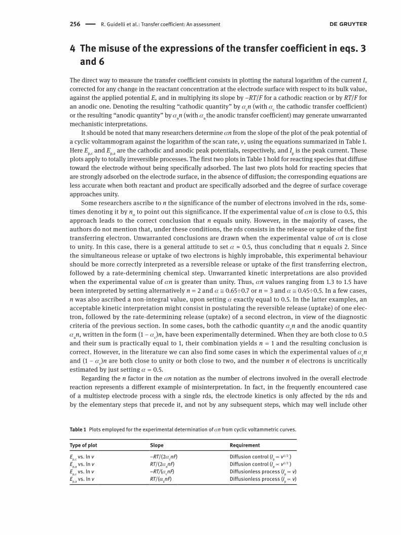
It should be noted that many researchers determine αn from the slope of the plot of the peak potential of a cyclic voltammogram against the logarithm of the scan rate, v, using the equations summarized in Table 1.Here Ep,c and Ep,a are the cathodic and anodic peak potentials, respectively, and Ip is the peak current. These plots apply to totally irreversible processes. The first two plots in Table 1 hold for reacting species that diffuse toward the electrode without being specifically adsorbed. The last two plots hold for reacting species that are strongly adsorbed on the electrode surface, in the absence of diffusion; the corresponding equations are less accurate when both reactant and product are specifically adsorbed and the degree of surface coverage approaches unity.
Some researchers ascribe to n the significance of the number of electrons involved in the rds, some-times denoting it by nα to point out this significance. If the experimental value of αn is close to 0.5, this approach leads to the correct conclusion that n equals unity. However, in the majority of cases, the authors do not mention that, under these conditions, the rds consists in the release or uptake of the first transferring electron. Unwarranted conclusions are drawn when the experimental value of αn is close to unity. In this case, there is a general attitude to set α ≈ 0.5, thus concluding that n equals 2. Since the simultaneous release or uptake of two electrons is highly improbable, this experimental behaviour should be more correctly interpreted as a reversible release or uptake of the first transferring electron, followed by a rate-determining chemical step. Unwarranted kinetic interpretations are also provided when the experimental value of αn is greater than unity. Thus, αn values ranging from 1.3 to 1.5 have been interpreted by setting alternatively n = 2 and α ≅ 0.65÷0.7 or n = 3 and α ≅ 0.45÷0.5. In a few cases, n was also ascribed a non-integral value, upon setting α exactly equal to 0.5. In the latter examples, an acceptable kinetic interpretation might consist in postulating the reversible release (uptake) of one elec-tron, followed by the rate-determining release (uptake) of a second electron, in view of the diagnostic criteria of the previous section. In some cases, both the cathodic quantity αcn and the anodic quantity αan, written in the form (1 – αc)n, have been experimentally determined. When they are both close to 0.5 and their sum is practically equal to 1, their combination yields n = 1 and the resulting conclusion is correct. However, in the literature we can also find some cases in which the experimental values of αcn and (1 – αc)n are both close to unity or both close to two, and the number n of electrons is uncritically estimated by just setting α = 0.5.
Regarding the n factor in the αn notation as the number of electrons involved in the overall electrode reaction represents a different example of misinterpretation. In fact, in the frequently encountered case of a multistep electrode process with a single rds, the electrode kinetics is only affected by the rds and by the elementary steps that precede it, and not by any subsequent steps, which may well include other
Table 1 Plots employed for the experimental determination of αn from cyclic voltammetric curves.
Type of plot Slope Requirement
Ep,c vs. ln v –RT/(2αcnF) Diffusion control (Ip ∝ v1/2 )Ep,a vs. ln v RT/(2αanF) Diffusion control (Ip ∝ v1/2 )Ep,c vs. ln v –RT/(αcnF) Diffusionless process (Ip ∝ v)Ep,a vs. ln v RT/(αanF) Diffusionless process (Ip ∝ v)
R. Guidelli et al.: Transfer coefficient: An assessment 257
electron-transfer steps. In this case, n values have often been determined by independent means, e.g., by exhaustive electrolysis or from the charge involved in the complete electroreduction or electrooxidation of a specifically adsorbed reactant. The resulting n values were then used to extract α from the experimental value of αn. This erroneous procedure often leads to improbably low α values of the order of 0.1.
5 ConclusionsEquations 3 and 6, albeit formally correct, are often misused in electrode kinetics, generating unwarranted mechanistic conclusions. The appropriate way to eliminate the possibility of misleading interpretations of these equations consists of proposing the following definitions for the cathodic transfer coefficient αc and for the anodic one, αa:
c c a a( / )( dln| | /d ); ( / )( dln / d )RT F j E RT F j Eα α=− = (42)
This simply requires the removal of the factor n from the denominator of eqs. 3 and 6. The definitions of eq. 42 are each based on a directly determined experimental quantity, independent of any possible mecha-nistic conclusion. The numerical value of the transfer coefficient α can by no means be assumed; it can only be obtained by measuring the Tafel slope dE/dln|j|. It should be stressed that determining the reaction mechanism remains a quite demanding task, but the definition of the transfer coefficient as proposed herein prevents an unjustified a priori assumption on the n value from invalidating the mechanism from the very beginning.
For an electrode process with the same rds in the cathodic and anodic directions, we have
c a /n vα α+ = (43)
where n is the total number of electrons involved and ν is the number of occurrences of the rds in the electrode reaction, as written. The use of the cathodic symmetry factor, βc, and the anodic one, βa, should be confined to an overall electrode reaction consisting exclusively of a one-electron transfer step or, more generally, to a single one-electron transfer step participating in a multistep electrode process; in the latter case, βc and βa are no longer directly measurable experimental quantities and rely on a mechanistic interpretation of the electrode process. In both cases we have
c a 1β β+ =
The definition of the transfer coefficient in eq. 42 is the subject of the IUPAC Recommendation 2014 that immediately follows this technical report [37].
Membership of sponsoring bodyMembership of the IUPAC Physical and Biophysical Chemistry Division Committee for the period 2012–2013 was as follows:
President: K. Yamanouchi (Japan); Vice President: R. Marquardt (France); Secretary: A. Wilson (USA); Past President: A. McQuillan (New Zealand); Titular Members: K. Bartik (Belgium); A. Friedler (Israel); A. Goodwin (USA); R. Guidelli (Italy); A. Russell (UK); J. Stohner (Switzerland); Associate Members: V. Barone (Italy); A. Császár (Hungary); V. Kukushkin (Russia); V. Mišković-Stanković (Serbia); Á. Mombrú Rodríguez (Uruguay); X. S. Zhao (China); National Representatives: K. Bhattacharyya (India); J. Cejka (Czech Republic); S. Hannongbua (Thailand); M. Koper (Netherlands); A. J. Mahmood (Bangladesh); O. Mamchenko (Ukraine); J. Mdoe (Tanzania); F. Quina (Brazil); N. Soon (Malaysia); V. Tomišić (Croatia).
258 R. Guidelli et al.: Transfer coefficient: An assessment
References[1] (a) J. A. V. Butler. Trans. Faraday Soc. 19, 729 (1924); (b) J. A. V. Butler. Trans. Faraday Soc. 19, 734 (1924).[2] T. Erdey-Gruz, M. Volmer. Z. Physik. Chem. A 150, 203 (1930).[3] P. Delahay. New Instrumental Methods in Electrochemistry, pp. 32–36, Interscience, New York (1954).[4] P. Delahay. Double Later and Electrode Kinetics, pp. 178–180, Interscience, New York (1965).[5] B. E. Conway. Theory and Principles of Electrode Processes, pp. 109–117, Ronald Press, New York (1965).[6] B. E. Conway, M. Salomon. Electrochim. Acta 9, 1599 (1964).[7] K. J. Vetter. Electrochemical Kinetics. Theoretical and Experimental Aspects, pp. 149–154, Academic Press, New York (1967);
translated from Electrochemische Kinetik, Springer Verlag, Berlin (1961).[8] J. P. Brenet, K. Troare. Transfer Coefficients in Electrochemical Kinetics, Academic Press, London (1971).[9] T. Erdey-Gruz. Kinetics of Electrode Processes, pp. 56–59, Adam Hilger, London (1972).
[10] J. O’M. Bockris, A. K. N. Reddy. Modern Electrochemistry, Vol. 2, pp. 997–1002, Plenum, New York (1970).[11] R. M. Hurd. J. Electrochem. Soc. 109, 327 (1962).[12] H. Mauser. Z. Elektrochem. Ber. Bunsenges. Physik. Chem. 62, 419 (1958).[13] E. Gileadi, E. Kirowa-Eisner, J. Penciner. Interfacial Electrochemistry, An Experimental Approach, pp. 52–55, Addison-Wesley,
Reading, MA (1975).[14] J. O’M. Bockris, A. K. N. Reddy, M. Gamboa-Aldeco. Modern Electrochemistry 2A: Fundamentals of Electrodics, pp. 1182–1187,
Kluwer/Plenum, New York (2000).[15] M. Lefebvre. In Modern Aspects of Electrochemistry, Vol. 32, B. E. Conway, J. O’M. Bockris, R. E. White (Eds.), pp. 249–300,
Kluwer Academic/Plenum, New York (2002).[16] R. Parsons. IUPAC Manual of Symbols and Terminology for Physicochemical Quantities and Units. Appendix III. Electro-
chemical Nomenclature, pp. 500–516, Butterworths, London (1973).[17] R. Parsons. Pure Appl. Chem. 52, 233 (1979).[18] R. Parsons. In Advances in Electrochemistry and Electrochemical Engineering, Vol. 1, P. Delahay (Ed.), pp. 1–64, Intersci-
ence, New York (1961).[19] IUPAC. Quantities, Units and Symbols in Physical Chemistry, 3rd ed. (the “Green Book”). Prepared for publication by E. R.
Cohen, T. Cvitaš, J. G. Frey, B. Holmström, K. Kuchitsu, R. Marquardt, I. Mills, F. Pavese, M. Quack, J. Stohner, H. L. Strauss, M. Takami, A. J. Thor, RSC Publishing, Cambridge, UK (2007).
[20] R. Greef, P. Peat, L. M. Peter, D. Pletcher, J. Robinson. Instrumental Methods in Electrochemistry, pp. 22–26, Ellis Horwood, Chichester (1985).
[21] J. Goodisman. Electrochemistry: Theoretical Foundations, pp. 35–43, John Wiley, New York (1987).[22] C. M. A. Brett, A. M. Oliveira Brett. Electrochemistry: Principles, Methods, and Applications, pp. 72–76, Oxford University
Press (1993).[23] A. J. Bard, L. R. Faulkner. Electrochemical Methods: Fundamentals and Applications, 1st ed., John Wiley, New York (1980).[24] A. J. Bard, L. R. Faulkner. Electrochemical Methods: Fundamentals and Applications, 2nd ed., John Wiley, New York (2001).[25] R. A. Marcus. In Special Topics in Electrochemistry, A. Rock (Ed.), pp. 161–209, Elsevier Scientific, Amsterdam (1977).[26] (a) R. A. Marcus. J. Chem. Phys. 24, 966 (1956); (b) R. A. Marcus. J. Chem. Phys. 26, 867 (1957); (c) R. A. Marcus. J. Chem.
Phys. 26, 872 (1957).[27] L. I. Krishtalik. J. Electroanal Chem. 21, 421 (1969).[28] E. Laborda, M. C. Henstridge, R. G. Compton. J. Electroanal. Chem. 667, 48 (2012).[29] E. Gileadi. J. Electroanal. Chem. 532, 181 (2002).[30] D. H. Evans. Chem. Rev. 108, 2113 (2008).[31] L. D. Zusman, D. N. Beratan. J. Phys. Chem. A 101, 4136 (1997).[32] A. Batchelor-McAuley, R. G. Compton. J. Electroanal. Chem. 669, 73 (2012).[33] N. S. Hush. J. Chem. Phys. 28, 962 (1958).[34] R. A. Marcus. Can. J. Chem. 37, 155 (1959).[35] R. A. Marcus. Biochim. Biophys. Acta 811, 265 (1985).[36] E. Gileadi. J. Electroanal. Chem. 660, 247 (2011).[37] R. Guidelli, R. G. Compton, J. M. Feliu, E. Gileadi, J. Lipkowski, W. Schmickler, S. Trasatti. Pure Appl. Chem. 86, 259 (2014).
Note: Republication or reproduction of this report or its storage and/or dissemination by electronic means is permitted without the need for formal IUPAC or De Gruyter permission on condition that an acknowledgment, with full reference to the source, along with use of the copyright symbol ©, the name IUPAC, the name De Gruyter, and the year of publication, are prominently visible. Publica-tion of a translation into another language is subject to the additional condition of prior approval from the relevant IUPAC National Adhering Organization and De Gruyter.


![W -RIGIDITY FOR THE VON NEUMANN ALGEBRAS OF …arXiv:1508.04678v1 [math.OA] 19 Aug 2015 W∗-RIGIDITY FOR THE VON NEUMANN ALGEBRAS OF PRODUCTS OF HYPERBOLIC GROUPS IONUT CHIFAN, ROLANDO](https://static.fdocument.org/doc/165x107/5e7c706ad134df2adf54aa06/w-rigidity-for-the-von-neumann-algebras-of-arxiv150804678v1-mathoa-19-aug.jpg)