REMOTE CONTROL FOR CHILLER - GALLETTIord.galletti.com/imagesdb/famiglie/pdf/rg66006100.pdfThe remote...
32
REMOTE CONTROL FOR CHILLER MYCHILLER
-
Upload
phamnguyet -
Category
Documents
-
view
215 -
download
0
Transcript of REMOTE CONTROL FOR CHILLER - GALLETTIord.galletti.com/imagesdb/famiglie/pdf/rg66006100.pdfThe remote...

REMOTE CONTROL
FOR CHILLER MYCHILLER
RG66006100-Rev.01 2
GENERAL FEATURES .................................................................................................................................................. 3
MAIN FUNCTIONS AND EQUIPMENT: ................................................................................................................................ 3
LCD DISPLAY ................................................................................................................................................................. 4
KEYBOARD ..................................................................................................................................................................... 5
BOARD CONFIGURATION .......................................................................................................................................... 7
LIST OF MAIN PARAMETERS ............................................................................................................................................. 7 CONFIGURATION OF MAIN PARAMETERS.......................................................................................................................... 8
CONFIGURATION OF UNIT ........................................................................................................................................ 9
LIST OF UNIT PARAMETERS ............................................................................................................................................. 9 CONFIGURATION OF UNIT PARAMETERS .......................................................................................................................... 9
UNIT READINGS DISPLAY ........................................................................................................................................ 11
READINGS LIST ............................................................................................................................................................. 11 READING DISPLAY PROCEDURE ..................................................................................................................................... 11
SETPOINT CHANGE .................................................................................................................................................... 12
TIME BAND CONFIGURATION ................................................................................................................................ 13
(ONLY PLUS VERSION) .............................................................................................................................................. 13
GENERAL OPERATION .................................................................................................................................................... 13 PROCEDURE FOR ACCESSING TIME BAND PARAMETERS ................................................................................................. 14 PARAMETER LIST .......................................................................................................................................................... 15 PARAMETERS DEFAULT VALUES .................................................................................................................................... 17 DISPLAY OF ACTUAL TIME ............................................................................................................................................. 17
N.B. FOR REMOTE CONTROL OF UNITS PROVIDED WITH A PCO PROCESSOR WITH THE CLOCK BOARD INSTALLED, MANAGEMENT OF THE TIME BANDS IS ALSO IMPLEMENTED ON THE BOARD SOFTWARE. IF YOU WISH TO MANAGE THE TIME BAND WITH THE REMOTE CONTROL, THIS FEATURE MUST NOT BE ENABLED AT THE SAME TIME ON THE PCO BOARD. .......................... 17
UNIT ALARMS DISPLAY ........................................................................................................................................... 18
COMMUNICATION ERROR ............................................................................................................................................... 18 ALARM CODES ............................................................................................................................................................... 19
N.B. FOR A DETAILED DESCRIPTION OF THE ALARMS, CONSULT THE ELECTRONIC CONTROLLER MANUAL. SERIAL COMMUNICATION ..................................................................................... 20
CONNECTION TO RS485 COMMUNICATION NETWORK ................................................................................................... 21
MODBUS ® ...................................................................................................................................................................... 22
LIST OF PCO1/PCOXS SUPERVISION PARAMETERS ......................................................................................... 22 (MCE TANDEM / MPE TANDEM / MTE / LCE) ....................................................................................................... 26
CIRCUIT BOARD ......................................................................................................................................................... 27
WALL INSTALLATION OF CONTROL ................................................................................................................... 28
TECHNICAL DATA ...................................................................................................................................................... 30
RG66006100-Rev.01 3
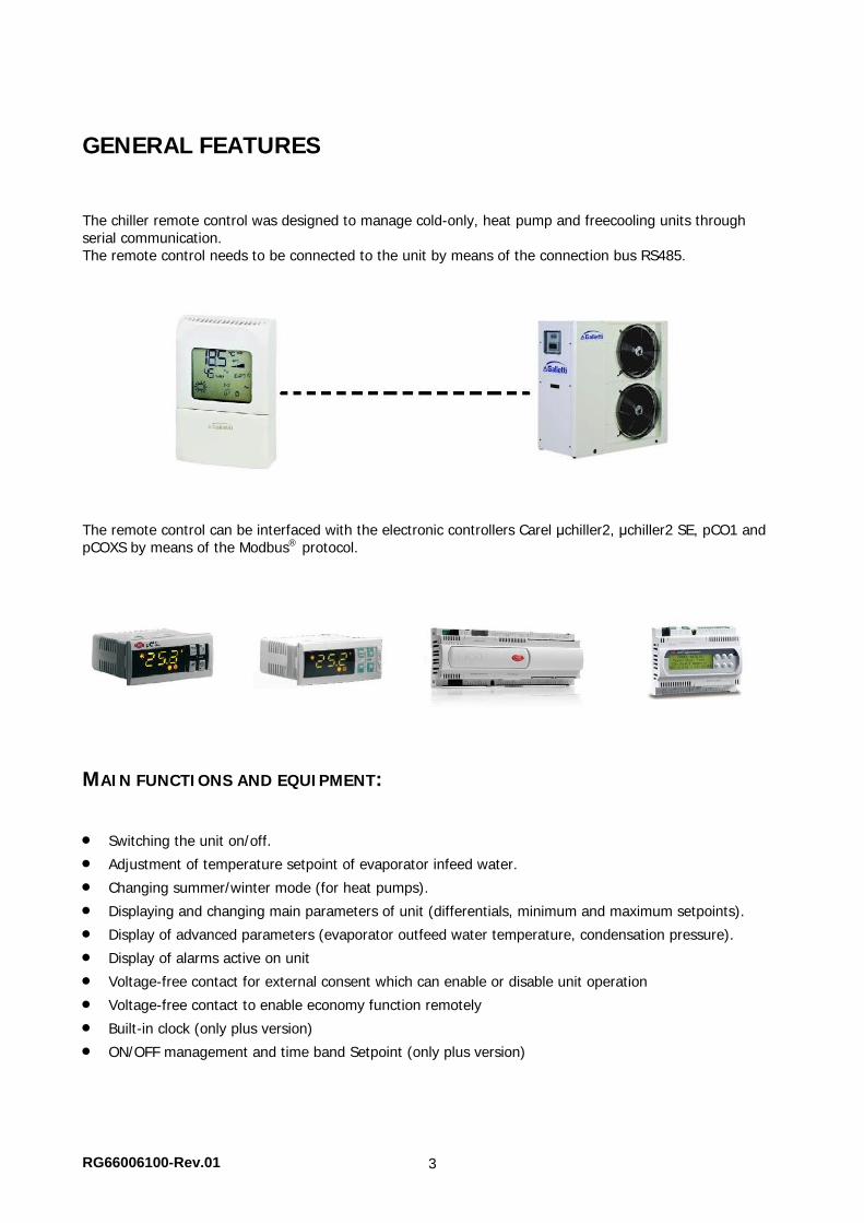
GENERAL FEATURES The chiller remote control was designed to manage cold-only, heat pump and freecooling units through serial communication. The remote control needs to be connected to the unit by means of the connection bus RS485.
The remote control can be interfaced with the electronic controllers Carel μchiller2, μchiller2 SE, pCO1 and pCOXS by means of the Modbus® protocol.
MAIN FUNCTIONS AND EQUIPMENT:
Switching the unit on/off.
Adjustment of temperature setpoint of evaporator infeed water.
Changing summer/winter mode (for heat pumps).
Displaying and changing main parameters of unit (differentials, minimum and maximum setpoints).
Display of advanced parameters (evaporator outfeed water temperature, condensation pressure).
Display of alarms active on unit
Voltage-free contact for external consent which can enable or disable unit operation
Voltage-free contact to enable economy function remotely
Built-in clock (only plus version)
ON/OFF management and time band Setpoint (only plus version)
RG66006100-Rev.01 4
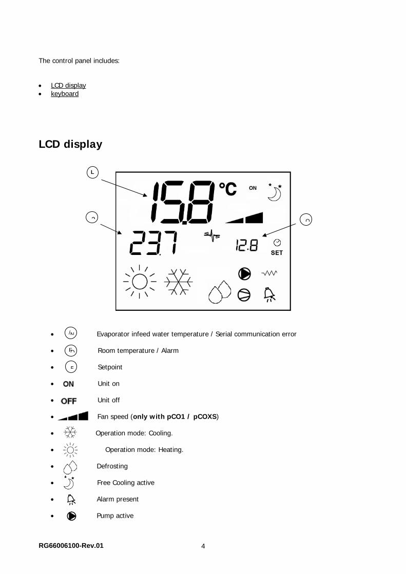
The control panel includes: LCD display keyboard
LCD display
Evaporator infeed water temperature / Serial communication error
Room temperature / Alarm
Setpoint
Unit on
Unit off
Fan speed (only with pCO1 / pCOXS)
Operation mode: Cooling. Operation mode: Heating. Defrosting
Free Cooling active
Alarm present
Pump active
3
L
O
/ N
F O
F
RG66006100-Rev.01 5
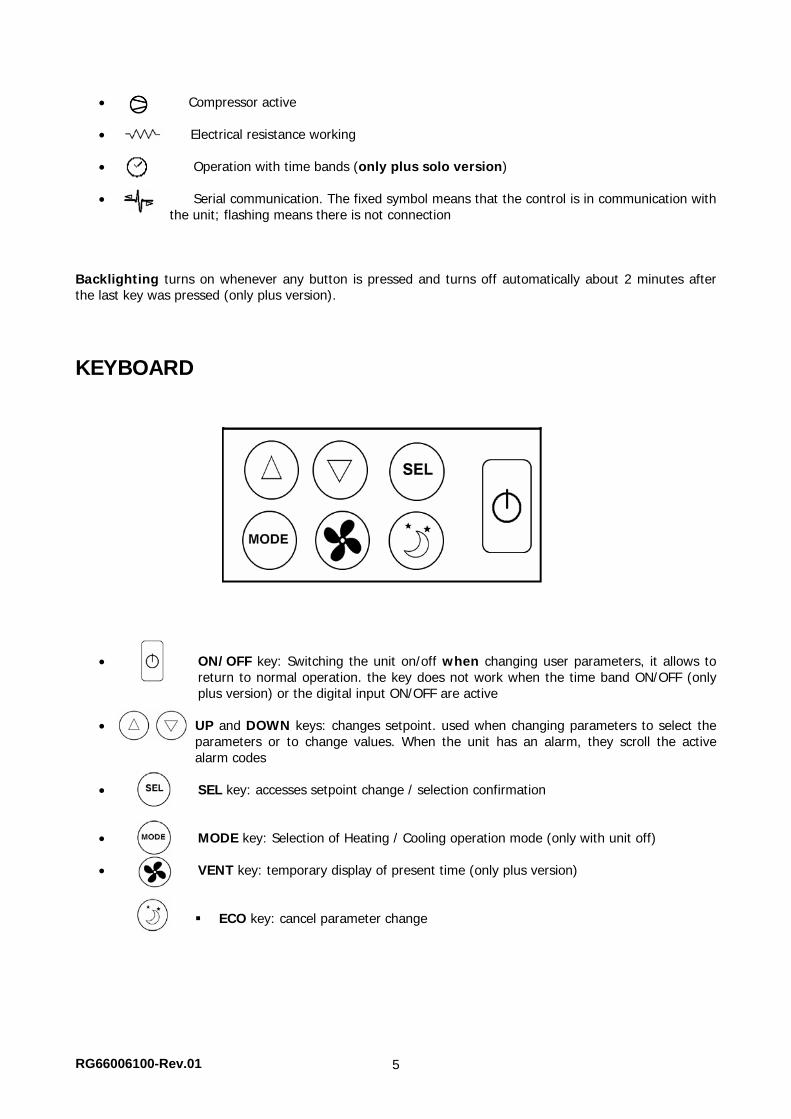
Compressor active
Electrical resistance working
Operation with time bands (only plus solo version)
Serial communication. The fixed symbol means that the control is in communication with the unit; flashing means there is not connection
Backlighting turns on whenever any button is pressed and turns off automatically about 2 minutes after the last key was pressed (only plus version).
KEYBOARD
ON/OFF key: Switching the unit on/off when changing user parameters, it allows to return to normal operation. the key does not work when the time band ON/OFF (only plus version) or the digital input ON/OFF are active
UP and DOWN keys: changes setpoint. used when changing parameters to select the
parameters or to change values. When the unit has an alarm, they scroll the active alarm codes
SEL key: accesses setpoint change / selection confirmation MODE key: Selection of Heating / Cooling operation mode (only with unit off)
VENT key: temporary display of present time (only plus version)
ECO key: cancel parameter change
RG66006100-Rev.01 6
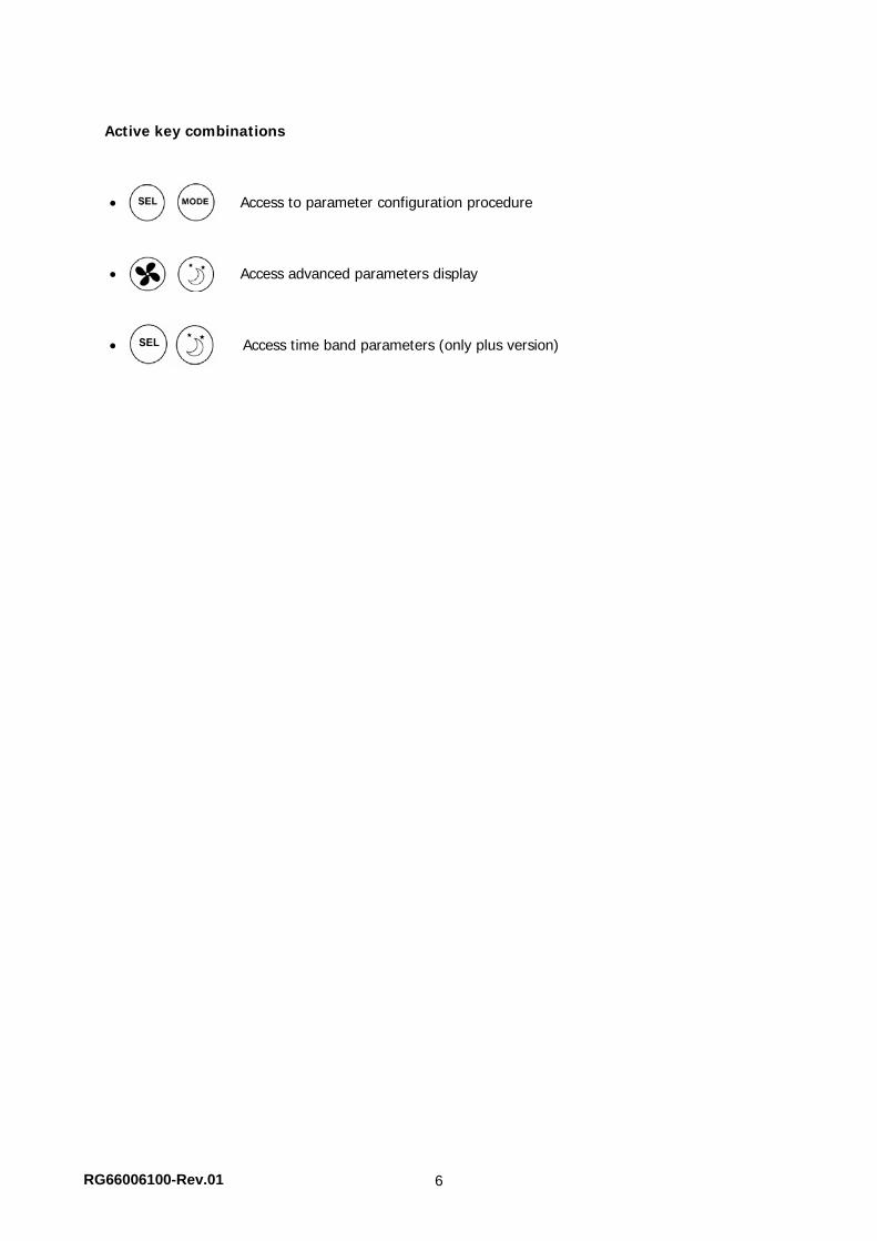
Active key combinations Access to parameter configuration procedure
Access advanced parameters display
Access time band parameters (only plus version)
RG66006100-Rev.01 7
BOARD CONFIGURATION
LIST OF MAIN PARAMETERS
SERIAL ADDRESS: sets Modbus address (between 1 and 247) of controlled unit
TYPE OF PROCESSOR: selects the type of controller present on the unit
0: μchiller2 1: μchiller2 SE 2: pCO1/pCO XS 3: μchiller2 (for MPE and MCE tandem units, MTE, LCE chiller) 4: μchiller2 (for MPE and MCE tandem units, MTE, LCE heat pump) 5: μchiller2 SE (for MPE tandem, MCE tandem, MTE, LCE chillers) 6: μchiller2 SE (for MPE tandem, MCE tandem, MTE, LCE heat pumps)
TYPE OF UNIT:
0: Chiller 1: Heat Pump
NUMBER OF CIRCUITS: sets the number of chiller circuits of the unit (1 or 2)
DIGITAL INPUT CONFIGURATION: configuration of DIN 1/2
0: DIN1 = - DIN2 = - 1: DIN1 = On/Off DIN2 = - 2: DIN1 = - DIN2 = Eco 3: DIN1 = On/Off DIN2 = Eco
If the digital input is not active, time band or keyboard switching on/off would have no effect. If the digital input Economy function is active, the set temperature will be changed to the minimum limit (for heating) or the maximum limit (for cooling). Both can be changed by the unit parameter menu of the remote control (only for models provided with μchiller 2 or μchiller 2 SE), or else directly on the controlled unit.
DIN1 LOGIC: 0: [open/closed] = [Off/On] 1: [open/closed] = [On/Off]
DIN2 LOGIC: 0: [open/closed] = [-/ECO] 1: [open/closed] = [ECO/-]
RG66006100-Rev.01 8
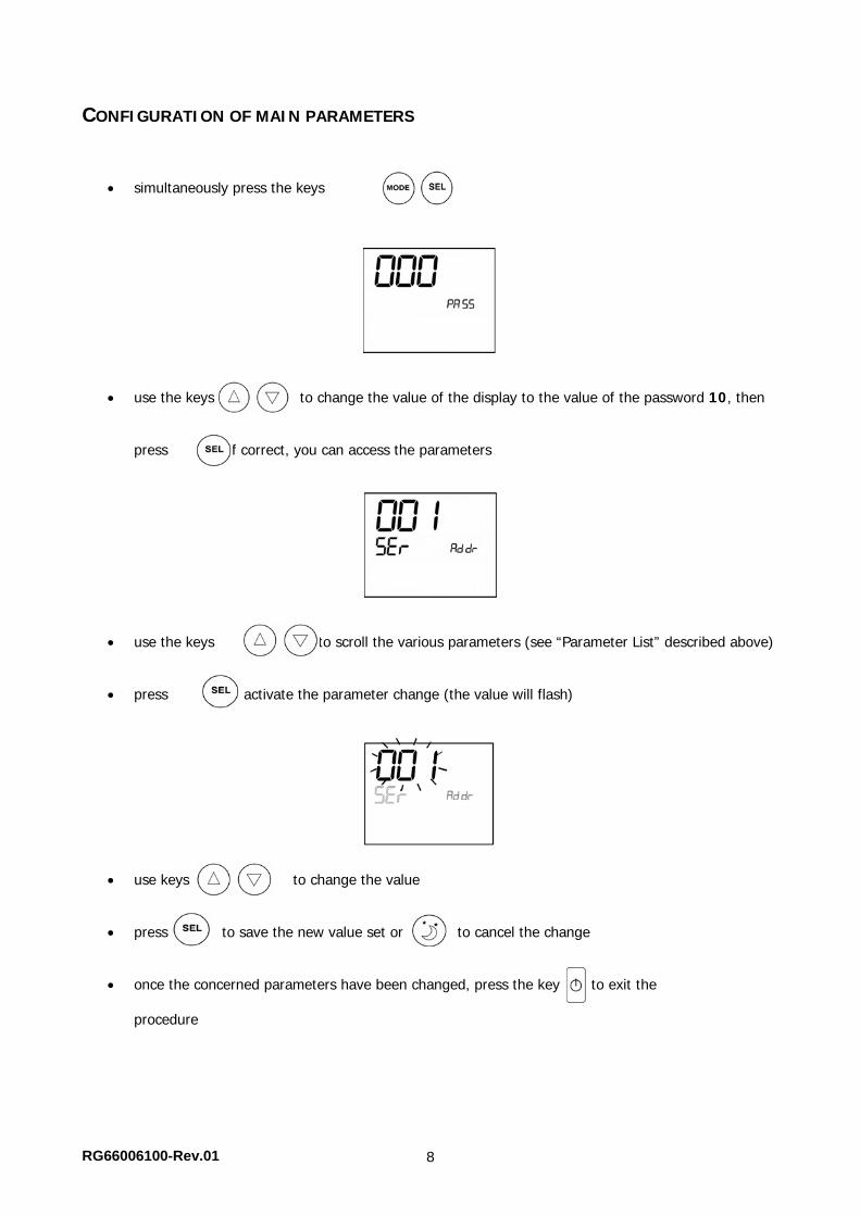
CONFIGURATION OF MAIN PARAMETERS
simultaneously press the keys
use the keys to change the value of the display to the value of the password 10, then
press . If correct, you can access the parameters
use the keys to scroll the various parameters (see “Parameter List” described above)
press to activate the parameter change (the value will flash)
use keys to change the value
press to save the new value set or to cancel the change
once the concerned parameters have been changed, press the key to exit the procedure
RG66006100-Rev.01 9
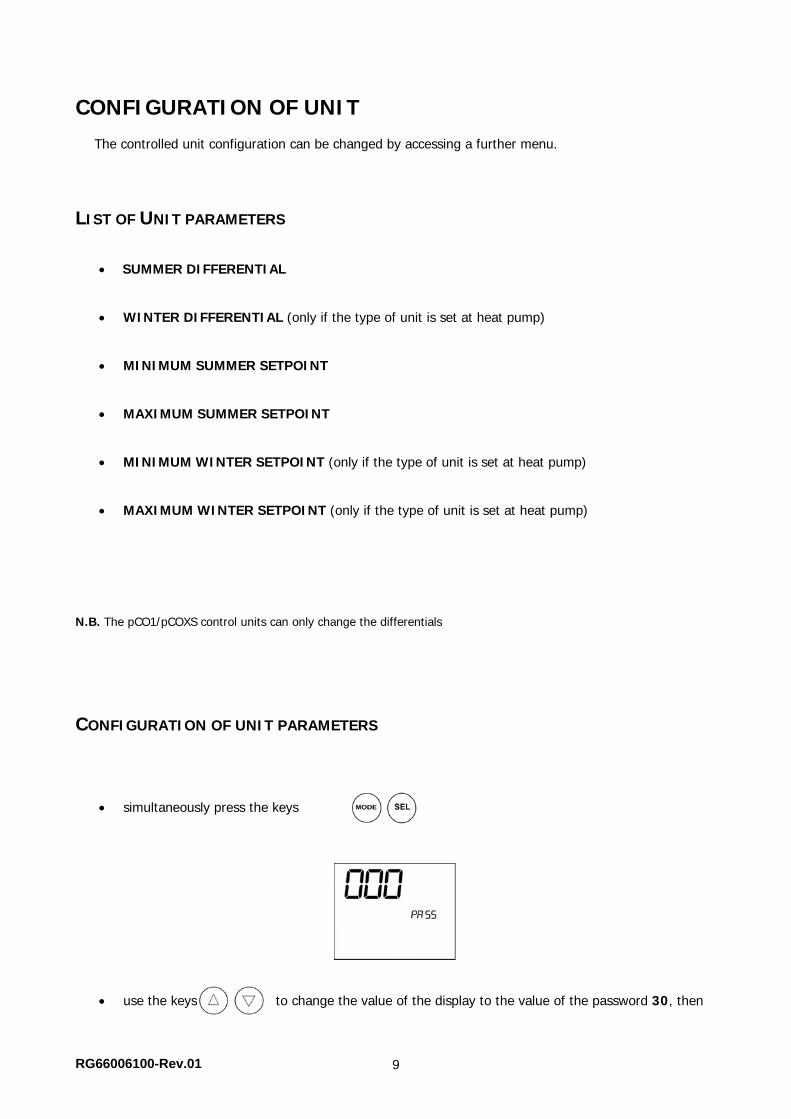
CONFIGURATION OF UNIT
The controlled unit configuration can be changed by accessing a further menu.
LIST OF UNIT PARAMETERS
SUMMER DIFFERENTIAL
WINTER DIFFERENTIAL (only if the type of unit is set at heat pump)
MINIMUM SUMMER SETPOINT
MAXIMUM SUMMER SETPOINT
MINIMUM WINTER SETPOINT (only if the type of unit is set at heat pump)
MAXIMUM WINTER SETPOINT (only if the type of unit is set at heat pump) N.B. The pCO1/pCOXS control units can only change the differentials
CONFIGURATION OF UNIT PARAMETERS
simultaneously press the keys
use the keys to change the value of the display to the value of the password 30, then
RG66006100-Rev.01 10
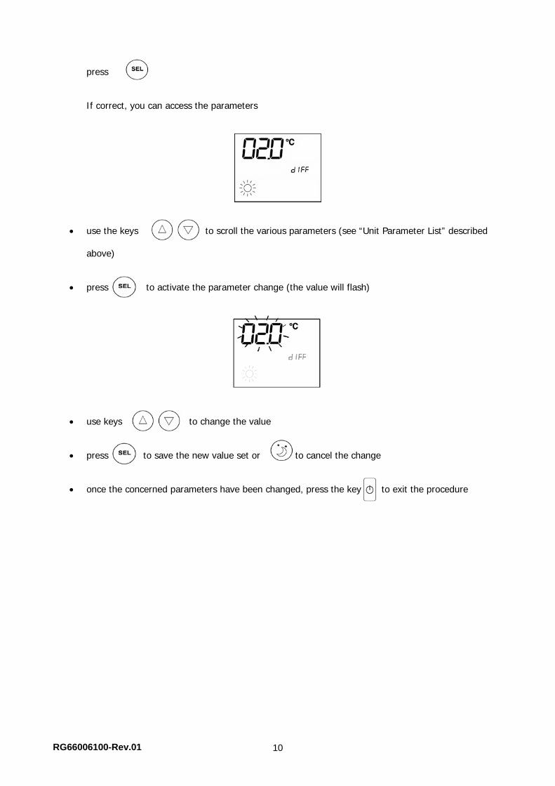
press . If correct, you can access the parameters
use the keys to scroll the various parameters (see “Unit Parameter List” described
above)
press to activate the parameter change (the value will flash)
use keys to change the value
press to save the new value set or to cancel the change
once the concerned parameters have been changed, press the key to exit the procedure
RG66006100-Rev.01 11
UNIT READINGS DISPLAY
Allows to display some values read by the controlled unit.
READINGS LIST
CURRENT SETPOINT (can be changed by compensations set on the unit)
EVAPORATOR OUTFEED WATER TEMPERATURE – CIRCUIT 1
CONDENSATION PRESSURE – CIRCUIT 1
EVAPORATOR OUTFEED WATER TEMPERATURE – CIRCUIT 2 (only if the number of circuits is set at 2)
CONDENSATION PRESSURE – CIRCUIT 2 (only if the number of circuits is set at 2)
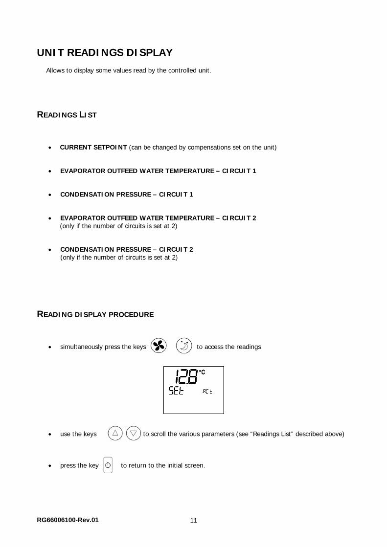
READING DISPLAY PROCEDURE
simultaneously press the keys to access the readings
use the keys to scroll the various parameters (see “Readings List” described above)
press the key to return to the initial screen.
RG66006100-Rev.01 12
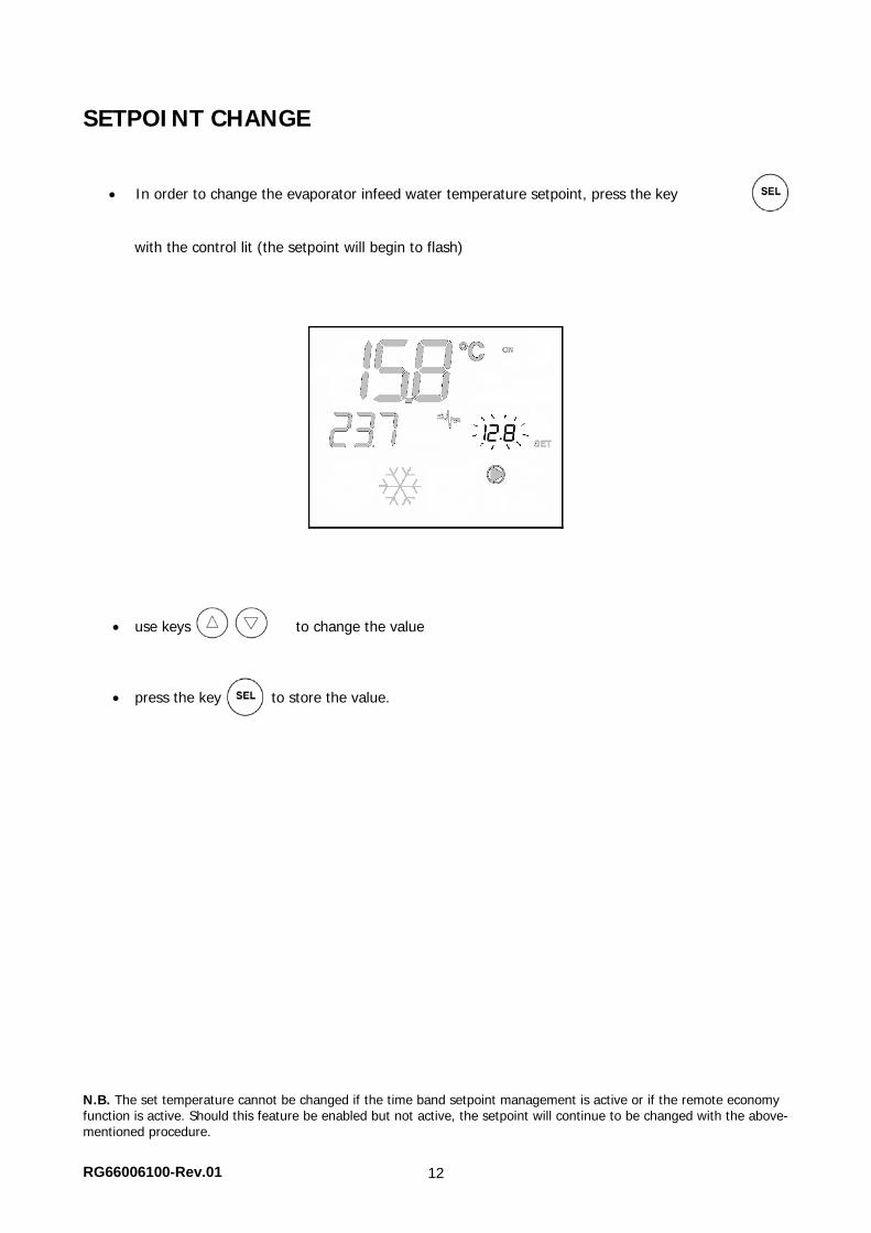
SETPOINT CHANGE
In order to change the evaporator infeed water temperature setpoint, press the key
with the control lit (the setpoint will begin to flash)
use keys to change the value
press the key to store the value. N.B. The set temperature cannot be changed if the time band setpoint management is active or if the remote economy function is active. Should this feature be enabled but not active, the setpoint will continue to be changed with the above-mentioned procedure.
RG66006100-Rev.01 13
TIME BAND CONFIGURATION (Only plus version)
GENERAL OPERATION
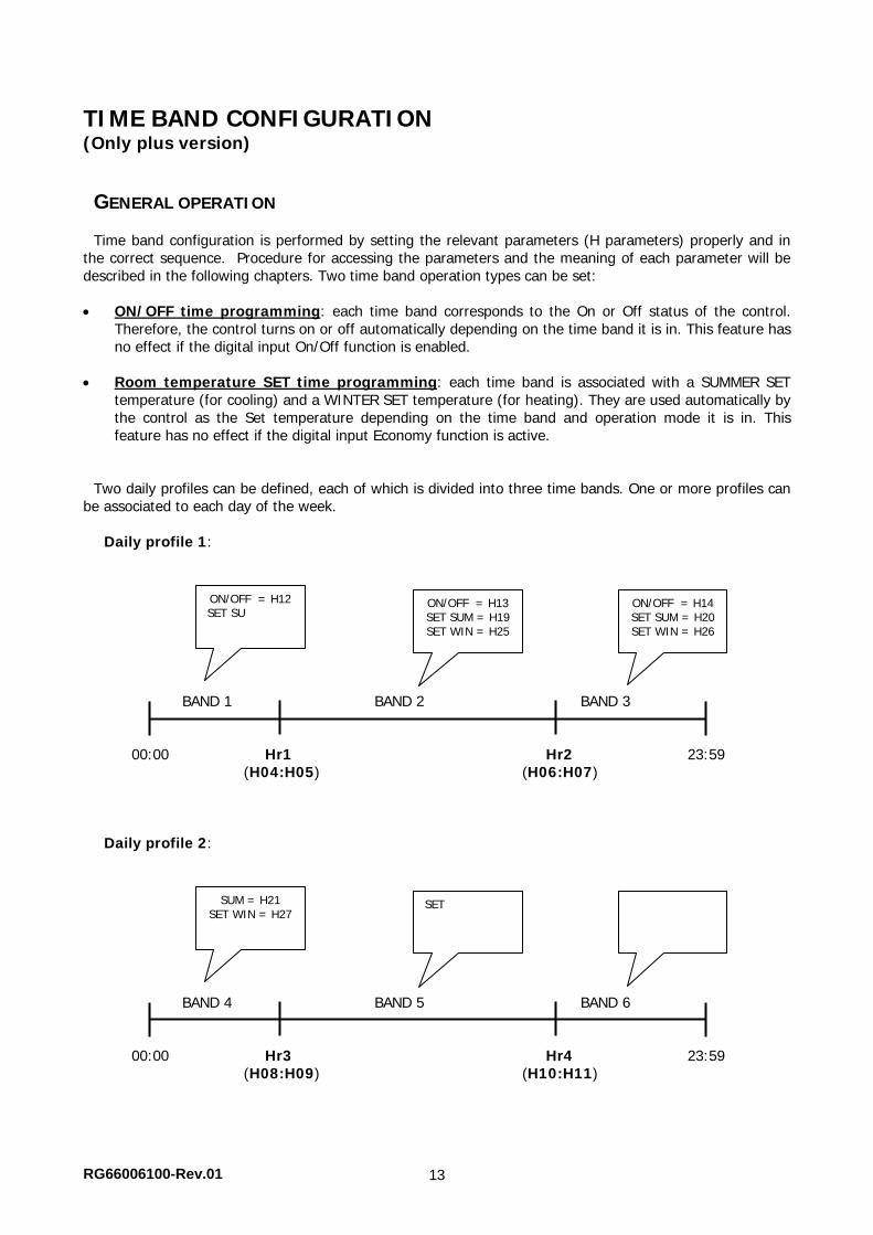
Time band configuration is performed by setting the relevant parameters (H parameters) properly and in the correct sequence. Procedure for accessing the parameters and the meaning of each parameter will be described in the following chapters. Two time band operation types can be set:
ON/OFF time programming: each time band corresponds to the On or Off status of the control.
Therefore, the control turns on or off automatically depending on the time band it is in. This feature has no effect if the digital input On/Off function is enabled.
Room temperature SET time programming: each time band is associated with a SUMMER SET temperature (for cooling) and a WINTER SET temperature (for heating). They are used automatically by the control as the Set temperature depending on the time band and operation mode it is in. This feature has no effect if the digital input Economy function is active.
Two daily profiles can be defined, each of which is divided into three time bands. One or more profiles can
be associated to each day of the week. Daily profile 1:
BAND 1 BAND 2 BAND 3 00:00 Hr1 Hr2 23:59 (H04:H05) (H06:H07) Daily profile 2:
BAND 4 BAND 5 BAND 6 00:00 Hr3 Hr4 23:59 (H08:H09) (H10:H11)
ON/OFF = H14 SET SUM = H20 SET WIN = H26
ON/OFF = H13 SET SUM = H19 SET WIN = H25
ON/OFF = H12 SET SU
SETSUM = H21 SET WIN = H27
RG66006100-Rev.01 14
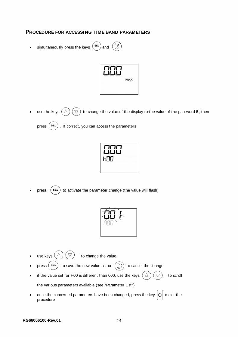
PROCEDURE FOR ACCESSING TIME BAND PARAMETERS
simultaneously press the keys and
use the keys to change the value of the display to the value of the password 5, then
press . If correct, you can access the parameters
press to activate the parameter change (the value will flash)
use keys to change the value press to save the new value set or to cancel the change
if the value set for H00 is different than 000, use the keys to scroll
the various parameters available (see “Parameter List”)
once the concerned parameters have been changed, press the key to exit the
procedure
RG66006100-Rev.01 15
PARAMETER LIST
Time band configuration is performed by setting the parameters found one at a time by scrolling with the
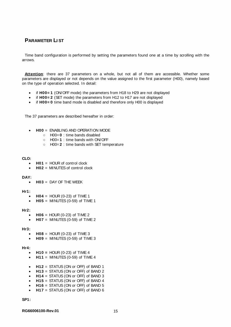
arrows. Attention: there are 37 parameters on a whole, but not all of them are accessible. Whether some
parameters are displayed or not depends on the value assigned to the first parameter (H00), namely based on the type of operation selected. In detail:
if H00=1 (ON/OFF mode) the parameters from H18 to H29 are not displayed if H00=2 (SET mode) the parameters from H12 to H17 are not displayed if H00=0 time band mode is disabled and therefore only H00 is displayed
The 37 parameters are described hereafter in order:
H00 = ENABLING AND OPERATION MODE
○ H00=0 : time bands disabled ○ H00=1 : time bands with ON/OFF ○ H00=2 : time bands with SET temperature
CLO:
H01 = HOUR of control clock H02 = MINUTES of control clock
DAY:
H03 = DAY OF THE WEEK Hr1:
H04 = HOUR (0-23) of TIME 1 H05 = MINUTES (0-59) of TIME 1
Hr2:
H06 = HOUR (0-23) of TIME 2 H07 = MINUTES (0-59) of TIME 2
Hr3:
H08 = HOUR (0-23) of TIME 3 H09 = MINUTES (0-59) of TIME 3
Hr4:
H10 = HOUR (0-23) of TIME 4 H11 = MINUTES (0-59) of TIME 4 H12 = STATUS (ON or OFF) of BAND 1 H13 = STATUS (ON or OFF) of BAND 2 H14 = STATUS (ON or OFF) of BAND 3 H15 = STATUS (ON or OFF) of BAND 4 H16 = STATUS (ON or OFF) of BAND 5 H17 = STATUS (ON or OFF) of BAND 6
SP1:
RG66006100-Rev.01 16
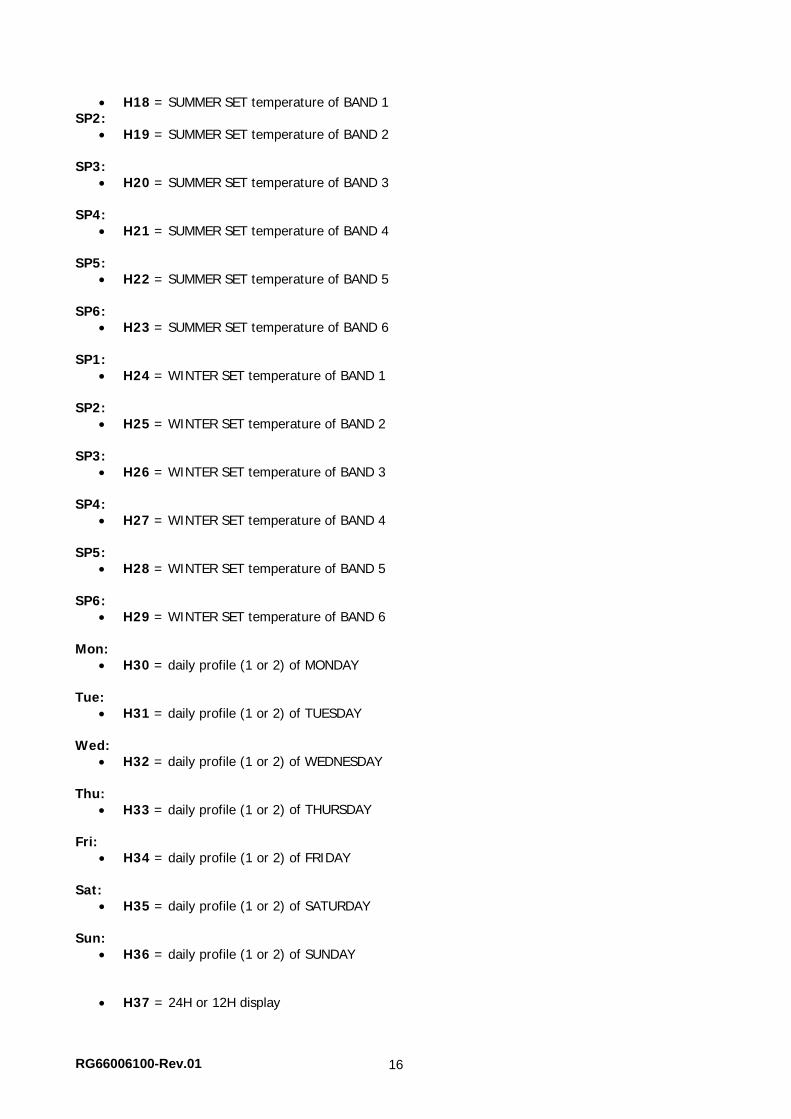
H18 = SUMMER SET temperature of BAND 1 SP2:
H19 = SUMMER SET temperature of BAND 2 SP3:
H20 = SUMMER SET temperature of BAND 3 SP4:
H21 = SUMMER SET temperature of BAND 4 SP5:
H22 = SUMMER SET temperature of BAND 5 SP6:
H23 = SUMMER SET temperature of BAND 6 SP1:
H24 = WINTER SET temperature of BAND 1 SP2:
H25 = WINTER SET temperature of BAND 2 SP3:
H26 = WINTER SET temperature of BAND 3 SP4:
H27 = WINTER SET temperature of BAND 4 SP5:
H28 = WINTER SET temperature of BAND 5 SP6:
H29 = WINTER SET temperature of BAND 6 Mon:
H30 = daily profile (1 or 2) of MONDAY Tue:
H31 = daily profile (1 or 2) of TUESDAY Wed:
H32 = daily profile (1 or 2) of WEDNESDAY Thu:
H33 = daily profile (1 or 2) of THURSDAY Fri:
H34 = daily profile (1 or 2) of FRIDAY Sat:
H35 = daily profile (1 or 2) of SATURDAY Sun:
H36 = daily profile (1 or 2) of SUNDAY
H37 = 24H or 12H display
RG66006100-Rev.01 17
PARAMETERS DEFAULT VALUES
H00 = 0 (time bands disabled)
Hr1 = 06:00
Hr2 = 22:00
Hr3 = 08:00
Hr4 = 20:00
H12 = OFF
H13 = ON
H14 = OFF
H15 = OFF
H16 = ON
H17 = OFF
H18-H23 = 12°C
H24-H29 = 45°C
H30-H34 = 1
H35-H36 = 2
H37 = 24H
If the 12H display is set (parameter 37), inside the configuration parameters from H01 to H 11 (except
H03) the progressive parameter number is not displayed except for the AM/PM time.
DISPLAY OF ACTUAL TIME If the time bands are enabled, when the thermostat is on, the clock symbol will always be displayed and the correctness of the set time can be checked (only for a few instants) by pressing the key
N.B. For remote control of units provided with a pCO processor with the clock board installed, management of the time bands is also implemented on the board software. If you wish to manage the time band with the Remote Control, this feature must not be enabled at the same time on the pCO board.
RG66006100-Rev.01 18
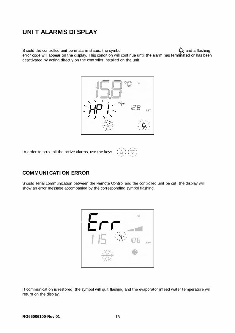
UNIT ALARMS DISPLAY Should the controlled unit be in alarm status, the symbol and a flashing error code will appear on the display. This condition will continue until the alarm has terminated or has been deactivated by acting directly on the controller installed on the unit.
In order to scroll all the active alarms, use the keys .
COMMUNICATION ERROR Should serial communication between the Remote Control and the controlled unit be cut, the display will show an error message accompanied by the corresponding symbol flashing.
If communication is restored, the symbol will quit flashing and the evaporator infeed water temperature will return on the display.
RG66006100-Rev.01 19
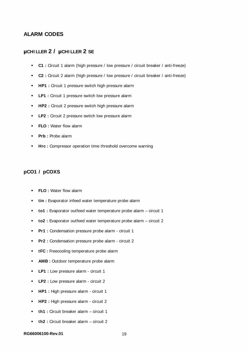
ALARM CODES
μCHILLER 2 / μCHILLER 2 SE
C1 : Circuit 1 alarm (high pressure / low pressure / circuit breaker / anti-freeze)
C2 : Circuit 2 alarm (high pressure / low pressure / circuit breaker / anti-freeze)
HP1 : Circuit 1 pressure switch high pressure alarm
LP1 : Circuit 1 pressure switch low pressure alarm
HP2 : Circuit 2 pressure switch high pressure alarm LP2 : Circuit 2 pressure switch low pressure alarm
FLO : Water flow alarm
Prb : Probe alarm
Hrc : Compressor operation time threshold overcome warning
pCO1 / pCOXS
FLO : Water flow alarm
tin : Evaporator infeed water temperature probe alarm
to1 : Evaporator outfeed water temperature probe alarm – circuit 1
to2 : Evaporator outfeed water temperature probe alarm – circuit 2
Pr1 : Condensation pressure probe alarm - circuit 1
Pr2 : Condensation pressure probe alarm - circuit 2
tFC : Freecooling temperature probe alarm
AMB : Outdoor temperature probe alarm
LP1 : Low pressure alarm - circuit 1
LP2 : Low pressure alarm - circuit 2
HP1 : High pressure alarm - circuit 1
HP2 : High pressure alarm - circuit 2
th1 : Circuit breaker alarm – circuit 1
th2 : Circuit breaker alarm – circuit 2
RG66006100-Rev.01 20
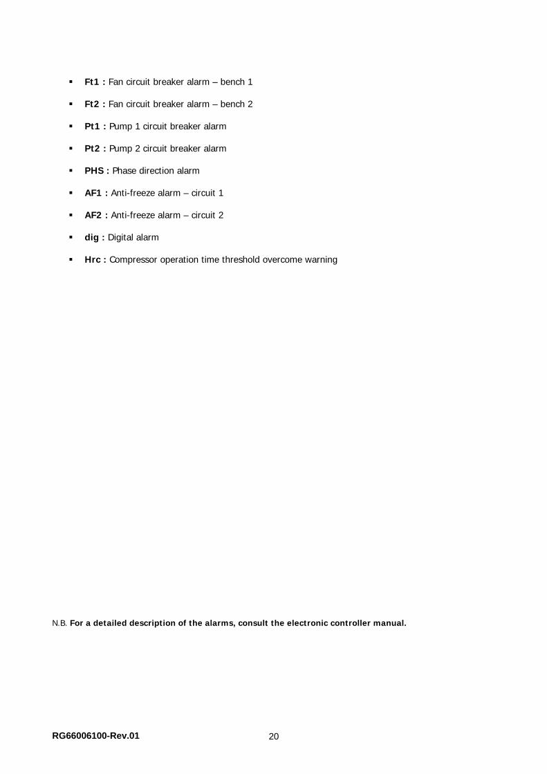
Ft1 : Fan circuit breaker alarm – bench 1
Ft2 : Fan circuit breaker alarm – bench 2
Pt1 : Pump 1 circuit breaker alarm
Pt2 : Pump 2 circuit breaker alarm
PHS : Phase direction alarm
AF1 : Anti-freeze alarm – circuit 1
AF2 : Anti-freeze alarm – circuit 2
dig : Digital alarm
Hrc : Compressor operation time threshold overcome warning
N.B. For a detailed description of the alarms, consult the electronic controller manual.
RG66006100-Rev.01 21
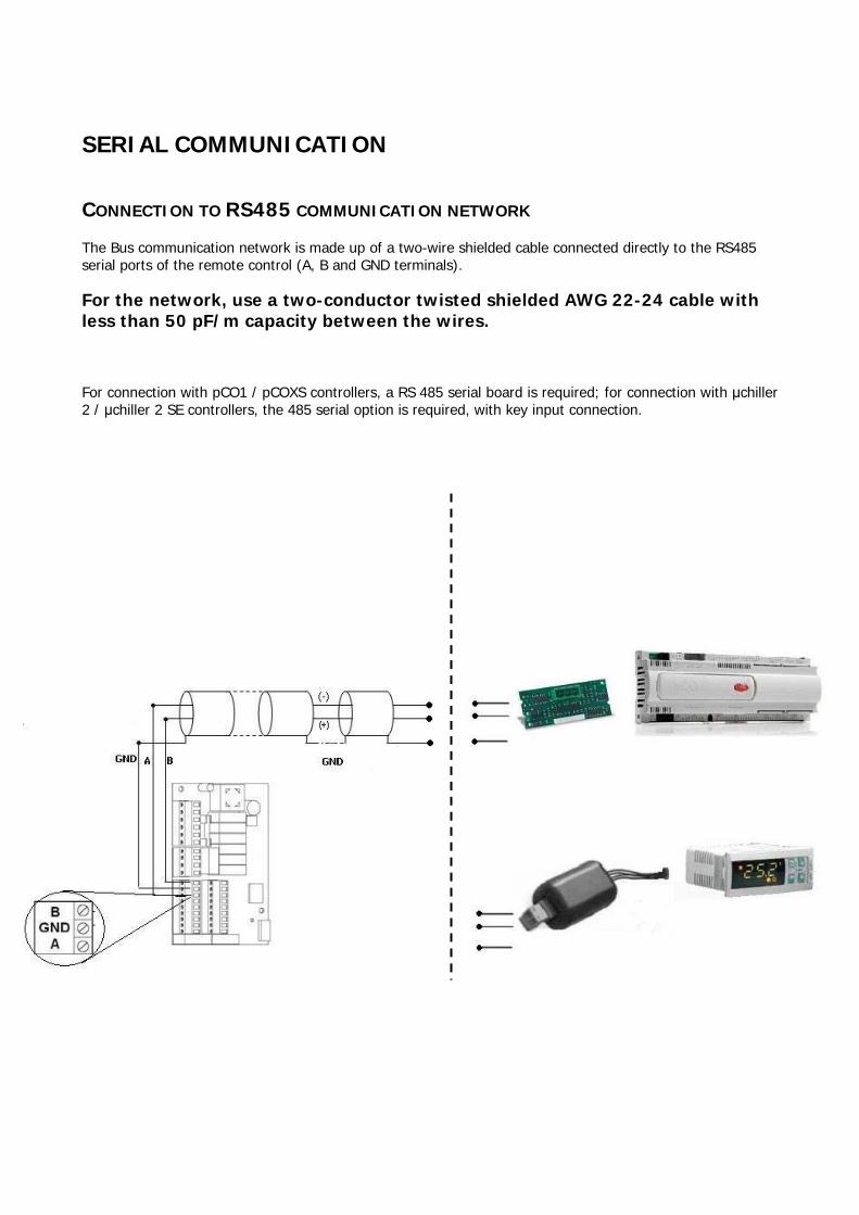
SERIAL COMMUNICATION
CONNECTION TO RS485 COMMUNICATION NETWORK
The Bus communication network is made up of a two-wire shielded cable connected directly to the RS485 serial ports of the remote control (A, B and GND terminals). For the network, use a two-conductor twisted shielded AWG 22-24 cable with less than 50 pF/m capacity between the wires. For connection with pCO1 / pCOXS controllers, a RS 485 serial board is required; for connection with μchiller 2 / μchiller 2 SE controllers, the 485 serial option is required, with key input connection.
RG66006100-Rev.01 22
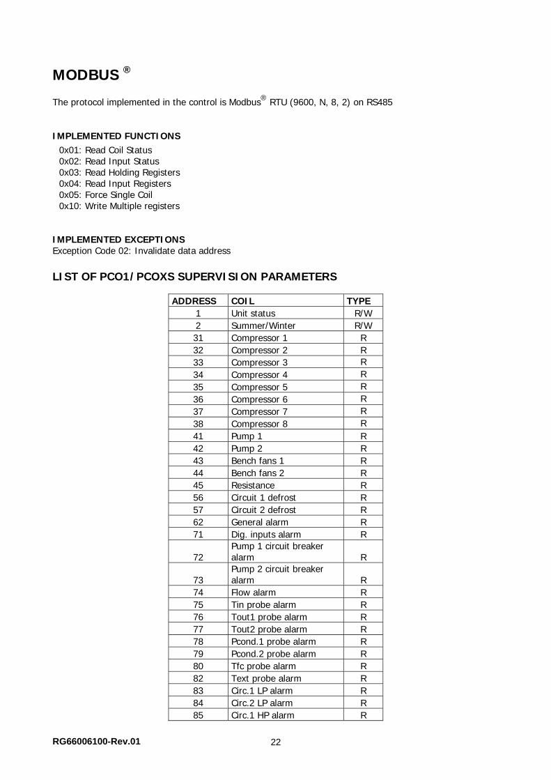
MODBUS ® The protocol implemented in the control is Modbus®
RTU (9600, N, 8, 2) on RS485
IMPLEMENTED FUNCTIONS 0x01: Read Coil Status 0x02: Read Input Status 0x03: Read Holding Registers 0x04: Read Input Registers 0x05: Force Single Coil 0x10: Write Multiple registers
IMPLEMENTED EXCEPTIONS Exception Code 02: Invalidate data address LIST OF PCO1/PCOXS SUPERVISION PARAMETERS
ADDRESS COIL TYPE 1 Unit status R/W 2 Summer/Winter R/W 31 Compressor 1 R 32 Compressor 2 R 33 Compressor 3 R 34 Compressor 4 R 35 Compressor 5 R 36 Compressor 6 R 37 Compressor 7 R 38 Compressor 8 R 41 Pump 1 R 42 Pump 2 R 43 Bench fans 1 R 44 Bench fans 2 R 45 Resistance R 56 Circuit 1 defrost R 57 Circuit 2 defrost R 62 General alarm R 71 Dig. inputs alarm R
72 Pump 1 circuit breaker alarm R
73 Pump 2 circuit breaker alarm R
74 Flow alarm R 75 Tin probe alarm R 76 Tout1 probe alarm R 77 Tout2 probe alarm R 78 Pcond.1 probe alarm R 79 Pcond.2 probe alarm R 80 Tfc probe alarm R 82 Text probe alarm R 83 Circ.1 LP alarm R 84 Circ.2 LP alarm R 85 Circ.1 HP alarm R
RG66006100-Rev.01 23
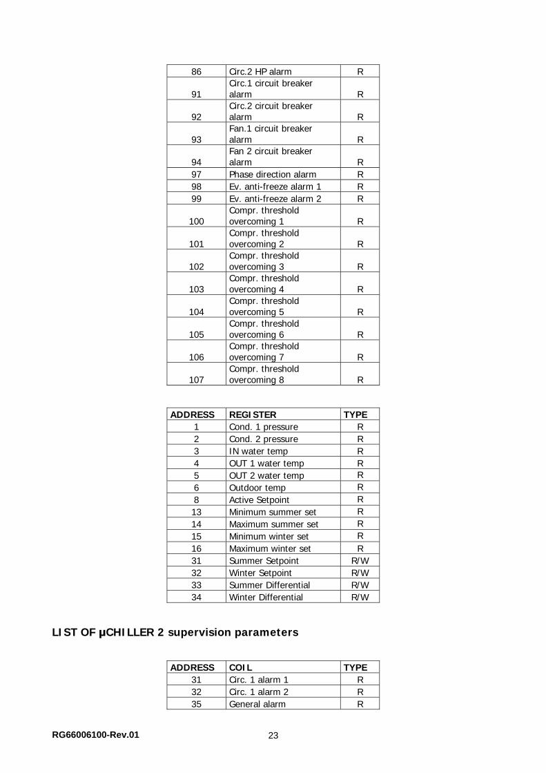
86 Circ.2 HP alarm R
91 Circ.1 circuit breaker alarm R
92 Circ.2 circuit breaker alarm R
93 Fan.1 circuit breaker alarm R
94 Fan 2 circuit breaker alarm R
97 Phase direction alarm R 98 Ev. anti-freeze alarm 1 R 99 Ev. anti-freeze alarm 2 R
100 Compr. threshold overcoming 1 R
101 Compr. threshold overcoming 2 R
102 Compr. threshold overcoming 3 R
103 Compr. threshold overcoming 4 R
104 Compr. threshold overcoming 5 R
105 Compr. threshold overcoming 6 R
106 Compr. threshold overcoming 7 R
107 Compr. threshold overcoming 8 R
ADDRESS REGISTER TYPE 1 Cond. 1 pressure R 2 Cond. 2 pressure R 3 IN water temp R 4 OUT 1 water temp R 5 OUT 2 water temp R 6 Outdoor temp R 8 Active Setpoint R 13 Minimum summer set R 14 Maximum summer set R 15 Minimum winter set R 16 Maximum winter set R 31 Summer Setpoint R/W 32 Winter Setpoint R/W 33 Summer Differential R/W 34 Winter Differential R/W
LIST OF μCHILLER 2 supervision parameters
ADDRESS COIL TYPE 31 Circ. 1 alarm 1 R 32 Circ. 1 alarm 2 R 35 General alarm R
RG66006100-Rev.01 24
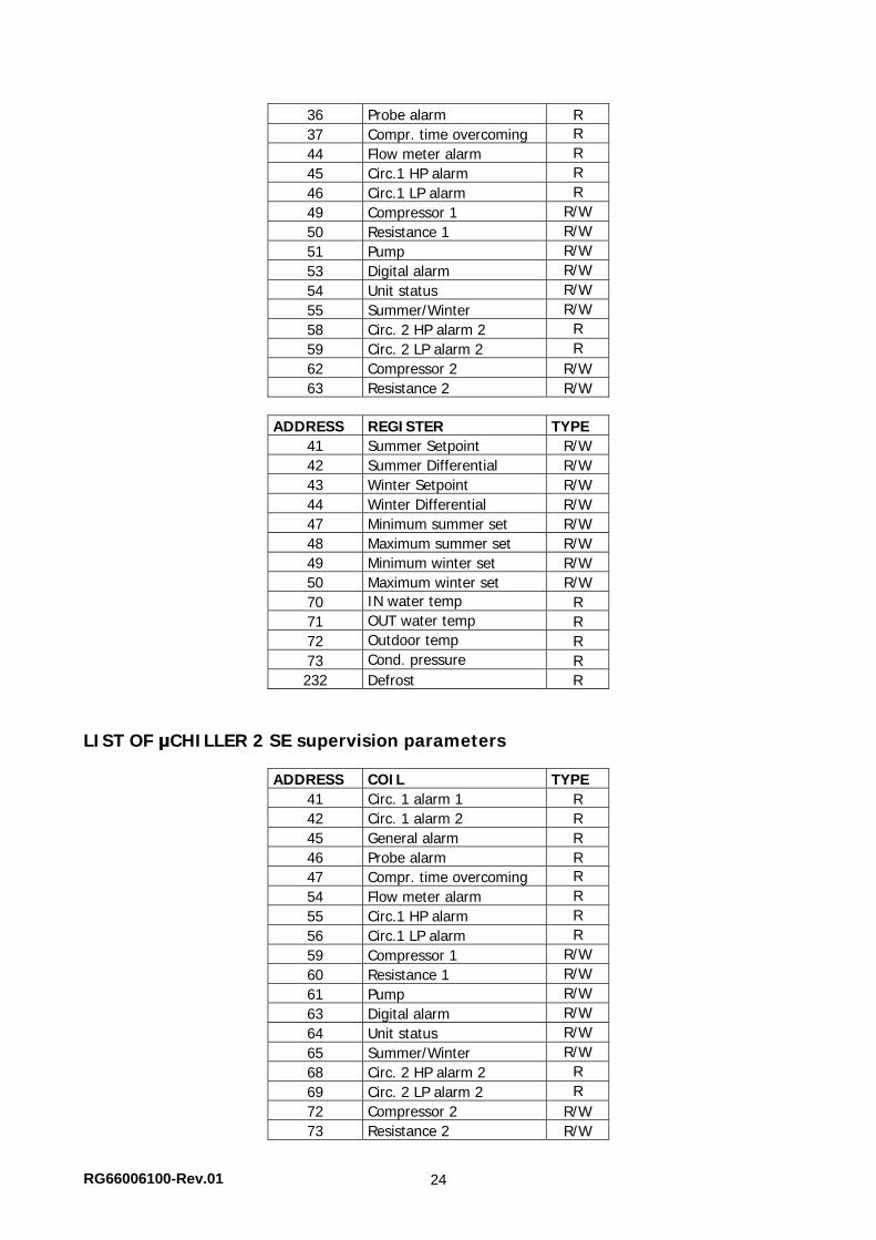
36 Probe alarm R 37 Compr. time overcoming R 44 Flow meter alarm R 45 Circ.1 HP alarm R 46 Circ.1 LP alarm R 49 Compressor 1 R/W 50 Resistance 1 R/W 51 Pump R/W 53 Digital alarm R/W 54 Unit status R/W 55 Summer/Winter R/W 58 Circ. 2 HP alarm 2 R 59 Circ. 2 LP alarm 2 R 62 Compressor 2 R/W 63 Resistance 2 R/W
ADDRESS REGISTER TYPE
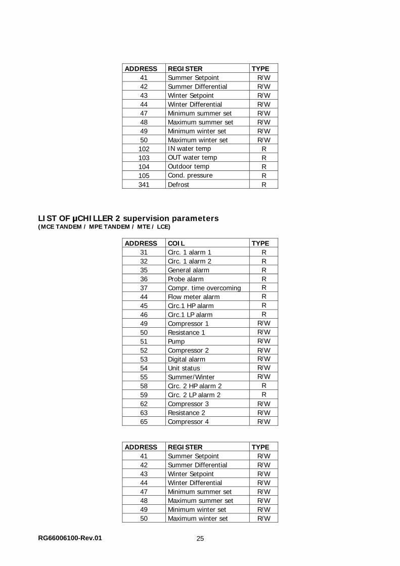
41 Summer Setpoint R/W 42 Summer Differential R/W 43 Winter Setpoint R/W 44 Winter Differential R/W 47 Minimum summer set R/W 48 Maximum summer set R/W 49 Minimum winter set R/W 50 Maximum winter set R/W 70 IN water temp R 71 OUT water temp R 72 Outdoor temp R 73 Cond. pressure R 232 Defrost R
LIST OF μCHILLER 2 SE supervision parameters
ADDRESS COIL TYPE 41 Circ. 1 alarm 1 R 42 Circ. 1 alarm 2 R 45 General alarm R 46 Probe alarm R 47 Compr. time overcoming R 54 Flow meter alarm R 55 Circ.1 HP alarm R 56 Circ.1 LP alarm R 59 Compressor 1 R/W 60 Resistance 1 R/W 61 Pump R/W 63 Digital alarm R/W 64 Unit status R/W 65 Summer/Winter R/W 68 Circ. 2 HP alarm 2 R 69 Circ. 2 LP alarm 2 R 72 Compressor 2 R/W 73 Resistance 2 R/W
RG66006100-Rev.01 25
ADDRESS REGISTER TYPE 41 Summer Setpoint R/W 42 Summer Differential R/W 43 Winter Setpoint R/W 44 Winter Differential R/W 47 Minimum summer set R/W 48 Maximum summer set R/W 49 Minimum winter set R/W 50 Maximum winter set R/W 102 IN water temp R 103 OUT water temp R 104 Outdoor temp R 105 Cond. pressure R 341 Defrost R
LIST OF μCHILLER 2 supervision parameters (MCE TANDEM / MPE TANDEM / MTE / LCE)
ADDRESS COIL TYPE 31 Circ. 1 alarm 1 R 32 Circ. 1 alarm 2 R 35 General alarm R 36 Probe alarm R 37 Compr. time overcoming R 44 Flow meter alarm R 45 Circ.1 HP alarm R 46 Circ.1 LP alarm R 49 Compressor 1 R/W 50 Resistance 1 R/W 51 Pump R/W 52 Compressor 2 R/W 53 Digital alarm R/W 54 Unit status R/W 55 Summer/Winter R/W 58 Circ. 2 HP alarm 2 R 59 Circ. 2 LP alarm 2 R 62 Compressor 3 R/W 63 Resistance 2 R/W 65 Compressor 4 R/W
ADDRESS REGISTER TYPE 41 Summer Setpoint R/W 42 Summer Differential R/W 43 Winter Setpoint R/W 44 Winter Differential R/W 47 Minimum summer set R/W 48 Maximum summer set R/W 49 Minimum winter set R/W 50 Maximum winter set R/W
RG66006100-Rev.01 26
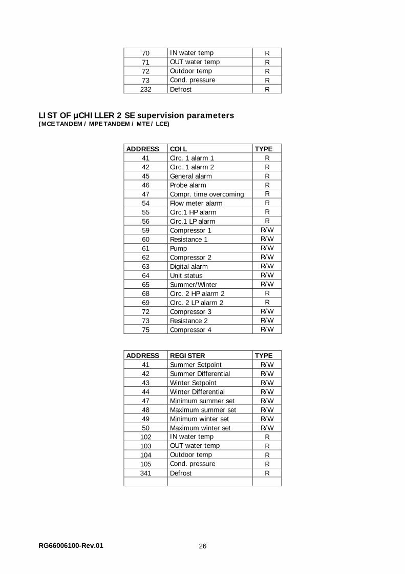
70 IN water temp R 71 OUT water temp R 72 Outdoor temp R 73 Cond. pressure R 232 Defrost R
LIST OF μCHILLER 2 SE supervision parameters (MCE TANDEM / MPE TANDEM / MTE / LCE)
ADDRESS COIL TYPE 41 Circ. 1 alarm 1 R 42 Circ. 1 alarm 2 R 45 General alarm R 46 Probe alarm R 47 Compr. time overcoming R 54 Flow meter alarm R 55 Circ.1 HP alarm R 56 Circ.1 LP alarm R 59 Compressor 1 R/W 60 Resistance 1 R/W 61 Pump R/W 62 Compressor 2 R/W 63 Digital alarm R/W 64 Unit status R/W 65 Summer/Winter R/W 68 Circ. 2 HP alarm 2 R 69 Circ. 2 LP alarm 2 R 72 Compressor 3 R/W 73 Resistance 2 R/W 75 Compressor 4 R/W
ADDRESS REGISTER TYPE 41 Summer Setpoint R/W 42 Summer Differential R/W 43 Winter Setpoint R/W 44 Winter Differential R/W 47 Minimum summer set R/W 48 Maximum summer set R/W 49 Minimum winter set R/W 50 Maximum winter set R/W 102 IN water temp R 103 OUT water temp R 104 Outdoor temp R 105 Cond. pressure R 341 Defrost R
RG66006100-Rev.01 27
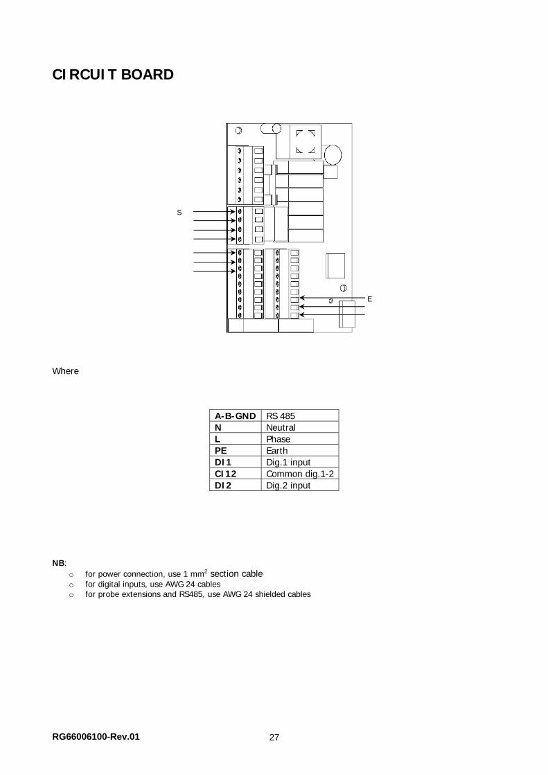
CIRCUIT BOARD
Where
A-B-GND RS 485 N Neutral L Phase PE Earth DI1 Dig.1 input CI12 Common dig.1-2DI2 Dig.2 input
NB:
o for power connection, use 1 mm2 section cable o for digital inputs, use AWG 24 cables o for probe extensions and RS485, use AWG 24 shielded cables
E
S
RG66006100-Rev.01 28
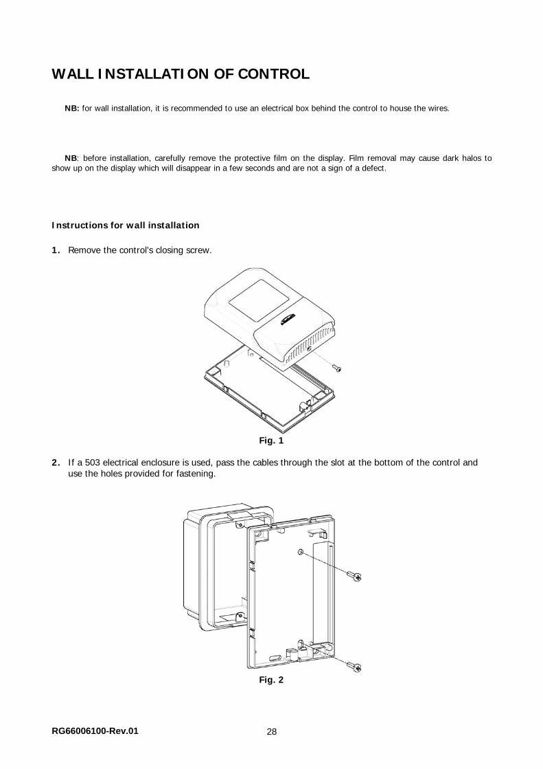
WALL INSTALLATION OF CONTROL
NB: for wall installation, it is recommended to use an electrical box behind the control to house the wires.
NB: before installation, carefully remove the protective film on the display. Film removal may cause dark halos to show up on the display which will disappear in a few seconds and are not a sign of a defect.
Instructions for wall installation 1. Remove the control's closing screw.
Fig. 1
2. If a 503 electrical enclosure is used, pass the cables through the slot at the bottom of the control and
use the holes provided for fastening.
Fig. 2
RG66006100-Rev.01 29
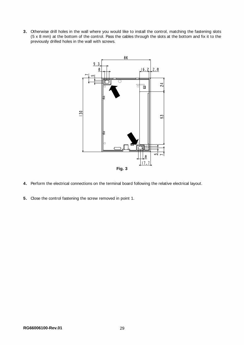
3. Otherwise drill holes in the wall where you would like to install the control, matching the fastening slots (5 x 8 mm) at the bottom of the control. Pass the cables through the slots at the bottom and fix it to the previously drilled holes in the wall with screws.
Fig. 3
4. Perform the electrical connections on the terminal board following the relative electrical layout.
5. Close the control fastening the screw removed in point 1.
RG66006100-Rev.01 30
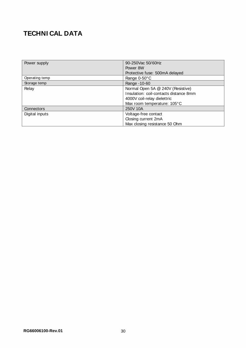
TECHNICAL DATA Power supply 90-250Vac 50/60Hz
Power 8W Protective fuse: 500mA delayed
Operating temp Range 0-50°C Storage temp Range -10-60� Relay Normal Open 5A @ 240V (Resistive)
Insulation: coil-contacts distance 8mm 4000V coil-relay dielettric Max room temperature: 105°C
Connectors 250V 10A Digital inputs Voltage-free contact
Closing current 2mA Max closing resistance 50 Ohm

NOTES

40010 Bentivoglio (BO)Via Romagnoli 12/aTel. 051/8908111Fax. 051/8908122
www.galletti.itCompany UNI EN ISO 9001 and OHSAS 18001 certified