BCL-1 remote control clock specification - Banggoodfiles.banggood.com/2016/08/SKU206184-en.doc ·...
18
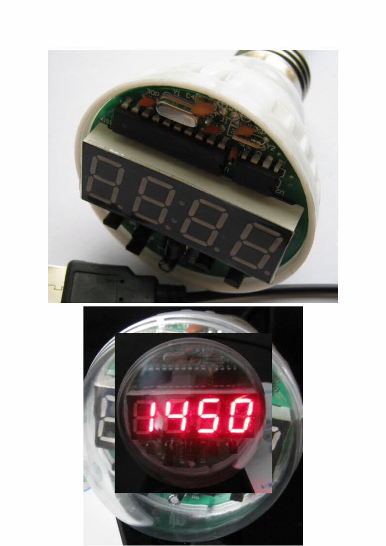
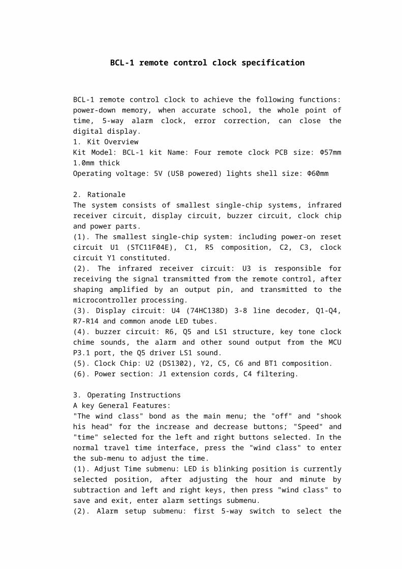
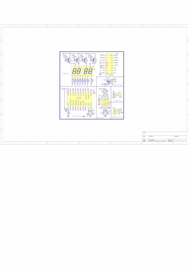
BCL-1 remote control clock specification BCL-1 remote control clock to achieve the following functions: power-down memory, when accurate school, the whole point of time, 5-way alarm clock, error correction, can close the digital display. 1. Kit Overview Kit Model: BCL-1 kit Name: Four remote clock PCB size: Φ57mm 1.0mm thick Operating voltage: 5V (USB powered) lights shell size: Φ60mm 2. Rationale The system consists of smallest single-chip systems, infrared receiver circuit, display circuit, buzzer circuit, clock chip and power parts. (1). The smallest single-chip system: including power-on reset circuit U1 (STC11F04E), C1, R5 composition, C2, C3, clock circuit Y1 constituted. (2). The infrared receiver circuit: U3 is responsible for receiving the signal transmitted from the remote control, after shaping amplified by an output pin, and transmitted to the microcontroller processing. (3). Display circuit: U4 (74HC138D) 3-8 line decoder, Q1-Q4, R7-R14 and common anode LED tubes. (4). buzzer circuit: R6, Q5 and LS1 structure, key tone clock chime sounds, the alarm and other sound output from the MCU P3.1 port, the Q5 driver LS1 sound. (5). Clock Chip: U2 (DS1302), Y2, C5, C6 and BT1 composition. (6). Power section: J1 extension cords, C4 filtering. 3. Operating Instructions A key General Features: "The wind class" bond as the main menu; the "off" and "shook his head" for the increase and decrease buttons; "Speed" and "time" selected for the left and right buttons selected. In the normal travel time interface, press the "wind class" to enter the sub-menu to adjust the time. (1). Adjust Time submenu: LED is blinking position is currently selected position, after adjusting the hour and minute by subtraction and left and right keys, then press "wind class" to save and exit, enter alarm settings submenu. (2). Alarm setup submenu: first 5-way switch to select the
Transcript of BCL-1 remote control clock specification - Banggoodfiles.banggood.com/2016/08/SKU206184-en.doc ·...
BCL-1 remote control clock specification
BCL-1 remote control clock to achieve the following functions: power-down memory, when accurate school, the whole point of time, 5-way alarm clock, error correction, can close the digital display.1. Kit OverviewKit Model: BCL-1 kit Name: Four remote clock PCB size: Φ57mm 1.0mm thickOperating voltage: 5V (USB powered) lights shell size: Φ60mm
2. RationaleThe system consists of smallest single-chip systems, infrared receiver circuit, display circuit, buzzer circuit, clock chip and power parts.(1). The smallest single-chip system: including power-on reset circuit U1 (STC11F04E), C1, R5 composition, C2, C3, clock circuit Y1 constituted.(2). The infrared receiver circuit: U3 is responsible for receiving the signal transmitted from the remote control, after shaping amplified by an output pin, and transmitted to the microcontroller processing.(3). Display circuit: U4 (74HC138D) 3-8 line decoder, Q1-Q4, R7-R14 and common anode LED tubes.(4). buzzer circuit: R6, Q5 and LS1 structure, key tone clock chime sounds, the alarm and other sound output from the MCU P3.1 port, the Q5 driver LS1 sound.(5). Clock Chip: U2 (DS1302), Y2, C5, C6 and BT1 composition.(6). Power section: J1 extension cords, C4 filtering.
3. Operating InstructionsA key General Features:"The wind class" bond as the main menu; the "off" and "shook his head" for the increase and decrease buttons; "Speed" and "time" selected for the left and right buttons selected. In the normal travel time interface, press the "wind class" to enter the sub-menu to adjust the time.(1). Adjust Time submenu: LED is blinking position is currently selected position, after adjusting the hour and minute by subtraction and left and right keys, then press "wind class" to save and exit, enter alarm settings submenu.(2). Alarm setup submenu: first 5-way switch to select the alarm total, the first shows C, will display two flashing ON (on) or OF (off), the plus or minus key switch. If you choose OF (off), then press the "wind class" directly into the Error Correction submenu. If you choose 0N (on), then press the "wind class" to enter the alarm setting for each channel to channel 1 alarm for example. Show C1, after two flashing ON (on) or OF (off), on and off the set as above, if the election OF (off), then press the "wind class" directly into the second channel alarm ON (open) or OF (off) choice; if yes 0N (on), then press the "wind class" to enter the hours and minutes, the settings are consistent with the method and adjust the time setting is completed and then press the "wind" entry 2-way alarm set, the first 5-way alarm settings and then press "wind" entry error correction submenu.(3). Error Correction submenu: the first shows N, after two flashing ON (open amended) or OF (closed amendments), the plus or minus key switch, if you choose OF (closed
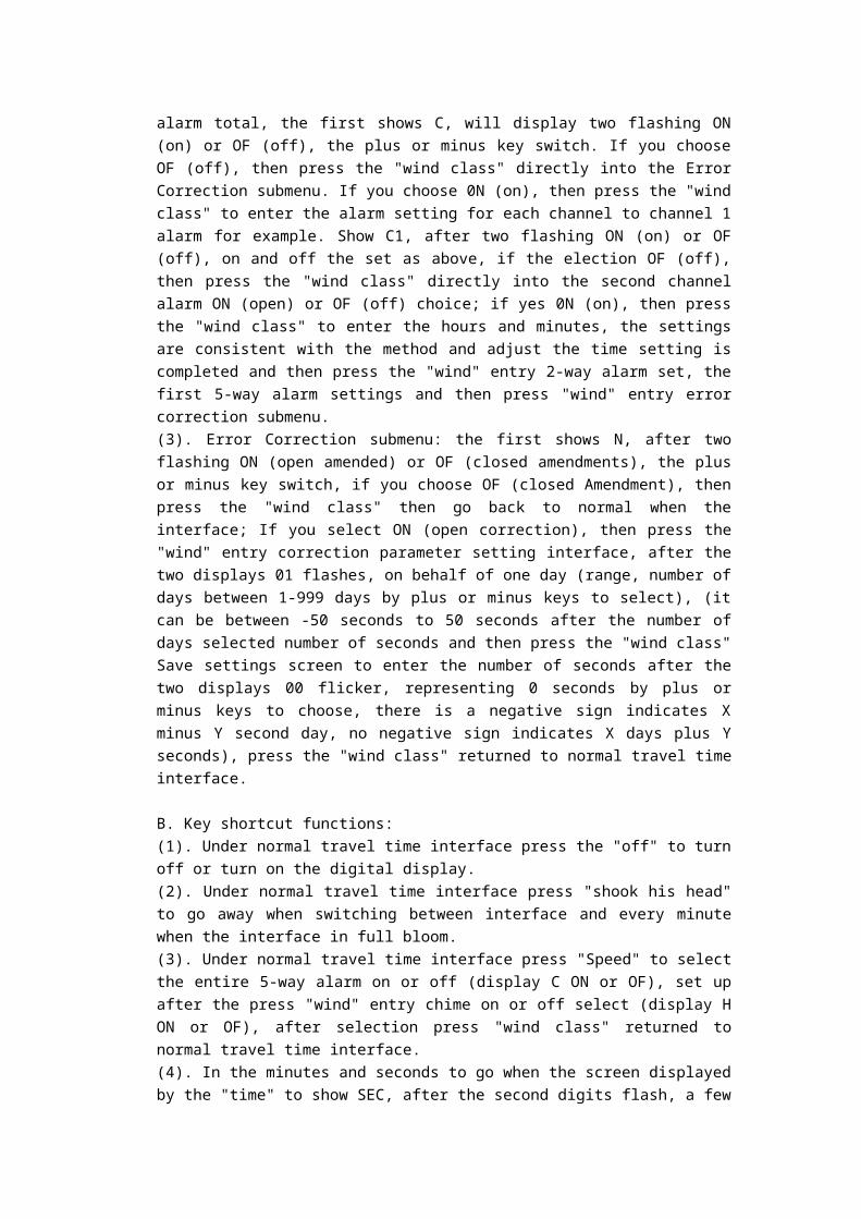
Amendment), then press the "wind class" then go back to normal when the interface; If you select ON (open correction), then press the "wind" entry correction parameter setting interface, after the two displays 01 flashes, on behalf of one day (range, number of days between 1-999 days by plus or minus keys to select), (it can be between -50 seconds to 50 seconds after the number of days selected number of seconds and then press the "wind class" Save settings screen to enter the number of seconds after the two displays 00 flicker, representing 0 seconds by plus or minus keys to choose, there is a negative sign indicates X minus Y second day, no negative sign indicates X days plus Y seconds), press the "wind class" returned to normal travel time interface.
B. Key shortcut functions:(1). Under normal travel time interface press the "off" to turn off or turn on the digital display.(2). Under normal travel time interface press "shook his head" to go away when switching between interface and every minute when the interface in full bloom.(3). Under normal travel time interface press "Speed" to select the entire 5-way alarm on or off (display C ON or OF), set up after the press "wind" entry chime on or off select (display H ON or OF), after selection press "wind class" returned to normal travel time interface.(4). In the minutes and seconds to go when the screen displayed by the "time" to show SEC, after the second digits flash, a few seconds after a little bit and the second sub-bit flash together, then another precise time control press "timer" again to the zero seconds, minutes and seconds to go when finally returns to the interface, you can check whether a second correction precision.
1. Electric circuit schematic diagram

1 2 3 4 5 6
A
B
C
D
654321
D
C
B
A
Title
Number RevisionSize
B
Date: 21-May-2013 Sheet of File: F:\ \ .Ddb设计实训套件实训套件二组 Drawn By:
RET
1
RX
D P
3.0
2
TXD
P3.
13
INT0
P3.
26
INT1
P3.
37
T0 P
3.4
8
T1 P
3.5
9
P3.7
11
X1
4
X2
5G
ND
10
P1.1
A1(
+)13
P1.0
A1(
-)12
P1.2
14
P1.3
15
P1.4
16
P1.5
17
P1.6
18
P1.7
19
VC
C20
U1
STC11F04E
A1
B2
C3
D4
E5
F6
G7
1H9
DP
8
2H10
3H11
4H12
DS1
4DISP
Y2
32.768
V2
1
OSC
2
OSC
3
GN
D4
RST
5I/0
6C
LK7
V1
8
U2
DS1
302
GND 2
VCC 3
OUT 1U3
VS1738
P3.3
P3.4
P3.5
P3.7
+5V
BT1
3V
P3.0
P3.0
P3.5
P3.7
P3.2 P3.2
+5V
P3.1
LS1+5V
P3.1
+5V
+5V
R110K
R6
10K
R510K
R210K R310K R410K
Q1 9012 Q2 9012 Q3 9012 Q4 9012
Q5
9012
Y112M
C1
10uF
C230P
C3
30P
C4
104
+5V
12
J1
CON2
A1
B2
C3
G2A4
G2B5
G16
Y77
GND8 Y6 9
Y5 10
Y4 11
Y3 12
Y2 13
Y1 14
Y0 15
VCC 16
U4 74HC138N
R7560
R8560
R9560
R10560
R11560
R12560
R13560
R14560
P3.3
P3.4 L1
L2
L3
L4
+5V
+5V
C66P
C56P
L1 L2 L3 L4
A B C D E F G DP
A B C D E F G DP
R1610K
R1510K
+5V
单片机最小系统 红外接收电路
电源供电
时钟芯片
蜂鸣器电路
显示电路
1 2 3 4 5 6
A
B
C
D
654321
D
C
B
A
Title
Number RevisionSize
B
Date: 21-May-2013 Sheet of File: F:\ \ ,PCB\ .Ddb红外遥控系统原理图 红外遥控系统Drawn By:
Q1
C2C1
+ C3
Y1
C1
1
C2
2
K1
3
K2
4
K3
5
K4
6
K5
7
VSS
8K6
9
K7
10
K8
11
OSC
212
OSC
113
LED
14
DO
15
VDD
16
U1 S4 S5S3S1 S2
GND
GND
D1LED
12
J1
关机开机 风类定时摇头
S6
调速
遥控器电路
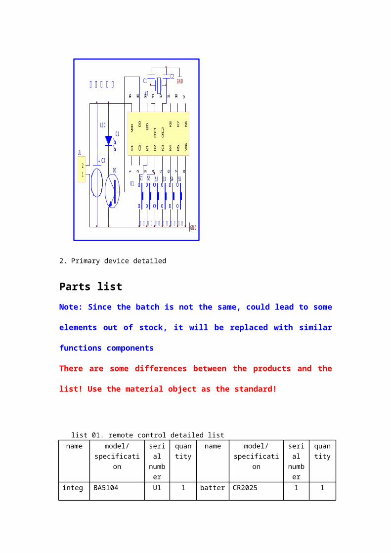
2. Primary device detailed
Parts listNote: Since the batch is not the same, could lead to some elements out of stock, it will be replaced with similar functions components There are some differences between the products and the list! Use the material object as the standard!
list 01. remote control detailed list name model/
specificationserial numb
er
quantity
name model/specification
serial numb
er
quantity
integrated circuit
BA5104 U1 1 battery CR2025 1 1
Triode S8050 Q1 1 battery shrapnel
Positive and negative x 1
J1 2
electric capacity
100P(0805) C1 C2
2 screw 1.4*3 1 5
22uF/25V C3 1 PCB 76*30.5mm 1 1crystal 455E Y1 1 pressed 8.30E+39 1 1
oscillator
key pastes membrane
infrared launching tube
Φ3 D1 1 outer case
86*40*6mm 1 1
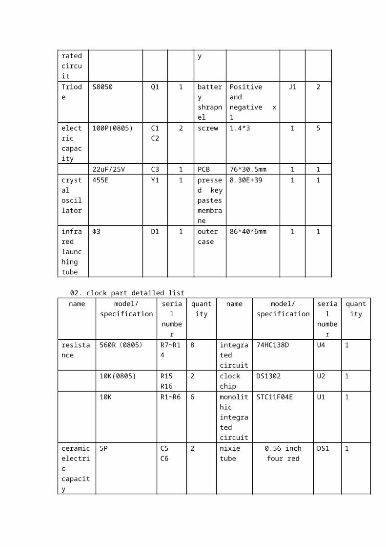
02. clock part detailed list name model/specification serial
numberquantity name model/specification serial
numberquantity
resistance 560R(0805) R7~R14 8 integrated circuit
74HC138D U4 1
10K(0805) R15 R16
2 clock chip DS1302 U2 1
10K R1~R6 6 monolithic integrated circuit
STC11F04E U1 1
ceramic electric capacity
5P C5 C6 2 nixie tube 0.56 inch four red DS1 1
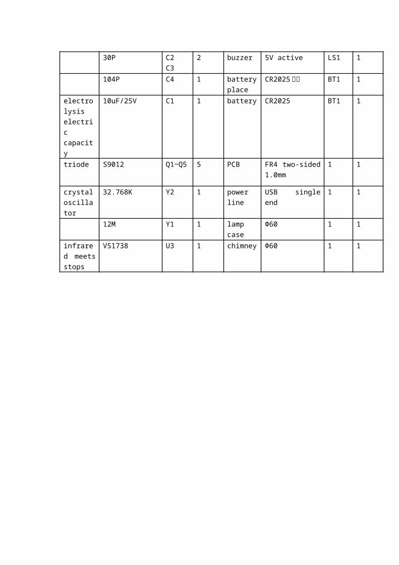
30P C2 C3 2 buzzer 5V active LS1 1 104P C4 1 battery
placeCR2025座子 BT1 1
electrolysis electric capacity
10uF/25V C1 1 battery CR2025 BT1 1
triode S9012 Q1~Q5 5 PCB FR4 two-sided 1.0mm
1 1
crystal oscillator
32.768K Y2 1 power line USB single end 1 1
12M Y1 1 lamp case Φ60 1 1infrared meets stops
VS1738 U3 1 chimney Φ60 1 1
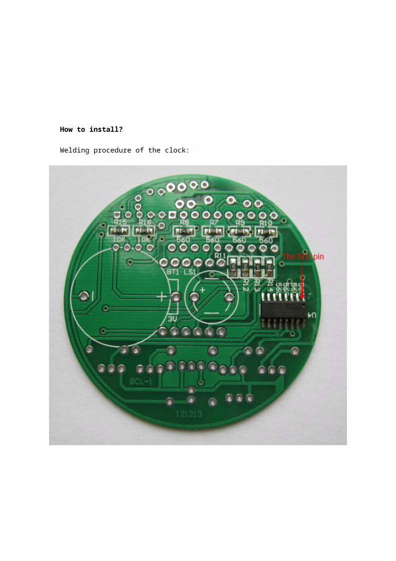
How to install?
Welding procedure of the clock:
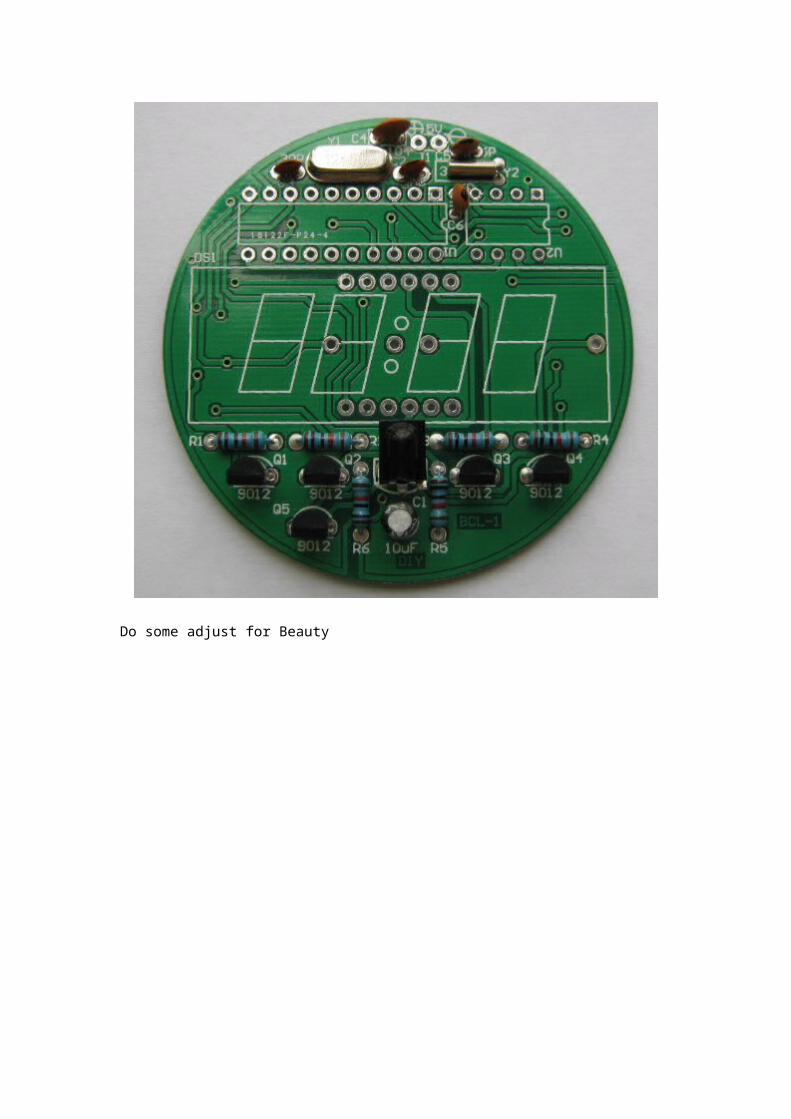
Do some adjust for Beauty
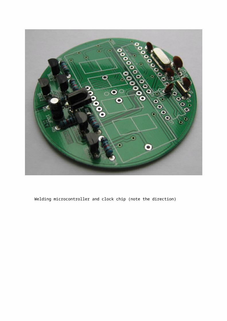
Welding microcontroller and clock chip (note the direction)
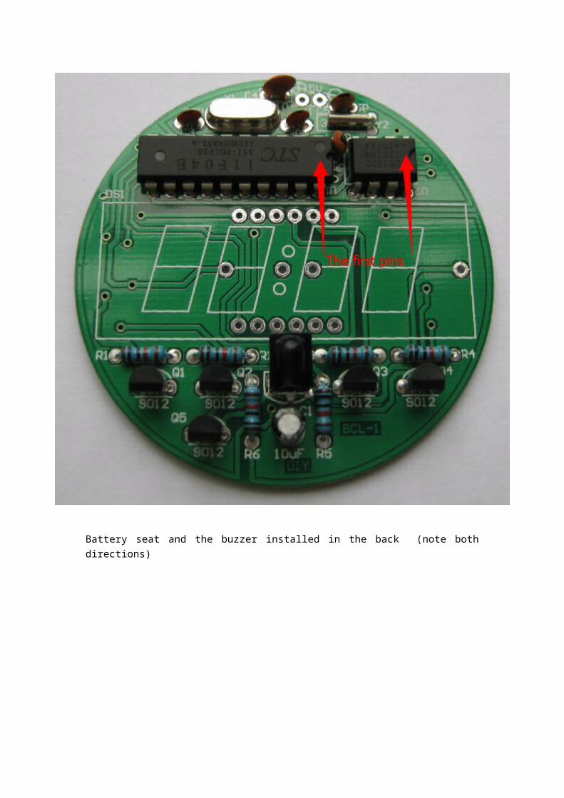
Battery seat and the buzzer installed in the back (note both directions)
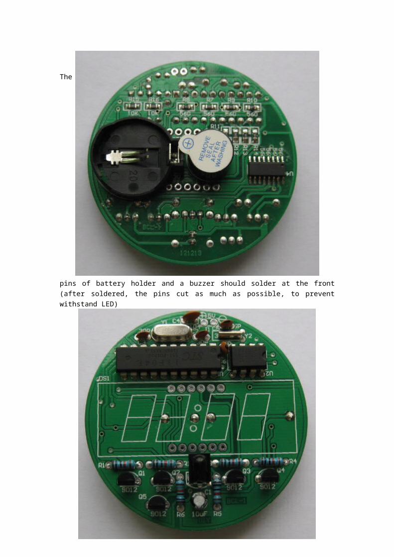
The pins of battery holder and a buzzer should solder at the front (after soldered, the pins cut as much as possible, to prevent withstand LED)
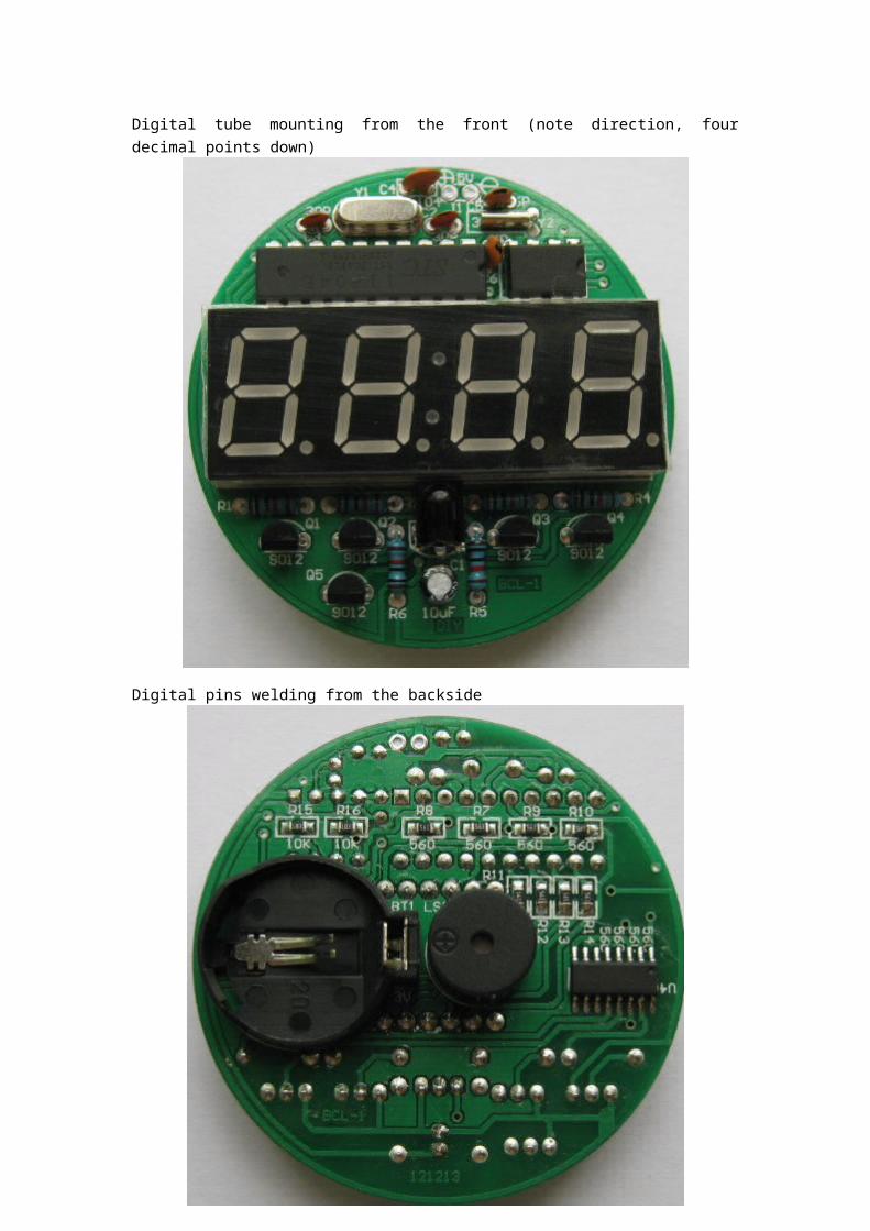
Digital tube mounting from the front (note direction, four decimal points down)
Digital pins welding from the backside
Finish
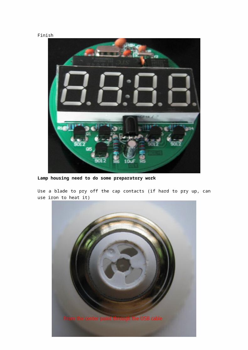
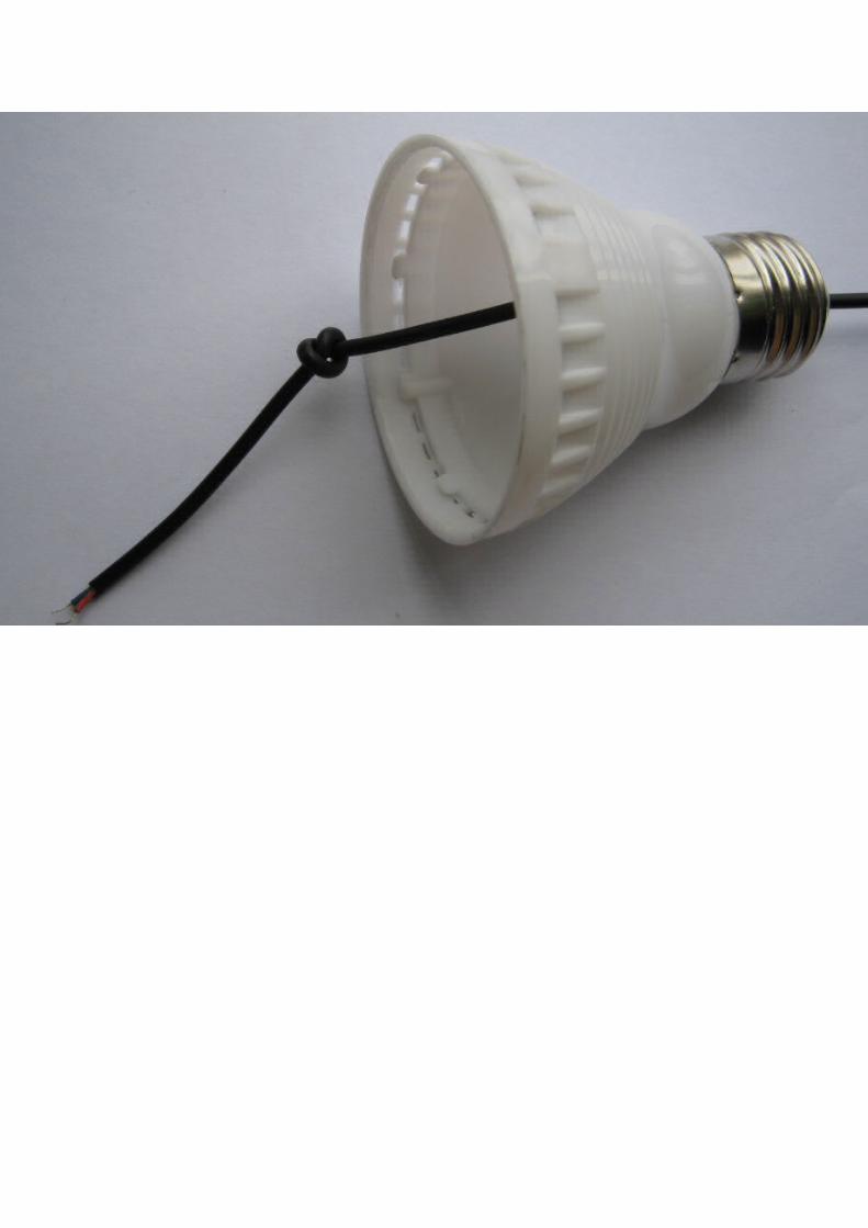
Lamp housing need to do some preparatory work
Use a blade to pry off the cap contacts (if hard to pry up, can use iron to heat it)
Raised portions for fixing the lamp cover with a razor blade to cut low, otherwise shade once installed it is difficult to take down. The purpose of this is to facilitate repair or replace that battery.
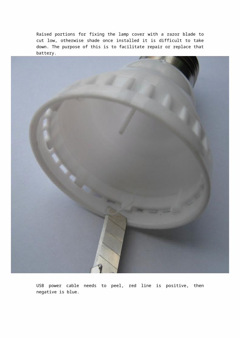
USB power cable needs to peel, red line is positive, then negative is blue.
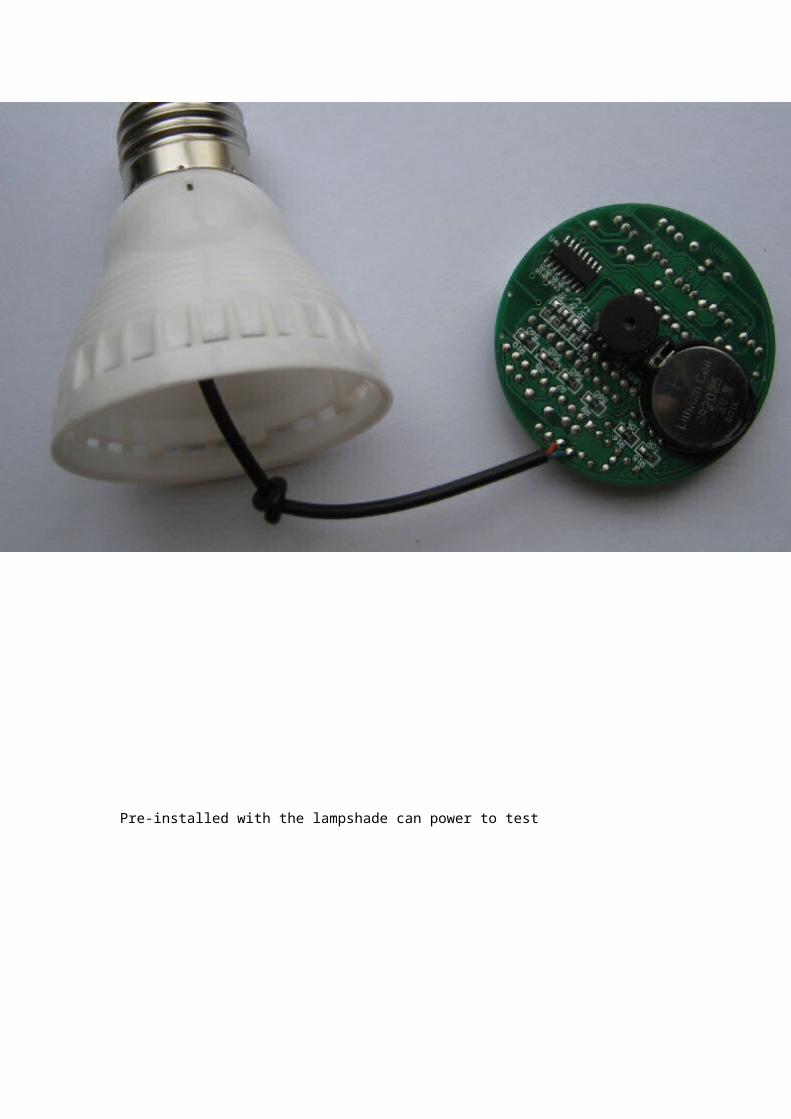
Pre-installed with the lampshade can power to test