Physics and Technology of Transparent Ceramic Armor… · Andreas Krell, Thomas Hutzler, Jens...
28
Andreas Krell, Thomas Hutzler, Jens Klimke Fraunhofer Institute of Ceramic Technologies and Sintered Materials Winterbergstrasse 28, 01277 Dresden, Germany [email protected] ABSTRACT Sintered sub-μm alumina (α 2O3) is the hardest transparent armor. However, its trigonal structure gives -Al rise to a strong thickness effect that makes thicker components translucent. Cubic ceramics (no birefrin- gence!), on the other hand, are less hard but may exhibit an improved transmission. Known cubic armor ceramics are manufactured in a way resulting in coarse microstructures with low hardness. Therefore, a cubic sub-μm spinel was developed here that associates a high hardness > 14 GPa with an in-line transmission approaching the theoretical limit - with the consequence that the thickness effect becomes very small, and transparent components can be manufactured with several mm thickness without loss of transmissivity. Additionally, weight benefits at high protective strength are expected be- cause the hard components can be designed thinner than using known spinel or AlON grades. 1 INTRODUCTION The central difficulty in the development of transparent armor is that some thickness of the component is imperative for obtaining a high protective strength whereas, on the other hand, light transmission de- creases and specific weight increases with increasing thickness. The final goal is, therefore, a transparent material the high ballistic mass efficiency of which enables the design of thinner windows. This ballistic mass efficiency scales with the hardness of ceramic armor [1]. Sintered Al 2 O 3 with sub-μm grain size is the hardest of all transparent armor (including sapphire). With a maximum mass efficiency that may outperform even (opaque) SiC/B 4 C composites [2] it is one of the most promising candidates for advanced developments. However, the birefringence of the trigonal (rhombohedral) crystallites contributes to light scattering in a way that transmission is subject of a strong thickness effect. On the other hand, birefringence does not apply to cubic ceramics, and a transmission of 80-82 % was re- ported at 1 mm thickness for sintered yttria (Y 2 O 3 ) [3] and for sintered Y-Al and Yb-Al garnets [4]. These are, however, expensive materials. Costs are lower for spinel ceramics (MgO . Al 2 O 3 ) [5][6][7][8][9] and possibly for AlON [10], but often their transmittance is surprisingly low [9][10] and/or ill-defined [5] [6][7][9][10]. Also, known cubic ceramics suffer shortcomings with respect to their protective strength: (i) At equal relative density and grain size they exhibit a lower hardness than Al 2 O 3 . (ii) The hardness is further decreased because of large grain sizes > 5 μm which grow during sintering at high temperatures (used to eliminate last light scattering pores: a high in-line transmission of ~ 60 % at 2 mm thickness was measured with a small aperture of ~ 0.2° just for the coarsest grades of spinel with grain sizes > 150 μm [8]!). Therefore, known spinel and ALON ceramics typically exhibit coarse microstructures with grains > 100 μm and a low hardness (a 2-kg Knoop hardness of 12.1 GPa was reported for an MgO . Al 2 O 3 spinel, 1 and 13.8 GPa for an AlON 2 [11]). It was, therefore, the objective of the present work with sintered alumina ceramics and with ceramics of the cubic system to investigate which (thickness-dependent) transmission can be associated with a mini- mum grain size for enabling a maximum hardness and resulting in a high protective strength. 1 Raytheon Company, Lexington (MA), USA. 2 RCS Technologies, Inc., Research Triangle Park (NC), USA. RTO-MP-AVT-122 14 - 1 UNCLASSIFIED/UNLIMITED UNCLASSIFIED/UNLIMITED Physics and Technology of Transparent Ceramic Armor: Sintered Al 2 O 3 vs Cubic Materials Krell, A.; Hutzler, T.; Klimke, J. (2005) Physics and Technology of Transparent Ceramic Armor: Sintered Al 2 O 3 vs Cubic Materials. In Nanomaterials Technology for Military Vehicle Structural Applications (pp. 14-1 – 14-10). Meeting Proceedings RTO-MP-AVT-122, Paper 14. Neuilly-sur-Seine, France: RTO. Available from: http://www.rto.nato.int/abstracts.asp.
Transcript of Physics and Technology of Transparent Ceramic Armor… · Andreas Krell, Thomas Hutzler, Jens...
Andreas Krell, Thomas Hutzler, Jens Klimke Fraunhofer Institute of Ceramic Technologies and Sintered Materials
Winterbergstrasse 28, 01277 Dresden, Germany
ABSTRACT Sintered sub-µm alumina (α 2O3) is the hardest transparent armor. However, its trigonal structure gives -Alrise to a strong thickness effect that makes thicker components translucent. Cubic ceramics (no birefrin-gence!), on the other hand, are less hard but may exhibit an improved transmission. Known cubic armor ceramics are manufactured in a way resulting in coarse microstructures with low hardness. Therefore, a cubic sub-µm spinel was developed here that associates a high hardness > 14 GPa with an in-line transmission approaching the theoretical limit - with the consequence that the thickness effect becomes very small, and transparent components can be manufactured with several mm thickness without loss of transmissivity. Additionally, weight benefits at high protective strength are expected be-cause the hard components can be designed thinner than using known spinel or AlON grades.
1 INTRODUCTION The central difficulty in the development of transparent armor is that some thickness of the component is imperative for obtaining a high protective strength whereas, on the other hand, light transmission de-creases and specific weight increases with increasing thickness. The final goal is, therefore, a transparent material the high ballistic mass efficiency of which enables the design of thinner windows. This ballistic mass efficiency scales with the hardness of ceramic armor [1]. Sintered Al2O3 with sub-µm grain size is the hardest of all transparent armor (including sapphire). With a maximum mass efficiency that may outperform even (opaque) SiC/B4C composites [2] it is one of the most promising candidates for advanced developments. However, the birefringence of the trigonal (rhombohedral) crystallites contributes to light scattering in a way that transmission is subject of a strong thickness effect. On the other hand, birefringence does not apply to cubic ceramics, and a transmission of 80-82 % was re-ported at 1 mm thickness for sintered yttria (Y2O3) [3] and for sintered Y-Al and Yb-Al garnets [4]. These are, however, expensive materials. Costs are lower for spinel ceramics (MgO.Al2O3) [5][6][7][8][9] and possibly for AlON [10], but often their transmittance is surprisingly low [9][10] and/or ill-defined [5] [6][7][9][10]. Also, known cubic ceramics suffer shortcomings with respect to their protective strength: (i) At equal relative density and grain size they exhibit a lower hardness than Al2O3. (ii) The hardness is further decreased because of large grain sizes > 5 µm which grow during sintering at
high temperatures (used to eliminate last light scattering pores: a high in-line transmission of ~ 60 % at 2 mm thickness was measured with a small aperture of ~ 0.2° just for the coarsest grades of spinel with grain sizes > 150 µm [8]!). Therefore, known spinel and ALON ceramics typically exhibit coarse microstructures with grains > 100 µm and a low hardness (a 2-kg Knoop hardness of 12.1 GPa was reported for an MgO.Al2O3 spinel,1 and 13.8 GPa for an AlON2 [11]).
It was, therefore, the objective of the present work with sintered alumina ceramics and with ceramics of the cubic system to investigate which (thickness-dependent) transmission can be associated with a mini-mum grain size for enabling a maximum hardness and resulting in a high protective strength.
1 Raytheon Company, Lexington (MA), USA. 2 RCS Technologies, Inc., Research Triangle Park (NC), USA.
RTO-MP-AVT-122 14 - 1
UNCLASSIFIED/UNLIMITED
UNCLASSIFIED/UNLIMITED
Physics and Technology of Transparent Ceramic Armor: Sintered Al2O3 vs Cubic Materials
Krell, A.; Hutzler, T.; Klimke, J. (2005) Physics and Technology of Transparent Ceramic Armor: Sintered Al2O3 vs Cubic Materials. In Nanomaterials Technology for Military Vehicle Structural Applications (pp. 14-1 – 14-10). Meeting Proceedings RTO-MP-AVT-122, Paper 14. Neuilly-sur-Seine, France: RTO. Available from: http://www.rto.nato.int/abstracts.asp.
Report Documentation Page Form ApprovedOMB No. 0704-0188
Public reporting burden for the collection of information is estimated to average 1 hour per response, including the time for reviewing instructions, searching existing data sources, gathering andmaintaining the data needed, and completing and reviewing the collection of information. Send comments regarding this burden estimate or any other aspect of this collection of information,including suggestions for reducing this burden, to Washington Headquarters Services, Directorate for Information Operations and Reports, 1215 Jefferson Davis Highway, Suite 1204, ArlingtonVA 22202-4302. Respondents should be aware that notwithstanding any other provision of law, no person shall be subject to a penalty for failing to comply with a collection of information if itdoes not display a currently valid OMB control number.
1. REPORT DATE 01 AUG 2006
2. REPORT TYPE N/A
3. DATES COVERED -
4. TITLE AND SUBTITLE Physics and Technology of Transparent Ceramic Armor: Sintered Al2O3vs Cubic Materials
5a. CONTRACT NUMBER
5b. GRANT NUMBER
5c. PROGRAM ELEMENT NUMBER
6. AUTHOR(S) 5d. PROJECT NUMBER
5e. TASK NUMBER
5f. WORK UNIT NUMBER
7. PERFORMING ORGANIZATION NAME(S) AND ADDRESS(ES) Fraunhofer Institute of Ceramic Technologies and Sintered MaterialsWinterbergstrasse 28, 01277 Dresden, Germany
8. PERFORMING ORGANIZATIONREPORT NUMBER
9. SPONSORING/MONITORING AGENCY NAME(S) AND ADDRESS(ES) 10. SPONSOR/MONITOR’S ACRONYM(S)
11. SPONSOR/MONITOR’S REPORT NUMBER(S)
12. DISTRIBUTION/AVAILABILITY STATEMENT Approved for public release, distribution unlimited
13. SUPPLEMENTARY NOTES See also ADM202077, RTO-MP-AVT-122. Nanomaterials Technology for Military Vehicle StructuralApplications (La technologie des nanomateriaux au service des applications structurelles des vehiculesmilitaires)., The original document contains color images.
14. ABSTRACT
15. SUBJECT TERMS
16. SECURITY CLASSIFICATION OF: 17. LIMITATION OF ABSTRACT
UU
18. NUMBEROF PAGES
27
19a. NAME OFRESPONSIBLE PERSON
a. REPORT unclassified
b. ABSTRACT unclassified
c. THIS PAGE unclassified
Standard Form 298 (Rev. 8-98) Prescribed by ANSI Std Z39-18
2 PHYSICAL BACKGROUND
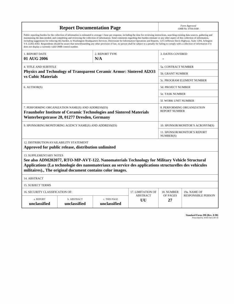
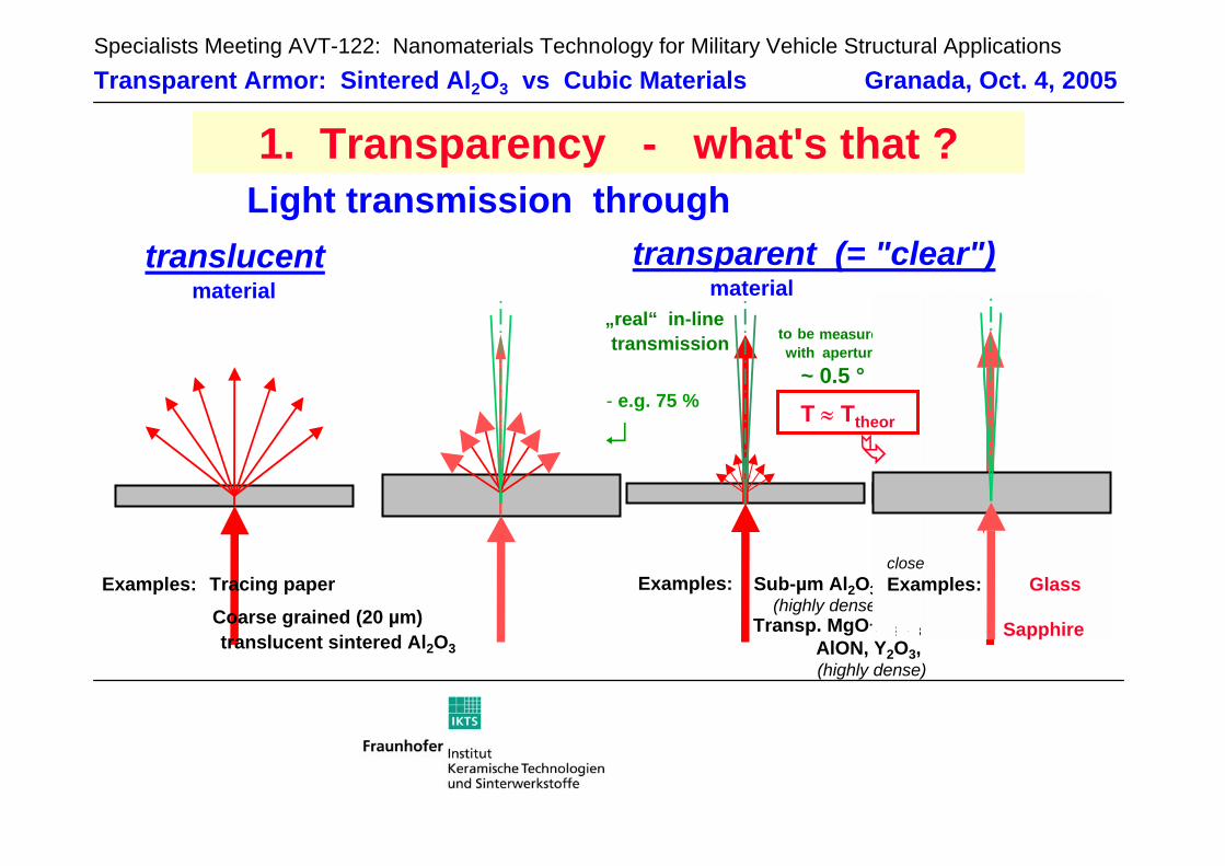
2.1 Light transmission through polycrystalline ceramics, implications for nano-technology Fig. 1 reviews the processes of light transmission through non-cubic polycrystalline ceramics assuming that the single crystalline material is highly transparent (= low absorption as e.g. in the case of single crys-talline corundum [sapphire, α-Al2O3]). Whereas the total forward transmission includes contributions from both scattered and unscattered light, only the latter enables optical imaging. For this in-line transmis-sion of light two contributions to scattering losses have to be considered: 1. In all translucent or transparent materials (independent of their crystal structure) diffuse scattering
takes place at the sites of second phases with different refractive index (pores, particles of additives or impurities).
2. In microstructures of optically non-isotropic crystals birefringence splits the beam on each cross-over from one grain to the next. This second contribution to scattering losses of the in-line transmission ap-plies, therefore, to non-cubic ceramics only (e.g. Al2O3).
Incident light Reflected light(7-8 % each Al2O3 surface)
Transmitted light (in-line direction)
Scattering at
grain boundaries(Al2O3: n = 1.760 / 1.768)
Diffuse scattering atpores
Figure 1: Light transmission through polycrystalline alumina (Al2O3; example: coarse [translucent] grade).
The influences of porosity and grain sizes have been evaluated recently [12] and are given by Fig. 2 to-gether with experimental data [13]. Obviously, in all (non-cubic or cubic) ceramics real transparency (i.e. a high in-line transmission) needs the elimination of last hundredths (!) of percents of porosity, and this is the reason why common "high-tech" alumina ceramics which are considered "dense" at a relative density of e.g. 99.7 % are opaque (white when produced with a high purity and sintered in air).
0.0 0.1 0.2 0.3 0.4 0.50
20
40
60
80
100
in-line
total forward
pore size = 100 nmd = 0.8 mmλo = 600 nm
Tran
smis
sio
n (
%)
Porosity (%) (a) (b) Figure 2: Influences of porosity and grain size on the light transmission through Al2O3
The porosity influence (a) was calculated for a homogeneous material, and the calculated grain size effect (b) refers to zero porosity [12]. Lower experimental values at sub-µm grain sizes [13] represent small [not measurable!] porosities < 0.1 %.
As a consequence of the extreme difficulty of eliminating last hundredths of porosity percents, most ap-proaches to translucent ceramics use high sintering temperatures associated with extended grain growth. As a result, coarse products like the (non-cubic) Al2O3 of Fig. 1 (sintered at 1800-1900 °C) are obtained
0
10
20
30
40
50
60
70
80
90
100
0 1 2 3 4 5 6 7
Experimental data
Calculated model ( ref. 6)
Grain size (µm)
Rea
l in-
line
tran
smis
sion
(%
)
influ
ence
of r
esid
ual p
oros
ity
Physics and Technology of Transparent Ceramic Armor: Sintered Al2O3 vs Cubic Materials
14 - 2 RTO-MP-AVT-122
UNCLASSIFIED/UNLIMITED
UNCLASSIFIED/UNLIMITED
with a porosity that may be sufficiently low for transparency but which, in fact, are translucent only with an in-line transmission < 10 % because of birefringent scattering losses (cp. the grain size effect in Fig. 2b). On the other extreme, still larger grains > 500 µm are needed to approach the high transmission of single crystals - even grain sizes of 200 µm increase the transmission to only 15-20 % [14]. Therefore, the development of transparent sintered corundum ceramics with a high in-line transmission needs a minimum of birefringent contributions to scattering (Fig. 1). For this end, the birefringent crystal-lites of the ceramic have to be so small that they are not “seen” by the light. This occurs at small grain sizes comparable with or smaller than the wavelength of the light (Fig. 2b).
It has been suggested that such most fine-grained microstructures could be obtained preferentially by us-ing the most fine-grained nanopowders which, because of their strong surface curvature, exhibit highest surface diffusion and evaporation/condensation activities promoting densification. However, increased diffusion on strongly curved surfaces is a feature of the individual particle only, whereas a "densification activity” is governed the interaction of a multitude of particles. Unfortunately, the high surface curvature of nanoparticles is also a strong driving force for agglomeration, and the resulting inhomogeneous mutual coordination of particles and of the pore distribution considerably retards densification [15]. Therefore, only an extremely homogeneous particle coordination in the shaped “green” (still not sintered) bodies can provide the extremely high sintering density (imperative for transparency) at lowest sintering temperatures (preventing grain growth), and detailed investigations have shown that it is not the most fine-grained nanopowder which associates the finest sintered microstructure with the highest density. Instead, it is the state of the development of defect-free powder processing technologies which determines an op-timum powder particle size for a successful production of nanoceramics with highest density [16][17].
Because of the absence of birefringent scattering the grain size effect does not apply to cubic ceramics, and high-temperature sintering might be expected to give clear transparent microstructures even when the grain sizes grow large. Examples of coarse (grain size > 150 µm) and highly transparent spinel are really known [8], but beyond the general deficit of their low hardness there is also an observation of often sur-prisingly low transmission characteristics of such coarse cubic ceramics (e.g. AlON [10], spinel [9][18], Y-Al garnet [19], Y2O3 [20]). The reason of the latter issue is that extended grain growth frequently gives rise to the inclusion of pores into the growing crystals - with the result of a significant residual porosity which is hard to eliminate. Therefore, high temperatures are not a generally valid means to obtain least porosity (and high transpar-ency), and this conclusion provides the motivation for introducing the nanotechnological experiences of the alumina line [13][17] into the development of new spinel as to be outlined below (§3).
2.2 Resulting measurement needs for a quantitative characterization of transparency In §2.1 a small grain size was claimed as an essential for obtaining transparent non-cubic sintered ceram-ics. From a physical point of view this same feature also means: - In non-cubic ceramics the benefit of small grain sizes is identical with the statement that at fixed grain
size the transmission will increase with the wavelength. - This grain size related dependence on the wavelength will not apply for dense cubic sintered ceramics
(or for single crystals).1 Additionally, the wavelength is of course important for understanding absorption (e.g. in the far IR or UV ranges). Therefore, any experimental transmission result needs a given reference to the wavelength.
Similarly important is the geometric characterization of the measuring equipment. Obviously, optical im-aging through windows or lenses needs the transmission of defined beams. Therefore, only the in-line transmission of unscattered light provides the right quantitative characterization of transparency (different
1 Note, however, that the wavelength may become important here as well as in non-cubic ceramics if the size of residual pores
interferes with the wavelength (cp. [12] for the effect of pore sizes).
Physics and Technology of Transparent Ceramic Armor: Sintered Al2O3 vs Cubic Materials
RTO-MP-AVT-122 14 - 3
UNCLASSIFIED/UNLIMITED
UNCLASSIFIED/UNLIMITED
from translucency [the degree of which is given by the total forward transmission including contributions from both scattered and unscattered light]). Unfortunately, two difficulties arise: - A strict "in-line" measurement is difficult since it would require a zero opening aperture1 between
specimen surface and detector, and this would give an intensity record close to zero. - On the other hand, many "in-line" or "linear" transmission results in the literature are, in fact, meaning-
less because they are obtained with standard photospectrometers with large apertures (3°-5°).2
Therefore, transmission data published without a reference to the used aperture are invalid for comparison. Without a common standard, an aperture of about 0.5° was repeatedly used in the past years to give, on the one hand, a recorded intensity which is sufficiently high for the requested accuracy of the measurement while approaching, on the other hand, the desired condition of a "real" in-line transmission [12][13][21].
Of course, images of "clearly seen" printed matter under an overlaying thin plate of "transparent" armor do not give the least indication of the real character of light transmission: in this kind of presentation both in-line and scattered transmission contribute to the seen result, and identically "clear" images are obtained with transparent as also with only translucent materials. It is, therefore, impossible, to distinguish transparent from poorly translucent materials by such images.
Another influence is the surface state which should be carefully polished to avoid diffuse reflection losses.
When comparing different materials as Al2O3, Y2O3 and others, the recorded transmission is also affected by the different reflection losses on the two surfaces of a window.3 However, the resulting theoretical (maximum) transmission Tth is similar for all of the ceramics addressed here (at small influence of wave-length): 85.8 % for Al2O3, 86.9 % for MgO.Al2O3 spinel, 85.3 % for Y2O3, 84.1 % for an Al-Y garnet.
2.3 Relative transmission and thickness effect With wavelength, measuring aperture and surface state, a fourth important parameter that influences the results of transmission measurements is the specimen thickness. The existence of this effect is trivial but is addressed here separately because of an important technical consequence for applications: Because of the thickness effect, only materials with a real in-line transmission4 close to the theoretical maximum Tth can be enlarged in thickness without a greater loss of transmission. Or vice versa: all components with a real in-line transmission T < Tth suffer a loss (Tth - T), and this loss will increase with the thickness of such components.
It is, therefore, important to understand, that e.g. a 1 mm thick polycrystalline Al2O3 window with an (ex-tremely high) real in-line transmission of 70 % (measured e.g. at 640 nm wavelength) may well give the impression of an apparently "fully" transparent component. Nevertheless, there are still about 16 % of scattering loss (Tth ≈ 86 %), this loss will increase with the thickness, and at a thickness of e.g. about 5 mm this same material will exhibit a real in-line transmission < 30 % and will become translucent. Thus, as far as a measured real in-line transmission is < Tth, the characterization as transparent or translu-cent is not a real materials property but depends on the thickness.
An important consequence for conclusions about chances of future products is: any statement like "real in-line transmission < Tth" is identical with the fact of a significant thickness ef-fect which makes the manufacture of transparent windows impossible beyond some critical thickness.
1 Aperture = half of total opening angle. 2 Note that doubling the aperture from e.g. 2.5° to 5 ° gives a 4fold area and may, therefore, increase the "measured" "in-line"
transmission up to this factor of 4. 3 Reflection amounts {(n-1)/(n+1)}2 for one surface; n - refractive index. 4 To be measured with a sample which should not be too thin.
Physics and Technology of Transparent Ceramic Armor: Sintered Al2O3 vs Cubic Materials
14 - 4 RTO-MP-AVT-122
UNCLASSIFIED/UNLIMITED
UNCLASSIFIED/UNLIMITED
3 EXPERIMENTS
3.1 Materials preparation Sintered Al2O3 windows of 100 x 100 mm2 size where manufactured from a commercial powder (purity 99.995 %, particle size 150-200 nm, specific surface 14 m2/g) by a defect-avoiding gelcasting process fol-lowed by pre-sintering and hot-isostatic post-densification (HIP) as published previously [13] and reported on a foregoing meeting [17]. All alumina samples were doped with 0.03 wt.-% MgO.
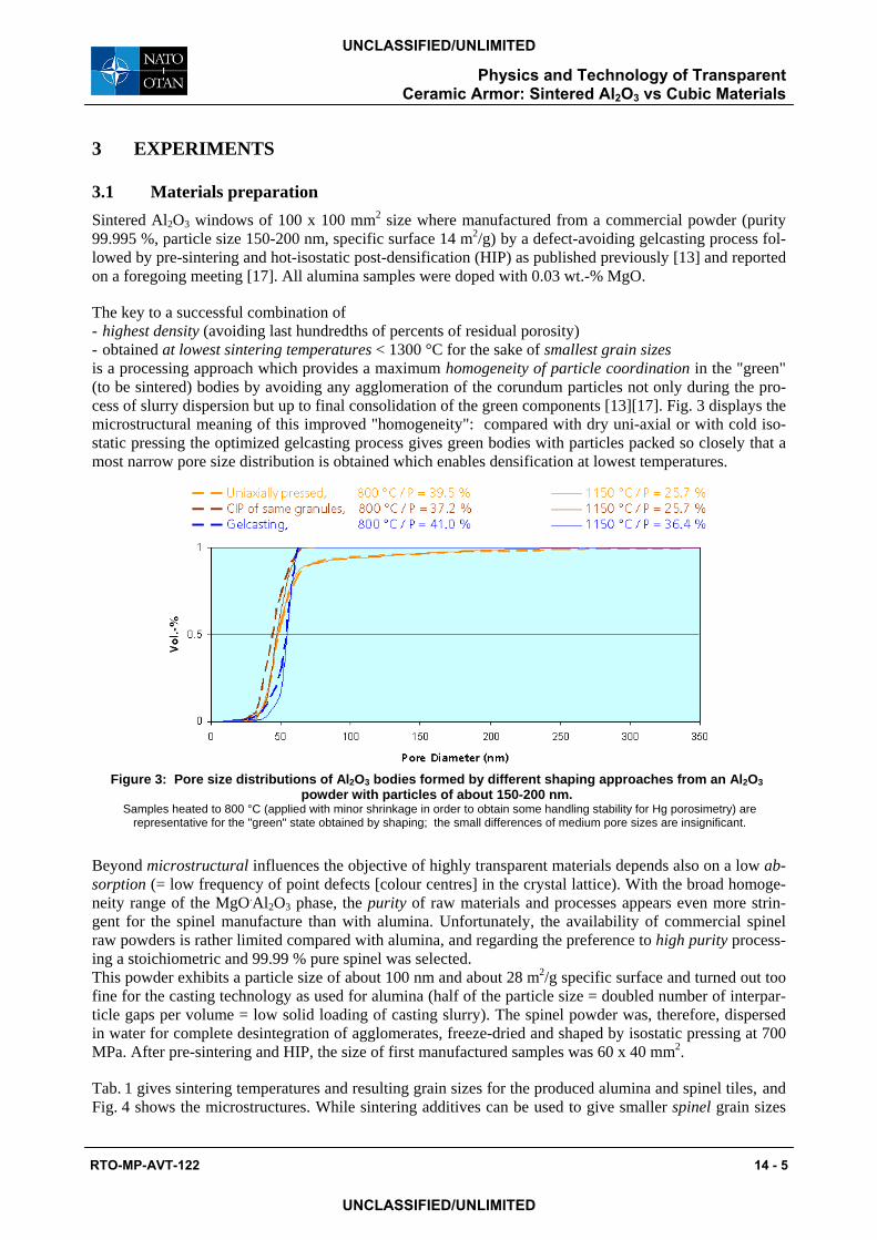
The key to a successful combination of - highest density (avoiding last hundredths of percents of residual porosity) - obtained at lowest sintering temperatures < 1300 °C for the sake of smallest grain sizes is a processing approach which provides a maximum homogeneity of particle coordination in the "green" (to be sintered) bodies by avoiding any agglomeration of the corundum particles not only during the pro-cess of slurry dispersion but up to final consolidation of the green components [13][17]. Fig. 3 displays the microstructural meaning of this improved "homogeneity": compared with dry uni-axial or with cold iso-static pressing the optimized gelcasting process gives green bodies with particles packed so closely that a most narrow pore size distribution is obtained which enables densification at lowest temperatures.
Figure 3: Pore size distributions of Al2O3 bodies formed by different shaping approaches from an Al2O3
powder with particles of about 150-200 nm. Samples heated to 800 °C (applied with minor shrinkage in order to obtain some handling stability for Hg porosimetry) are
representative for the "green" state obtained by shaping; the small differences of medium pore sizes are insignificant.
Beyond microstructural influences the objective of highly transparent materials depends also on a low ab-sorption (= low frequency of point defects [colour centres] in the crystal lattice). With the broad homoge-neity range of the MgO.Al2O3 phase, the purity of raw materials and processes appears even more strin-gent for the spinel manufacture than with alumina. Unfortunately, the availability of commercial spinel raw powders is rather limited compared with alumina, and regarding the preference to high purity process-ing a stoichiometric and 99.99 % pure spinel was selected. This powder exhibits a particle size of about 100 nm and about 28 m2/g specific surface and turned out too fine for the casting technology as used for alumina (half of the particle size = doubled number of interpar-ticle gaps per volume = low solid loading of casting slurry). The spinel powder was, therefore, dispersed in water for complete desintegration of agglomerates, freeze-dried and shaped by isostatic pressing at 700 MPa. After pre-sintering and HIP, the size of first manufactured samples was 60 x 40 mm2.
Tab. 1 gives sintering temperatures and resulting grain sizes for the produced alumina and spinel tiles, and Fig. 4 shows the microstructures. While sintering additives can be used to give smaller spinel grain sizes
Physics and Technology of Transparent Ceramic Armor: Sintered Al2O3 vs Cubic Materials
RTO-MP-AVT-122 14 - 5
UNCLASSIFIED/UNLIMITED
UNCLASSIFIED/UNLIMITED
by means of lower sintering, a small Zr additive significantly increases the sintering temperature of alu-mina resulting, nevertheless, in a smaller grain size which improves the transparency [13].
Table 1: Sintering conditions and resulting grain sizes at relative density > 99.9 %.
Transparent ceramics Powder: Particle size - Spec. surface
Shaping approach
Green density
Sintering + HIP temperatures
Grain size (sintered body)
Sintered corundum (Al2O3) 150...200 nm - 14 m2/g Gelcasting ~ 59 % 1255 °C + 1200 °C 1310 °C + 1280 °C
0.6 µm 0.5 µm #
Sintered spinel (MgO.Al2O3)
~ 100 nm - 28 m2/g Isostatic pressing 57 - 58 % 1455 °C + 1420 °C 1270 °C + 1260 °C
0.8 µm 0.5 µm *
# doped with ~ 0.2 wt-% ZrO2 (additionally to + 0.03 % MgO) * reduced manufacturing temperatures by sintering additive
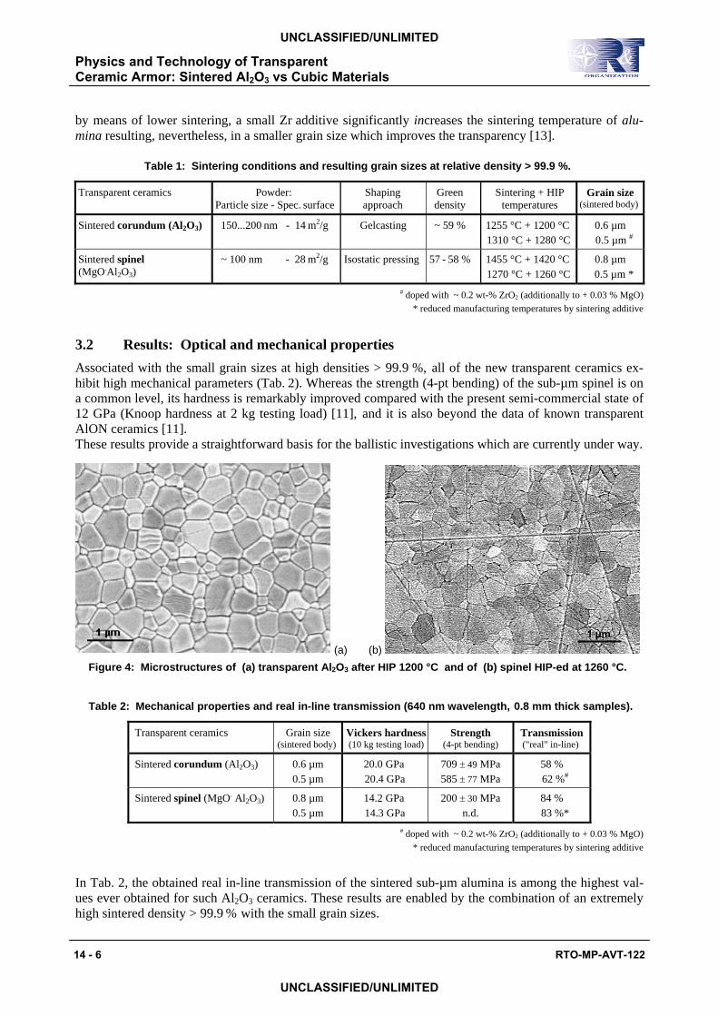
3.2 Results: Optical and mechanical properties Associated with the small grain sizes at high densities > 99.9 %, all of the new transparent ceramics ex-hibit high mechanical parameters (Tab. 2). Whereas the strength (4-pt bending) of the sub-µm spinel is on a common level, its hardness is remarkably improved compared with the present semi-commercial state of 12 GPa (Knoop hardness at 2 kg testing load) [11], and it is also beyond the data of known transparent AlON ceramics [11]. These results provide a straightforward basis for the ballistic investigations which are currently under way.
(a) (b) Figure 4: Microstructures of (a) transparent Al2O3 after HIP 1200 °C and of (b) spinel HIP-ed at 1260 °C.
Table 2: Mechanical properties and real in-line transmission (640 nm wavelength, 0.8 mm thick samples).
Transparent ceramics Grain size (sintered body)
Vickers hardness(10 kg testing load)
Strength (4-pt bending)
Transmission ("real" in-line)
Sintered corundum (Al2O3) 0.6 µm 0.5 µm
20.0 GPa 20.4 GPa
709 ± 49 MPa 585 ± 77 MPa
58 % 62 %#
Sintered spinel (MgO. Al2O3) 0.8 µm 0.5 µm
14.2 GPa 14.3 GPa
200 ± 30 MPa n.d.
84 % 83 %*
# doped with ~ 0.2 wt-% ZrO2 (additionally to + 0.03 % MgO) * reduced manufacturing temperatures by sintering additive
In Tab. 2, the obtained real in-line transmission of the sintered sub-µm alumina is among the highest val-ues ever obtained for such Al2O3 ceramics. These results are enabled by the combination of an extremely high sintered density > 99.9 % with the small grain sizes.
1 µm
Physics and Technology of Transparent Ceramic Armor: Sintered Al2O3 vs Cubic Materials
14 - 6 RTO-MP-AVT-122
UNCLASSIFIED/UNLIMITED
UNCLASSIFIED/UNLIMITED
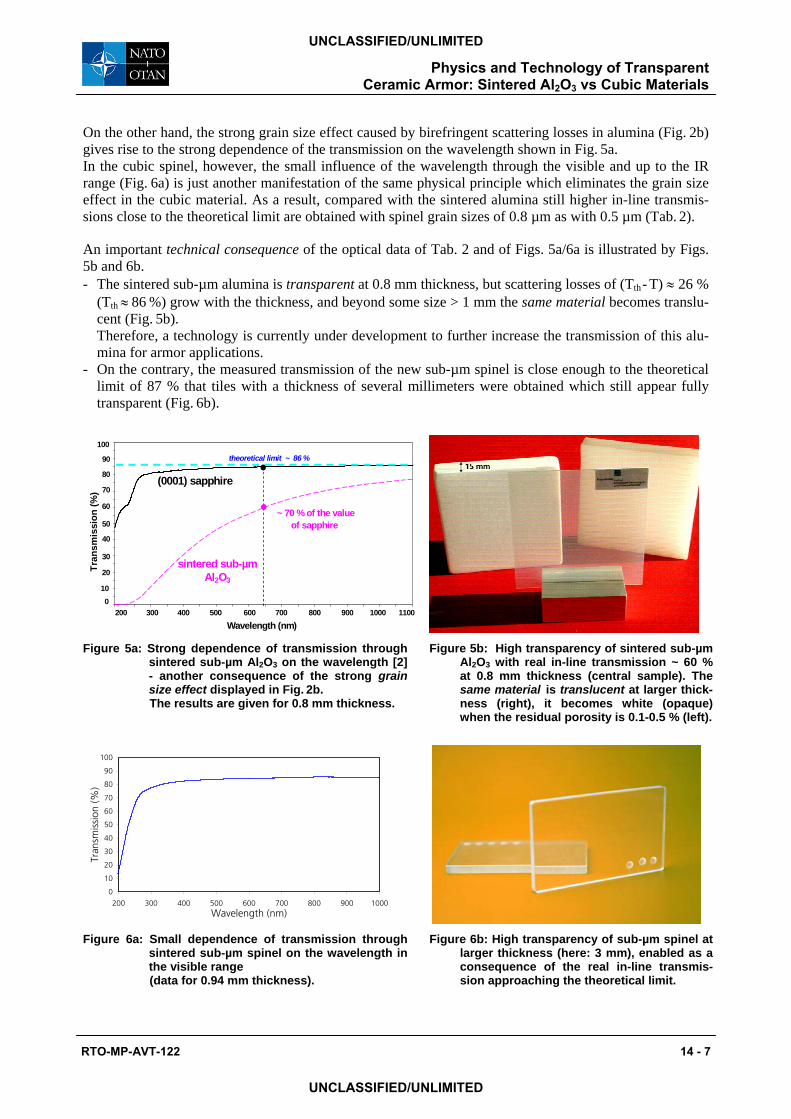
On the other hand, the strong grain size effect caused by birefringent scattering losses in alumina (Fig. 2b) gives rise to the strong dependence of the transmission on the wavelength shown in Fig. 5a. In the cubic spinel, however, the small influence of the wavelength through the visible and up to the IR range (Fig. 6a) is just another manifestation of the same physical principle which eliminates the grain size effect in the cubic material. As a result, compared with the sintered alumina still higher in-line transmis-sions close to the theoretical limit are obtained with spinel grain sizes of 0.8 µm as with 0.5 µm (Tab. 2).
An important technical consequence of the optical data of Tab. 2 and of Figs. 5a/6a is illustrated by Figs. 5b and 6b. - The sintered sub-µm alumina is transparent at 0.8 mm thickness, but scattering losses of (Tth - T) ≈ 26 %
(Tth ≈ 86 %) grow with the thickness, and beyond some size > 1 mm the same material becomes translu-cent (Fig. 5b).
Therefore, a technology is currently under development to further increase the transmission of this alu-mina for armor applications.
- On the contrary, the measured transmission of the new sub-µm spinel is close enough to the theoretical limit of 87 % that tiles with a thickness of several millimeters were obtained which still appear fully transparent (Fig. 6b).
100
Wavelength (nm)
Tran
smis
sion
(%)
90
300 200 1100 600
sintered sub-µm Al2O3
(0001) sapphire
theoretical limit ~ 86 %
400 500 700 800 900 1000
~ 70 % of the valueof sapphire
80
70
60
50
40
30
20
10 0
Figure 5a: Strong dependence of transmission through
sintered sub-µm Al2O3 on the wavelength [2] - another consequence of the strong grain size effect displayed in Fig. 2b.
The results are given for 0.8 mm thickness.
Figure 5b: High transparency of sintered sub-µm Al2O3 with real in-line transmission ~ 60 % at 0.8 mm thickness (central sample). The same material is translucent at larger thick-ness (right), it becomes white (opaque) when the residual porosity is 0.1-0.5 % (left).
Figure 6a: Small dependence of transmission through
sintered sub-µm spinel on the wavelength in the visible range
(data for 0.94 mm thickness).
Figure 6b: High transparency of sub-µm spinel at larger thickness (here: 3 mm), enabled as a consequence of the real in-line transmis-sion approaching the theoretical limit.
0
10
20
30
40
50
60
70
80
90
100
200 300 400 500 600 700 800 900 1000Wavelength (nm)
Tran
smis
sion
(%)
Physics and Technology of Transparent Ceramic Armor: Sintered Al2O3 vs Cubic Materials
RTO-MP-AVT-122 14 - 7
UNCLASSIFIED/UNLIMITED
UNCLASSIFIED/UNLIMITED
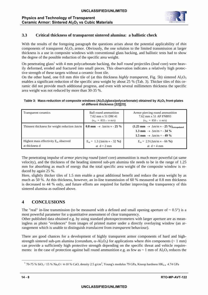
3.3 Critical thickness of transparent sintered alumina: a ballistic check
With the results of the foregoing paragraph the questions arises about the potential applicability of thin components of transparent Al2O3 armor. Obviously, the one solution to the limited transmission at larger thickness is a use in composite windows with conventional glass backing, and ballistic tests had to show the degree of the possible reduction of the specific area weight.
On penetrating glass1 with 4 mm polycarbonate backing, the ball round projectiles (lead core) were heav-ily deformed, eroded and fractured into small pieces. This observation indicates a relatively high protec-tive strength of these targets without a ceramic front tile. On the other hand, one 0.8 mm thin tile of (at this thickness highly transparent, Fig. 5b) sintered Al2O3 enables a significant reduction of the specific area weight by about 25 % (Tab. 3). Thicker tiles of this ce-ramic did not provide much additional progress, and even with several millimeters thickness the specific area weight was not reduced by more than 30-35 %.
Table 3: Mass-reduction of composite windows (Al2O3/glass/polycarbonate) obtained by Al2O3 front-plates of different thickness [22][23].
Transparent ceramics Ball round ammunition 7.62 mm x 51 DM 41
(vhit = 833 ± 10 m/s)
Armor piercing round ammunition 7.62 mm x 51 AP FNB93
(vhit = 850 ± 15 m/s)
Thinnest thickness for weight reduction ∆m/m 0.8 mm → ∆m/m ≈ - 25 % (1.25 mm → ∆m/m ≈ - 25 %)extrapolated 1.3 mm → ∆m/m = - 34 % 1.5 mm → ∆m/m = - 49 %
Highest mass effectivity Em observed at thickness d
Em = 1.3 (∆m/m ≈ - 32 %) at d = 2 mm
Em = 2.9 (∆m/m ≈ - 66 %) at d = 4 mm
The penetrating impulse of armor piercing round (steel core) ammunition is much more powerful (at same velocity), and the thickness of the heading sintered sub-µm alumina tile needs to be in the range of 1.25 mm for absorbing as much of energy that the total specific area weight of the composite window is re-duced by again 25 %. Here, slightly thicker tiles of 1.5 mm enable a great additional benefit and reduce the area weight by as much as 50 %. At this thickness, however, an in-line transmission of 60 % measured at 0.8 mm thickness is decreased to 44 % only, and future efforts are required for further improving the transparency of this sintered alumina as outlined above.
4 CONCLUSIONS
The "real" in-line transmission (to be measured with a defined and small opening aperture of ~ 0.5°) is a most powerful parameter for a quantitative assessment of clear transparency. Other published data obtained e.g. by using standard photospectrometers with larger aperture are as mean-ingless as photo "evidences" from images of printed matter under a directly overlaying window (an ar-rangement which is unable to distinguish translucent from transparent behaviour).
There are good chances for a development of highly transparent armor components of hard and high-strength sintered sub-µm alumina (corundum, α-Al2O3) for applications where thin components (~ 1 mm) can provide a sufficiently high protective strength depending on the specific threat and vehicle require-ments: in the case of protection against ball round ammunition e.g. as few as ~ 1 mm of Al2O3 reduces the
1 70-75 % SiO2 / 15 % Na2O / 4-10 % CaO, density 2.5 g/cm3, Young's modulus 79 GPa, Knoop hardness HK0.4 4.74 GPa
Physics and Technology of Transparent Ceramic Armor: Sintered Al2O3 vs Cubic Materials
14 - 8 RTO-MP-AVT-122
UNCLASSIFIED/UNLIMITED
UNCLASSIFIED/UNLIMITED
specific area weight of a composite alumina/glass/polycarbonate window by about 25-30 % compared with standard glass/polycarbonate. Research activities are, therefore, under way to further improve the transparency of these transparent grades of sintered alumina.
For thicker components, however, birefringent scattering losses turn the sintered Al2O3 translucent even if the grain sizes are < 0.5 µm. As an alternative, cubic polycrystalline ceramics like spinel (MgO.Al2O3) have been known for many years to exhibit high transmission properties independent of the grain sizes but are available with coarse microstructures and a resulting low hardness only [11]. Therefore, sintered spinel grades with a real in-line transmission close to the theoretical maximum were developed here for a first time with average grain sizes of as small as 0.5 µm enabling a high macro-hardness of 14-15 GPa as an important prerequisite of a high protective strength. First ballistic tests with these new grades of transparent spinel are currently under way.
ACKNOWLEDGEMENT This investigation was partly supported by the German Bundeswehr under contract E/E91S/4A299/3F034.
REFERENCES
[1] A. Krell, E. Strassburger, "High-purity submicron Al2O3 armor ceramics: Design, manufacture, and ballistic performance", Ceram. Trans. 134 (2002), 463-471 (= J. McCauley, A. Rajendran. W. Gooch, S. Bless, S. Wax, A. Crowson (eds.), Ceramic Armor Materials by Design, Proc. PAC RIM IV / Ceramic Armor Symposium, Wailea, Maui (HI) 4-8 Nov. 2001), The American Ceramic Society, Westerville (OH), 2002.
[2] A. Krell, G. Baur, C. Dähne, "Transparent sintered sub-µm Al2O3 with IR transmissivity equal to sapphire", pp. 100-207 in: R.W. Tustison (ed.), Window and Dome Technologies VIII, Proceedings of SPIE conference (Orlando, FL/USA, April 22-23, 2003), Vol. 5078, Washington, 2003.
[3] Y. Hideki, Y. Takagimi, "Translucent rare earth oxide sintered article and method for production thereof", US Patent Application 2003/0183991 A1, Oct. 2, 2003.
[4] T. Yanagitani, S. Imagawa, H. Yagi, H. Kubo, "A corrosion resistant ceramic and a production method thereof", European Patent EP - 926 106 B1, July 21, 2004.
[5] G.E. Gazza, S.K. Dutta, "Hot pressing ceramic oxides to transparency by heating in isothermal increments", Patent US - 3,767,745, Oct. 23, 1973.
[6] D.W. Roy, J.L. Hastert, L.E. Coubrough, K.E. Green, A. Trujillo, "Transparent polycrystalline body with high ultraviolet transmittance, process for making, and application thereof", European patent EP - 447 390 B1, Feb. 2, 1994.
[7] M. Shimada, T. Endo, T. Saito, T. Sato, "Fabrication of transparent spinel polycrystalline materials", Mater. Lett. 28 (1996) 4-6, 413-415.
[8] A.F. Dericioglu, Y. Kagawa, "Effect of grain boundary microcracking on the light transmittance of sintered transparent MgAl2O4", J. Europ. Ceram. Soc. 23 (2003) 6, 951-959.
[9] G.R. Villalobos, J.S. Saghera, S.S. Baya, I.D. Agrawal, "Spinel and process for making same", US Patent Application 2004/0266605 A1, Dec. 30, 2004.
[10] D. Agrawal, J. Cheng, R. Roy, "Microwave reactive sintering to fully transparent aluminum oxynitride (AlON) ceramics", Ceram. Trans. 134 (2002), 587-593 (= J. McCauley, A. Rajendran. W. Gooch, S. Bless, S. Wax, A. Crowson (eds.), Ceramic Armor Materials by Design, Proc. PAC RIM IV / Ceramic Armor Symposium, Wailea, Maui (HI) 4-8 Nov. 2001), The American Ceramic Society, Westerville (OH), 2002.
Physics and Technology of Transparent Ceramic Armor: Sintered Al2O3 vs Cubic Materials
RTO-MP-AVT-122 14 - 9
UNCLASSIFIED/UNLIMITED
UNCLASSIFIED/UNLIMITED
[11] J.J. Swab, G.A. Gilde, P.M. Patel, A.A. Wereszscak, J.W. McCauley, "Fracture analysis of transparent armor ceramics", pp. 489-508 in: J.R. Varner, G.D. Quinn (eds.), Fractography of glasses and ceramics IV (Proc. 4th Alfred Conf. on Fractography of Glasses and Ceramics, Alfred, July 9-12, 2000), The American Ceramic Society, Westerville (OH), 2001.
[12] R. Apetz, M.P.B. van Bruggen, "Transparent alumina: A light scattering Model", J. Am. Ceram. Soc. 86 (2003) 3, 480-486.
[13] A. Krell, P. Blank, H. Ma, T. Hutzler, M. van Bruggen, R. Apetz, "Transparent Sintered Corundum with High Hardness and Strength", J. Am. Ceram. Soc. 86 (2003) 1, 12-18.
[14] G.C. Wei, A. Hecker, D.A. Goodman, "Translucent polycrystalline alumina with improved resistance to sodium attack", J. Am. Ceram. Soc. 84 (2001) 12, 2853-2862.
[15] F.F. Lange, "Sinterability of agglomerated powders", J. Am. Ceram. Soc. 67 (1984) 2, 83-89.
[16] A. Krell, P. Blank, H.-W. Ma, T. Hutzler, M. Nebelung, "Processing of High-Density Submicrometer Al2O3 for New Applications", J. Am. Ceram. Soc. 86 (2003) 4, 546-553.
[17] A. Krell, "Transparent sintered sub-µm Al2O3 for armor and IR applications", EUCLID CEPA3 Workshop on Nanomaterials / Session: Novel Smart Materials for Active Structural Applications, Lisbon, Feb. 25, 2004.
[18] K. Shibata, H. Nakamura, "Method of producing a light-transmitting spinel sintered body", European Patent EP - 332 393 B1, June 22, 1994.
[19] G. De With, H.J.A. Van Dijk, "Discharge lamp having a yttrium aluminium garnet discharge envelope", US Patent US - 4,841,195, June 20, 1989.
[20] N. Saito, Sh.-I. Matsuda, T. Ikegami, "Fabrication of transparent yttria ceramics at low temperature using carbonate-derived powder", J. Am. Ceram. Soc. 81 (1998) 8, 2023-2028.
[21] H. Yamamoto, T. Mitsuoko, S. Iio, "Translucent polycrystalline ceramic and method for making same", European Patent application EP - 1 053 983 A2, Nov. 22, 2000.
[22] E. Strassburger, A. Krell, "Study on the development of a transparent armor with multi-hit security", Final Report, Fraunhofer Ernst Mach Institute, Freiburg (Germany), 2004.
[23] E. Strassburger, " Ballistic efficiency of ceramic-glass-plastic composites", DEA-A-65-GE-1060, Land Combat Lethality & Survivability Workshop, US Army Research Laboratory, Aberdeen Proving Ground, MD, USA, Sept. 14-17, 2004.
Physics and Technology of Transparent Ceramic Armor: Sintered Al2O3 vs Cubic Materials
14 - 10 RTO-MP-AVT-122
UNCLASSIFIED/UNLIMITED
UNCLASSIFIED/UNLIMITED
NATO Res. & Technol. Agency, AVT-122 Granada, Oct. 3-4, 2005
Physics and Technology ofT r a n s p a r e n t C e r a m i c A r m o r :
Sintered Al2O3 vs Cubic Materials
Andreas Krell, Thomas Hutzler, Jens KlimkeFraunhofer Institute of Ceramic Technologies and Sintered Materials (IKTS), Dresden,
Germany
Specialists Meeting AVT-122: Nanomaterials Technology for Military Vehicle Structural ApplicationsTransparent Armor: Sintered Al2O3 vs Cubic Materials Granada, Oct. 4, 2005
1. Transparency - what's that ?Light transmission through
translucentmaterial
Examples: Tracing paper
Coarse grained (20 µm)translucent sintered Al2O3
Examples: Sub-µm Al2O3(highly dense)
„real“ in-linetransmission to be measured
with aperture
~ 0.5 °
Transp. MgO.Al2O3,AlON, Y2O3, (highly dense)
closeExamples: Glass
Sapphire
- e.g. 75 %
↵T ≈ Ttheor
transparent (= "clear")material
Specialists Meeting AVT-122: Nanomaterials Technology for Military Vehicle Structural ApplicationsTransparent Armor: Sintered Al2O3 vs Cubic Materials Granada, Oct. 4, 2005
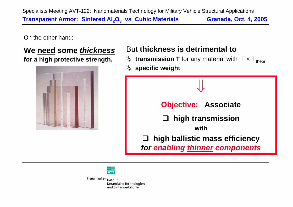
On the other hand:
We need some thicknessfor a high protective strength.
But thickness is detrimental to transmission T for any material with T < Ttheor
specific weight
⇓Objective: Associate
high transmissionwith
high ballistic mass efficiencyfor enabling thinner components
Specialists Meeting AVT-122: Nanomaterials Technology for Military Vehicle Structural ApplicationsTransparent Armor: Sintered Al2O3 vs Cubic Materials Granada, Oct. 4, 2005
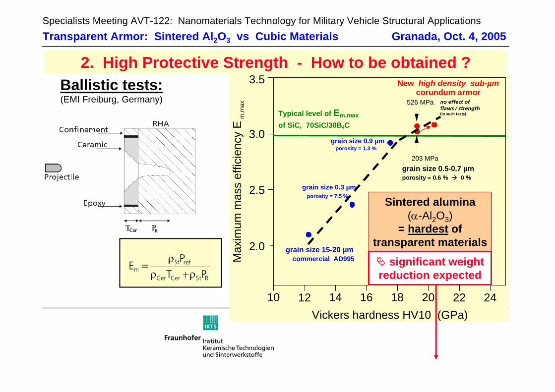
RStCerCer
refStm PT
PE
ρ+ρρ
=
10 12 14 16 18 20 22 24
Vickers hardness HV10 (GPa)
2.0
2.5
3.0
3.5 New high density sub-µm corundum armor
Max
imum
mas
s ef
ficie
ncy
E m
,max
commercial AD995
grain size 0.3 µmporosity = 7.5 %
grain size 0.9 µmporosity = 1.3 %
no effect of flaws / strength (in such tests)
203 MPagrain size 0.5-0.7 µmporosity ≈ 0.6 % 0 %
526 MPa
Typical level of Em,maxof SiC, 70SiC/30B4C
grain size 15-20 µm
Ballistic tests:(EMI Freiburg, Germany)
2. High Protective Strength - How to be obtained ?
Sintered alumina(α-Al2O3)
= hardest of transparent materials
significant weight reduction expected
Specialists Meeting AVT-122: Nanomaterials Technology for Military Vehicle Structural ApplicationsTransparent Armor: Sintered Al2O3 vs Cubic Materials Granada, Oct. 4, 2005
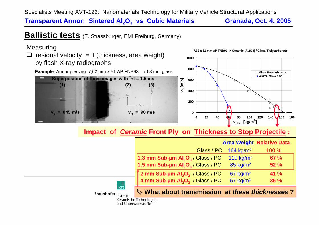
Ballistic tests (E. Strassburger, EMI Freiburg, Germany)
What about transmission at these thicknesses ?
Measuringresidual velocity = f (thickness, area weight)by flash X-ray radiographs
7,62 x 51 mm AP FNB91 -> Ceramic (Al2O3) / Glass/ Polycarbonate
0
200
400
600
800
1000
0 20 40 60 80 100 120 140 160 180 ρFTOT [kg/m2]
v R [m
/s]
Glass/PolycarbonateAl2O3 / Glass / PC
Example: Armor piercing 7,62 mm x 51 AP FNB93 → 63 mm glassSuperposition of three images with ∆t = 1.5 ms:
v0 = 845 m/s vR = 98 m/s
(1) (2) (3)
Area Weight Relative DataGlass / PC 164 kg/m2 100 %
1.3 mm Sub-µm Al2O3 / Glass / PC 110 kg/m2 67 %1.5 mm Sub-µm Al2O3 / Glass / PC 85 kg/m2 52 %
Impact of Ceramic Front Ply on Thickness to Stop Projectile :
2 mm Sub-µm Al2O3 / Glass / PC 67 kg/m2 41 %4 mm Sub-µm Al2O3 / Glass / PC 57 kg/m2 35 %
Specialists Meeting AVT-122: Nanomaterials Technology for Military Vehicle Structural ApplicationsTransparent Armor: Sintered Al2O3 vs Cubic Materials Granada, Oct. 4, 2005
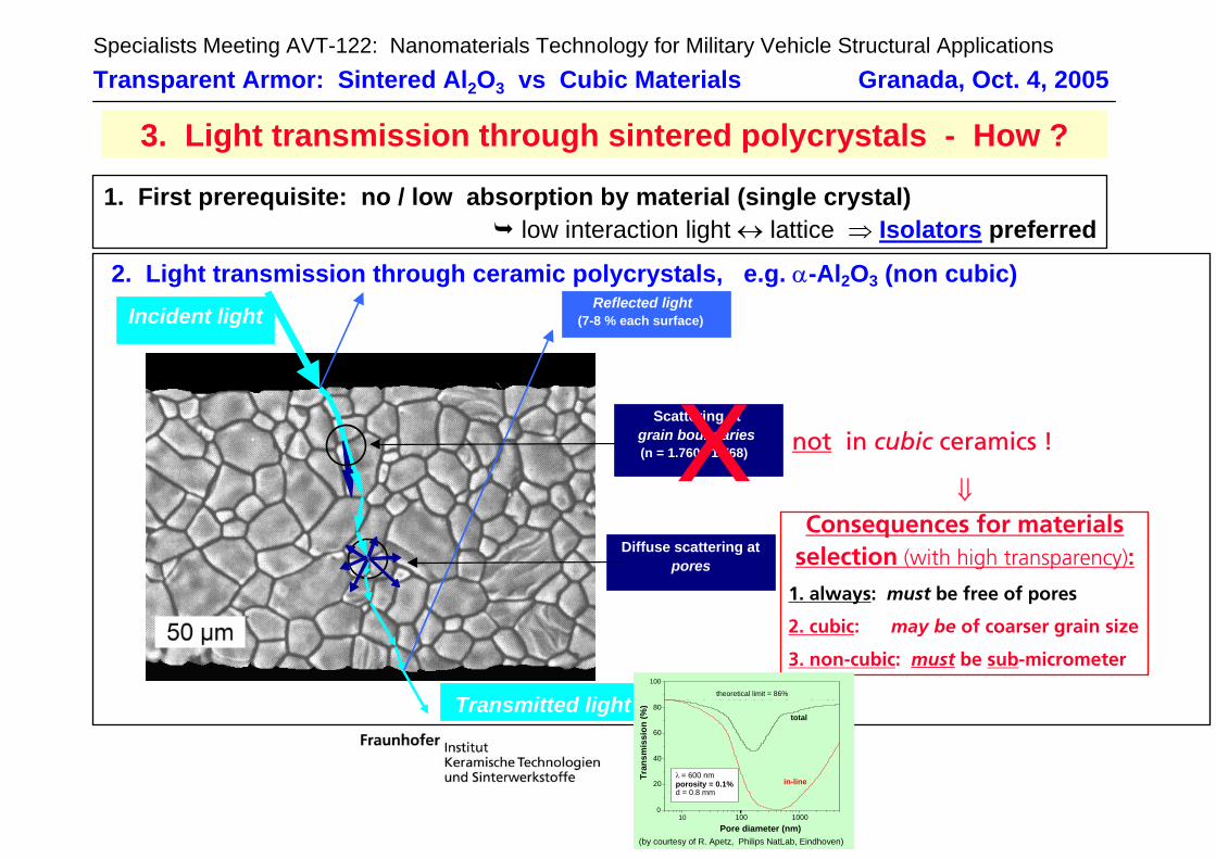
2. Light transmission through ceramic polycrystals, e.g. α-Al2O3 (non cubic)Incident light
Reflected light(7-8 % each surface)
Transmitted light
Scattering atgrain boundaries(n = 1.760 / 1.768)
Diffuse scattering atpores
1. First prerequisite: no / low absorption by material (single crystal)low interaction light ↔ lattice ⇒ Isolators preferred
3. Light transmission through sintered polycrystals - How ?
X not in cubic ceramics !
⇓Consequences for materials
selection (with high transparency):
2. cubic: may be of coarser grain size
3. non-cubic: must be sub-micrometer
1. always: must be free of pores
(by courtesy of R. Apetz, Philips NatLab, Eindhoven)
10 100 10000
20
40
60
80
100
theoretical limit = 86%
total
in-lineλ = 600 nmporosity = 0.1%d = 0.8 mm
Tran
smis
sion
(%)
Pore diameter (nm)
Specialists Meeting AVT-122: Nanomaterials Technology for Military Vehicle Structural ApplicationsTransparent Armor: Sintered Al2O3 vs Cubic Materials Granada, Oct. 4, 2005
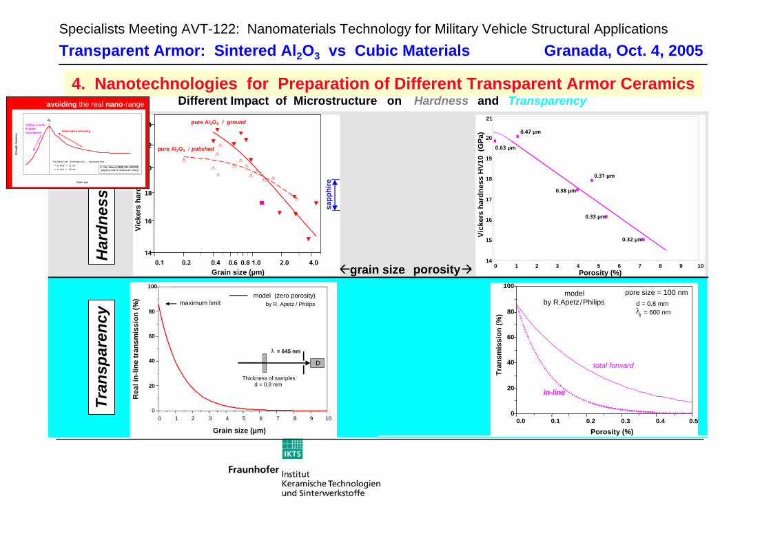
4. Nanotechnologies for Preparation of Different Transparent Armor CeramicsDifferent Impact of Microstructure on Hardness and Transparency
porosity 0 1 2 3 4 5 6 7 8 9 10Porosity (%)
14
15
16
17
18
19
20
21
Vick
ers
hard
ness
HV1
0 (G
Pa)
0.63 µm
0.47 µm
0.38 µm
0.31 µm
0.33 µm
0.32 µm
0.0 0.1 0.2 0.3 0.4 0.50
20
40
60
80
100
in-line
total forward
pore size = 100 nmd = 0.8 mmλo = 600 nm
Tran
smis
sion
(%)
Porosity (%)
modelby R. Apetz /Philips
0.1 0.2 0.4 0.6 0.8 1.0 2.0 4.0
14
16
18
20
22
24
Grain size (µm)
Vick
ers
hard
ness
HV1
0 (G
Pa)
pure Al2O3 / polished
pure Al2O3 / ground
sapp
hire
Har
dnes
s
maximum limit
D
0 1 2 3 4 5 6 7 8 9 100
20
40
60
80
100
Thickness of samplesd = 0.8 mm
λ = 645 nm
Rea
l in-
line
tran
smis
sion
(%)
Grain size (µm)
model (zero porosity)by R. Apetz / Philips
Tran
spar
ency
grain size
0
5
10
15
20
25
30
35
0 5 10 15 20 25 30 35 40 45 50
Grain size
Stre
ngth
, Har
dnes
s
S. Yip, Nature (1998) 391, 532-533[adapting Nieh & Wadsworth 1991]
"No theory yet. Estimate of dc ... assuming that ..." --> dc (Pd) = 11 nm --> dc (Cu) = 19 nm
sliding eventsin grainboundaries dislocation blocking
dc
avoiding the real nano-range!
Specialists Meeting AVT-122: Nanomaterials Technology for Military Vehicle Structural ApplicationsTransparent Armor: Sintered Al2O3 vs Cubic Materials Granada, Oct. 4, 2005
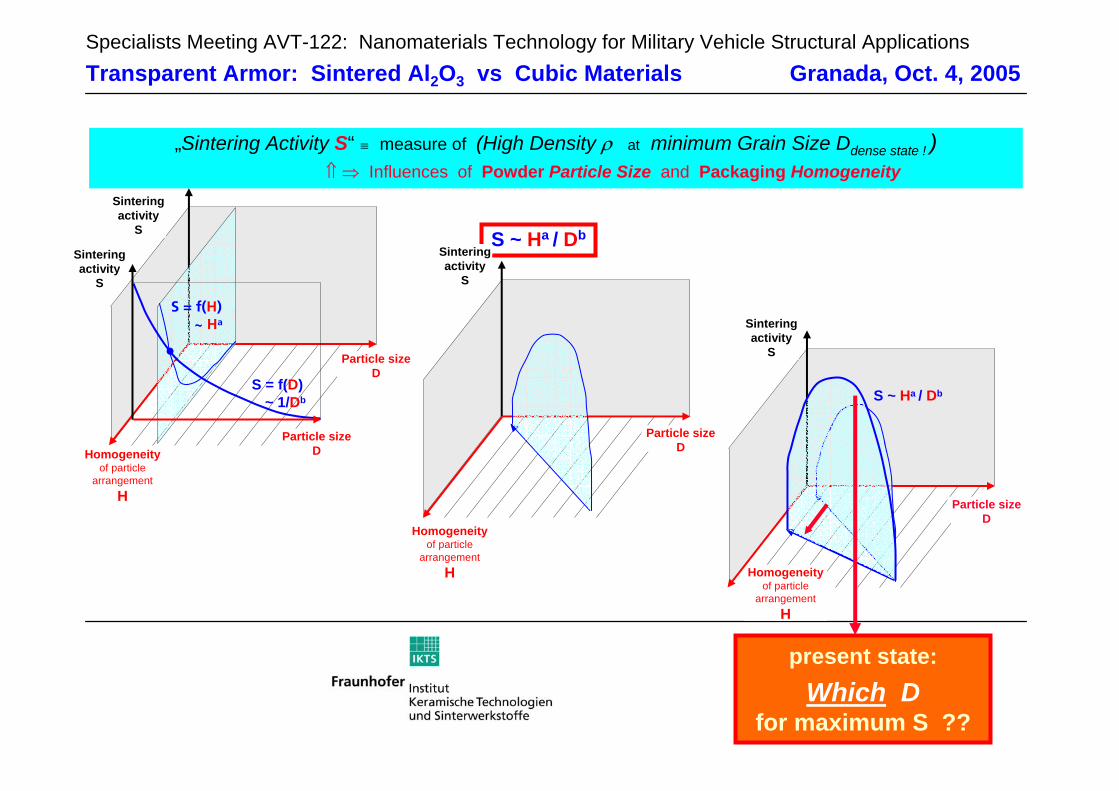
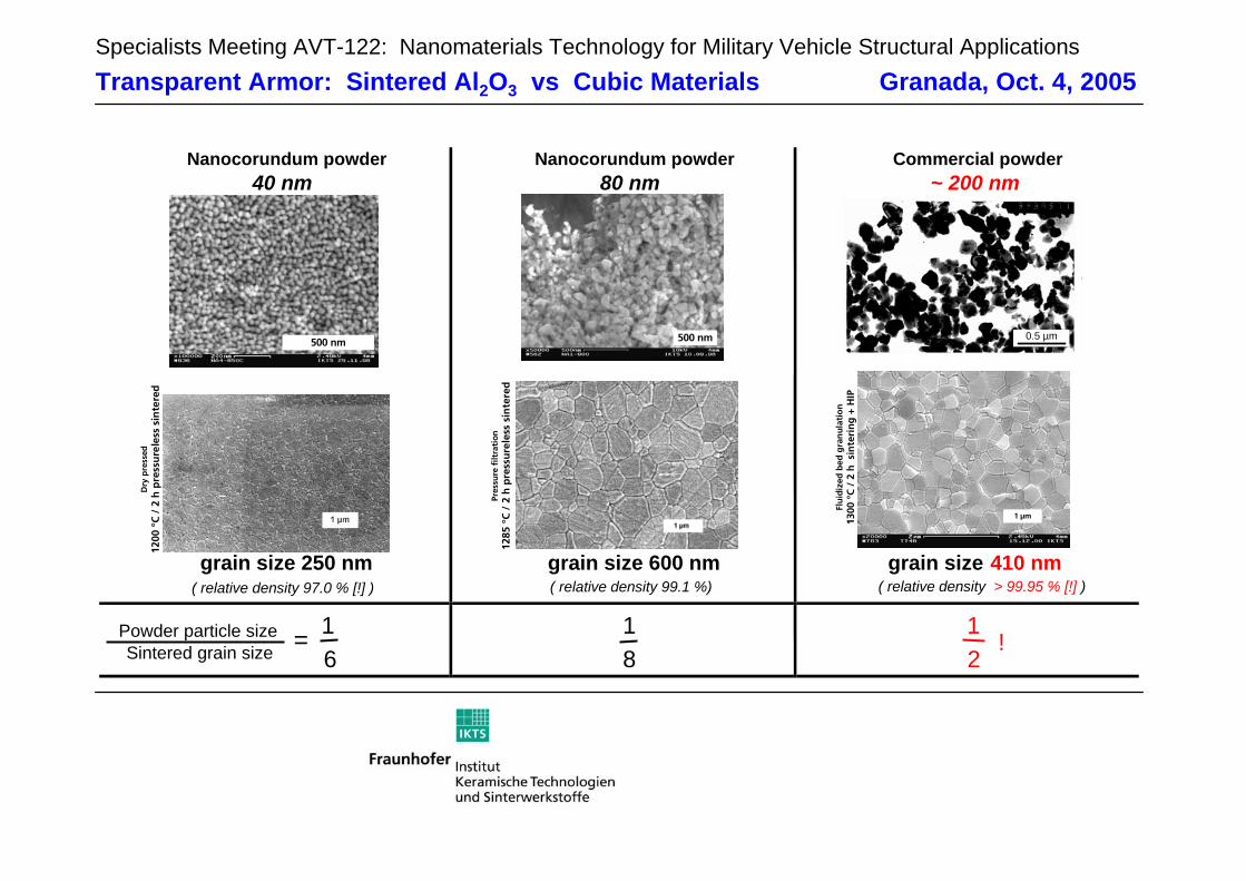
„Sintering Activity S“ ≡ measure of (High Density ρ at minimum Grain Size Ddense state ! )⇑ ⇒ Influences of Powder Particle Size and Packaging Homogeneity
S ~ Ha / Db
Particle size D
Sinteringactivity
S
Homogeneityof particle
arrangementH
S ~ Ha / Db
Particle size D
Homogeneityof particle
arrangementH
Sinteringactivity
S
Sinteringactivity
S
Homogeneityof particle
arrangementH
Particle size D
S = f(H)~ Ha
S = f(D)~ 1/Db
Particle size D
Sinteringactivity
S
present state:Which D
for maximum S ??
Specialists Meeting AVT-122: Nanomaterials Technology for Military Vehicle Structural ApplicationsTransparent Armor: Sintered Al2O3 vs Cubic Materials Granada, Oct. 4, 2005
Nanocorundum powder40 nm
Nanocorundum powder80 nm
Commercial powder~ 200 nm
grain size 250 nm( relative density 97.0 % [!] )
grain size 600 nm( relative density 99.1 %)
grain size 410 nm
Powder particle size 1Sintered grain size 6
18
12
=
500 nm
Dry
pre
ssed
1200
°C
/ 2
h p
ress
ure
less
sin
tere
d
500 nm
Pres
sure
filt
rati
on12
85 °
C /
2 h
pre
ssu
rele
ss s
inte
red
0.5 µm
Flu
idiz
ed b
ed g
ran
ula
tio
n13
00 °
C /
2 h
sin
teri
ng
+ H
IP
1 µm
( relative density > 99.95 % [!] )
!
Specialists Meeting AVT-122: Nanomaterials Technology for Military Vehicle Structural ApplicationsTransparent Armor: Sintered Al2O3 vs Cubic Materials Granada, Oct. 4, 2005
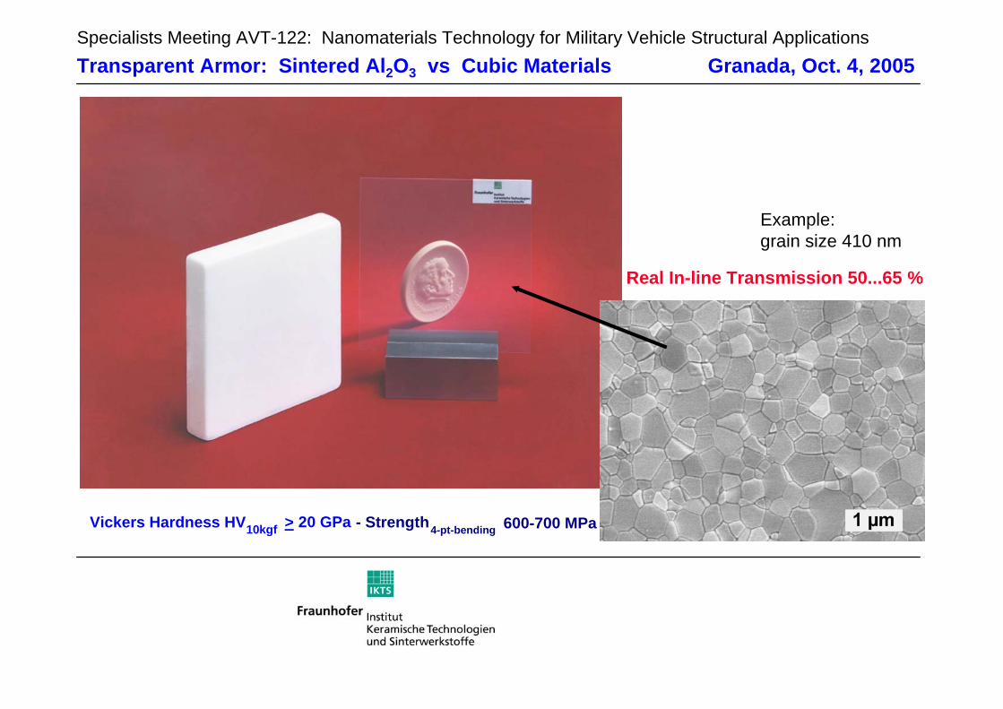
Vickers Hardness HV10kgf > 20 GPa - Strength4-pt-bending 600-700 MPa
Real In-line Transmission 50...65 %
Example:grain size 410 nm
Specialists Meeting AVT-122: Nanomaterials Technology for Military Vehicle Structural ApplicationsTransparent Armor: Sintered Al2O3 vs Cubic Materials Granada, Oct. 4, 2005
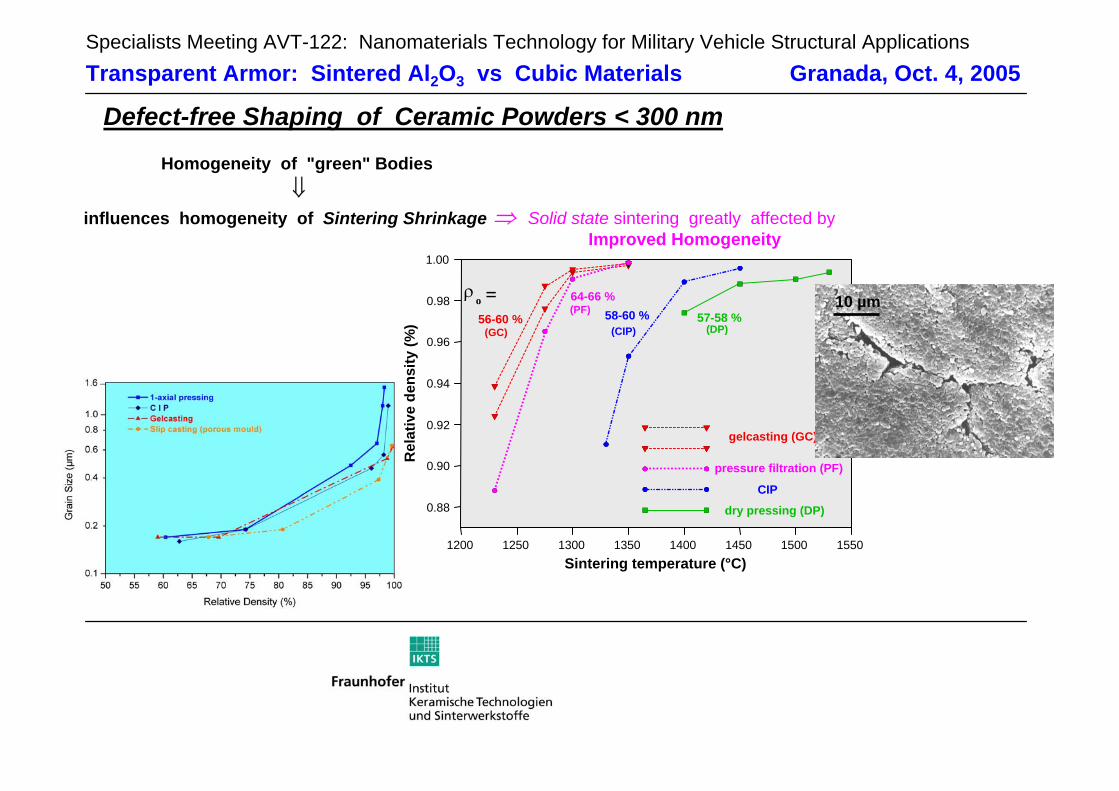
Defect-free Shaping of Ceramic Powders < 300 nmHomogeneity of "green" Bodies
⇓influences homogeneity of Sintering Shrinkage ⇒ Solid state sintering greatly affected by
Improved Homogeneity
Rel
ativ
e de
nsity
(%)
1200 1250 1300 1350 1400 1450 1500 1550
0.88
0.92
0.94
0.96
0.98 o =56-60 %
64-66 %58-60 % 57-58 %
(GC)
(PF)
(CIP) (DP)
dry pressing (DP)
CIP
pressure filtration (PF)
gelcasting (GC)
1.00
0.90
ρ
Sintering temperature (°C)
10 µm
Specialists Meeting AVT-122: Nanomaterials Technology for Military Vehicle Structural ApplicationsTransparent Armor: Sintered Al2O3 vs Cubic Materials Granada, Oct. 4, 2005
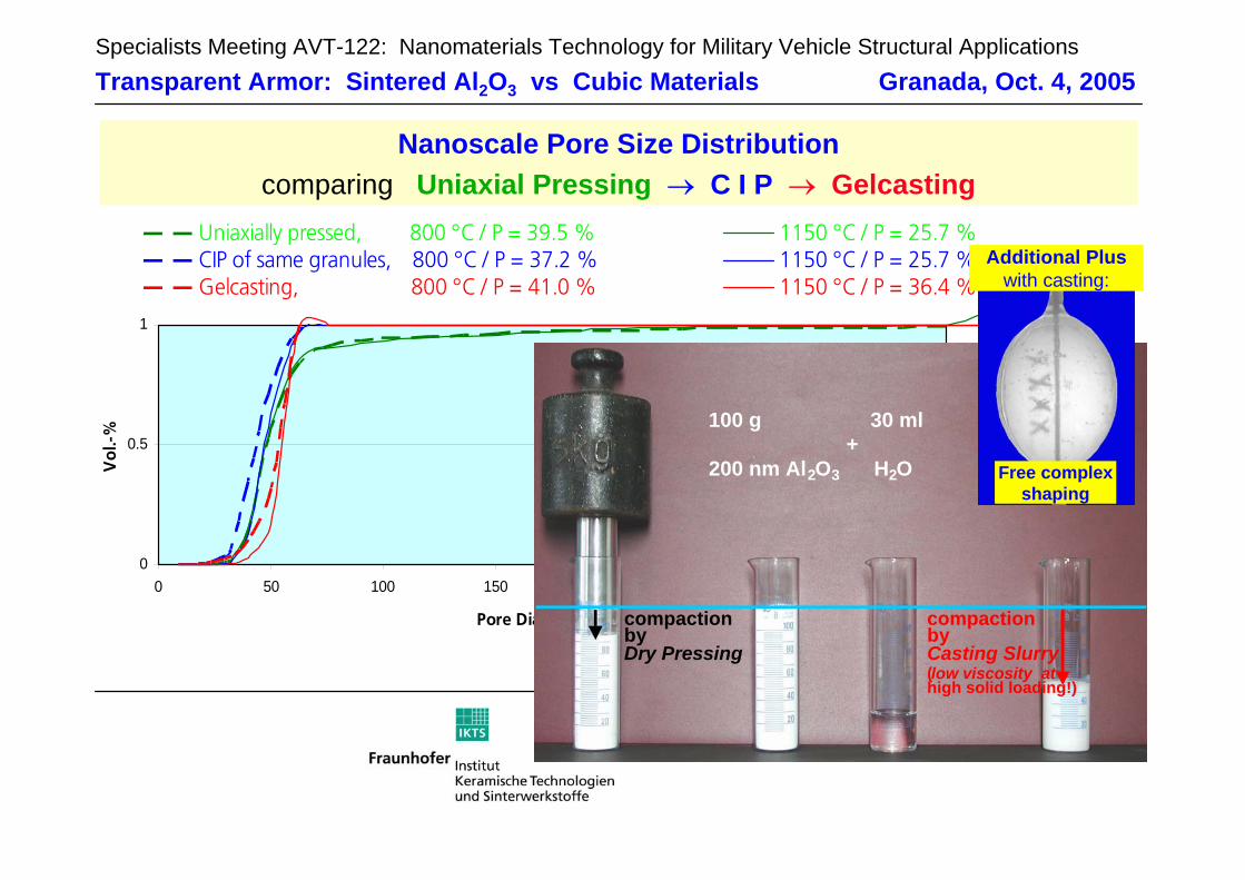
0
0.5
1
0 50 100 150 200 250 300 350
Pore Diameter (nm)
Vol
.-%
Uniaxially pressed, 800 °C / P = 39.5 % 1150 °C / P = 25.7 %CIP of same granules, 800 °C / P = 37.2 % 1150 °C / P = 25.7 %Gelcasting, 800 °C / P = 41.0 % 1150 °C / P = 36.4 %
Nanoscale Pore Size Distributioncomparing Uniaxial Pressing → C I P → Gelcasting
Rel
ativ
e de
nsity
(%)
1200 1250 1300 1350 1400 1450 1500 1550
0.88
0.92
0.94
0.96
0.98 o =56-60 %
64-66 %58-60 % 57-58 %
(GC)
(PF)
(CIP) (DP)
dry pressing (DP)
CIP
pressure filtration (PF)
gelcasting (GC)
1.00
0.90
ρ
Sintering temperature (°C)
100 g 30 ml+
200 nm Al2O3 H2O
compactionbyCasting Slurry(low viscosity athigh solid loading!)
compactionbyDry Pressing
Free complexshaping
Additional Plus with casting:
Specialists Meeting AVT-122: Nanomaterials Technology for Military Vehicle Structural ApplicationsTransparent Armor: Sintered Al2O3 vs Cubic Materials Granada, Oct. 4, 2005
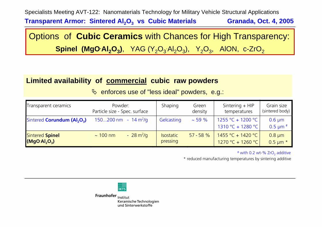
Limited availability of commercial cubic raw powdersenforces use of "less ideal" powders, e.g.:
Options of Cubic Ceramics with Chances for High Transparency:Spinel (MgO.Al2O3), YAG (Y2O3
.Al2O3), Y2O3, AlON, c-ZrO2
# with 0.2 wt-% ZrO2 additive* reduced manufacturing temperatures by sintering additive
Transparent ceramics Powder: Particle size - Spec. surface
Shaping Green density
Sintering + HIP temperatures
Grain size (sintered body)
Sintered Corundum (Al2O3) 150...200 nm - 14 m2/g Gelcasting ~ 59 % 1255 °C + 1200 °C 1310 °C + 1280 °C
0.6 µm 0.5 µm #
Sintered Spinel (MgO.Al2O3)
~ 100 nm - 28 m2/g Isostatic pressing
57 - 58 % 1455 °C + 1420 °C 1270 °C + 1260 °C
0.8 µm 0.5 µm *
Specialists Meeting AVT-122: Nanomaterials Technology for Military Vehicle Structural ApplicationsTransparent Armor: Sintered Al2O3 vs Cubic Materials Granada, Oct. 4, 2005
1 µm
# with 0.2 wt-% ZrO2 additive
* reduced manufacturing temperatures by sintering additive
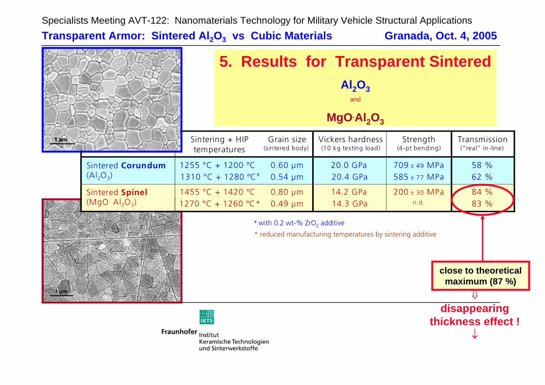
5. Results for Transparent SinteredAl2O3
and
MgO.Al2O3
⇓disappearing
thickness effect !↓
Transparent ceramics Sintering + HIP temperatures
Grain size (sintered body)
Vickers hardness (10 kg testing load)
Strength (4-pt bending)
Transmission ("real" in-line)
Sintered Corundum (Al2O3)
1255 °C + 1200 °C 1310 °C + 1280 °C#
0.60 µm 0.54 µm
20.0 GPa 20.4 GPa
709 ± 49 MPa 585 ± 77 MPa
58 % 62 %
Sintered Spinel (MgO. Al2O3)
1455 °C + 1420 °C 1270 °C + 1260 °C*
0.80 µm 0.49 µm
14.2 GPa 14.3 GPa
200 ± 30 MPa n.d.
84 % 83 %
close to theoreticalmaximum (87 %)
Specialists Meeting AVT-122: Nanomaterials Technology for Military Vehicle Structural ApplicationsTransparent Armor: Sintered Al2O3 vs Cubic Materials Granada, Oct. 4, 2005
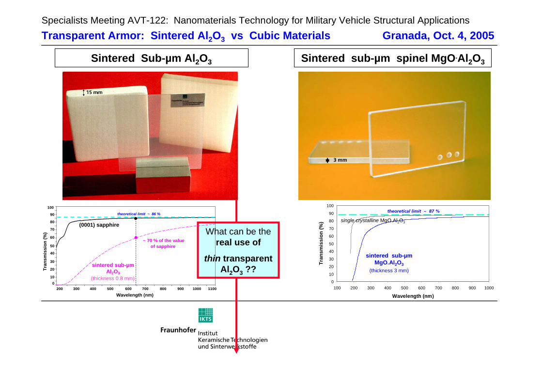
3 mm
Sintered Sub-µm Al2O3 Sintered sub-µm spinel MgO.Al2O3
What can be thereal use of
thin transparent Al2O3 ??
100
Wavelength (nm)
Tran
smis
sion
(%)
90
300200 1100600
sintered sub-µmAl2O3
(0001) sapphire
theoretical limit ~ 86 %
400 500 700 800 900 1000
~ 70 % of the valueof sapphire
80
70
60
50
40
30
20
100
(thickness 0.8 mm)
theoretical limit ~ 87 %
0
10
20
30
40
50
60
70
80
90
100
100 200 300 400 500 600 700 800 900 1000
Wavelength (nm)
Tran
smis
sion
(%)
sintered sub-µmMgO.Al2O3
(thickness 3 mm)
single crystalline MgO.Al2O3
Specialists Meeting AVT-122: Nanomaterials Technology for Military Vehicle Structural ApplicationsTransparent Armor: Sintered Al2O3 vs Cubic Materials Granada, Oct. 4, 2005
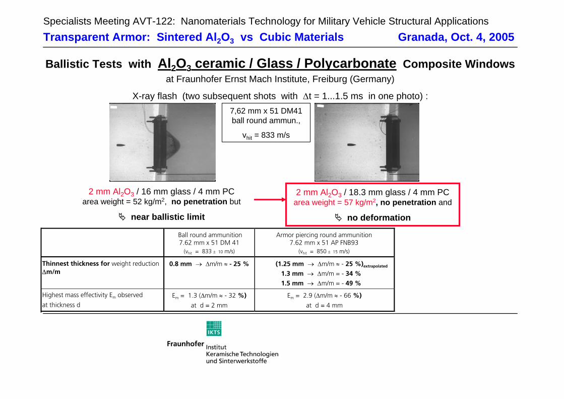
Ballistic Tests with Al2O3 ceramic / Glass / Polycarbonate Composite Windowsat Fraunhofer Ernst Mach Institute, Freiburg (Germany)
X-ray flash (two subsequent shots with ∆t = 1...1.5 ms in one photo) :
2 mm Al2O3 / 16 mm glass / 4 mm PCarea weight = 52 kg/m2, no penetration but
near ballistic limit
Ball round ammunition 7.62 mm x 51 DM 41
(vhit = 833 ± 10 m/s)
Armor piercing round ammunition 7.62 mm x 51 AP FNB93
(vhit = 850 ± 15 m/s)
Thinnest thickness for weight reduction ∆m/m
0.8 mm → ∆m/m ≈ - 25 % (1.25 mm → ∆m/m ≈ - 25 %)extrapolated
1.3 mm → ∆m/m = - 34 % 1.5 mm → ∆m/m = - 49 %
Highest mass effectivity Em observed
at thickness d Em = 1.3 (∆m/m ≈ - 32 %)
at d = 2 mm
Em = 2.9 (∆m/m ≈ - 66 %)
at d = 4 mm
2 mm Al2O3 / 18.3 mm glass / 4 mm PCarea weight = 57 kg/m2, no penetration and
no deformation
7,62 mm x 51 DM41 ball round ammun.,
vhit = 833 m/s
Specialists Meeting AVT-122: Nanomaterials Technology for Military Vehicle Structural ApplicationsTransparent Armor: Sintered Al2O3 vs Cubic Materials Granada, Oct. 4, 2005
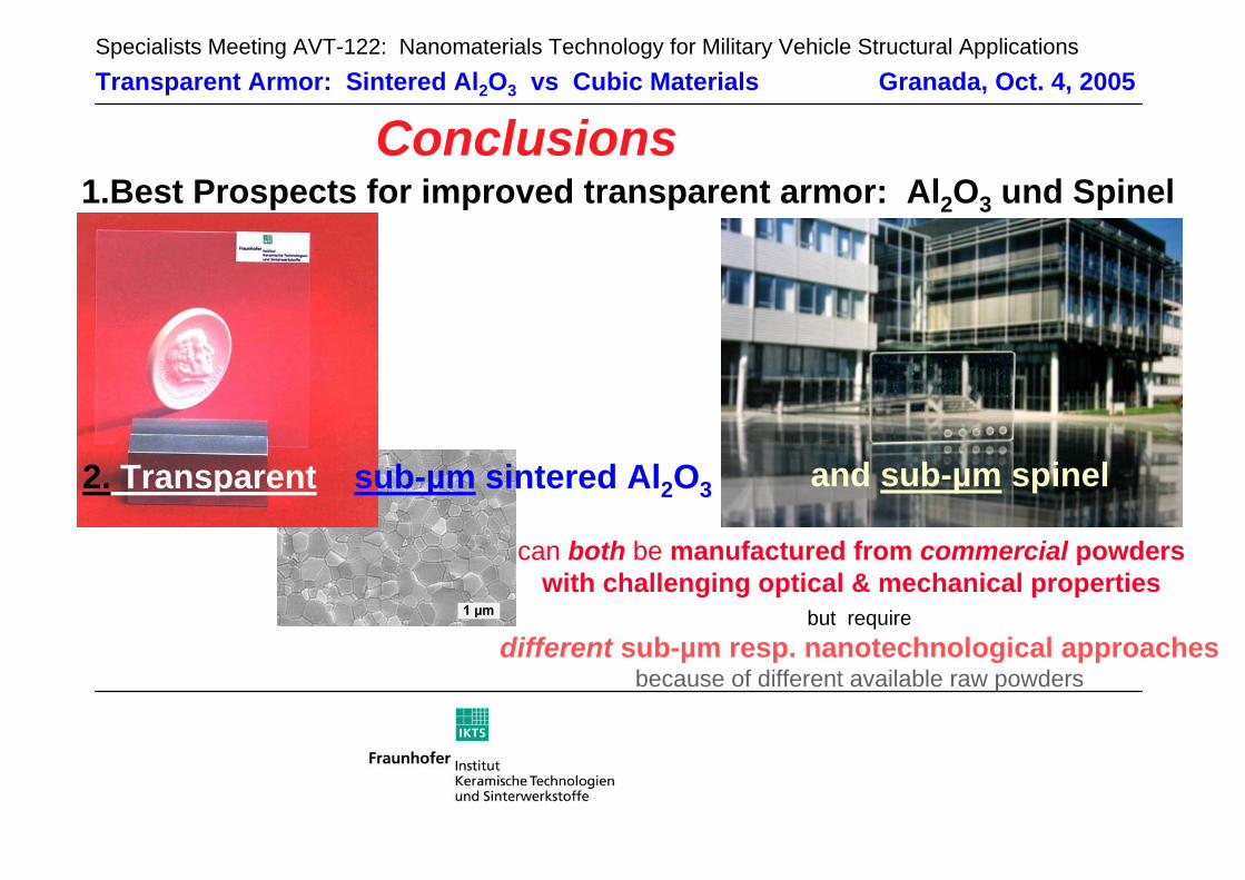
Conclusions
2. Transparent sub-µm sintered Al2O3
can both be manufactured from commercial powderswith challenging optical & mechanical properties
and sub-µm spinel
1.Best Prospects for improved transparent armor: Al2O3 und Spinel
but requiredifferent sub-µm resp. nanotechnological approaches
because of different available raw powders

![MVC Series - Middle Voltage Capacitors (100Vdc to … · Multilayer Ceramic Chip Capacitors. MVC. Series – Middle Voltage NP0 and X7R Capacitors [General Purpose – 100Vdc to 630Vdc]](https://static.fdocument.org/doc/165x107/5b96db8f09d3f2e10f8bead3/mvc-series-middle-voltage-capacitors-100vdc-to-multilayer-ceramic-chip-capacitors.jpg)