NPIM Shielded Power Inductors NPIM A Series
12
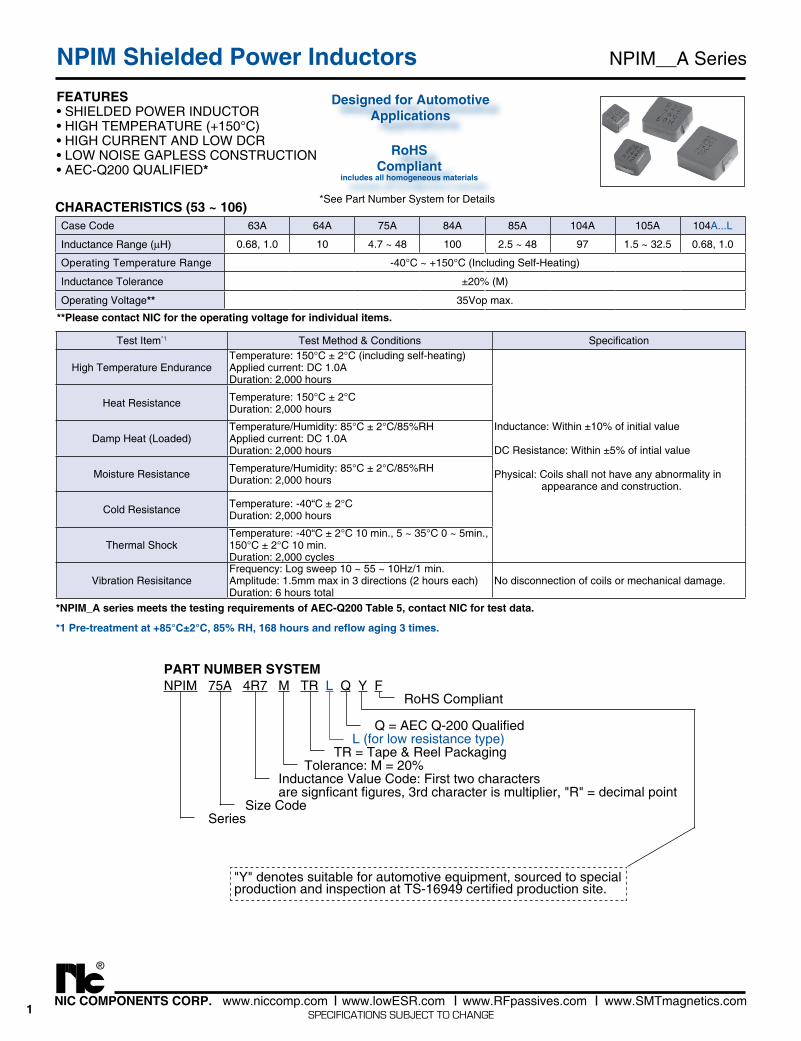
1 NIC COMPONENTS CORP. www.niccomp.com www.lowESR.com www.RFpassives.com www.SMTmagnetics.com ® SPECIFICATIONS SUBJECT TO CHANGE NPIM__A Series NPIM Shielded Power Inductors FEATURES • SHIELDED POWER INDUCTOR • HIGH TEMPERATURE (+150°C) • HIGH CURRENT AND LOW DCR • LOW NOISE GAPLESS CONSTRUCTION • AEC-Q200 QUALIFIED* CHARACTERISTICS (53 ~ 106) *See Part Number System for Details RoHS Compliant includes all homogeneous materials Case Code 63A 64A 75A 84A 85A 104A 105A 104A...L Inductance Range (μH) 0.68, 1.0 10 4.7 ~ 48 100 2.5 ~ 48 97 1.5 ~ 32.5 0.68, 1.0 Operating Temperature Range -40°C ~ +150°C (Including Self-Heating) Inductance Tolerance ±20% (M) Operating Voltage** 35Vop max. NPIM 75A 4R7 M TR L Q Y F RoHS Compliant Q = AEC Q-200 Qualified L (for low resistance type) TR = Tape & Reel Packaging Tolerance: M = 20% Inductance Value Code: First two characters are signficant figures, 3rd character is multiplier, "R" = decimal point Size Code Series PART NUMBER SYSTEM "Y" denotes suitable for automotive equipment, sourced to special production and inspection at TS-16949 certified production site. Test Item *1 Test Method & Conditions Specification High Temperature Endurance Temperature: 150°C ± 2°C (including self-heating) Applied current: DC 1.0A Duration: 2,000 hours Inductance: Within ±10% of initial value DC Resistance: Within ±5% of intial value Physical: Coils shall not have any abnormality in appearance and construction. Heat Resistance Temperature: 150°C ± 2°C Duration: 2,000 hours Damp Heat (Loaded) Temperature/Humidity: 85°C ± 2°C/85%RH Applied current: DC 1.0A Duration: 2,000 hours Moisture Resistance Temperature/Humidity: 85°C ± 2°C/85%RH Duration: 2,000 hours Cold Resistance Temperature: -40“C ± 2°C Duration: 2,000 hours Thermal Shock Temperature: -40“C ± 2°C 10 min., 5 ~ 35°C 0 ~ 5min., 150°C ± 2°C 10 min. Duration: 2,000 cycles Vibration Resisitance Frequency: Log sweep 10 ~ 55 ~ 10Hz/1 min. Amplitude: 1.5mm max in 3 directions (2 hours each) Duration: 6 hours total No disconnection of coils or mechanical damage. *NPIM_A series meets the testing requirements of AEC-Q200 Table 5, contact NIC for test data. *1 Pre-treatment at +85°C±2°C, 85% RH, 168 hours and reflow aging 3 times. Designed for Automotive Applications **Please contact NIC for the operating voltage for individual items.
Transcript of NPIM Shielded Power Inductors NPIM A Series
1NIC COMPONENTS CORP. www.niccomp.com www.lowESR.com www.RFpassives.com www.SMTmagnetics.com
®
SPECIFICATIONS SUBJECT TO CHANGE
NPIM__A SeriesNPIM Shielded Power InductorsFEATURES• SHIELDED POWER INDUCTOR• HIGH TEMPERATURE (+150°C)• HIGH CURRENT AND LOW DCR• LOW NOISE GAPLESS CONSTRUCTION• AEC-Q200 QUALIFIED*
CHARACTERISTICS (53 ~ 106)*See Part Number System for Details
RoHSCompliant
includes all homogeneous materials
Case Code 63A 64A 75A 84A 85A 104A 105A 104A...L
Inductance Range (μH) 0.68, 1.0 10 4.7 ~ 48 100 2.5 ~ 48 97 1.5 ~ 32.5 0.68, 1.0
Operating Temperature Range -40°C ~ +150°C (Including Self-Heating)
Inductance Tolerance ±20% (M)
Operating Voltage** 35Vop max.
NPIM 75A 4R7 M TR L Q Y F RoHS Compliant Q = AEC Q-200 Qualified L (for low resistance type) TR = Tape & Reel Packaging Tolerance: M = 20% Inductance Value Code: First two characters are signficant figures, 3rd character is multiplier, "R" = decimal point Size Code Series
PART NUMBER SYSTEM
"Y" denotes suitable for automotive equipment, sourced to specialproduction and inspection at TS-16949 certified production site.
Test Item*1 Test Method & Conditions Specification
High Temperature EnduranceTemperature: 150°C ± 2°C (including self-heating)Applied current: DC 1.0ADuration: 2,000 hours
Inductance: Within ±10% of initial value
DC Resistance: Within ±5% of intial value
Physical: Coils shall not have any abnormality in appearance and construction.
Heat Resistance Temperature: 150°C ± 2°CDuration: 2,000 hours
Damp Heat (Loaded)Temperature/Humidity: 85°C ± 2°C/85%RHApplied current: DC 1.0ADuration: 2,000 hours
Moisture Resistance Temperature/Humidity: 85°C ± 2°C/85%RHDuration: 2,000 hours
Cold Resistance Temperature: -40“C ± 2°CDuration: 2,000 hours
Thermal ShockTemperature: -40“C ± 2°C 10 min., 5 ~ 35°C 0 ~ 5min., 150°C ± 2°C 10 min.Duration: 2,000 cycles
Vibration ResisitanceFrequency: Log sweep 10 ~ 55 ~ 10Hz/1 min.Amplitude: 1.5mm max in 3 directions (2 hours each)Duration: 6 hours total
No disconnection of coils or mechanical damage.
*NPIM_A series meets the testing requirements of AEC-Q200 Table 5, contact NIC for test data.
*1 Pre-treatment at +85°C±2°C, 85% RH, 168 hours and reflow aging 3 times.
Designed for Automotive Applications
**Please contact NIC for the operating voltage for individual items.
2NIC COMPONENTS CORP. www.niccomp.com www.lowESR.com www.RFpassives.com www.SMTmagnetics.com
®
SPECIFICATIONS SUBJECT TO CHANGE
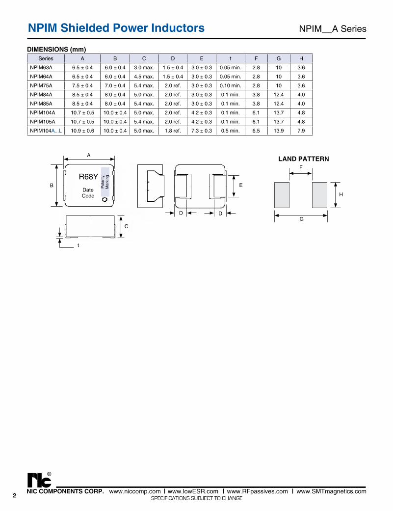
Series A B C D E t F G H
NPIM63A 6.5 ± 0.4 6.0 ± 0.4 3.0 max. 1.5 ± 0.4 3.0 ± 0.3 0.05 min. 2.8 10 3.6
NPIM64A 6.5 ± 0.4 6.0 ± 0.4 4.5 max. 1.5 ± 0.4 3.0 ± 0.3 0.05 min. 2.8 10 3.6
NPIM75A 7.5 ± 0.4 7.0 ± 0.4 5.4 max. 2.0 ref. 3.0 ± 0.3 0.10 min. 2.8 10 3.6
NPIM84A 8.5 ± 0.4 8.0 ± 0.4 5.0 max. 2.0 ref. 3.0 ± 0.3 0.1 min. 3.8 12.4 4.0
NPIM85A 8.5 ± 0.4 8.0 ± 0.4 5.4 max. 2.0 ref. 3.0 ± 0.3 0.1 min. 3.8 12.4 4.0
NPIM104A 10.7 ± 0.5 10.0 ± 0.4 5.0 max. 2.0 ref. 4.2 ± 0.3 0.1 min. 6.1 13.7 4.8
NPIM105A 10.7 ± 0.5 10.0 ± 0.4 5.4 max. 2.0 ref. 4.2 ± 0.3 0.1 min. 6.1 13.7 4.8
NPIM104A...L 10.9 ± 0.6 10.0 ± 0.4 5.0 max. 1.8 ref. 7.3 ± 0.3 0.5 min. 6.5 13.9 7.9
DIMENSIONS (mm)
NPIM__A SeriesNPIM Shielded Power Inductors
H
LAND PATTERN
G
F
C
t
A
E
D
BR68Y
DateCode
Pol
arity
Mar
king
D
3NIC COMPONENTS CORP. www.niccomp.com www.lowESR.com www.RFpassives.com www.SMTmagnetics.com
®
SPECIFICATIONS SUBJECT TO CHANGE
NPIM__A SeriesNPIM Shielded Power Inductors
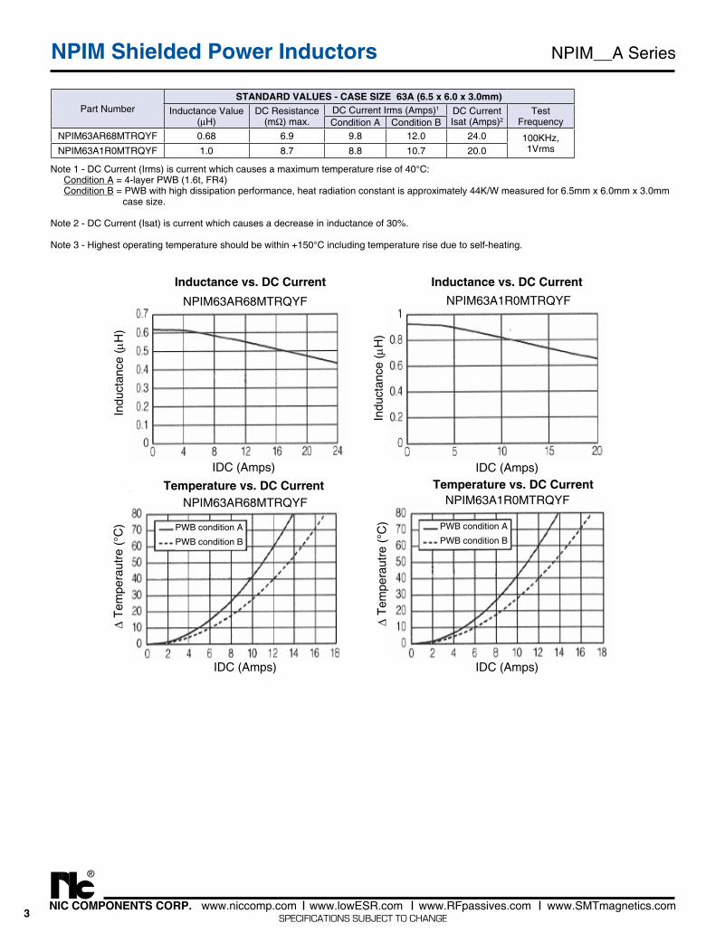
Part NumberSTANDARD VALUES - CASE SIZE 63A (6.5 x 6.0 x 3.0mm)
Inductance Value(μH)
DC Resistance(mΩ) max.
DC Current Irms (Amps)1 DC CurrentIsat (Amps)2
Test FrequencyCondition A Condition B
NPIM63AR68MTRQYF 0.68 6.9 9.8 12.0 24.0 100KHz, 1VrmsNPIM63A1R0MTRQYF 1.0 8.7 8.8 10.7 20.0
NPIM63AR68MTRQYF
Indu
ctan
ce (m
H)
IDC (Amps)
NPIM63A1R0MTRQYF
Indu
ctan
ce (m
H)
IDC (Amps)
NPIM63AR68MTRQYF
IDC (Amps)
D Te
mpe
raut
re (°
C)
NPIM63A1R0MTRQYF
IDC (Amps)
D Te
mpe
raut
re (°
C) PWB condition A
PWB condition BPWB condition A
PWB condition B
Note 1 - DC Current (Irms) is current which causes a maximum temperature rise of 40°C: Condition A = 4-layer PWB (1.6t, FR4) Condition B = PWB with high dissipation performance, heat radiation constant is approximately 44K/W measured for 6.5mm x 6.0mm x 3.0mm case size.
Note 2 - DC Current (Isat) is current which causes a decrease in inductance of 30%.
Note 3 - Highest operating temperature should be within +150°C including temperature rise due to self-heating.
Inductance vs. DC Current
Temperature vs. DC Current
Inductance vs. DC Current
Temperature vs. DC Current
4NIC COMPONENTS CORP. www.niccomp.com www.lowESR.com www.RFpassives.com www.SMTmagnetics.com
®
SPECIFICATIONS SUBJECT TO CHANGE
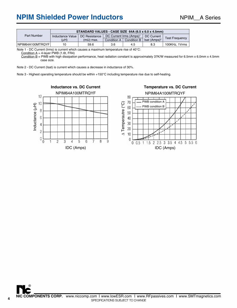
Part NumberSTANDARD VALUES - CASE SIZE 64A (6.5 x 6.0 x 4.5mm)
Inductance Value(μH)
DC Resistance(mΩ) max.
DC Current Irms (Amps)1 DC CurrentIsat (Amps)2 Test Frequency
Condition A Condition BNPIM64A100MTRQYF 10 59.6 3.6 4.5 8.3 100KHz, 1Vrms
NPIM64A100MTRQYF
Indu
ctan
ce (m
H)
IDC (Amps)
NPIM64A100MTRQYF
IDC (Amps)
D Te
mpe
raut
re (°
C) PWB condition A
PWB condition B
Note 1 - DC Current (Irms) is current which causes a maximum temperature rise of 40°C: Condition A = 4-layer PWB (1.6t, FR4) Condition B = PWB with high dissipation performance, heat radiation constant is approximately 37K/W measured for 6.5mm x 6.0mm x 4.5mm case size.
Note 2 - DC Current (Isat) is current which causes a decrease in inductance of 30%.
Note 3 - Highest operating temperature should be within +150°C including temperature rise due to self-heating.
NPIM__A SeriesNPIM Shielded Power Inductors
Inductance vs. DC Current Temperature vs. DC Current
5NIC COMPONENTS CORP. www.niccomp.com www.lowESR.com www.RFpassives.com www.SMTmagnetics.com
®
SPECIFICATIONS SUBJECT TO CHANGE
NPIM__A SeriesNPIM Shielded Power Inductors
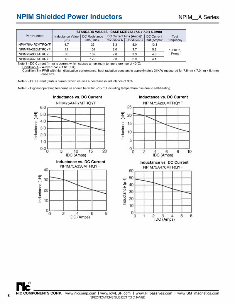
Part NumberSTANDARD VALUES - CASE SIZE 75A (7.5 x 7.0 x 5.4mm)
Inductance Value(μH)
DC Resistance(mΩ) max.
DC Current Irms (Amps)1 DC CurrentIsat (Amps)2
Test FrequencyCondition A Condition B
NPIM75A4R7MTRQYF 4.7 23 6.3 8.0 13.1
100KHz, 1Vrms
NPIM75A220MTRQYF 22 102 3.0 3.7 5.8
NPIM75A330MTRQYF 33 132 2.6 3.3 4.8
NPIM75A470MTRQYF 48 172 2.3 2.9 4.1
NPIM75A4R7MTRQYF
Indu
ctan
ce (m
H)
IDC (Amps)
NPIM75A220MTRQYF
Indu
ctan
ce (m
H)
IDC (Amps)
NPIM75A330MTRQYF
Indu
ctan
ce (m
H)
IDC (Amps)
NPIM75A470MTRQYF
Indu
ctan
ce (m
H)
IDC (Amps)
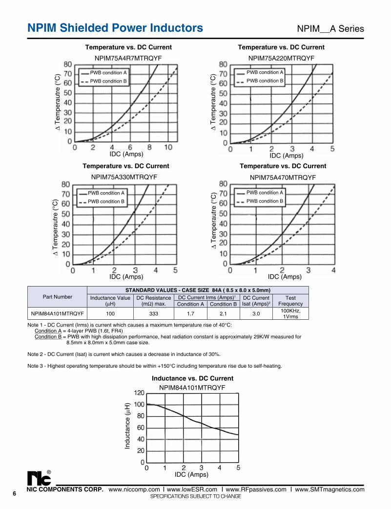
Note 1 - DC Current (Irms) is current which causes a maximum temperature rise of 40°C: Condition A = 4-layer PWB (1.6t, FR4) Condition B = PWB with high dissipation performance, heat radiation constant is approximately 31K/W measured for 7.5mm x 7.0mm x 5.4mm case size.
Note 2 - DC Current (Isat) is current which causes a decrease in inductance of 30%.
Note 3 - Highest operating temperature should be within +150°C including temperature rise due to self-heating.
Inductance vs. DC Current Inductance vs. DC Current
Inductance vs. DC Current Inductance vs. DC Current
6NIC COMPONENTS CORP. www.niccomp.com www.lowESR.com www.RFpassives.com www.SMTmagnetics.com
®
SPECIFICATIONS SUBJECT TO CHANGE
NPIM__A SeriesNPIM Shielded Power Inductors
PWB condition A
PWB condition B
PWB condition A
PWB condition B
IDC (Amps) IDC (Amps)
D Te
mpe
raut
re (°
C)
D Te
mpe
raut
re (°
C)
NPIM75A330MTRQYF NPIM75A470MTRQYF
PWB condition A
PWB condition B
PWB condition A
PWB condition B
NPIM75A4R7MTRQYF NPIM75A220MTRQYF
IDC (Amps) IDC (Amps)
D Te
mpe
raut
re (°
C)
D Te
mpe
raut
re (°
C)
Temperature vs. DC Current Temperature vs. DC Current
Temperature vs. DC Current Temperature vs. DC Current
Part NumberSTANDARD VALUES - CASE SIZE 84A ( 8.5 x 8.0 x 5.0mm)
Inductance Value(μH)
DC Resistance(mΩ) max.
DC Current Irms (Amps)1 DC CurrentIsat (Amps)2
Test FrequencyCondition A Condition B
NPIM84A101MTRQYF 100 333 1.7 2.1 3.0 100KHz, 1Vrms
Note 1 - DC Current (Irms) is current which causes a maximum temperature rise of 40°C: Condition A = 4-layer PWB (1.6t, FR4) Condition B = PWB with high dissipation performance, heat radiation constant is approximately 29K/W measured for 8.5mm x 8.0mm x 5.0mm case size.
Note 2 - DC Current (Isat) is current which causes a decrease in inductance of 30%.
Note 3 - Highest operating temperature should be within +150°C including temperature rise due to self-heating.
NPIM84A101MTRQYF
Indu
ctan
ce (m
H)
IDC (Amps)
Inductance vs. DC Current
7NIC COMPONENTS CORP. www.niccomp.com www.lowESR.com www.RFpassives.com www.SMTmagnetics.com
®
SPECIFICATIONS SUBJECT TO CHANGE
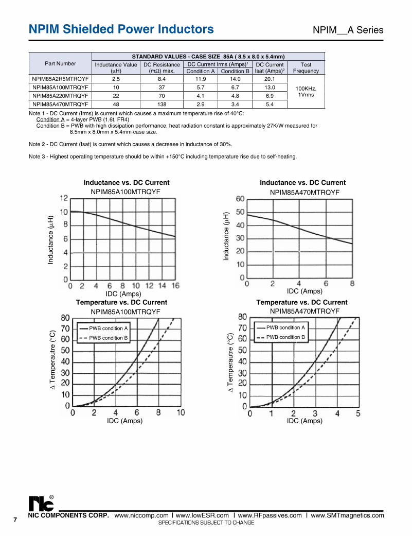
Part NumberSTANDARD VALUES - CASE SIZE 85A ( 8.5 x 8.0 x 5.4mm)
Inductance Value(μH)
DC Resistance(mΩ) max.
DC Current Irms (Amps)1 DC CurrentIsat (Amps)2
Test FrequencyCondition A Condition B
NPIM85A2R5MTRQYF 2.5 8.4 11.9 14.0 20.1
100KHz, 1Vrms
NPIM85A100MTRQYF 10 37 5.7 6.7 13.0
NPIM85A220MTRQYF 22 70 4.1 4.8 6.9
NPIM85A470MTRQYF 48 138 2.9 3.4 5.4
PWB condition A
PWB condition B
PWB condition A
PWB condition B
IDC (Amps)
NPIM85A470MTRQYF
IDC (Amps)
NPIM85A470MTRQYF
IDC (Amps)
NPIM85A100MTRQYF
IDC (Amps)
NPIM85A100MTRQYF
Indu
ctan
ce (m
H)
D Te
mpe
raut
re (°
C)
Indu
ctan
ce (m
H)
D Te
mpe
raut
re (°
C)
Note 1 - DC Current (Irms) is current which causes a maximum temperature rise of 40°C: Condition A = 4-layer PWB (1.6t, FR4) Condition B = PWB with high dissipation performance, heat radiation constant is approximately 27K/W measured for 8.5mm x 8.0mm x 5.4mm case size.
Note 2 - DC Current (Isat) is current which causes a decrease in inductance of 30%.
Note 3 - Highest operating temperature should be within +150°C including temperature rise due to self-heating.
NPIM__A SeriesNPIM Shielded Power Inductors
Inductance vs. DC Current
Temperature vs. DC Current
Inductance vs. DC Current
Temperature vs. DC Current
8NIC COMPONENTS CORP. www.niccomp.com www.lowESR.com www.RFpassives.com www.SMTmagnetics.com
®
SPECIFICATIONS SUBJECT TO CHANGE
NPIM__A SeriesNPIM Shielded Power Inductors
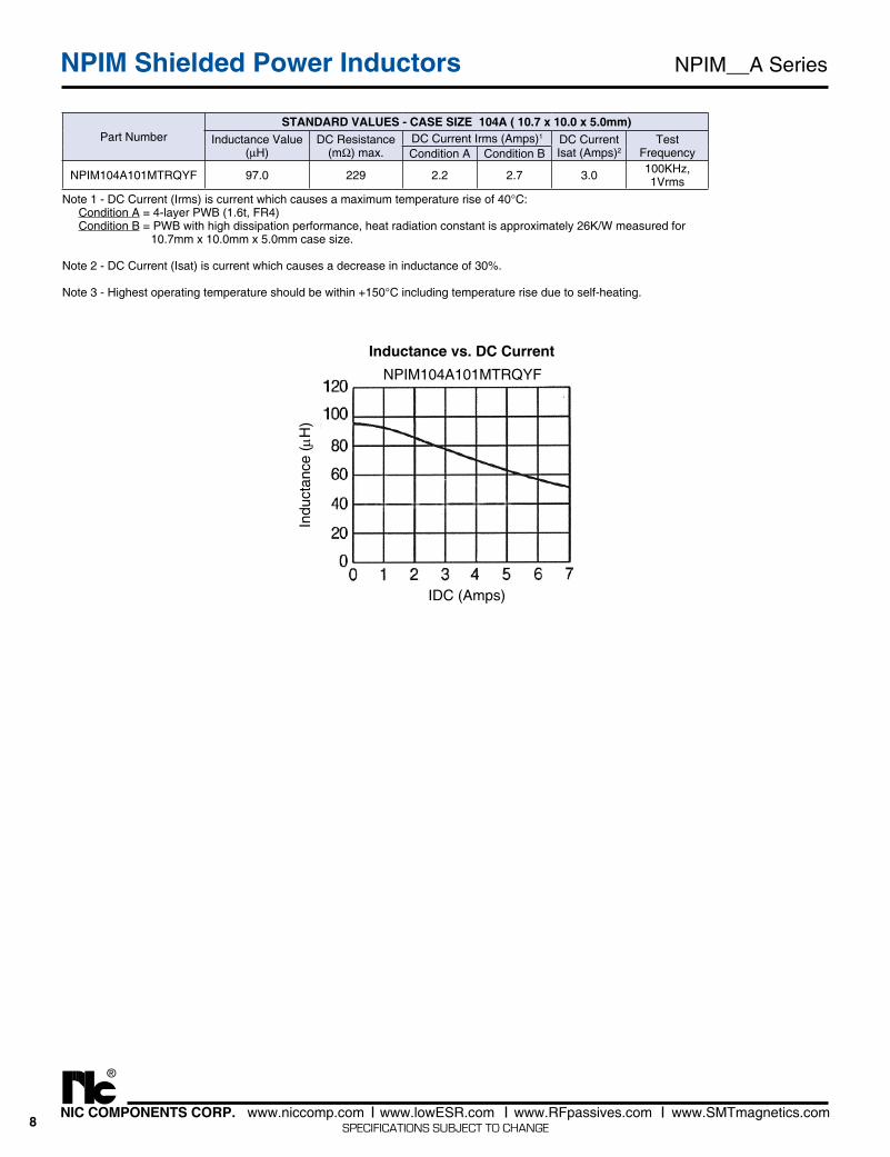
Part NumberSTANDARD VALUES - CASE SIZE 104A ( 10.7 x 10.0 x 5.0mm)
Inductance Value(μH)
DC Resistance(mΩ) max.
DC Current Irms (Amps)1 DC CurrentIsat (Amps)2
Test FrequencyCondition A Condition B
NPIM104A101MTRQYF 97.0 229 2.2 2.7 3.0 100KHz, 1Vrms
Note 1 - DC Current (Irms) is current which causes a maximum temperature rise of 40°C: Condition A = 4-layer PWB (1.6t, FR4) Condition B = PWB with high dissipation performance, heat radiation constant is approximately 26K/W measured for 10.7mm x 10.0mm x 5.0mm case size.
Note 2 - DC Current (Isat) is current which causes a decrease in inductance of 30%.
Note 3 - Highest operating temperature should be within +150°C including temperature rise due to self-heating.
IDC (Amps)
NPIM104A101MTRQYF
Indu
ctan
ce (m
H)
Inductance vs. DC Current
9NIC COMPONENTS CORP. www.niccomp.com www.lowESR.com www.RFpassives.com www.SMTmagnetics.com
®
SPECIFICATIONS SUBJECT TO CHANGE
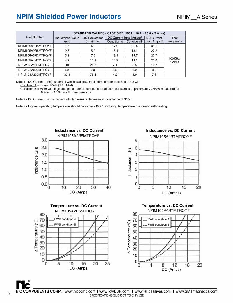
Part NumberSTANDARD VALUES - CASE SIZE 105A ( 10.7 x 10.0 x 5.4mm)
Inductance Value(μH)
DC Resistance(mΩ) max.
DC Current Irms (Amps)1 DC CurrentIsat (Amps)2
Test FrequencyCondition A Condition B
NPIM105A1R5MTRQYF 1.5 4.2 17.9 21.4 35.1
100KHz, 1Vrms
NPIM105A2R5MTRQYF 2.5 5.9 15.1 18.1 27.2
NPIM105A3R3MTRQYF 3.3 7.9 13.1 15.7 22.7
NPIM105A4R7MTRQYF 4.7 11.3 10.9 13.1 20.0
NPIM105A100MTRQYF 10 26.2 7.1 8.5 10.7
NPIM105A220MTRQYF 22 50 5.2 6.2 8.8
NPIM105A330MTRQYF 32.5 75.4 4.2 5.0 7.6
IDC (Amps)
NPIM105A2R5MTRQYF
IDC (Amps)
NPIM105A2R5MTRQYF
Indu
ctan
ce (m
H)
D Te
mpe
raut
re (°
C) PWB condition A
PWB condition B
IDC (Amps)
NPIM105A4R7MTRQYF
IDC (Amps)
NPIM105A4R7MTRQYF
Indu
ctan
ce (m
H)
D Te
mpe
raut
re (°
C) PWB condition A
PWB condition B
NPIM__A SeriesNPIM Shielded Power Inductors
Note 1 - DC Current (Irms) is current which causes a maximum temperature rise of 40°C: Condition A = 4-layer PWB (1.6t, FR4) Condition B = PWB with high dissipation performance, heat radiation constant is approximately 23K/W measured for 10.7mm x 10.0mm x 5.4mm case size.
Note 2 - DC Current (Isat) is current which causes a decrease in inductance of 30%.
Note 3 - Highest operating temperature should be within +150°C including temperature rise due to self-heating.
Inductance vs. DC Current
Temperature vs. DC Current
Inductance vs. DC Current
Temperature vs. DC Current
10NIC COMPONENTS CORP. www.niccomp.com www.lowESR.com www.RFpassives.com www.SMTmagnetics.com
®
SPECIFICATIONS SUBJECT TO CHANGE
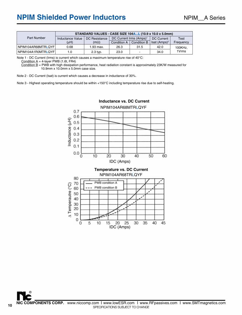
Part NumberSTANDARD VALUES - CASE SIZE 104A...L (10.9 x 10.0 x 5.0mm)
Inductance Value(μH)
DC Resistance(mΩ)
DC Current Irms (Amps)1 DC CurrentIsat (Amps)2
Test FrequencyCondition A Condition B
NPIM104AR68MTRLQYF 0.68 1.93 max. 26.3 31.5 42.0 100KHz, 1VrmsNPIM104A1R0MTRLQYF 1.0 2.3 typ. 23.0 - 34.0
IDC (Amps)
NPIM104AR68MTRLQYF
IDC (Amps)
NPIM104AR68TRLQYF
Indu
ctan
ce (m
H)
D Te
mpe
raut
re (°
C) PWB condition A
PWB condition B
NPIM__A SeriesNPIM Shielded Power Inductors
Note 1 - DC Current (Irms) is current which causes a maximum temperature rise of 40°C: Condition A = 4-layer PWB (1.6t, FR4) Condition B = PWB with high dissipation performance, heat radiation constant is approximately 23K/W measured for 10.9mm x 10.0mm x 5.0mm case size.
Note 2 - DC Current (Isat) is current which causes a decrease in inductance of 30%.
Note 3 - Highest operating temperature should be within +150°C including temperature rise due to self-heating.
Inductance vs. DC Current
Temperature vs. DC Current
11NIC COMPONENTS CORP. www.niccomp.com www.lowESR.com www.RFpassives.com www.SMTmagnetics.com
®
SPECIFICATIONS SUBJECT TO CHANGE
NPIM__A SeriesNPIM Shielded Power Inductors
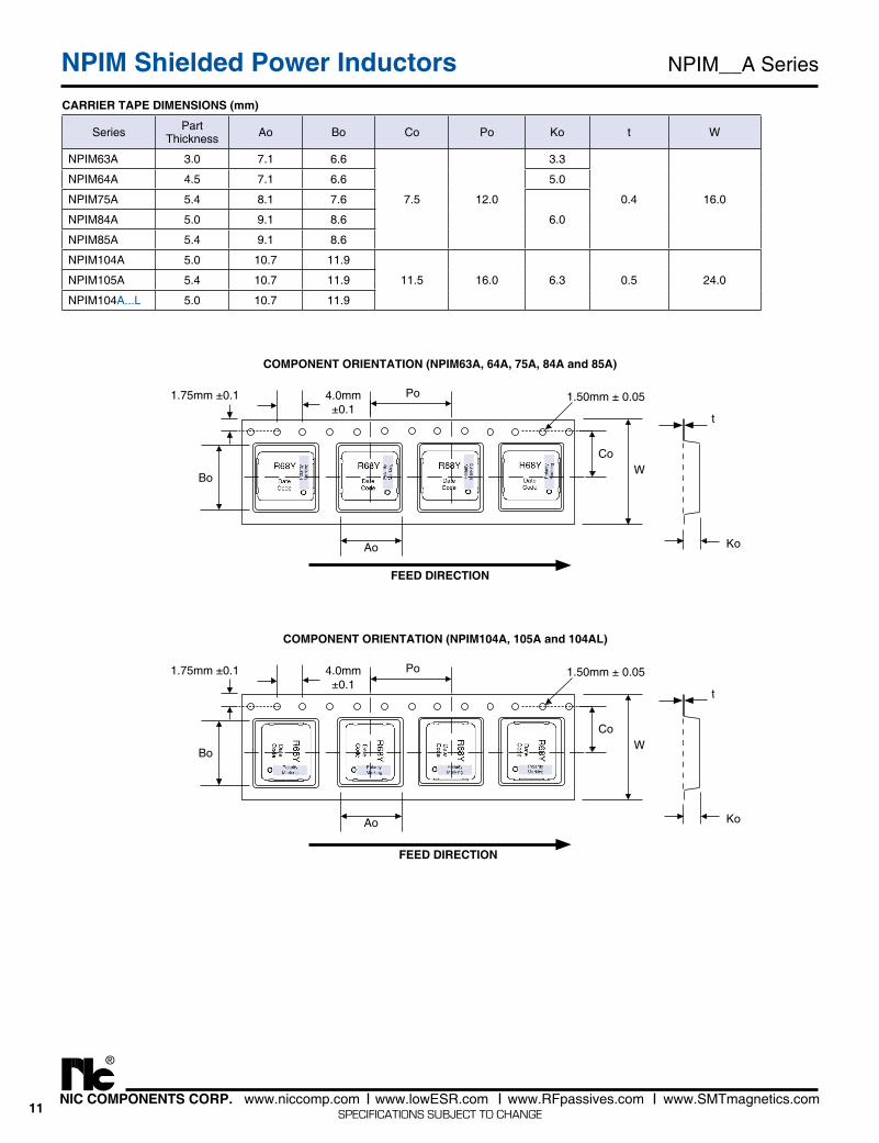
Series Part Thickness Ao Bo Co Po Ko t W
NPIM63A 3.0 7.1 6.6
7.5 12.0
3.3
0.4 16.0
NPIM64A 4.5 7.1 6.6 5.0
NPIM75A 5.4 8.1 7.6
6.0NPIM84A 5.0 9.1 8.6
NPIM85A 5.4 9.1 8.6
NPIM104A 5.0 10.7 11.9
11.5 16.0 6.3 0.5 24.0NPIM105A 5.4 10.7 11.9
NPIM104A...L 5.0 10.7 11.9
CARRIER TAPE DIMENSIONS (mm)
WCo
Ao
Po
Ko
Bo
1.50mm ± 0.054.0mm±0.1
1.75mm ±0.1
t
COMPONENT ORIENTATION (NPIM104A, 105A and 104AL)
FEED DIRECTION
WCo
Ao
Po
Ko
Bo
1.50mm ± 0.054.0mm±0.1
1.75mm ±0.1
t
COMPONENT ORIENTATION (NPIM63A, 64A, 75A, 84A and 85A)
FEED DIRECTION
12NIC COMPONENTS CORP. www.niccomp.com www.lowESR.com www.RFpassives.com www.SMTmagnetics.com
®
SPECIFICATIONS SUBJECT TO CHANGE
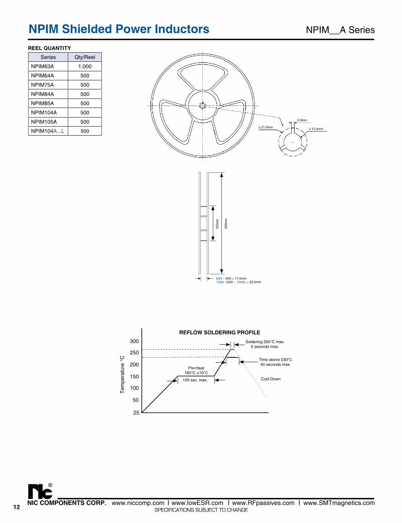
Series Qty/Reel
NPIM63A 1,000
NPIM64A 500
NPIM75A 500
NPIM84A 500
NPIM85A 500
NPIM104A 500
NPIM105A 500
NPIM104A...L 500
100m
m
63A ~ 85A = 17.5mm104A, 105A ~ 104AL = 25.5mm
330m
m
2.0mm
φ 13.0mmφ 21.0mm
REEL QUANTITY
NPIM__A SeriesNPIM Shielded Power Inductors
REFLOW SOLDERING PROFILESoldering 250°C max.
5 seconds max.
Cool Down120 sec. max.
25
50
100
150
200
250
300
Pre-Heat160°C ±10°C
Time above 230°C40 seconds max.
Tem
pera
ture
°C