Foundation Series
8
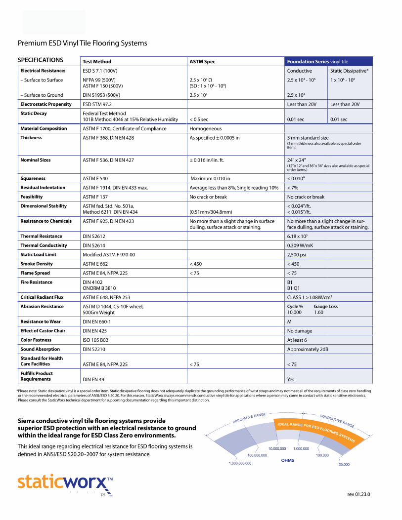
SPECIFICATIONS Foundation Series Premium ESD Vinyl Tile Flooring Systems rev 01.23.0 Test Method ASTM Spec Foundation Series vinyl tile Electrical Resistance: ESD S 7.1 (100V) Conductive Static Dissipative* – Surface to Surface NFPA 99 (500V) ASTM F 150 (500V) 2.5 x 10 4 Ω (SD : 1 x 10 6 - 10 9 ) 2.5 x 10 4 - 10 6 1 x 10 6 - 10 8 – Surface to Ground DIN 51953 (500V) 2.5 x 10 4 2.5 x 10 4 Electrostatic Propensity ESD STM 97.2 Less than 20V Less than 20V Static Decay Federal Test Method 101B Method 4046 at 15% Relative Humidity < 0.5 sec 0.01 sec 0.01 sec Material Composition ASTM F 1700, Certificate of Compliance Homogeneous Thickness ASTM F 368, DIN EN 428 As specified ± 0.0005 in 3 mm standard size (2 mm thickness also available as special order item.) Nominal Sizes ASTM F 536, DIN EN 427 ± 0.016 in/lin. ft. 24" x 24" (12” x 12” and 36” x 36” sizes also available as special order items.) Squareness ASTM F 540 Maximum 0.010 in < 0.010" Residual Indentation ASTM F 1914, DIN EN 433 max. Average less than 8%, Single reading 10% < 7% Feasibility ASTM F 137 No crack or break No crack or break Dimensional Stability ASTM fed. Std. No. 501a, Method 6211, DIN EN 434 (0.51mm/304.8mm) < 0.024"/ft. < 0.015"/ft. Resistance to Chemicals ASTM F 925, DIN EN 423 No more than a slight change in surface dulling, surface attack or staining. No more than a slight change in sur- face dulling, surface attack or staining. Thermal Resistance DIN 52612 6.18 x 10 3 Thermal Conductivity DIN 52614 0.309 W/mK Static Load Limit Modified ASTM F 970-00 2,500 psi Smoke Density ASTM E 662 < 450 < 450 Flame Spread ASTM E 84, NFPA 225 < 75 < 75 Fire Resistance DIN 4102 ONORM B 3810 B1 B1 Q1 Critical Radiant Flux ASTM E 648, NFPA 253 CLASS 1 >1.08W/cm 2 Abrasion Resistance ASTM D 1044, CS-10F wheel, 500Gm Weight Cycle % Gauge Loss 10,000 1.60 Resistance to Wear DIN EN 660-1 M Effect of Castor Chair DIN EN 425 No damage Color Fastness ISO 105 B02 At least 6 Sound Absorption DIN 52210 Approximately 2dB Standard for Health Care Facilities ASTM E 84, NFPA 225 < 75 < 75 Fulfills Product Requirements DIN EN 49 Yes *Please note: Static dissipative vinyl is a special order item. Static dissipative flooring does not adequately duplicate the grounding performance of wrist straps and may not meet all of the requirements of class zero handling or the recommended electrical parameters of ANSI/ESD S 20.20. For this reason, StaticWorx always recommends conductive vinyl tile for applications where a person may come in contact with static sensitive electronics. Please consult the StaticWorx technical department for supporting documentation regarding this important distinction. Sierra conductive vinyl tile flooring systems provide superior ESD protection with an electrical resistance to ground within the ideal range for ESD Class Zero environments. This ideal range regarding electrical resistance for ESD flooring systems is defined in ANSI/ESD S20.20 - 2007 for system resistance.
Transcript of Foundation Series
SPECIFICATIONS
Foundation SeriesPremium ESD Vinyl Tile Flooring Systems
rev 01.23.0
Test Method ASTM Spec Foundation Series vinyl tile
Electrical Resistance: ESD S 7.1 (100V) Conductive Static Dissipative*
– Surface to Surface NFPA 99 (500V) ASTM F 150 (500V)
2.5 x 10⁴ Ω (SD : 1 x 10⁶ - 109)
2.5 x 10⁴ - 106 1 x 10⁶ - 108
– Surface to Ground DIN 51953 (500V) 2.5 x 10⁴ 2.5 x 10⁴
Electrostatic Propensity ESD STM 97.2 Less than 20V Less than 20V
Static Decay Federal Test Method 101B Method 4046 at 15% Relative Humidity < 0.5 sec 0.01 sec 0.01 sec
Material Composition ASTM F 1700, Certificate of Compliance Homogeneous
Thickness ASTM F 368, DIN EN 428 As specified ± 0.0005 in 3 mm standard size (2 mm thickness also available as special order item.)
Nominal Sizes ASTM F 536, DIN EN 427 ± 0.016 in/lin. ft. 24" x 24"(12” x 12” and 36” x 36” sizes also available as special order items.)
Squareness ASTM F 540 Maximum 0.010 in < 0.010"
Residual Indentation ASTM F 1914, DIN EN 433 max. Average less than 8%, Single reading 10% < 7%
Feasibility ASTM F 137 No crack or break No crack or break
Dimensional Stability ASTM fed. Std. No. 501a, Method 6211, DIN EN 434 (0.51mm/304.8mm)
< 0.024"/ft.< 0.015"/ft.
Resistance to Chemicals ASTM F 925, DIN EN 423 No more than a slight change in surface dulling, surface attack or staining.
No more than a slight change in sur-face dulling, surface attack or staining.
Thermal Resistance DIN 52612 6.18 x 10³
Thermal Conductivity DIN 52614 0.309 W/mK
Static Load Limit Modified ASTM F 970-00 2,500 psi
Smoke Density ASTM E 662 < 450 < 450
Flame Spread ASTM E 84, NFPA 225 < 75 < 75
Fire Resistance DIN 4102ONORM B 3810
B1B1 Q1
Critical Radiant Flux ASTM E 648, NFPA 253 CLASS 1 >1.08W/cm2
Abrasion Resistance ASTM D 1044, CS-10F wheel,500Gm Weight
Cycle % Gauge Loss10,000 1.60
Resistance to Wear DIN EN 660-1 M
Effect of Castor Chair DIN EN 425 No damage
Color Fastness ISO 105 B02 At least 6
Sound Absorption DIN 52210 Approximately 2dB
Standard for HealthCare Facilities ASTM E 84, NFPA 225 < 75 < 75
Fulfills ProductRequirements DIN EN 49 Yes
* Please note: Static dissipative vinyl is a special order item. Static dissipative flooring does not adequately duplicate the grounding performance of wrist straps and may not meet all of the requirements of class zero handling or the recommended electrical parameters of ANSI/ESD S 20.20. For this reason, StaticWorx always recommends conductive vinyl tile for applications where a person may come in contact with static sensitive electronics. Please consult the StaticWorx technical department for supporting documentation regarding this important distinction.
Sierra conductive vinyl tile flooring systems provide superior ESD protection with an electrical resistance to ground within the ideal range for ESD Class Zero environments.
This ideal range regarding electrical resistance for ESD flooring systems is defined in ANSI/ESD S20.20 - 2007 for system resistance.
Ashley Delph
Text Box
Ashley Delph
Text Box
Sierra Conductive Vinyl Tile Flooring Distributed by: All-Spec Industries
Ashley Delph
Stamp
Ashley Delph
Text Box
Wilmington, NC 28401
Ashley Delph
Text Box
Phone: 800-537-0351
Ashley Delph
Text Box
Fax: 800-379-9903
Ashley Delph
Text Box
www.all-spec.com
Distributed by: All‐Spec Industries PH: 800‐537‐0351 Email: sales@all‐spec.comWilmington, NC FX: 800‐379‐9903 Web: www.all‐spec.com
1
All‐Spec Industries Phone: 800‐537‐0351 Web: www.all‐spec.com Email: sales@all‐spec.comAll‐Spec Industries Phone: 800‐537‐0351 Web: www.all‐spec.com Email: sales@all‐spec.com
instructions (page 2) as required per specific usewarranty for electrical resistance.
ESD VINYL TILE INSTALLATION INSTRUCTIONSNOTICE TO INSTALLERTHIS DOCUMENT CONTAINS IMPORTANT INSTALLATION AND MAINTENANCE INFORMATION, AS WELL AS CAUTIONS AND
WARNINGS. PLEASE MAKE CERTAIN THESE INSTRUCTIONS ARE PLACED INTO THE HANDS OF THE FLOOR OWNER. THE
SIERRA WARRANTY WILL BECOME EFFECTIVE ONLY IF THESE INSTRUCTIONS ARE FOLLOWED PRECISELY AS WRITTEN. THE
SIERRA EXCLUSIVE WARRANTY LIMITS SIERRA'S LIABILITY TO REPAIR, REPLACE, OR CREDIT, AT THE OPTION OF SIERRA
ON SIERRA PRODUCTS FOR WHICH A CLAIM HAS BEEN MADE ACCORDING TO THE SIERRA CLAIM PROCEDURE.
PLEASE NOTE: ANY CLAIMS RELATED TO SURFACE DEFECTS OR VARIATIONS IN COLOR OR PATTERN MUST BE MADE TO
MADE TO SIERRA PRIOR TO INSTALLATION OF THE MATERIAL. ALL CLAIMS MUST BE IN WRITING.
FOR A COMPLETE STATEMENT OF SIERRA'S EXCLUSIVE WARRANTY, CONTACT:
SIERRA CUSTOMER SERVICE, WILMINGTON, NC 28401; PHONE: 1‐800‐537‐0351 FAX: 1‐800‐379‐9903
WARRANTY ADHESIVESLifetime warranty on static control properties. 1. Flooring Adhesives: Adhere MC Adhesive as5-year warranty that products are free from defects required for specific use.in materials and workmanship, including lifetime 2. Use trowel and roller specified in "Installation"warranty for electrical resistance. instructions (page 2) as required per specific use .
PRODUCTS EXECUTION
ACCEPTABLE MANUFACTURERS EXAMINATIONSIERRA Consult with Sierra Floor Preparation Guide for5228 US HWY 421 N precautions when substrate is lightweightWILMINGTON, NC 28401 aggregate concrete, magnesite flooring, or forPHONE: 1-800-537-0351 below-grade conditions.
1. Verify that concrete sub-floors on or below-gradeFLOOR COVERING MATERIALS are installed over a suitable moisture retardant1. Conductive Resilient Floor Tile: Electrical resistance; membrane.
25,000 - 1,000,000 ohms; Static Dissipative is 2. Ensure concrete floors are dry and exhibit alkalinityavailable upon request. Static dissipative flooring levels between 5 and 9 pH with adequatedoes not meet the recommended system resistance carbonization and no dusting. Maximum moisture-in ANSI / ESD S20.20-2007. emission: 3 lbs./1,000 sq. ft./24 hours.
2. Sierra 24" x 24" tiles, 3.1mm thickness, select colors. 3. Moisture tests are recommended.4. Ensure floor surfaces are smooth and flat with
MANUFACTURING TOLERANCES maximum variation of 1/8 inch in 10 feet.1. Precision Milled 24" x 24" tile to plus or minus 0.002"; 5. Ensure floor surfaces are clean and free from dust,
cut vertical edges perpendicular to tile surface. paint, oil, grease, curing agents, parting compounds,2. Precision control gauge to assure consistent surface surface hardeners, sealers, solvents, old adhesives,
with no high edges. and other extraneous substances.6. Beginning of installation means acceptance of
surface and conditions.
2
All‐Spec Industries Phone: 800‐537‐0351 Web: www.all‐spec.com Email: sales@all‐spec.comAll‐Spec Industries Phone: 800‐537‐0351 Web: www.all‐spec.com Email: sales@all‐spec.com
GROUNDING PROTECTION1. Connect 24" x 2" copper grounding strip, provided Prohibit traffic on finished floor for 48 hours after
by Sierra, to a stranded ground wire. installation.2. Cut off excess and recess in the wall.3. OR: Ground to a column or beam by drilling and CLEANING
tapping the column and attaching the grounding strip 1. Remove excess adhesive from floor, base, and wallto the column in accordance with the Sierra's surfaces without damage, while adhesive is still wet,instructions. using a dilute degreaser or similar cleaning agent.
4. OR: Attach one end of the copper grounding strip 2. Clean floor and base surfaces in accordance withto ground screw on AC electric outlet box. Allow Sierra's instructions.remainder of strip to drop along wall and onto the 3. Buff out dull and/or scratched tiles using single discfloor. buffer with white pad.
5. OR: Screw through drywall and into metal studs ifstruds are connected to building steel. A WORD ABOUT TROWELS:(Copper grounding strip can be covered with wall ONLY use 1/16" notch trowels. Do NOT use a largerbase for a more attractive finished appearance.) notched trowel than the recommended size. An 1/8"
6. Floor MUST be attached to copper grounding strip: trowel will apply 4 times as much adhesive asLay the balance of the grounding strip into the necessary. Excess adhesive can bleed through tileadhesive, covering it with additional adhesive. seams during rolling of installations. Excess adhesiveInstall flooring over the grounding strip. is difficult to remove after it dries.
INSTALLATION1. Install flooring in accordance with Sierra's printed
instructions.2. Use adhesive recommended by Sierra.3. Clean substrate. Spread adhesive evenly in quantity,
as recommended, to ensure adhesion over entirearea of installation.
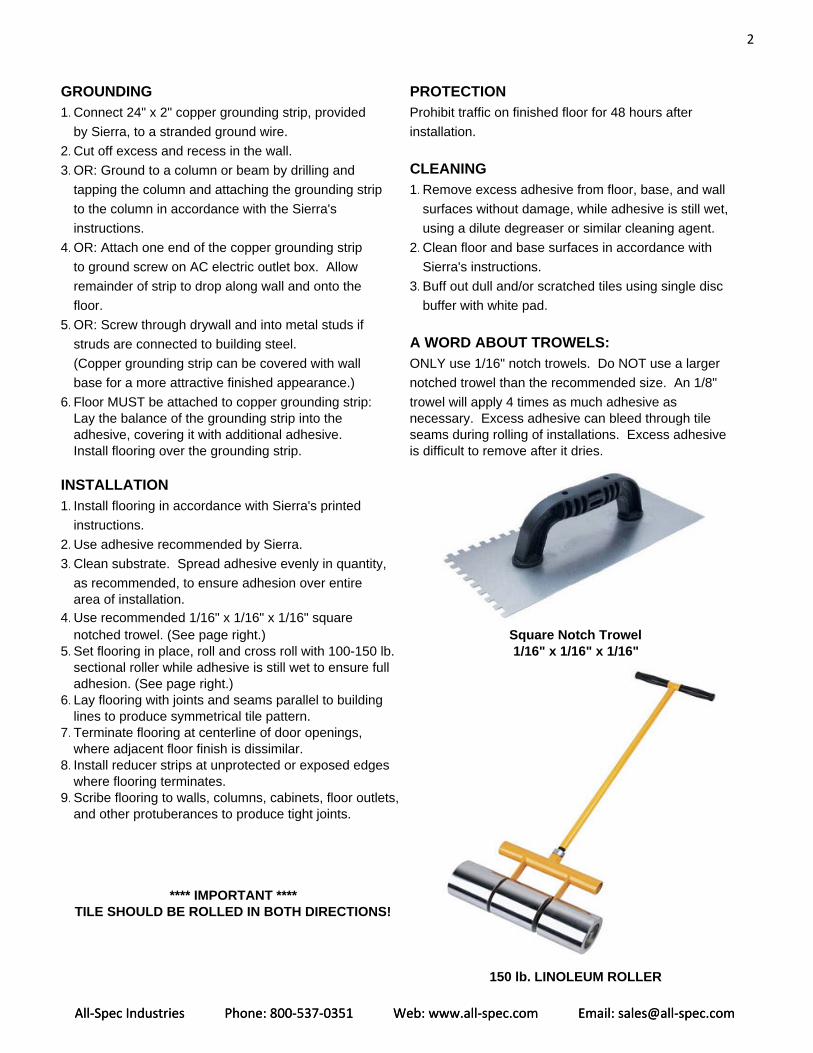
4. Use recommended 1/16" x 1/16" x 1/16" squarenotched trowel. (See page right.) Square Notch Trowel
5. Set flooring in place, roll and cross roll with 100-150 lb. 1/16" x 1/16" x 1/16"sectional roller while adhesive is still wet to ensure fulladhesion. (See page right.)
6. Lay flooring with joints and seams parallel to buildinglines to produce symmetrical tile pattern.
7. Terminate flooring at centerline of door openings,where adjacent floor finish is dissimilar.
8. Install reducer strips at unprotected or exposed edgeswhere flooring terminates.
9. Scribe flooring to walls, columns, cabinets, floor outlets,and other protuberances to produce tight joints.
**** IMPORTANT ****TILE SHOULD BE ROLLED IN BOTH DIRECTIONS!
150 lb. LINOLEUM ROLLER
3
GENERALREFERENCES
• ASTM F-1700: Solid Vinyl Floor Tile • ASTM E-84: Fire Resistance (Stiener Tunnel)• ASTM F-150-98: Electrical Properties • ASTM D-3389: Abrasion Resistance• ANSI / ESD S7.1-2005: Resistive Character- • ASTM D-2240: Hardness
ization of Materials - Floor Materials • ASTM D-2047: Static Coefficient of Friction• ANSI / ASTM FISCO: Electrical Properties • ASTM F-970: Static Load
of Static Control Flooring • ASTM D-297: Density• ANSI / UL 779: Electrically Conductive • ASTM D-412: Tensile
Flooring • ASTM D-412: Elongation• NFPA 99: Standard for Health Care Facilities • ASTM D-624: Tear Die• NFPA 101: Life Safety Code • ASTM F-925: Chemical Resistance• ASTM E-662: Smoke Density • ASTM F-1515: Light Aging• ASTM E-648 / NFPA 253: Fire Resistance • ASTM F-1514: Heat Aging
All‐Spec Industries Phone: 800‐537‐0351 Web: www.all‐spec.com Email: sales@all‐spec.comAll‐Spec Industries Phone: 800‐537‐0351 Web: www.all‐spec.com Email: sales@all‐spec.com
1
All‐Spec Industries Phone: 800‐537‐0351 Web: www.all‐spec.com Email: sales@all‐spec.comAll‐Spec Industries Phone: 800‐537‐0351 Web: www.all‐spec.com Email: sales@all‐spec.com
it out into
Are You Grounded?Instructions for Grounding Conductive and Static Dissipative Flooring
Note: One copper grounding strip should be installed for every 1000 square feet of ESD flooring. Each roomshould have at least one grounding strip.
Conductive and Static Dissipative Flooring can be connected to any ground point.Grounding to an AC electrical outlet is the easiest and most common grounding method.
Caution: Only use electrical receptacles / outlets that have been previously tested using anapproved circuit tester complying with CSA and / or UL standards.
Affixing the Grounding Strip to the Floor
1. Affix the copper grounding strip to the floor by laying the strap into the wet adhesive and extendingit approximately one foot out into the room. approximately one foot the room.
2. Cover the strip with additional adhesive, and then place the tile over the grounding strip. Be surethis area gets rolled when rolling the floor.
3. Leave approximately 10 to 12 inches of grounding strip exposed. This end of the grounding stripwill be attached to the ground point.
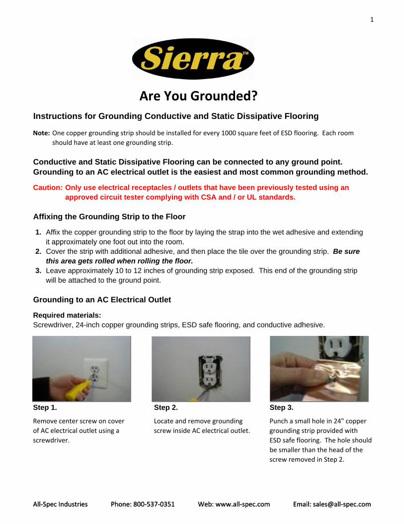
Grounding to an AC Electrical Outlet
Required materials:Screwdriver, 24-inch copper grounding strips, ESD safe flooring, and conductive adhesive.
Step 1. Step 2. Step 3.
Remove center screw on cover Locate and remove grounding Punch a small hole in 24" copperof AC electrical outlet using a screw inside AC electrical outlet. grounding strip provided withscrewdriver. ESD safe flooring. The hole should
be smaller than the head of thescrew removed in Step 2.
2
All‐Spec Industries Phone: 800‐537‐0351 Web: www.all‐spec.com Email: sales@all‐spec.comAll‐Spec Industries Phone: 800‐537‐0351 Web: www.all‐spec.com Email: sales@all‐spec.com
AC outlet cover with screw removed
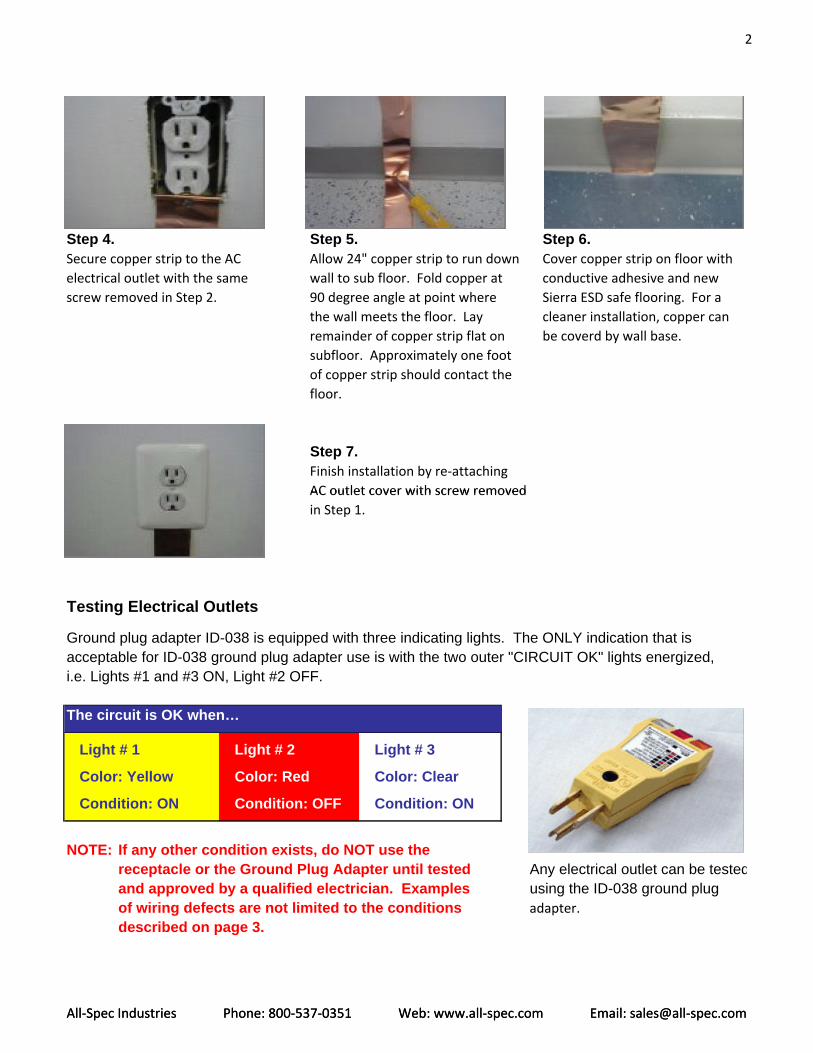
Step 4. Step 5. Step 6.Secure copper strip to the AC Allow 24" copper strip to run down Cover copper strip on floor withelectrical outlet with the same wall to sub floor. Fold copper at conductive adhesive and newscrew removed in Step 2. 90 degree angle at point where Sierra ESD safe flooring. For a
the wall meets the floor. Lay cleaner installation, copper canremainder of copper strip flat on be coverd by wall base.subfloor. Approximately one footof copper strip should contact thefloor.
Step 7.Finish installation by re‐attachingAC outlet cover with screw removed in Step 1.
Testing Electrical Outlets
Ground plug adapter ID-038 is equipped with three indicating lights. The ONLY indication that isacceptable for ID-038 ground plug adapter use is with the two outer "CIRCUIT OK" lights energized,i.e. Lights #1 and #3 ON, Light #2 OFF.
The circuit is OK when…
Light # 1 Light # 2 Light # 3
Color: Yellow Color: Red Color: Clear
Condition: ON Condition: OFF Condition: ON
NOTE: If any other condition exists, do NOT use the receptacle or the Ground Plug Adapter until tested Any electrical outlet can be testedand approved by a qualified electrician. Examples using the ID-038 ground plugof wiring defects are not limited to the conditions adapter.described on page 3.
3
All‐Spec Industries Phone: 800‐537‐0351 Web: www.all‐spec.com Email: sales@all‐spec.comAll‐Spec Industries Phone: 800‐537‐0351 Web: www.all‐spec.com Email: sales@all‐spec.com
Examples of Possible Wiring Defects
1. OPEN GROUND WIRE - The equipment grounding conductor is not complete.
2. REVERSE POLARITY - The hot and the neutral circuit conductors are reversed.
3. OPEN HOT WIRE - The hot circuit conductor is open from a blown fuse, tripped circuit breaker,broken wire, etc.
4. OPEN NEUTRAL WIRE - The neutral circuit conductor is open.
5. HOT AND GROUND REVERSED - The hot circuit conductor and the grounding conductor arereversed.
6. HOT ON NEUTRAL AND HOT OPEN - The hot circuit conductor is connected to neutral terminaland the hot terminal is unwired.
Grounding to a Circuit GroundPrior to installation of the static control flooring, the electrical contractor will tie in a ground wire(#10 or #12) to a convenient ground bus or wall outlet. The wire is then fed down the inside ofthe wall to the floor line where the baseboard meets the floor. Bring the wire through a smallhole in the drywall at the floor line. From here, it can easily be attached to the floor ground. Theexposed end of the copper-grounding strip is then wound together with the ground wire andp pp g g p g gtightened together with the use of a wire nut to securely hold it in place. This connection of thetwo leads is then pushed into the hole in the wall along with the excess wire. There, thebaseboard or wall base will cover it when it is applied to the wall.
Natural Earth GroundIf the floor is being installed on grade or below grade, a copper-grounding rod can be driven intothe ground creating an earth ground for the floor. The 4 or 6 foot ford is driven into the grounduntil only 2 or 3 inches of the rod remains exposed from the floor. The exposed end of thecopper-grounding strip is affixed to the rod using a grounding clamp, usually provided with thegrounding rod. If necessary a piece of #10 or #12 wire can be attached to the grounding rod andrun to the location of the tile grounding strip, where they are then tied together with a wire nut.
Earth GroundIf the building has exposed steel support columns, the grounding strip from the tile can bedirectly grounded to one or more of the columns. Affix the grounding strip to the tile as describedabove. Attach the opposite end of the strip directly to the support column with a grounding screwor use a grounding clamp. Drill a hole in the column and screw the grounding strip directly to the column or mount a grounding clamp to the column and clamp the grounding strip to thecolumn.