SRR1005 Series - Shielded Power Inductors - Bourns · RDC Max. (Ω) I rms Max. (A) I sat Typ. (A)...
3
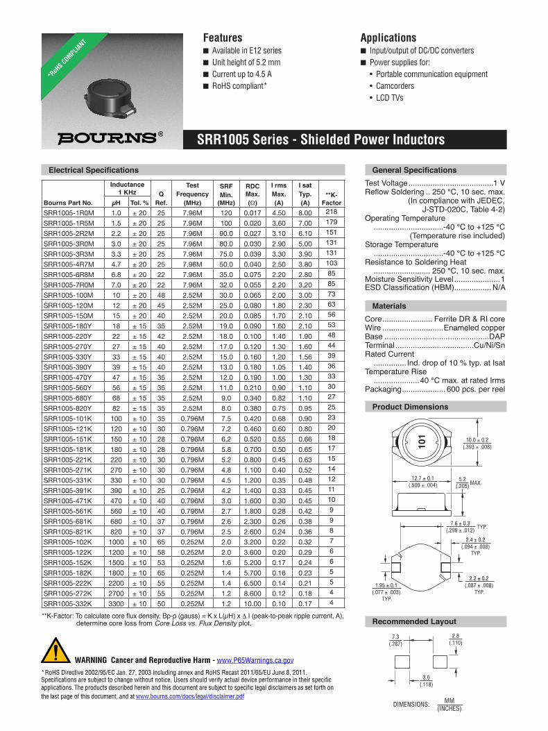
Features ■ Available in E12 series ■ Unit height of 5.2 mm ■ Current up to 4.5 A ■ RoHS compliant* Applications ■ Input/output of DC/DC converters ■ Power supplies for: • Portable communication equipment • Camcorders • LCD TVs SRR1005 Series - Shielded Power Inductors *RoHS COMPLIANT Test Voltage .......................................1 V .. 250 °C, 10 sec. max. (In compliance with JEDEC, J-STD-020C, Table 4-2) Operating Temperature ................................-40 °C to +125 °C (Temperature rise included) Storage Temperature ................................-40 °C to +125 °C Resistance to Soldering Heat .......................... 250 °C, 10 sec. max. Moisture Sensitivity Level ..................... 1 ................. N/A Core ....................... Ferrite DR & RI core Wire ............................ Enameled copper Base ................................................DAP Terminal ....................................Cu/Ni/Sn Rated Current ............... Ind. drop of 10 % typ. at Isat Temperature Rise ..................... 40 °C max. at rated Irms Packaging .................... 600 pcs. per reel Materials Product Dimensions DIMENSIONS: MM (INCHES) Δ I (peak-to-peak ripple current, A), determine core loss from Core Loss vs. Flux Density plot. Bourns Part No. Inductance 1 KHz Q Ref. Test Frequency (MHz) SRF Min. (MHz) RDC Max. (Ω) I rms Max. (A) I sat Typ. (A) **K- Factor μH Tol. % SRR1005-1R0M 1.0 ± 20 25 7.96M 120 0.017 4.50 8.00 218 SRR1005-1R5M 1.5 ± 20 25 7.96M 100 0.020 3.60 7.00 179 SRR1005-2R2M 2.2 ± 20 25 7.96M 90.0 0.027 3.10 6.10 151 SRR1005-3R0M 3.0 ± 20 25 7.96M 80.0 0.030 2.90 5.00 131 SRR1005-3R3M 3.3 ± 20 25 7.96M 75.0 0.039 3.30 3.90 131 SRR1005-4R7M 4.7 ± 20 25 7.96M 50.0 0.040 2.50 3.80 103 SRR1005-6R8M 6.8 ± 20 22 7.96M 35.0 0.075 2.20 2.80 85 SRR1005-7R0M 7.0 ± 20 22 7.96M 32.0 0.055 2.20 3.20 85 SRR1005-100M 10 ± 20 48 2.52M 30.0 0.065 2.00 3.00 73 SRR1005-120M 12 ± 20 45 2.52M 25.0 0.080 1.80 2.30 63 SRR1005-150M 15 ± 20 40 2.52M 20.0 0.085 1.70 2.10 56 SRR1005-180Y 18 ± 15 35 2.52M 19.0 0.090 1.60 2.10 53 SRR1005-220Y 22 ± 15 42 2.52M 18.0 0.100 1.40 1.90 48 SRR1005-270Y 27 ± 15 40 2.52M 17.0 0.120 1.30 1.60 44 SRR1005-330Y 33 ± 15 40 2.52M 15.0 0.160 1.20 1.56 39 SRR1005-390Y 39 ± 15 40 2.52M 13.0 0.180 1.05 1.40 36 SRR1005-470Y 47 ± 15 35 2.52M 12.0 0.190 1.00 1.30 33 SRR1005-560Y 56 ± 15 35 2.52M 11.0 0.210 0.90 1.10 30 SRR1005-680Y 68 ± 15 35 2.52M 9.0 0.340 0.82 1.10 27 SRR1005-820Y 82 ± 15 35 2.52M 8.0 0.380 0.75 0.95 25 SRR1005-101K 100 ± 10 35 0.796M 7.5 0.420 0.68 0.90 23 SRR1005-121K 120 ± 10 30 0.796M 7.2 0.460 0.60 0.80 20 SRR1005-151K 150 ± 10 28 0.796M 6.2 0.520 0.55 0.66 18 SRR1005-181K 180 ± 10 28 0.796M 5.8 0.700 0.50 0.65 17 SRR1005-221K 220 ± 10 30 0.796M 5.2 0.800 0.45 0.63 15 SRR1005-271K 270 ± 10 30 0.796M 4.8 1.100 0.40 0.52 14 SRR1005-331K 330 ± 10 30 0.796M 4.5 1.200 0.35 0.48 12 SRR1005-391K 390 ± 10 25 0.796M 4.2 1.400 0.33 0.45 11 SRR1005-471K 470 ± 10 40 0.796M 3.0 1.600 0.30 0.45 10 SRR1005-561K 560 ± 10 40 0.796M 2.7 1.800 0.28 0.42 9 SRR1005-681K 680 ± 10 37 0.796M 2.6 2.300 0.26 0.38 9 SRR1005-821K 820 ± 10 37 0.796M 2.5 2.600 0.24 0.36 8 SRR1005-102K 1000 ± 10 65 0.252M 2.0 3.200 0.22 0.32 7 SRR1005-122K 1200 ± 10 58 0.252M 2.0 3.600 0.20 0.29 6 SRR1005-152K 1500 ± 10 53 0.252M 1.6 5.200 0.17 0.24 6 SRR1005-182K 1800 ± 10 65 0.252M 1.4 5.700 0.16 0.23 5 SRR1005-222K 2200 ± 10 55 0.252M 1.4 6.500 0.14 0.21 5 SRR1005-272K 2700 ± 10 55 0.252M 1.2 8.600 0.12 0.18 4 SRR1005-332K 3300 ± 10 50 0.252M 1.2 10.00 0.10 0.17 4 Recommended Layout 7.3 (.287) 12.7 ± 0.1 (.500 ± .004) 3.0 (.118) 5.2 (.205) MAX. 10.0 ± 0.2 (.393 ± .008) 2.8 (.110) 101 TYP. TYP. 7.6 ± 0.3 (.299 ± .012) 2.4 ± 0.2 (.094 ± .008) TYP. 2.2 ± 0.2 (.087 ± .008) TYP. 1.95 ± 0.1 (.077 ± .003) * RoHS Directive 2002/95/EC Jan. 27, 2003 including annex and RoHS Recast 2011/65/EU June 8, 2011. WARNING Cancer and Reproductive Harm - www.P65Warnings.ca.gov Specifications are subject to change without notice. Users should verify actual device performance in their specific applications. The products described herein and this document are subject to specific legal disclaimers as set forth on the last page of this document, and at www.bourns.com/docs/legal/disclaimer.pdf
-
Upload
nguyenphuc -
Category
Documents
-
view
216 -
download
0
Transcript of SRR1005 Series - Shielded Power Inductors - Bourns · RDC Max. (Ω) I rms Max. (A) I sat Typ. (A)...
Features■ Available in E12 series■ Unit height of 5.2 mm■ Current up to 4.5 A■ RoHS compliant*
Applications■ Input/output of DC/DC converters■ Power supplies for: • Portable communication equipment • Camcorders • LCD TVs
SRR1005 Series - Shielded Power Inductors
*RoH
S COMPLIANT
LEAD FR
EE
LEAD FR
EE
VERSIO
NS ARE
RoHS COMPLIA
NT*Test Voltage .......................................1 V
.. 250 °C, 10 sec. max. (In compliance with JEDEC, J-STD-020C, Table 4-2)Operating Temperature ................................-40 °C to +125 °C (Temperature rise included)Storage Temperature ................................-40 °C to +125 °CResistance to Soldering Heat .......................... 250 °C, 10 sec. max.Moisture Sensitivity Level .....................1
................. N/A
Core ....................... Ferrite DR & RI coreWire ............................Enameled copperBase ................................................DAPTerminal ....................................Cu/Ni/SnRated Current ............... Ind. drop of 10 % typ. at IsatTemperature Rise .....................40 °C max. at rated IrmsPackaging .................... 600 pcs. per reel
Materials
Product Dimensions
DIMENSIONS: MM (INCHES)
Δ I (peak-to-peak ripple current, A), determine core loss from Core Loss vs. Flux Density plot.
Bourns Part No.
Inductance 1 KHz Q
Ref.
TestFrequency
(MHz)
SRFMin.
(MHz)
RDC Max.(Ω)
I rmsMax.(A)
I satTyp.(A)
**K- FactorµH Tol. %
SRR1005-1R0M 1.0 ± 20 25 7.96M 120 0.017 4.50 8.00 218SRR1005-1R5M 1.5 ± 20 25 7.96M 100 0.020 3.60 7.00 179SRR1005-2R2M 2.2 ± 20 25 7.96M 90.0 0.027 3.10 6.10 151SRR1005-3R0M 3.0 ± 20 25 7.96M 80.0 0.030 2.90 5.00 131SRR1005-3R3M 3.3 ± 20 25 7.96M 75.0 0.039 3.30 3.90 131SRR1005-4R7M 4.7 ± 20 25 7.96M 50.0 0.040 2.50 3.80 103SRR1005-6R8M 6.8 ± 20 22 7.96M 35.0 0.075 2.20 2.80 85SRR1005-7R0M 7.0 ± 20 22 7.96M 32.0 0.055 2.20 3.20 85SRR1005-100M 10 ± 20 48 2.52M 30.0 0.065 2.00 3.00 73SRR1005-120M 12 ± 20 45 2.52M 25.0 0.080 1.80 2.30 63SRR1005-150M 15 ± 20 40 2.52M 20.0 0.085 1.70 2.10 56SRR1005-180Y 18 ± 15 35 2.52M 19.0 0.090 1.60 2.10 53SRR1005-220Y 22 ± 15 42 2.52M 18.0 0.100 1.40 1.90 48SRR1005-270Y 27 ± 15 40 2.52M 17.0 0.120 1.30 1.60 44SRR1005-330Y 33 ± 15 40 2.52M 15.0 0.160 1.20 1.56 39SRR1005-390Y 39 ± 15 40 2.52M 13.0 0.180 1.05 1.40 36SRR1005-470Y 47 ± 15 35 2.52M 12.0 0.190 1.00 1.30 33SRR1005-560Y 56 ± 15 35 2.52M 11.0 0.210 0.90 1.10 30SRR1005-680Y 68 ± 15 35 2.52M 9.0 0.340 0.82 1.10 27SRR1005-820Y 82 ± 15 35 2.52M 8.0 0.380 0.75 0.95 25SRR1005-101K 100 ± 10 35 0.796M 7.5 0.420 0.68 0.90 23SRR1005-121K 120 ± 10 30 0.796M 7.2 0.460 0.60 0.80 20SRR1005-151K 150 ± 10 28 0.796M 6.2 0.520 0.55 0.66 18SRR1005-181K 180 ± 10 28 0.796M 5.8 0.700 0.50 0.65 17SRR1005-221K 220 ± 10 30 0.796M 5.2 0.800 0.45 0.63 15SRR1005-271K 270 ± 10 30 0.796M 4.8 1.100 0.40 0.52 14SRR1005-331K 330 ± 10 30 0.796M 4.5 1.200 0.35 0.48 12SRR1005-391K 390 ± 10 25 0.796M 4.2 1.400 0.33 0.45 11SRR1005-471K 470 ± 10 40 0.796M 3.0 1.600 0.30 0.45 10SRR1005-561K 560 ± 10 40 0.796M 2.7 1.800 0.28 0.42 9SRR1005-681K 680 ± 10 37 0.796M 2.6 2.300 0.26 0.38 9SRR1005-821K 820 ± 10 37 0.796M 2.5 2.600 0.24 0.36 8SRR1005-102K 1000 ± 10 65 0.252M 2.0 3.200 0.22 0.32 7SRR1005-122K 1200 ± 10 58 0.252M 2.0 3.600 0.20 0.29 6SRR1005-152K 1500 ± 10 53 0.252M 1.6 5.200 0.17 0.24 6SRR1005-182K 1800 ± 10 65 0.252M 1.4 5.700 0.16 0.23 5SRR1005-222K 2200 ± 10 55 0.252M 1.4 6.500 0.14 0.21 5SRR1005-272K 2700 ± 10 55 0.252M 1.2 8.600 0.12 0.18 4SRR1005-332K 3300 ± 10 50 0.252M 1.2 10.00 0.10 0.17 4
Recommended Layout
7.3(.287)
12.7 ± 0.1(.500 ± .004)
3.0(.118)
5.2(.205) MAX.
10.0 ± 0.2(.393 ± .008)
2.8(.110)
101
TYP.
TYP.
7.6 ± 0.3(.299 ± .012)
2.4 ± 0.2(.094 ± .008)
TYP.
2.2 ± 0.2(.087 ± .008)
TYP.
1.95 ± 0.1(.077 ± .003)
* RoHS Directive 2002/95/EC Jan. 27, 2003 including annex and RoHS Recast 2011/65/EU June 8, 2011.
WARNING Cancer and Reproductive Harm - www.P65Warnings.ca.gov
Specifications are subject to change without notice. Users should verify actual device performance in their specific applications. The products described herein and this document are subject to specific legal disclaimers as set forth onthe last page of this document, and at www.bourns.com/docs/legal/disclaimer.pdf

SRR1005 Series - Shielded Power Inductors
Soldering Profile
0
50
100
150
200
250
300
50 0 100 150 200 250 300
Time (seconds)
Tem
pera
tur e
(°
C)
<2> Max. of 30 seconds > 220 °C<1> Max. of 10 seconds at 250 °C
250 °C
<2>
<1>
120 - 150 seconds
Ramp-up4 °/second maximum
Ramp-down5 °C/second maximum
Core Loss vs. Flux Density
Flux Density Bp-p (gauss)
10
100
1000
0.10
1
10 10001000.01
Core
Los
s (m
W) 1 MHz
800 KHz500 KHz400 KHz300 KHz200 KHz100 KHz
Schematic
Specifications are subject to change without notice.Users should verify actual device performance in their specific applications. The products described herein and this document are subject to specific legal disclaimers as set forth on the last page of this document, and at www.bourns.com/docs/legal/disclaimer.pdf.
Legal Disclaimer Notice
This legal disclaimer applies to purchasers and users of Bourns® products manufactured by or on behalf of Bourns, Inc. and
Unless otherwise expressly indicated in writing, Bourns® products and data sheets relating thereto are subject to change
and complete before placing orders for Bourns® products.
The characteristics and parameters of a Bourns® product set forth in its data sheet are based on laboratory conditions, and statements regarding the suitability of products for certain types of applications are based on Bourns’ knowledge of typical requirements in generic applications. The characteristics and parameters of a Bourns®
® product with other components ®
the actual performance of the Bourns®
® product as meeting the requirements of a particular industry
®
of Bourns® products are responsible for ensuring compliance with safety-related requirements and standards applicable to
Bourns®
on a case-by-case basis, use of any Bourns®
®
®
®
®
Bourns®
® standard products that are suitable for use in aircraft
® standard
the user’s sole risk.
® custom products shall be negotiated on a case-by-case basis by Bourns and the user for which such Bourns®
® standard products shall also apply to such Bourns® custom products.
Users shall not sell, transfer, export or re-export any Bourns®
Bourns®
® products and Bourns technology and technical data may not under any circumstance be
exported or re-exported to countries subject to international sanctions or embargoes. Bourns® products may not, without
bilingual versions are available at: Web Page: http://www.bourns.com/legal/disclaimers-terms-and-policies PDF: http://www.bourns.com/docs/Legal/disclaimer.pdf