New product Capacitance type electromagnetic flow sensor
12
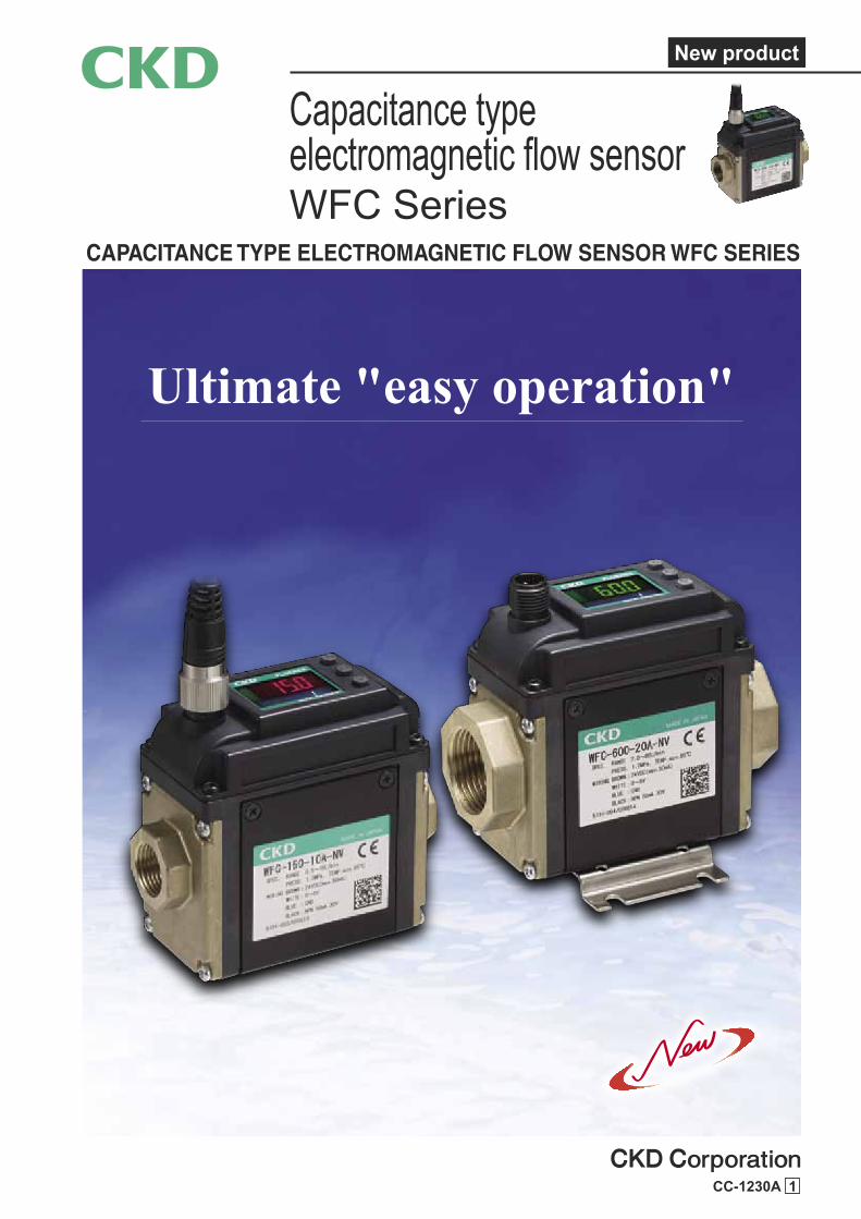
CC-1230A 1 Capacitance type electromagnetic flow sensor WFC Series CAPACITANCE TYPE ELECTROMAGNETIC FLOW SENSOR WFC SERIES New product Ultimate "easy operation"
Transcript of New product Capacitance type electromagnetic flow sensor
CC-1230A 1
Capacitance type electromagnetic flow sensorWFC Series
CAPACITANCE TYPE ELECTROMAGNETIC FLOW SENSOR WFC SERIES
New product
Ultimate "easy operation"
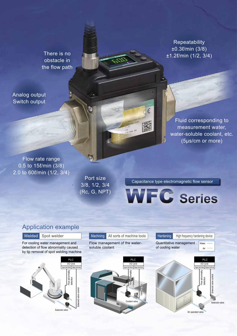
There is noobstacle in
the flow path
Analog outputSwitch output
Repeatability±0.3ℓ/min (3/8)
±1.2ℓ/min (1/2, 3/4)
Flow rate range0.5 to 15ℓ/min (3/8)
2.0 to 60ℓ/min (1/2, 3/4)Port size
3/8, 1/2, 3/4(Rc, G, NPT)
Fluid corresponding tomeasurement water,
water-soluble coolant, etc.(5μs/cm or more)
Flow sensor of through structure
Throughstructure
Non-contactwith fluid
Straightpipe section
unnecessary
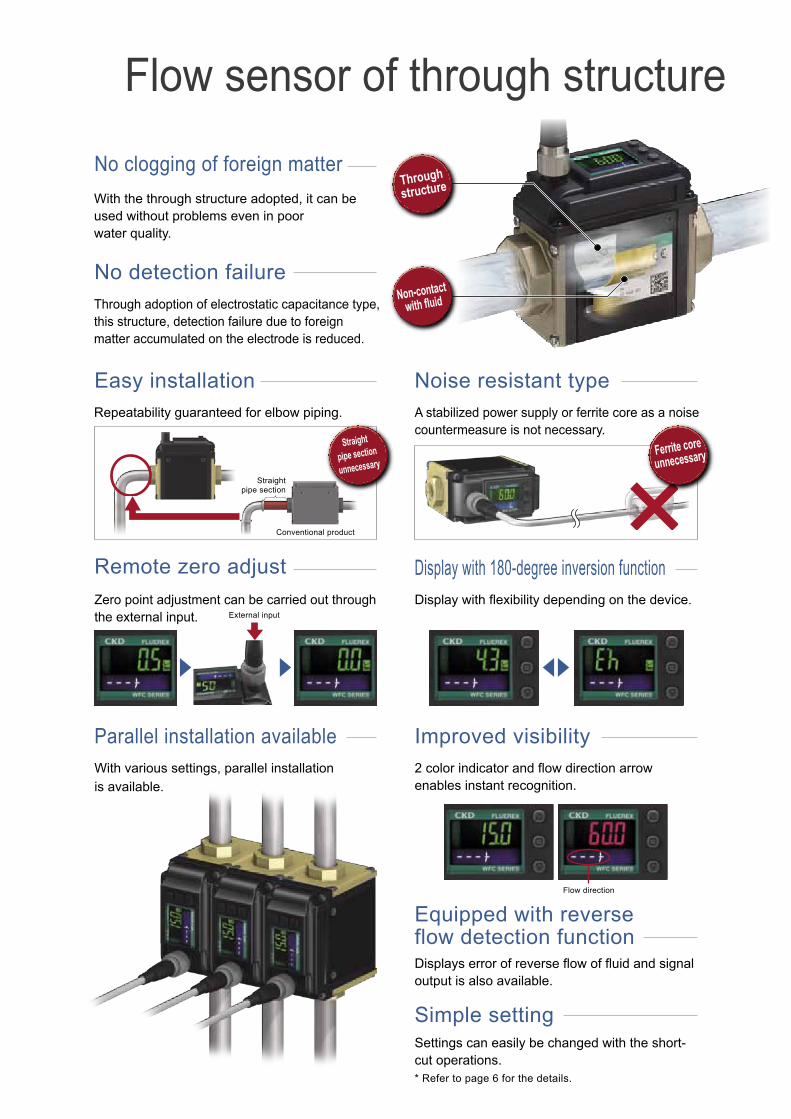
With the through structure adopted, it can beused without problems even in poor water quality.
Ferrite coreunnecessary
Through adoption of electrostatic capacitance type, this structure, detection failure due to foreign matter accumulated on the electrode is reduced.
Repeatability guaranteed for elbow piping. A stabilized power supply or ferrite core as a noisecountermeasure is not necessary.
Noise resistant typeEasy installation
No detection failure
No clogging of foreign matter
Display with flexibility depending on the device.
Display with 180-degree inversion functionZero point adjustment can be carried out through the external input.
Remote zero adjust
External input
Flow direction
Conventional product
Straightpipe section
2 color indicator and flow direction arrow enables instant recognition.
Improved visibilityWith various settings, parallel installationis available.
Parallel installation available
Displays error of reverse flow of fluid and signaloutput is also available.
Equipped with reverse flow detection function
Settings can easily be changed with the short-cut operations.* Refer to page 6 for the details.
Simple setting
Capacitance type electromagnetic flow sensor
Application example
For cooling water management anddetection of flow abnormality causedby tip removal of spot welding machine
Flow management of the water-soluble coolant
Quantitative management of cooling water
Welded Spot welder Machining All sorts of machine tools Hardening High frequency hardening device
Water
I/O UnitI/O Unit
Air
PLCPLCI/O Unit
Input terminal Output terminal Input terminal Output terminal Input terminal Output terminal
PLC
Flow
abn
orm
ality
dete
ction
Flow
abn
orm
ality
dete
ction
Solen
oid va
lve co
ntro
l
Solen
oid va
lve co
ntro
l
Flow
abn
orm
ality
dete
ction
Flow
abn
orm
ality
dete
ction
Valve
cont
rol
Valve
cont
rol
Solenoid valve
Coolant valve
Air operated valve
Solenoid valve
There is noobstacle in
the flow path
Analog outputSwitch output
Repeatability±0.3ℓ/min (3/8)
±1.2ℓ/min (1/2, 3/4)
Flow rate range0.5 to 15ℓ/min (3/8)
2.0 to 60ℓ/min (1/2, 3/4)Port size
3/8, 1/2, 3/4(Rc, G, NPT)
Fluid corresponding tomeasurement water,
water-soluble coolant, etc.(5μs/cm or more)
Flow sensor of through structure
Throughstructure
Non-contactwith fluid
Straightpipe section
unnecessary
With the through structure adopted, it can beused without problems even in poor water quality.
Ferrite coreunnecessary
Through adoption of electrostatic capacitance type, this structure, detection failure due to foreign matter accumulated on the electrode is reduced.
Repeatability guaranteed for elbow piping. A stabilized power supply or ferrite core as a noisecountermeasure is not necessary.
Noise resistant typeEasy installation
No detection failure
No clogging of foreign matter
Display with flexibility depending on the device.
Display with 180-degree inversion functionZero point adjustment can be carried out through the external input.
Remote zero adjust
External input
Flow direction
Conventional product
Straightpipe section
2 color indicator and flow direction arrow enables instant recognition.
Improved visibilityWith various settings, parallel installationis available.
Parallel installation available
Displays error of reverse flow of fluid and signaloutput is also available.
Equipped with reverse flow detection function
Settings can easily be changed with the short-cut operations.* Refer to page 6 for the details.
Simple setting
Capacitance type electromagnetic flow sensor
Application example
For cooling water management anddetection of flow abnormality causedby tip removal of spot welding machine
Flow management of the water-soluble coolant
Quantitative management of cooling water
Welded Spot welder Machining All sorts of machine tools Hardening High frequency hardening device
Water
I/O UnitI/O Unit
Air
PLCPLCI/O Unit
Input terminal Output terminal Input terminal Output terminal Input terminal Output terminal
PLC
Flow
abn
orm
ality
dete
ction
Flow
abn
orm
ality
dete
ction
Solen
oid va
lve co
ntro
l
Solen
oid va
lve co
ntro
l
Flow
abn
orm
ality
dete
ction
Flow
abn
orm
ality
dete
ction
Valve
cont
rol
Valve
cont
rol
Solenoid valve
Coolant valve
Air operated valve
Solenoid valve
1
Capacitance type electromagnetic flow sensor
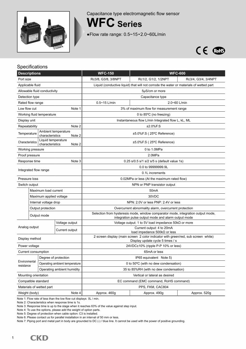
WFC Series●Flow rate range: 0.5~15•2.0~60L/min
SpecificationsDescriptions WFC-150 WFC-600Port size Rc3/8, G3/8, 3/8NPT Rc1/2, G1/2, 1/2NPT Rc3/4, G3/4, 3/4NPT
Applicable fluid Liquid (conductive liquid) that will not corrode the water or materials of wetted part
Allowable fluid conductivity 5μS/cm or more
Detection type Capacitance type
Rated flow range 0.5~15 L/min 2.0~60 L/min
Low flow cut Note 1 3% of maximum flow for measurement range
Working fluid temperature 0 to 85ºC (no freezing)
Display unit Instantaneous flow L/min Integrated flow L, kL, ML
Repeatability Note 2 ±2.0%F.S
Temperature Ambient temperature characteristics Note 2 ±5.0%F.S ( 25ºC Reference)
Characteristics Liquid temperature characteristics Note 2 ±5.0%F.S ( 25ºC Reference)
Working pressure 0 to 1.0MPa
Proof pressure 2.0MPa
Response time Note 3 0.25 s/0.5 s/1 s/2 s/5 s (default value 1s)
Integrated flow range0.0 to 99999999.9L
0.1L increments
Pressure loss 0.02MPa or less (At the maximum rated flow)
Switch output NPN or PNP transistor output
Maximum load current 50mA
Maximum applied voltage 30VDC
Internal voltage drop NPN: 2.0V or less PNP: 2.4V or less
Output protection Overcurrent abnormality alarm, overcurrent protection
Output mode Selection from hysteresis mode, window comparator mode, integration output mode, integration pulse output mode and alarm output mode
Analog outputVoltage output Voltage output: 1 to 5V load impedance 50kΩ or more
Current output Current output: 4 to 20mAload impedance 500kΩ or less
Display method 2 screen display (main screen 2 color indicator with green/red, sub screen white)Display update cycle 5 times / s
Power voltage 24VDC±10% (ripple P-P 10% or less)
Current consumption 65mA or less
Environmental resistance
Degree of protection IP65 equivalent Note 5)
Operating ambient temperature 0 to 50ºC (with no dew condensation)
Operating ambient humidity 35 to 85%RH (with no dew condensation)
Mounting orientation Vertical or lateral as desired
Compatible standard EC command (EMC command, RoHS command)
Materials of wetted part PPS, FKM, CAC804
Weight (body) Note 4 Approx. 460g Approx. 490g Approx. 520g
Note 1: Flow rate of less than the low flow cut displays 0L / min.Note 2: Characteristics when response time is 1s.Note 3: Response time is up to the stage when it reaches 63% of the value against step input.Note 4: To use the options, please add the weight of option parts.Note 5: Degree of protection when cable option: C3 is installed.Note 6: Please contact us for parallel installation in an interval of 50 mm or less.Note 7: Piping port and metal part in body are grounded to DC (-) / blue line. It cannot be used with the power of positive grounding.
2
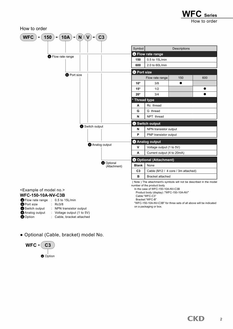
How to orderWFC Series
How to order
Symbol Descriptions
a Flow rate range150 0.5 to 15L/min
600 2.0 to 60L/min
b Port sizeFlow rate range 150 600
10* 3/8
15* 1/2
20* 3/4
* Thread typeA Rc thread
G G thread
N NPT thread
c Switch outputN NPN transistor output
P PNP transistor output
d Analog outputV Voltage output (1 to 5V)
A Current output (4 to 20mA)
e Optional (Attachment)Blank None
C3 Cable (M12 / 4 core / 3m attached)
B Bracket attached
( Note ) The attachment's symbols will not be described in the model number of the product body. In the case of WFC-150-10A-NV-C3B Product body (display) :"WFC-150-10A-NV" Cable:“WFC-C3” Bracket:“WFC-B”
"WFC-150-10A-NV-C3B" for three sets of all above will be indicated on a packaging or box.
<Example of model no.>WFC-150-10A-NV-C3B
a Flow rate range : 0.5 to 15L/minb Port size : Rc3/8c Switch output : NPN transistor outputd Analog output : Voltage output (1 to 5V)e Option : Cable, bracket attached
c Switch output
d Analog output
e Optional (Attachment)
b Port size
WFC 150 10A N V C3
a Flow rate range
● Optional (Cable, bracket) model No.
e Option
C3WFC
3
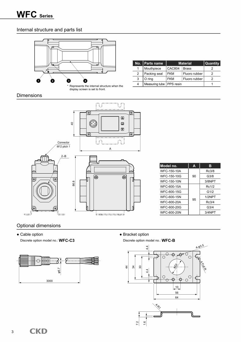
WFC Series
Internal structure and parts list
No. Parts name Material Quantity1 Mouthpiece CAC804 Brass 22 Packing seal FKM Fluoro rubber 23 O ring FKM Fluoro rubber 24 Measuring tube PPS resin 1
Dimensions
Optional dimensions
Model no. A BWFC-150-10A
90Rc3/8
WFC-150-10G G3/8WFC-150-10N 3/8NPTWFC-600-15A
95
Rc1/2WFC-600-15G G1/2WFC-600-15N 1/2NPTWFC-600-20A Rc3/4WFC-600-20G G3/4WFC-600-20N 3/4NPT
● Cable option Discrete option model no.: WFC-C3
● Bracket option Discrete option model no.: WFC-B
* Represents the internal structure when the display screen is set to front.
1 2 3 4
3000
10
5664
4-φ3.5
φ22
4 Full R
4-R1
φ6.7 30
4.4
4.4
1.6
7.2
3444
86.8
40
ConnectorM12 pitch 1
2–B
A
4
Wiring methodWFC Series
••• Connect to the DC power supply minus [-] : 0VDC
••• Switch output (PNP) : MAX.30VDC 50mA
••• Analog output/switch input :
••• Analog output/switch input :
••• Connect to the DC power supply plus [+] : 24VDC±10%
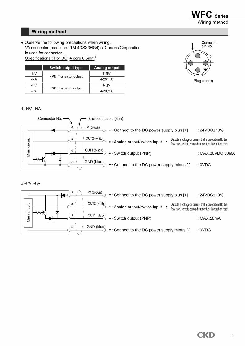
● Observe the following precautions when wiring.VA connector (model no.: TM-4DSX3HG4) of Correns Corporation is used for connector.Specifications : For DC, 4 core 0.5mm2
1)-NV, -NA
Wiring method
Plug (male)
Connector pin No.
2
1
4
3
Connector No. Enclosed cable (3 m)
GND (blue)
OUT1 (black)
OUT2 (white)
+V (brown)
Mai
n ci
rcui
t
○1
○4
○3
○2
••• Connect to the DC power supply minus [-] : 0VDC
••• Switch output (PNP) : MAX.50mA
••• Connect to the DC power supply plus [+] : 24VDC±10%
2)-PV, -PA
GND (blue)
OUT1 (black)
OUT2 (white)
+V (brown)○1
○4
○3
○2
Switch output type Analog output-NV
NPN Transistor output1-5[V]
-NA 4-20[mA]
-PVPNP Transistor output
1-5[V]
-PA 4-20[mA]
Mai
n ci
rcui
t
Outputs a voltage or current that is proportional to the flow rate / remote zero adjustment, or integration reset
Outputs a voltage or current that is proportional to the flow rate / remote zero adjustment, or integration reset
5
WFC Series
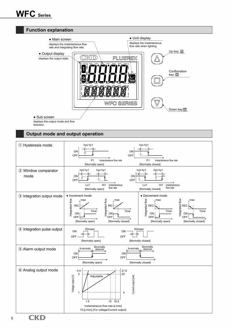
displays the output mode and flow direction.
● Sub screen
displays the output state.
displays the instantaneous flow rate and integrating flow rate.
displays the instantaneous flow rate when lighting.
Up key:
Confirmation key:
Down key:
● Output display
● Main screen ● Unit display
Function explanation
Output mode and output operation
① Hysteresis mode
④ Integration pulse output
⑤ Alarm output mode
⑥ Analog output mode
② Window comparator mode
③ Integration output mode ● Decrement mode● Increment mode
Volta
ge o
utpu
t [V]
hys hy1
50msec
No abnormality No abnormalityAbnormality observed
Abnormality observed
50msec
hys hy1
INC DECINC DEC
hys hy1hys hy1 hys hy1
hys hy1
Instantaneous flow rate
Instantaneous flow rate
Inte
grat
ed fl
ow
Inte
grat
ed fl
ow
Inte
grat
ed fl
ow
Inte
grat
ed fl
ow
Instantaneous flow rate
Instantaneous flow rate[Normally open]
[Normally open]
[Normally open] [Normally open]
[Normally open]
[Normally open]
Adjustable
Instantaneous flow rate [L/min]15 [L/min] (For voltage/Current output)
1.5 15 16.5
[Normally closed]
[Normally closed]
[Normally closed] [Normally closed]
[Normally closed]
[Normally closed]
P1
Lo1
Time TimeTime Time
Lo1Hi1
max maxmax max
Hi1
P1
ON
ON
ON ON
ON
ON
ON ONON ON
ON
ONOFF
OFF
OFF OFF
OFF
OFF
OFF
5.4 21.65 20
1 4
OFFOFF OFF
OFF
OFF
Curre
nt o
utpu
t [m
A]
6
Functional explanationWFC Series
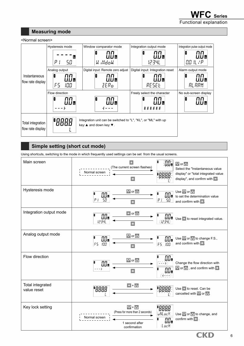
Measuring mode
Simple setting (short cut mode)
<Normal screen>
Using shortcuts, switching to the mode in which frequently used settings can be set from the usual screens.
Instantaneous flow rate display
Total integration flow rate display
Main screen or Select the "Instantaneous value display" or "total integrated value display", and confirm with .
Use or to change, and confirm with .
Use or to set the determination value and confirm with .
Use to reset integrated value.
Use or to change F.S., and confirm with .
Use to reset. Can be cancelled with or .
Change the flow direction with or , and confirm with .
(The current screen flashes)
+ (Press for more than 2 seconds)
1 second after confirmation
+
or
or
or
or
Normal screen
Normal screen
Hysteresis mode
Integration output mode
Analog output mode
Flow direction
Total integrated value reset
Key lock setting
Integration unit can be switched to "L", "KL", or "ML" with up key:▲ and down key:▼.
Hysteresis mode
Analog output
Flow direction
Window comparator mode
Digital input: Remote zero adjust
Integration output mode
Digital input: Integration reset
Freely select the character
Integration pulse output mode
Alarm output mode
No sub-screen display
7
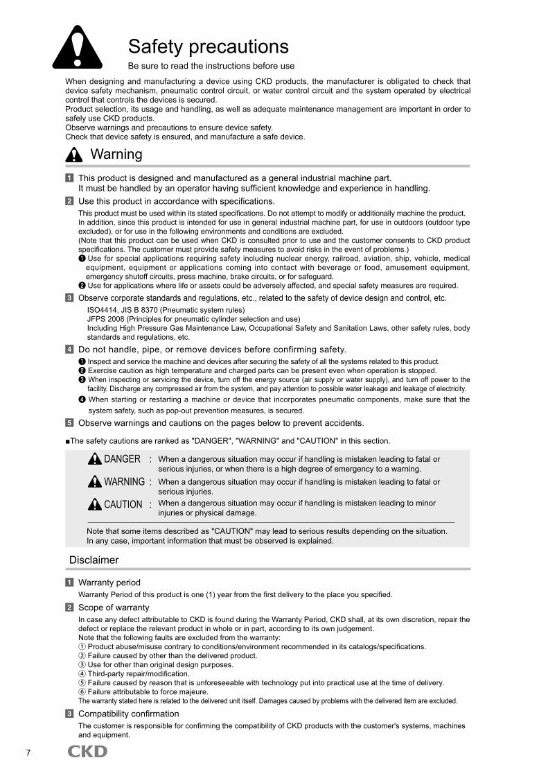
Safety precautionsBe sure to read the instructions before use
When designing and manufacturing a device using CKD products, the manufacturer is obligated to check that device safety mechanism, pneumatic control circuit, or water control circuit and the system operated by electrical control that controls the devices is secured.Product selection, its usage and handling, as well as adequate maintenance management are important in order to safely use CKD products.Observe warnings and precautions to ensure device safety.Check that device safety is ensured, and manufacture a safe device.
1 This product is designed and manufactured as a general industrial machine part.It must be handled by an operator having sufficient knowledge and experience in handling.
2 Use this product in accordance with specifications.This product must be used within its stated specifications. Do not attempt to modify or additionally machine the product.In addition, since this product is intended for use in general industrial machine part, for use in outdoors (outdoor type excluded), or for use in the following environments and conditions are excluded.(Note that this product can be used when CKD is consulted prior to use and the customer consents to CKD product specifications. The customer must provide safety measures to avoid risks in the event of problems.)❶ Use for special applications requiring safety including nuclear energy, railroad, aviation, ship, vehicle, medical
equipment, equipment or applications coming into contact with beverage or food, amusement equipment, emergency shutoff circuits, press machine, brake circuits, or for safeguard.
❷ Use for applications where life or assets could be adversely affected, and special safety measures are required.3 Observe corporate standards and regulations, etc., related to the safety of device design and control, etc.
ISO4414, JIS B 8370 (Pneumatic system rules)JFPS 2008 (Principles for pneumatic cylinder selection and use)Including High Pressure Gas Maintenance Law, Occupational Safety and Sanitation Laws, other safety rules, body standards and regulations, etc.
4 Do not handle, pipe, or remove devices before confirming safety.❶ Inspect and service the machine and devices after securing the safety of all the systems related to this product.❷ Exercise caution as high temperature and charged parts can be present even when operation is stopped.❸ When inspecting or servicing the device, turn off the energy source (air supply or water supply), and turn off power to the
facility. Discharge any compressed air from the system, and pay attention to possible water leakage and leakage of electricity.❹ When starting or restarting a machine or device that incorporates pneumatic components, make sure that the
system safety, such as pop-out prevention measures, is secured.5 Observe warnings and cautions on the pages below to prevent accidents.
Warning
■The safety cautions are ranked as "DANGER", "WARNING" and "CAUTION" in this section.
DANGER : When a dangerous situation may occur if handling is mistaken leading to fatal or serious injuries, or when there is a high degree of emergency to a warning.
WARNING : When a dangerous situation may occur if handling is mistaken leading to fatal or serious injuries.
CAUTION : When a dangerous situation may occur if handling is mistaken leading to minor injuries or physical damage.
Note that some items described as "CAUTION" may lead to serious results depending on the situation.In any case, important information that must be observed is explained.
Disclaimer
1 Warranty periodWarranty Period of this product is one (1) year from the first delivery to the place you specified.
2 Scope of warrantyIn case any defect attributable to CKD is found during the Warranty Period, CKD shall, at its own discretion, repair the defect or replace the relevant product in whole or in part, according to its own judgement.Note that the following faults are excluded from the warranty:① Product abuse/misuse contrary to conditions/environment recommended in its catalogs/specifications.② Failure caused by other than the delivered product.③ Use for other than original design purposes.④ Third-party repair/modification.⑤ Failure caused by reason that is unforeseeable with technology put into practical use at the time of delivery.⑥ Failure attributable to force majeure.The warranty stated here is related to the delivered unit itself. Damages caused by problems with the delivered item are excluded.
3 Compatibility confirmationThe customer is responsible for confirming the compatibility of CKD products with the customer's systems, machines and equipment.
8
Pneumatic components
Safety precautionsBe sure to read the instructions before use.Refer to "Pneumatic, Vacuum and Auxiliary Components CB-024SA".
Design & Selection
Installation & Adjustment
During Use & Maintenance
■Do not exceed the specified range of the product.■ This product is for liquid that does not corrode water
or materials of wetted part over 5μS / cm. Low conductivity liquid cannot be detected properly.
■Please do not use with a plus grounding.■ Please do not use in applications for which it is in direct
contact with beverages, food, and medical fluids.■ Please do not use this product in flammable
gas atmosphere.■ Please maintain fluid temperatures, and for usage in
low temperatures, add such as antifreeze for freeze prevention measures.
■ There is a risk of electric shock on contact with electrical wiring connections.
■ Turn power off before starting wiring. Do not touch the live parts with wet hands.
■Please ensure gas is not mixed in the piping.■ To change the settings, stop the equipment and
change.■ 10 seconds after the power is turned on, since it is
warm-up period, please do not use the display or output during this time.
■ Please do not press setting switch with pointed material.
■ Please do not install in locations exposed to strong light, such as direct sunlight or in a place which receives the radiation from heat sources.
■ While the mounting orientation can be set freely, because it is less susceptible to the effects of bubbles, for lateral piping, it is recommended to mount the display surface horizontal to the ground.
■ Please ensure proper setting of the flow direction of the piping and the flow sensor.
■ Do not drop or hit it, or give excessive shock to it. In addition, please hold the body when handling. (Please do not hold cables)
■ Please maintain the working pressure range during use.
■Please maintain the rated flow range during use.■ If considering lining up several units of this product in
the flow capacity filling type device, please determine the use upon checking Patent No. 3916032.
■ This product cannot be used as a business meter. This product does not conform to Measuring Laws, and thus cannot be used for commercial purposes. Please use this product as an industrial sensor.
■ Please do not install in places where it will be exposed to strong compressive force, tensile force, load, or vibration after installation.
■ Do not step on the product, or place heavy objects on them.
■ Please note that applying excessive load can cause breakage. Please also ensure load from piping is not applied.
■ Please ensure that sealing tape or adhesive do not protrude from the pipe threaded portion.
■ Ensure that the piping just before the sensor is as straight as possible, so that there is no part such as protrusion of the packing that disturbs the flow.
■ Please ensure flow regulating valve is installed downstream of the sensor.
■ Please ensure to attach the sensor after cleaning in case of the presence of foreign matter or oil in the pipe.
■Faulty wiring may cause a malfunction.■ It is recommended that power and receiving
instruments are electrically isolated from each other.■ Do not place excessive tension on the cable.■ Please do not wire with power lines.■ Please keep the product at a distance from power
devices such as high voltage devices and motors, etc.
CAUTION
■ The product may be damaged by pressure rise due to temperature change in the liquid sealed circuit.
Provide a relief valve so that a liquid ring circuit is not created.
■ If no fluid is flowing, make sure to turn the power OFF. Keeping the power on while no fluid is flowing may cause a malfunction.
■ Do not disassemble this product. The specifications are not satisfied if a disassembled product is reassembled.
WFC Series
2015.10
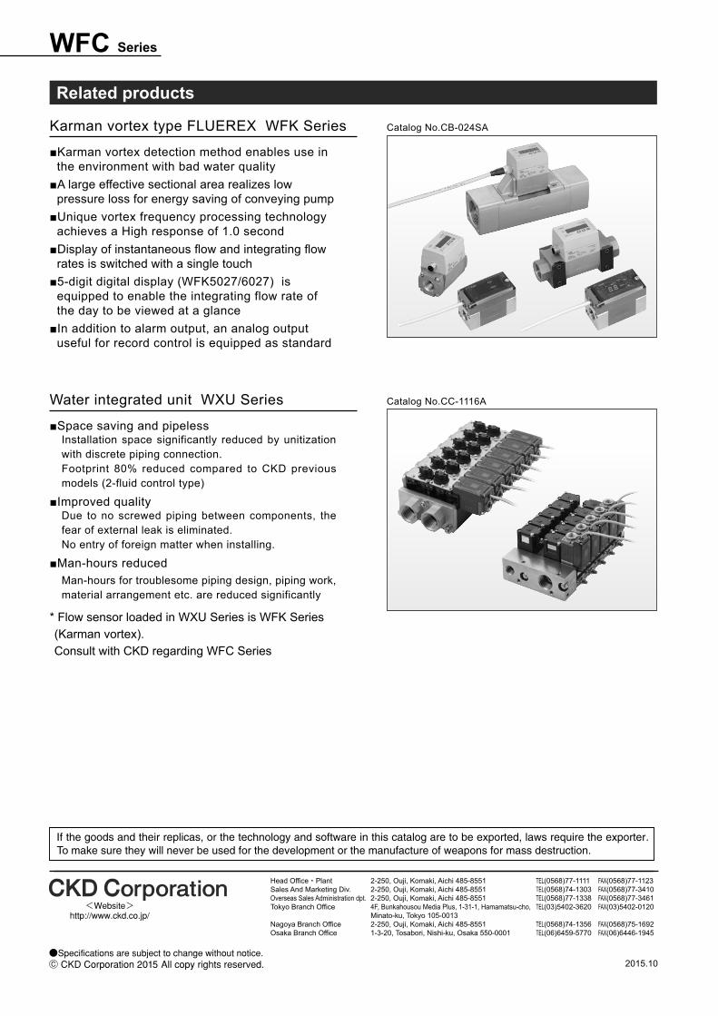
Related products
Catalog No.CB-024SA
Catalog No.CC-1116A
■ Karman vortex detection method enables use in the environment with bad water quality
■ A large effective sectional area realizes low pressure loss for energy saving of conveying pump
■ Unique vortex frequency processing technology achieves a High response of 1.0 second
■ Display of instantaneous flow and integrating flow rates is switched with a single touch
■ 5-digit digital display (WFK5027/6027) is equipped to enable the integrating flow rate of the day to be viewed at a glance
■ In addition to alarm output, an analog output useful for record control is equipped as standard
■Space saving and pipelessInstallation space significantly reduced by unitization with discrete piping connection.Footprint 80% reduced compared to CKD previous models (2-fluid control type)
■Improved qualityDue to no screwed piping between components, the fear of external leak is eliminated.No entry of foreign matter when installing.
■Man-hours reducedMan-hours for troublesome piping design, piping work, material arrangement etc. are reduced significantly
Karman vortex type FLUEREX WFK Series
Water integrated unit WXU Series
* Flow sensor loaded in WXU Series is WFK Series (Karman vortex). Consult with CKD regarding WFC Series