Reducing Power Consumption with Relaxed Quasi Delay-Insensitive Circuits
3rd ANSA & μETA International Conference September 9-11, 2009 Olympic Convention Centre, Porto Carras Grand Resort Hotel, Halkidiki Greece
MINIMIZING FUEL CONSUMPTION WITH CFD AND AUTOMATED MORPHING 1Simon Michalowski, 1Andrea Pieck, 1Morten Goedecke, 2Michael Teller 1Wilhelm Karmann GmbH, Germany, 2University of Applied Sciences Trier, Germany KEYWORDS – aerodynamics, optimization, morphing, LS-OPT, POWERFLOW ABSTRACT – Minimization of fuel consumption becomes more and more important against the background of limited energy resources. Modern CAE methods provide high capabilities for optimized designs and fast design processes. The practical use of these processes is shown by an example of an efficient car for the Shell Eco-marathon. The Shell Eco-marathon, which has been started in 2009 for the 25th time, challenges students around the world to design, build and test vehicles that travel further using less energy. The proTRon Team of the UAS Trier is a successful participant in the prototype class for the last two years. In 2009 the students started for the first time in the UrbanConcept Group, which has special rules and regulations to realize more realistic cars. The Wilhelm Karmann GmbH supported the team in the styling process and in some aerodynamic optimization issues. This work demonstrates the product development, which needed to be realized in a very short time, i.e. starting in October 2008 until the race in may 2009. As an example for a modern development process and the use of computational methods, the shape of the car's nose has been designed to realize the best aerodynamic performance. Therefore an automated CAE process was built. Here the optimization software LS-OPT controls the morphing in ANSA with a batch mode script and the CFD solver POWERFLOW as well as a post-processing script to capture the drag coefficient CD. With this process, a drag coefficient for a two-seated car could of CD = 0.18 could be realized. TECHNICAL PAPER - 1. INTRODUCTION The Shell Eco-marathon, which has been started in 2009 for the 25th time, challenges students around the world to design, build and test vehicles that travel further using less energy. The proTRon Team of the UAS Trier is a successful participant in the prototype class for the last two years. In 2009 the students started for the first time in the UrbanConcept Group, which has special rules and regulations to realize more realistic cars (1). According the body, the regulations allow only cars with four wheels and minimum dimensions, which ensure practical usability. The vehicles may use different fuel or energy types:
• Petrol/Gasoline • Diesel • Liquefied Petroleum Gas (LPG) • Gas To Liquid (100% GTL) • Fatty Acid Methyl Ester (100% FAME) • Ethanol E100 (100% Ethanol) • Hydrogen • Solar
As the UAS Trier has participated successfully in the prototype class since 2007, it was obvious to carry over the complete hydrogen fuel cell drive train and integrate this into the UrbanConcept car. However, a complete new body and chassis was required for this car. The students of the UAS Trier have experience in the handcraft building of a body in carbon
3rd ANSA & μETA International Conference September 9-11, 2009 Olympic Convention Centre, Porto Carras Grand Resort Hotel, Halkidiki Greece
fiber and in designing the chassis. The only issue, they requested support from an external facility was the styling and the aerodynamic optimization. 2. THE STYLING PROCESS Between the decision of the UAS Trier to start in the UrbanConcept Group and the race, was a timeline of seven months (from October to 9th of May). In November the project started with an initial workshop with the aim to determine the project targets as well as a time schedule. Besides fulfilling the criterion of the official rule, the following targets had to be fulfilled:
• Attributes: futuristic, sporty • Performance: Aerodynamics, Weight • Feasibility: Simple shapes, easy to build with vacuum infusion process (chapter 5) • Suitability for daily use: Two seats, ergonomics, trunk compartment • With lower priority it is intended to get official approval and homologation for later
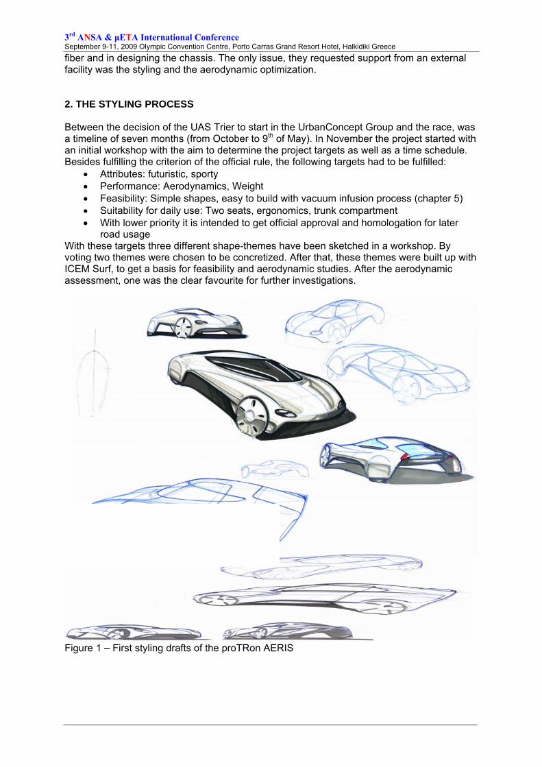
road usage With these targets three different shape-themes have been sketched in a workshop. By voting two themes were chosen to be concretized. After that, these themes were built up with ICEM Surf, to get a basis for feasibility and aerodynamic studies. After the aerodynamic assessment, one was the clear favourite for further investigations.
Figure 1 – First styling drafts of the proTRon AERIS
3rd ANSA & μETA International Conference September 9-11, 2009 Olympic Convention Centre, Porto Carras Grand Resort Hotel, Halkidiki Greece
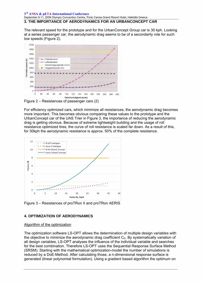
3. THE IMPORTANCE OF AERODYNAMICS FOR AN URBANCONCEPT CAR The relevant speed for the prototype and for the UrbanConcept Group car is 30 kph. Looking at a series passenger car, the aerodynamic drag seems to be of a secondarily role for such low speeds (Figure 2).
Figure 2 – Resistances of passenger cars (2) For efficiency optimized cars, which minimize all resistances, the aerodynamic drag becomes more important. This becomes obvious comparing these values to the prototype and the UrbanConcept car of the UAS Trier in Figure 3, the importance of reducing the aerodynamic drag is getting obvious. Because of extreme lightweight building and the usage of roll resistance optimized tires, the curve of roll resistance is scaled far down. As a result of this, for 30kph the aerodynamic resistance is approx. 50% of the complete resistance.
0
2
4
6
8
10
12
0 5 10 15 20 25 30 35 40
Veloc ity / kph
Force / N
F ‐R oll P rototypeF ‐Aero P rototypeF ‐R oll UrbanC onceptF ‐Aero UrbanC oncept
Figure 3 – Resistances of proTRon II and proTRon AERIS 4. OPTIMIZATION OF AERODYNAMICS Algorithm of the optimization The optimization software LS-OPT allows the determination of multiple design variables with the objective to minimize the aerodynamic drag coefficient CD. By systematically variation of all design variables, LS-OPT analyses the influence of the individual variable and searches for the best combination. Therefore LS-OPT uses the Sequential Response Surface Method (SRSM). Starting with the mathematical optimization-model the number of simulations is reduced by a DoE-Method. After calculating those, a n-dimensional response surface is generated (linear polynomial formulation). Using a gradient based algorithm the optimum on
3rd ANSA & μETA International Conference September 9-11, 2009 Olympic Convention Centre, Porto Carras Grand Resort Hotel, Halkidiki Greece
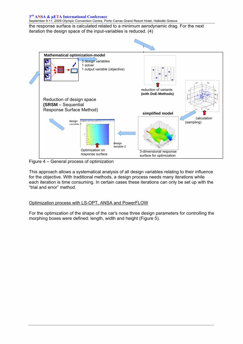
the response surface is calculated related to a minimum aerodynamic drag. For the next iteration the design space of the input-variables is reduced. (4)
Figure 4 – General process of optimization This approach allows a systematical analysis of all design variables relating to their influence for the objective. With traditional methods, a design process needs many iterations while each iteration is time consuming. In certain cases these iterations can only be set up with the “trial and error” method. Optimization process with LS-OPT, ANSA and PowerFLOW For the optimization of the shape of the car's nose three design parameters for controlling the morphing boxes were defined: length, width and height (Figure 5).
Mathematical optimization-model 3 design variables 1 solver 1 output variable (objective)
calculation (sampling)
T 1
Optimization on response surface
3-dimensional response surface for optimization
simplified model
design variable 1
design variable 2
reduction of variants (with DoE-Methods)
Reduction of design space (SRSM – Sequential Response Surface Method)
3rd ANSA & μETA International Conference September 9-11, 2009 Olympic Convention Centre, Porto Carras Grand Resort Hotel, Halkidiki Greece
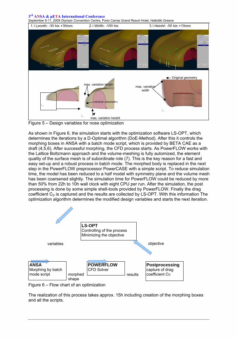
Figure 5 – Design variables for nose optimization As shown in Figure 6, the simulation starts with the optimization software LS-OPT, which determines the iterations by a D-Optimal algorithm (DoE-Method). After this it controls the morphing boxes in ANSA with a batch mode script, which is provided by BETA CAE as a draft (4,5,6). After successful morphing, the CFD process starts. As PowerFLOW works with the Lattice Boltzmann approach and the volume-meshing is fully automized, the element quality of the surface mesh is of subordinate role (7). This is the key reason for a fast and easy set-up and a robust process in batch mode. The morphed body is replaced in the next step in the PowerFLOW preprocessor PowerCASE with a simple script. To reduce simulation time, the model has been reduced to a half model with symmetry plane and the volume mesh has been coarsened slightly. The simulation time for PowerFLOW could be reduced by more than 50% from 22h to 10h wall clock with eight CPU per run. After the simulation, the post processing is done by some simple shell-tools provided by PowerFLOW. Finally the drag coefficient CD is captured and the results are collected by LS-OPT. With this information The optimization algorithm determines the modified design variables and starts the next iteration.
Figure 6 – Flow chart of an optimization The realization of this process takes approx. 15h including creation of the morphing boxes and all the scripts.
1.) Length: -30 bis +30mm 2.) Width: -100 bis 3.) Height: -50 bis +10mm
original geometry
max. variation height
max. variation length
Original geometry
max. variation width
LS-OPT Controlling of the process Minimizing the objective
ANSA Morphing by batch mode script
POWERFLOW CFD Solver
Postprocessing capture of drag coefficient CD
variables
morphed shape
results
objective
3rd ANSA & μETA International Conference September 9-11, 2009 Olympic Convention Centre, Porto Carras Grand Resort Hotel, Halkidiki Greece
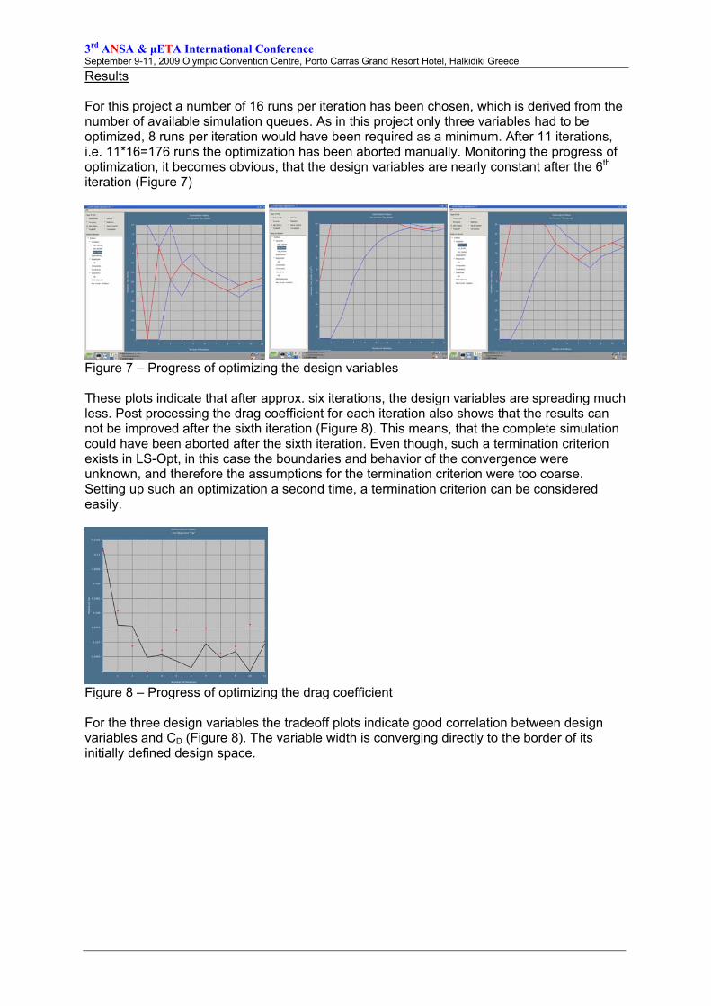
Results For this project a number of 16 runs per iteration has been chosen, which is derived from the number of available simulation queues. As in this project only three variables had to be optimized, 8 runs per iteration would have been required as a minimum. After 11 iterations, i.e. 11*16=176 runs the optimization has been aborted manually. Monitoring the progress of optimization, it becomes obvious, that the design variables are nearly constant after the 6th iteration (Figure 7)
Figure 7 – Progress of optimizing the design variables These plots indicate that after approx. six iterations, the design variables are spreading much less. Post processing the drag coefficient for each iteration also shows that the results can not be improved after the sixth iteration (Figure 8). This means, that the complete simulation could have been aborted after the sixth iteration. Even though, such a termination criterion exists in LS-Opt, in this case the boundaries and behavior of the convergence were unknown, and therefore the assumptions for the termination criterion were too coarse. Setting up such an optimization a second time, a termination criterion can be considered easily.
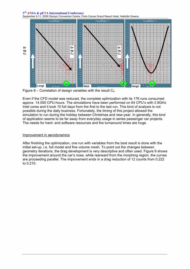
Figure 8 – Progress of optimizing the drag coefficient For the three design variables the tradeoff plots indicate good correlation between design variables and CD (Figure 8). The variable width is converging directly to the border of its initially defined design space.
3rd ANSA & μETA International Conference September 9-11, 2009 Olympic Convention Centre, Porto Carras Grand Resort Hotel, Halkidiki Greece
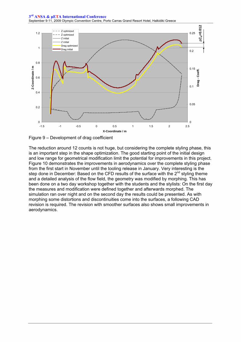
Figure 8 – Correlation of design variables with the result CD Even if the CFD model was reduced, the complete optimization with its 176 runs consumed approx. 14.000 CPU-hours. The simulations have been performed on 64 CPU’s with 2.8GHz Intel cores and it took 10 full days from the first to the last run. This kind of analysis is not possible during the daily business. Fortunately, the timing of this project allowed the simulation to run during the holiday between Christmas and new-year. In generally, this kind of application seems to be far away from everyday usage in series passenger car projects. The needs for hard- and software resources and the turnaround times are huge. Improvement in aerodynamics After finishing the optimization, one run with variables from the best result is done with the initial set-up, i.e. full model and fine volume mesh. To point out the changes between geometry iterations, the drag development is very descriptive and often used. Figure 9 shows the improvement around the car’s nose, while rearward from the morphing region, the curves are proceeding parallel. The improvement ends in a drag reduction of 12 counts from 0.222 to 0.210.
Drag CD
Drag CD
DragCD
Lengt Widt Heigh
3rd ANSA & μETA International Conference September 9-11, 2009 Olympic Convention Centre, Porto Carras Grand Resort Hotel, Halkidiki Greece
0
0.2
0.4
0.6
0.8
1
1.2
-1.5 -1 -0.5 0 0.5 1 1.5 2 2.5
X-Coordinate / m
Z-C
oord
inat
e / m
0
0.05
0.1
0.15
0.2
0.25
Dra
g - C
oeff.
Z optimizedZ optimizedZ initialZ initialDrag optimizedDrag initial
ΔC
d=0.
012
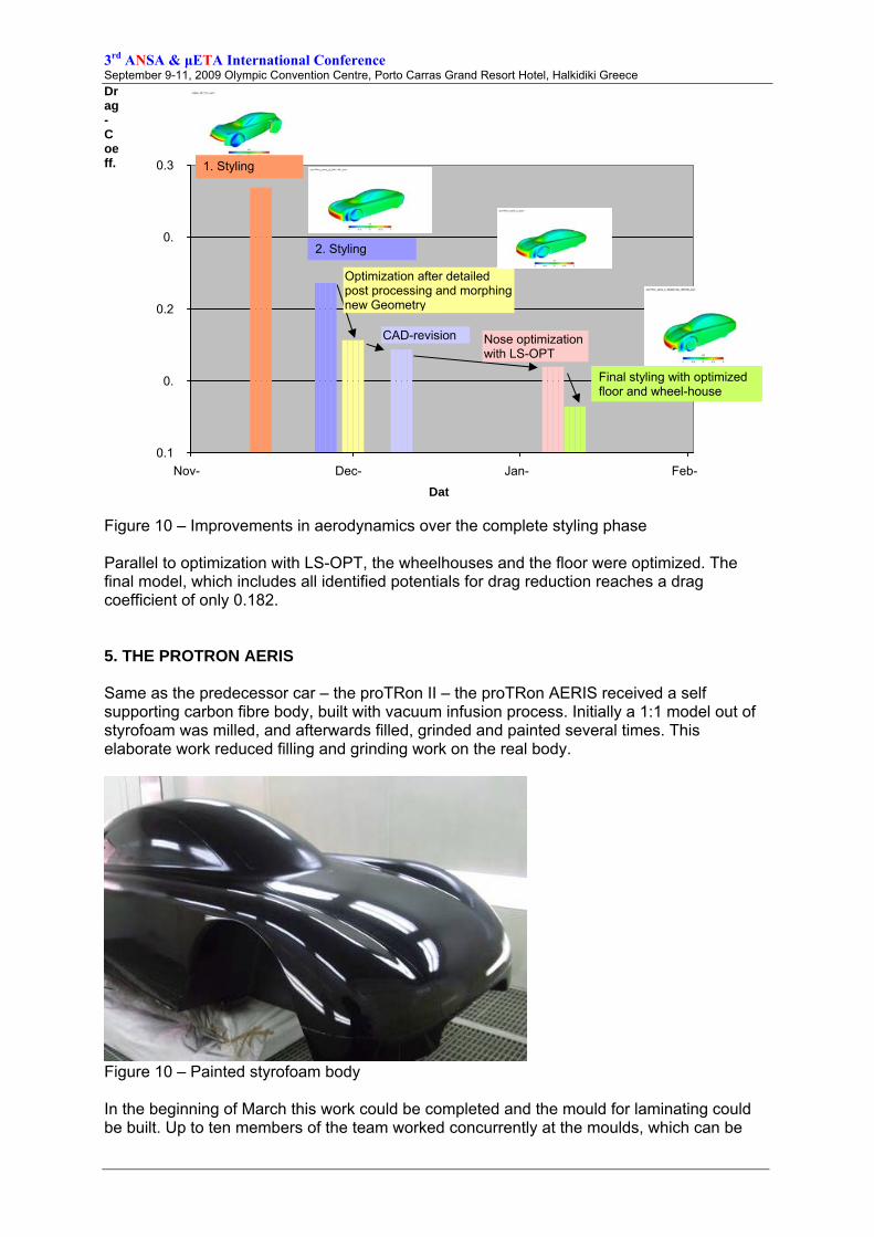
Figure 9 – Development of drag coefficient The reduction around 12 counts is not huge, but considering the complete styling phase, this is an important step in the shape optimization. The good starting point of the initial design and low range for geometrical modification limit the potential for improvements in this project. Figure 10 demonstrates the improvements in aerodynamics over the complete styling phase from the first start in November until the tooling release in January. Very interesting is the step done in December: Based on the CFD results of the surface with the 2nd styling theme and a detailed analysis of the flow field, the geometry was modified by morphing. This has been done on a two day workshop together with the students and the stylists: On the first day the measures and modification were defined together and afterwards morphed. The simulation ran over night and on the second day the results could be presented. As with morphing some distortions and discontinuities come into the surfaces, a following CAD revision is required. The revision with smoother surfaces also shows small improvements in aerodynamics.
3rd ANSA & μETA International Conference September 9-11, 2009 Olympic Convention Centre, Porto Carras Grand Resort Hotel, Halkidiki Greece
Figure 10 – Improvements in aerodynamics over the complete styling phase Parallel to optimization with LS-OPT, the wheelhouses and the floor were optimized. The final model, which includes all identified potentials for drag reduction reaches a drag coefficient of only 0.182. 5. THE PROTRON AERIS Same as the predecessor car – the proTRon II – the proTRon AERIS received a self supporting carbon fibre body, built with vacuum infusion process. Initially a 1:1 model out of styrofoam was milled, and afterwards filled, grinded and painted several times. This elaborate work reduced filling and grinding work on the real body.
Figure 10 – Painted styrofoam body In the beginning of March this work could be completed and the mould for laminating could be built. Up to ten members of the team worked concurrently at the moulds, which can be
0.1
0.
0.2
0.
0.3
Nov- Dec- Jan- Feb-
Dat
Drag-Coeff. 1. Styling
2. Styling
Optimization after detailed post processing and morphing new Geometry
CAD-revision Nose optimization with LS-OPT
Final styling with optimized floor and wheel-house
3rd ANSA & μETA International Conference September 9-11, 2009 Olympic Convention Centre, Porto Carras Grand Resort Hotel, Halkidiki Greece
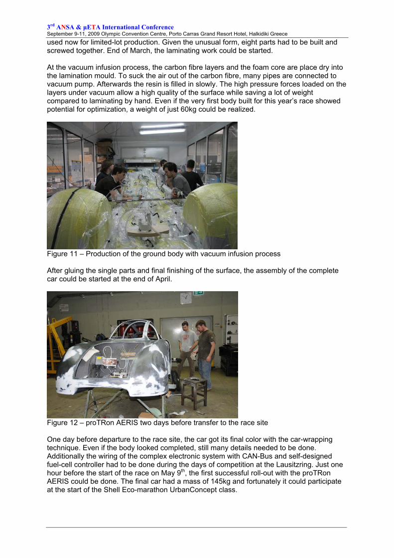
used now for limited-lot production. Given the unusual form, eight parts had to be built and screwed together. End of March, the laminating work could be started. At the vacuum infusion process, the carbon fibre layers and the foam core are place dry into the lamination mould. To suck the air out of the carbon fibre, many pipes are connected to vacuum pump. Afterwards the resin is filled in slowly. The high pressure forces loaded on the layers under vacuum allow a high quality of the surface while saving a lot of weight compared to laminating by hand. Even if the very first body built for this year’s race showed potential for optimization, a weight of just 60kg could be realized.
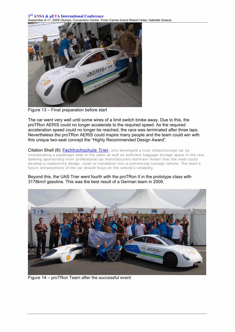
Figure 11 – Production of the ground body with vacuum infusion process After gluing the single parts and final finishing of the surface, the assembly of the complete car could be started at the end of April.
Figure 12 – proTRon AERIS two days before transfer to the race site One day before departure to the race site, the car got its final color with the car-wrapping technique. Even if the body looked completed, still many details needed to be done. Additionally the wiring of the complex electronic system with CAN-Bus and self-designed fuel-cell controller had to be done during the days of competition at the Lausitzring. Just one hour before the start of the race on May 9th, the first successful roll-out with the proTRon AERIS could be done. The final car had a mass of 145kg and fortunately it could participate at the start of the Shell Eco-marathon UrbanConcept class.
3rd ANSA & μETA International Conference September 9-11, 2009 Olympic Convention Centre, Porto Carras Grand Resort Hotel, Halkidiki Greece
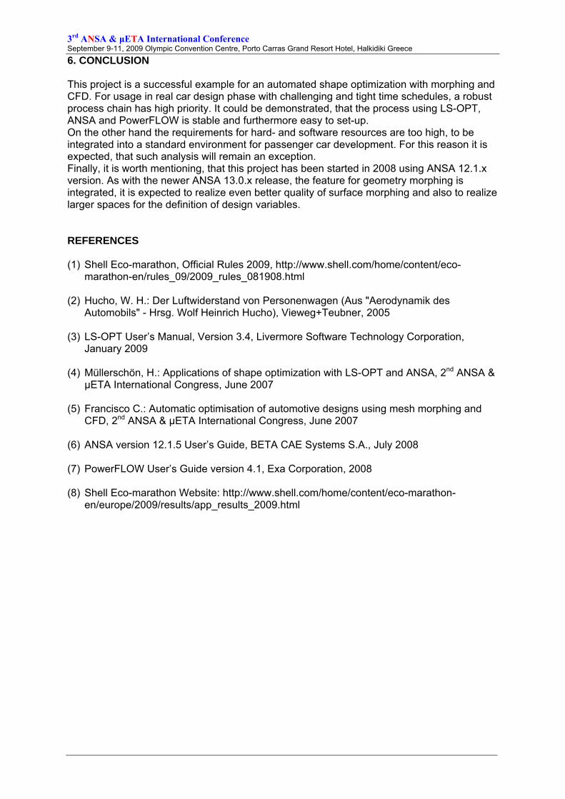
Figure 13 – Final preparation before start The car went very well until some wires of a limit switch broke away. Due to this, the proTRon AERIS could no longer accelerate to the required speed. As the required acceleration speed could no longer be reached, the race was terminated after three laps. Nevertheless the proTRon AERIS could inspire many people and the team could win with this unique two-seat concept the “Highly Recommended Design Award”. Citation Shell (8): Fachhochschule Trier, who developed a truly UrbanConcept car by incorporating a passenger seat in the cabin as well as sufficient baggage storage space in the rear. Seeking sponsorship from professional car manufacturers Karmann meant that the team could develop a roadworthy design, close to translation into a commercial concept vehicle. The team’s future enhancement of the car should focus on the vehicle’s reliability. Beyond this, the UAS Trier went fourth with the proTRon II in the prototype class with 3178km/l gasoline. This was the best result of a German team in 2009.
Figure 14 – proTRon Team after the successful event
3rd ANSA & μETA International Conference September 9-11, 2009 Olympic Convention Centre, Porto Carras Grand Resort Hotel, Halkidiki Greece
6. CONCLUSION This project is a successful example for an automated shape optimization with morphing and CFD. For usage in real car design phase with challenging and tight time schedules, a robust process chain has high priority. It could be demonstrated, that the process using LS-OPT, ANSA and PowerFLOW is stable and furthermore easy to set-up. On the other hand the requirements for hard- and software resources are too high, to be integrated into a standard environment for passenger car development. For this reason it is expected, that such analysis will remain an exception. Finally, it is worth mentioning, that this project has been started in 2008 using ANSA 12.1.x version. As with the newer ANSA 13.0.x release, the feature for geometry morphing is integrated, it is expected to realize even better quality of surface morphing and also to realize larger spaces for the definition of design variables. REFERENCES (1) Shell Eco-marathon, Official Rules 2009, http://www.shell.com/home/content/eco-
marathon-en/rules_09/2009_rules_081908.html (2) Hucho, W. H.: Der Luftwiderstand von Personenwagen (Aus "Aerodynamik des
Automobils" - Hrsg. Wolf Heinrich Hucho), Vieweg+Teubner, 2005 (3) LS-OPT User’s Manual, Version 3.4, Livermore Software Technology Corporation,
January 2009 (4) Müllerschön, H.: Applications of shape optimization with LS-OPT and ANSA, 2nd ANSA &
μETA International Congress, June 2007 (5) Francisco C.: Automatic optimisation of automotive designs using mesh morphing and
CFD, 2nd ANSA & μETA International Congress, June 2007 (6) ANSA version 12.1.5 User’s Guide, BETA CAE Systems S.A., July 2008 (7) PowerFLOW User’s Guide version 4.1, Exa Corporation, 2008 (8) Shell Eco-marathon Website: http://www.shell.com/home/content/eco-marathon-
en/europe/2009/results/app_results_2009.html