LEC8 FREQUENCY RESPONSE (OF CIRCUITS AND FILTERS)
50
LEC 8 FREQUENCY RESPONSE (OF CIRCUITS AND FILTERS) Analogue Electronics and Systems
Transcript of LEC8 FREQUENCY RESPONSE (OF CIRCUITS AND FILTERS)
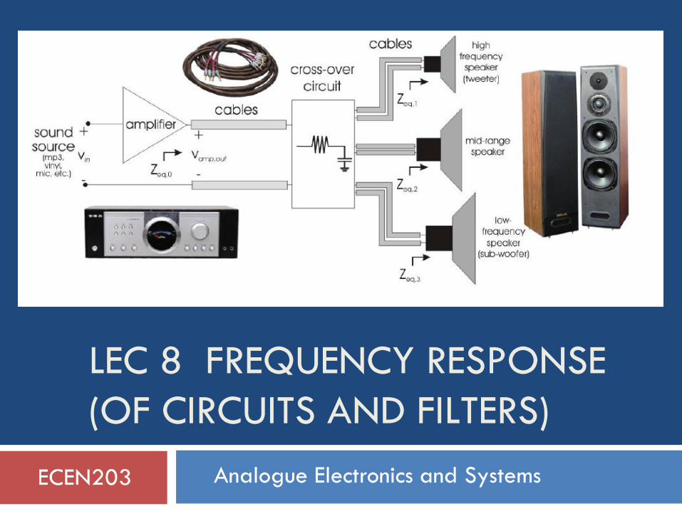
LEC 8 FREQUENCY RESPONSE
(OF CIRCUITS AND FILTERS)
Analogue Electronics and Systems
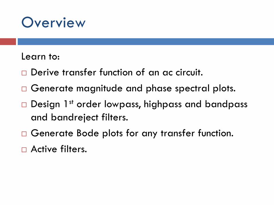
Overview
Learn to:
Derive transfer function of an ac circuit.
Generate magnitude and phase spectral plots.
Design 1st order lowpass, highpass and bandpass
and bandreject filters.
Generate Bode plots for any transfer function.
Active filters.
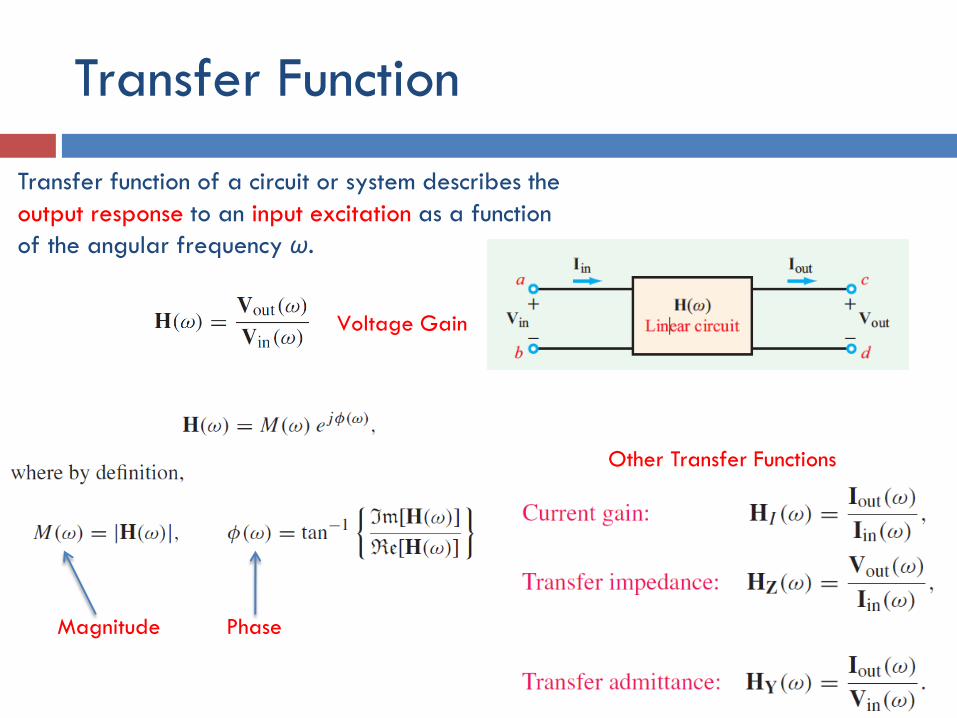
Transfer Function
Transfer function of a circuit or system describes the
output response to an input excitation as a function
of the angular frequency ω.
Voltage Gain
Other Transfer Functions
Magnitude Phase
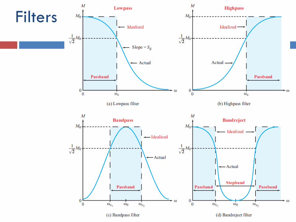
Filters
Filter terminology
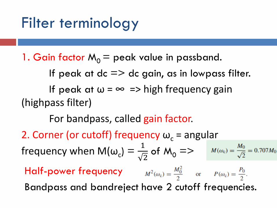
1. Gain factor M0 = peak value in passband.
If peak at dc => dc gain, as in lowpass filter.
If peak at ω = ∞ => high frequency gain (highpass filter)
For bandpass, called gain factor.
2. Corner (or cutoff) frequency ωc = angular
frequency when M(ωc) = 1
2of M0 =>
Half-power frequency
Bandpass and bandreject have 2 cutoff frequencies.
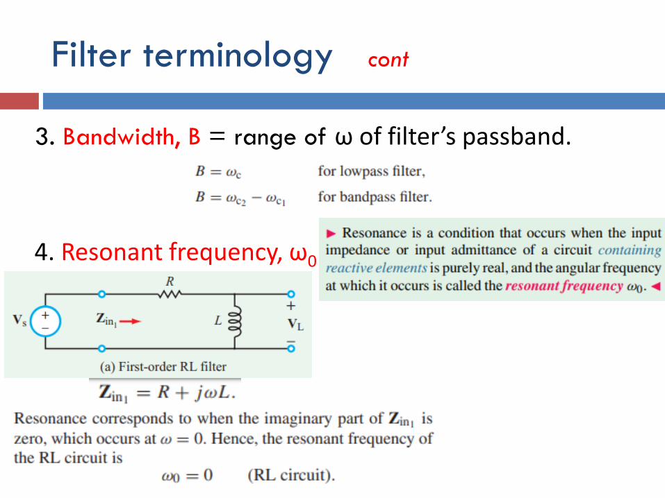
Filter terminology cont
3. Bandwidth, B = range of ω of filter’s passband.
4. Resonant frequency, ω0
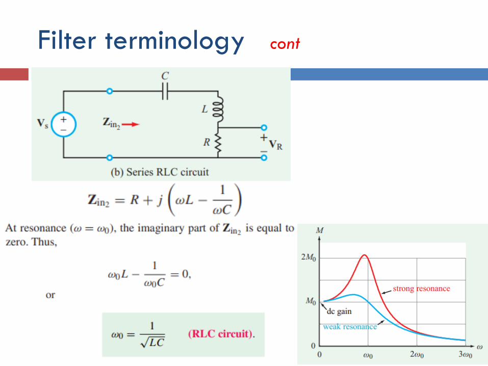
Filter terminology cont
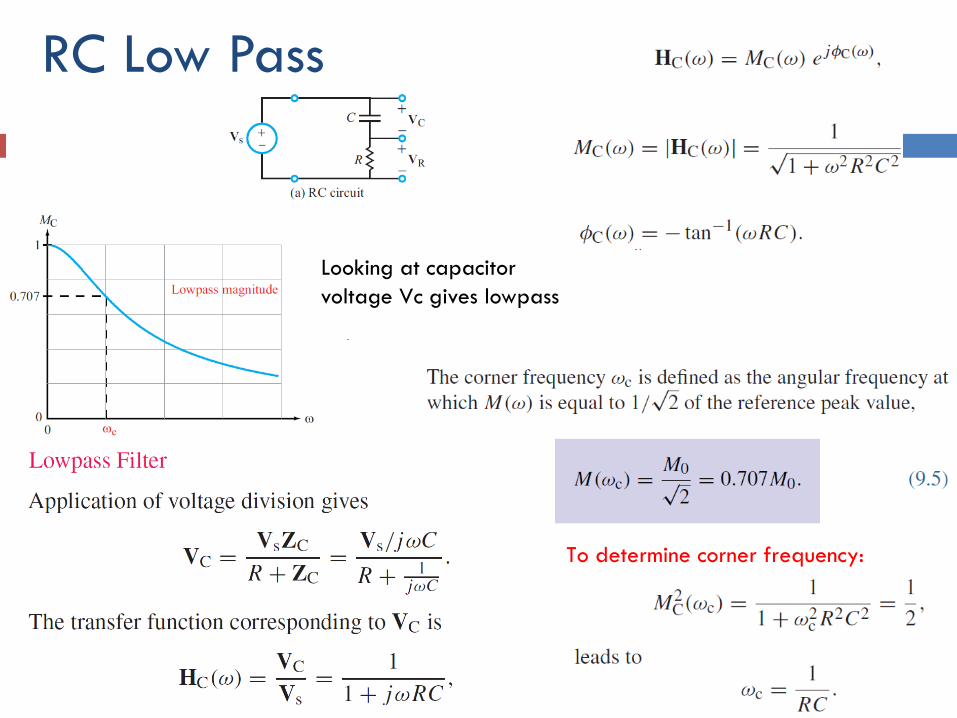
RC Low Pass
To determine corner frequency:
Looking at capacitor
voltage Vc gives lowpass
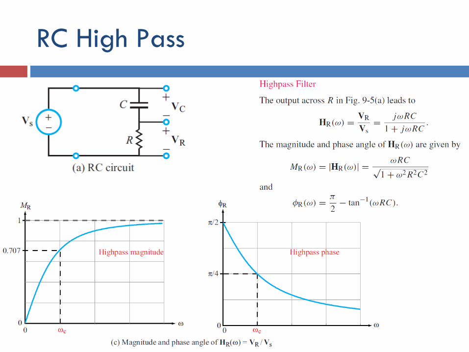
RC High Pass
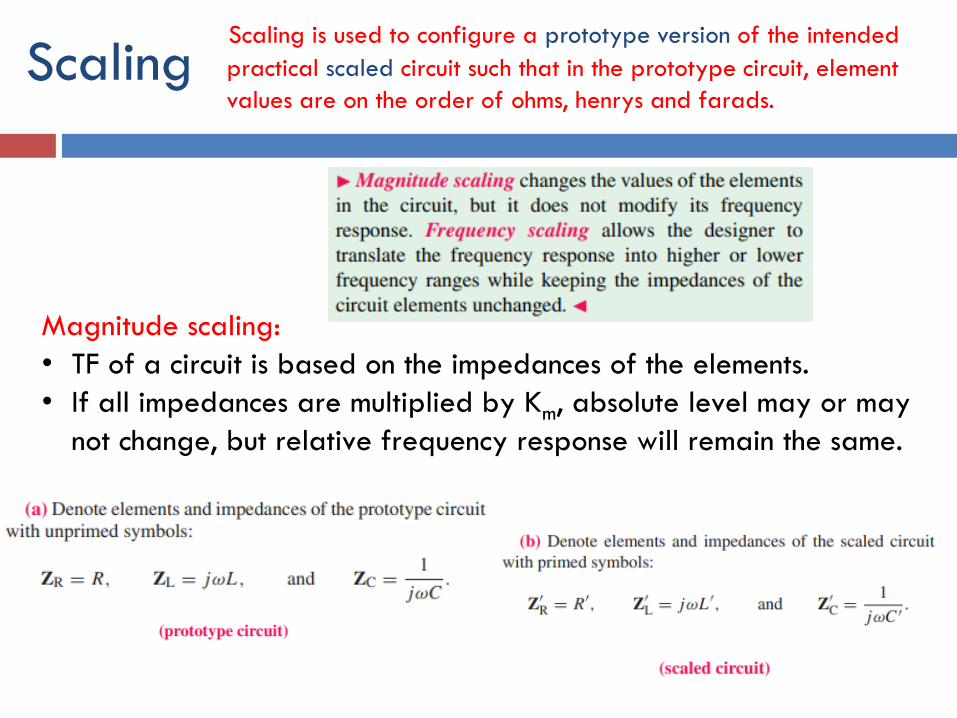
ScalingScaling is used to configure a prototype version of the intended
practical scaled circuit such that in the prototype circuit, element
values are on the order of ohms, henrys and farads.
Magnitude scaling:
• TF of a circuit is based on the impedances of the elements.
• If all impedances are multiplied by Km, absolute level may or may
not change, but relative frequency response will remain the same.
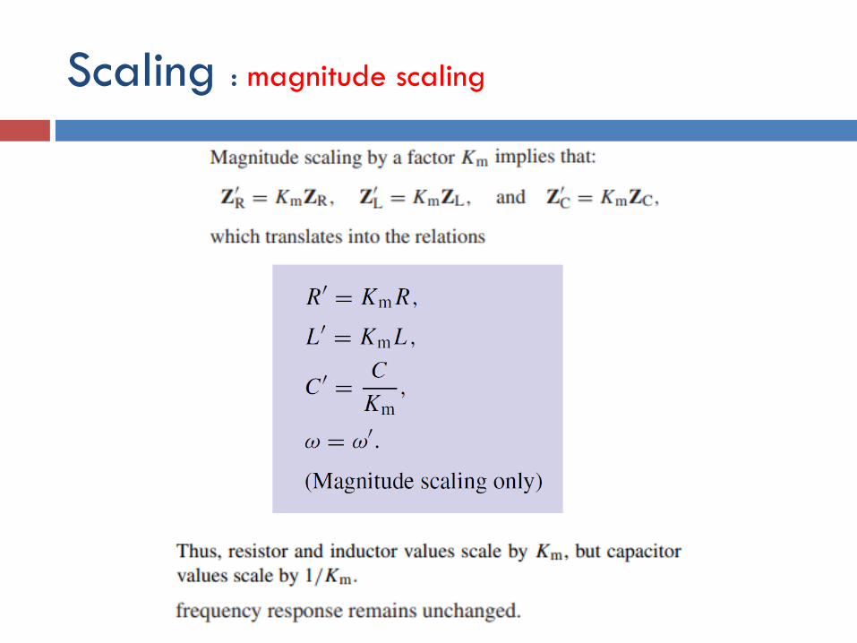
Scaling : magnitude scaling
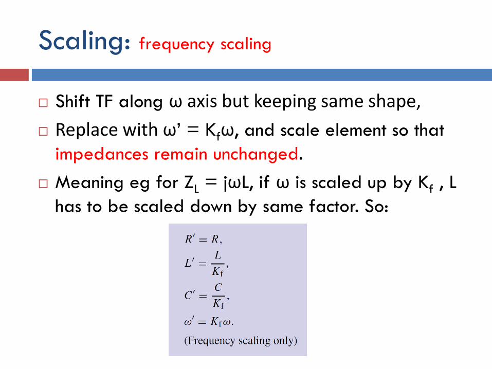
Scaling: frequency scaling
Shift TF along ω axis but keeping same shape,
Replace with ω’ = Kfω, and scale element so that
impedances remain unchanged.
Meaning eg for ZL = jωL, if ω is scaled up by Kf , L
has to be scaled down by same factor. So:
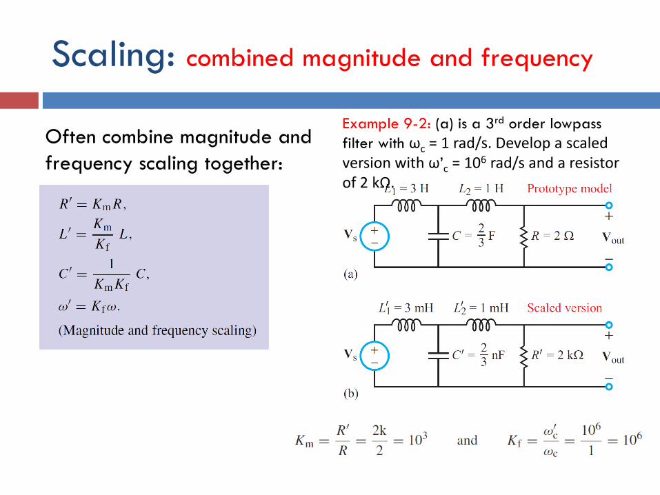
Scaling: combined magnitude and frequency
Often combine magnitude and
frequency scaling together:
Example 9-2: (a) is a 3rd order lowpass
filter with ωc = 1 rad/s. Develop a scaled version with ω’c = 106 rad/s and a resistor of 2 kΩ.
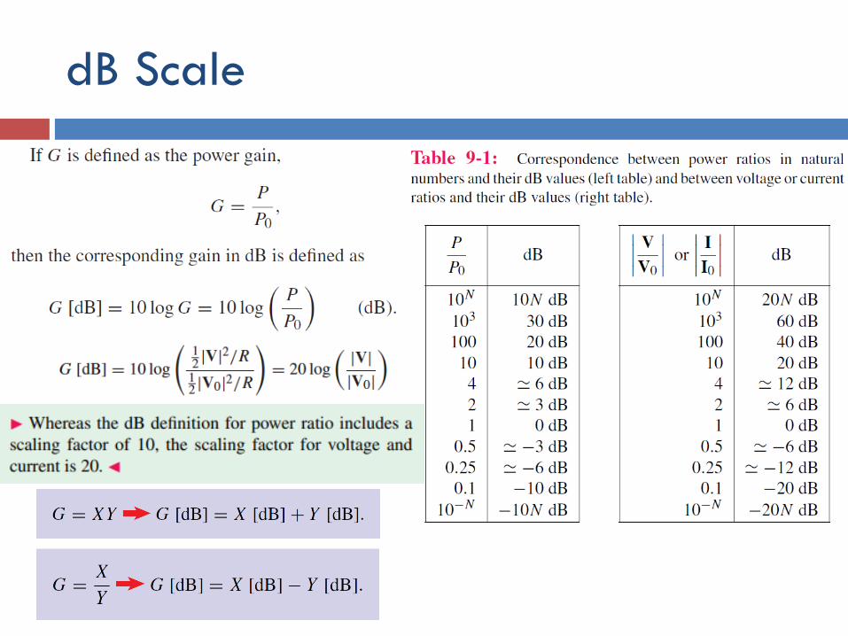
dB Scale
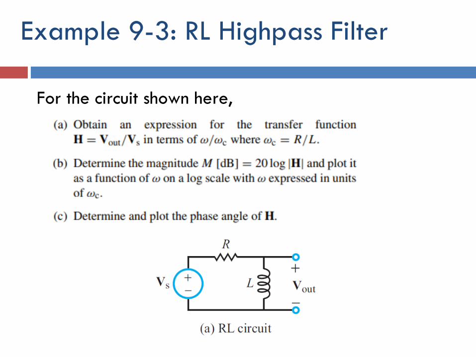
For the circuit shown here,
Example 9-3: RL Highpass Filter
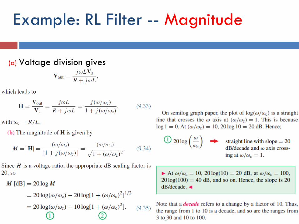
Example: RL Filter -- Magnitude
(a) Voltage division gives
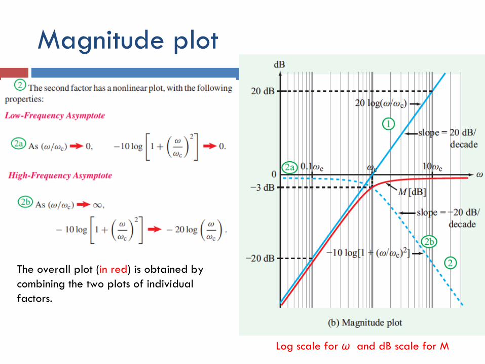
Magnitude plot
Log scale for ω and dB scale for M
The overall plot (in red) is obtained by
combining the two plots of individual
factors.
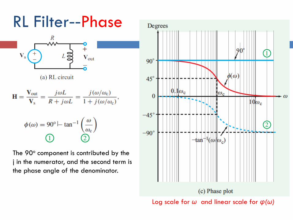
RL Filter--Phase
Log scale for ω and linear scale for φ(ω)
The 90o component is contributed by the
j in the numerator, and the second term is
the phase angle of the denominator.
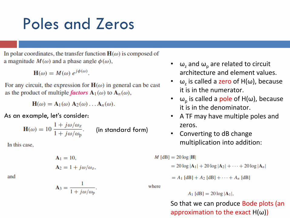
Poles and Zeros
As an example, let’s consider:
(in standard form)
• ωz and ωp are related to circuit architecture and element values.
• ωz is called a zero of H(ω), because it is in the numerator.
• ωp is called a pole of H(ω), because it is in the denominator.
• A TF may have multiple poles and zeros.
• Converting to dB change multiplication into addition:
So that we can produce Bode plots (an approximation to the exact H(ω))
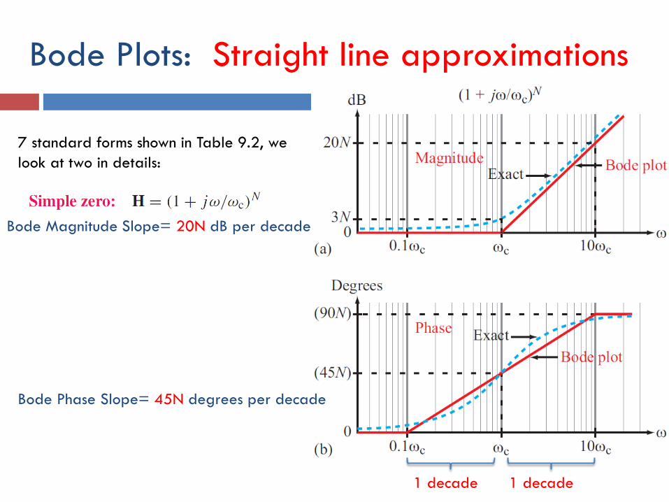
Bode Plots: Straight line approximations
Bode Magnitude Slope= 20N dB per decade
Bode Phase Slope= 45N degrees per decade
1 decade 1 decade
7 standard forms shown in Table 9.2, we
look at two in details:
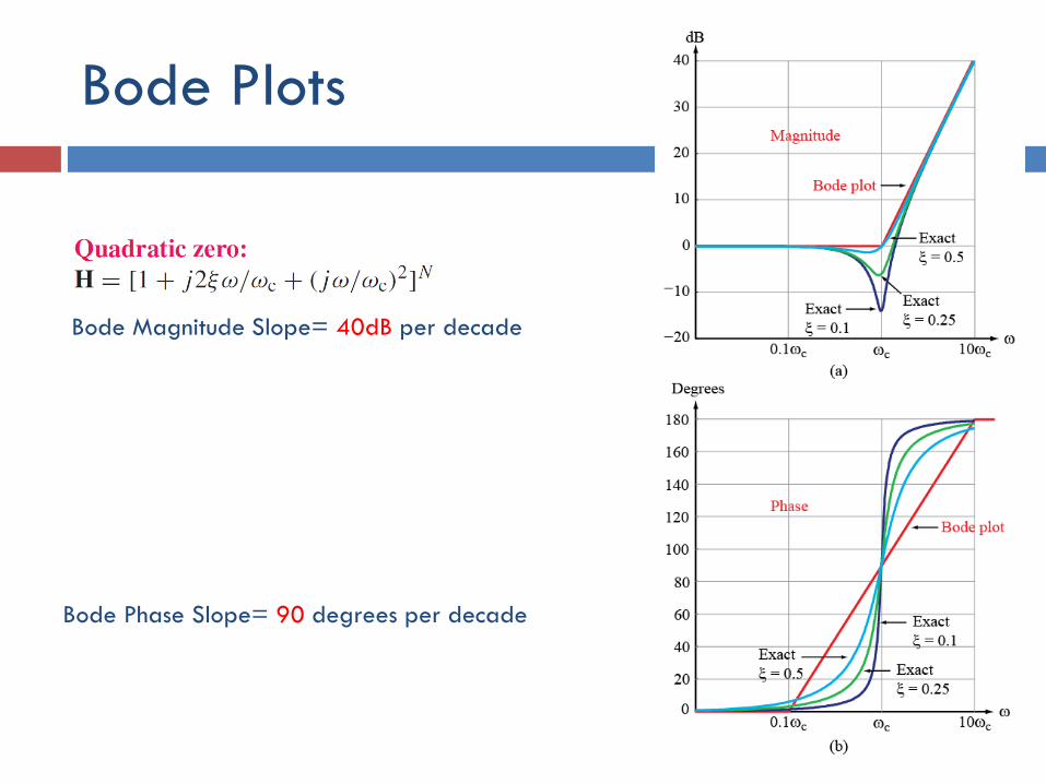
Bode Plots
Bode Magnitude Slope= 40dB per decade
Bode Phase Slope= 90 degrees per decade
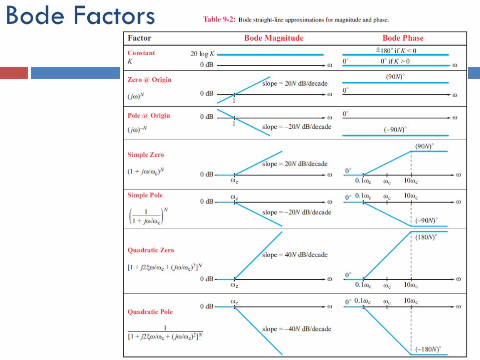
Bode Factors
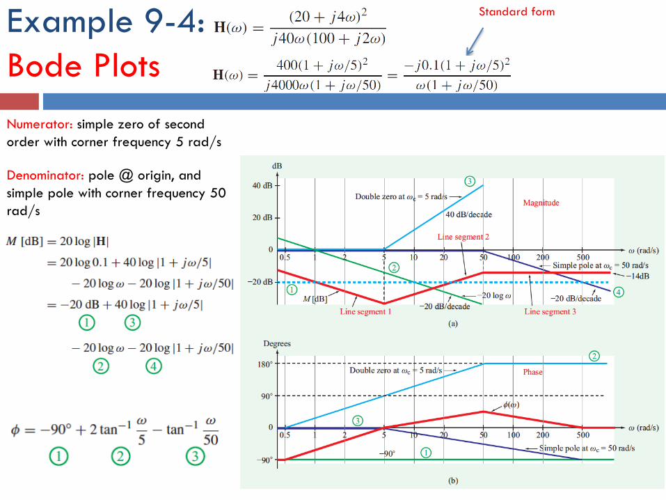
Example 9-4:
Bode Plots
Standard form
Numerator: simple zero of second
order with corner frequency 5 rad/s
Denominator: pole @ origin, and
simple pole with corner frequency 50
rad/s
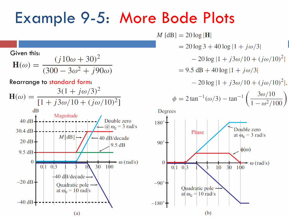
Example 9-5: More Bode Plots
Given this:
Rearrange to standard form:
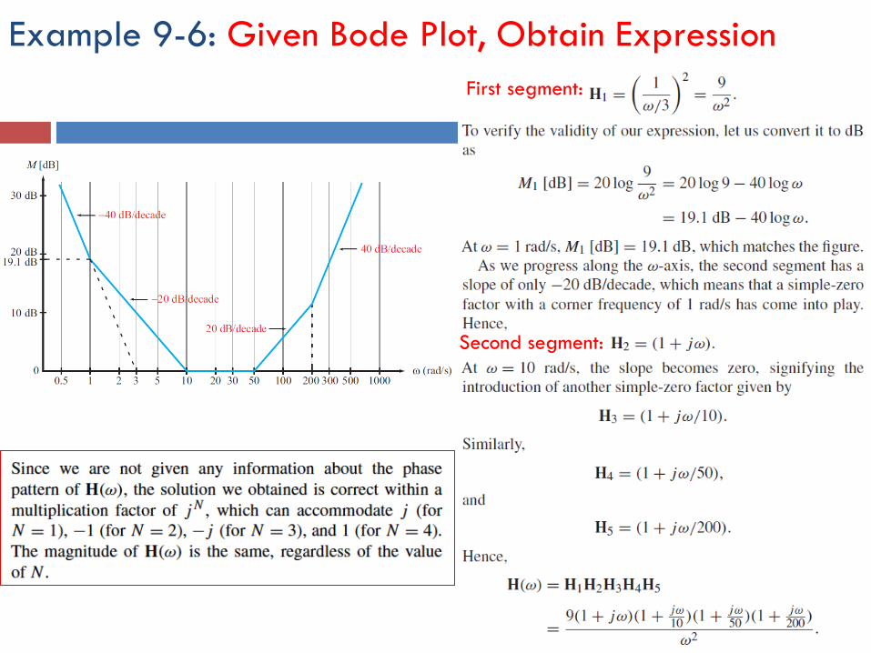
Example 9-6: Given Bode Plot, Obtain Expression
First segment:
Second segment:
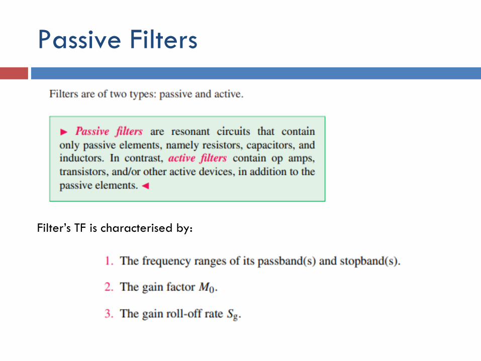
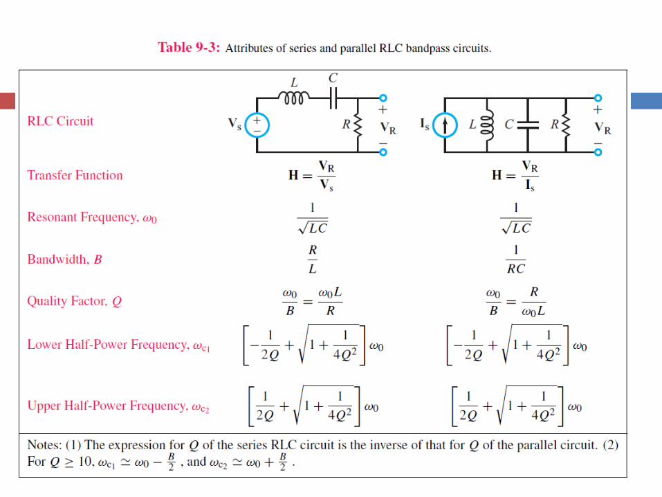
Passive Filters
Filter’s TF is characterised by:
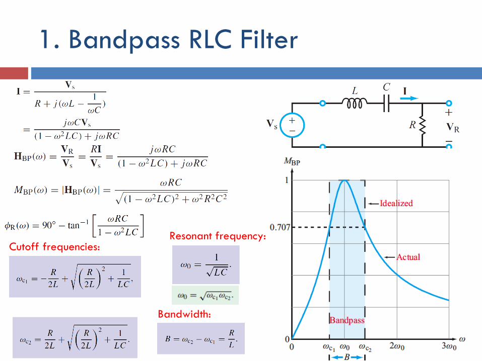
1. Bandpass RLC Filter
Resonant frequency:Cutoff frequencies:
Bandwidth:
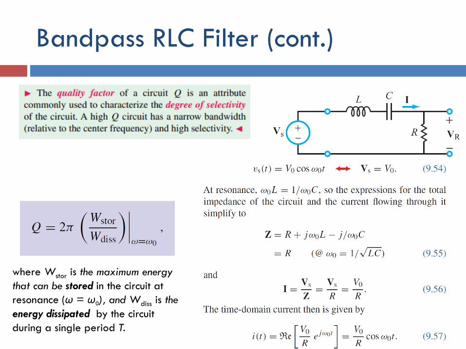
Bandpass RLC Filter (cont.)
where Wstor is the maximum energy
that can be stored in the circuit at
resonance (ω = ω0), and Wdiss is the
energy dissipated by the circuit
during a single period T.
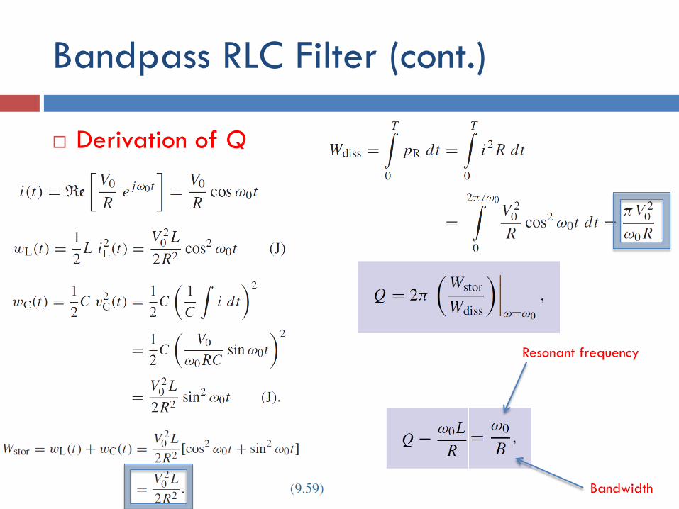
Bandpass RLC Filter (cont.)
Derivation of Q
Resonant frequency
Bandwidth
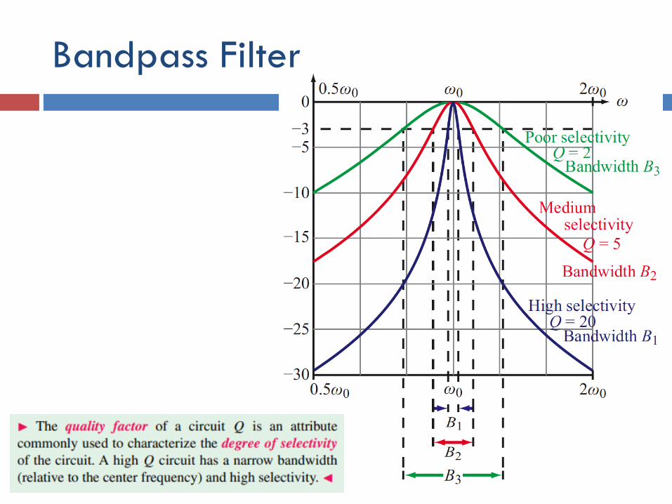
Bandpass Filter
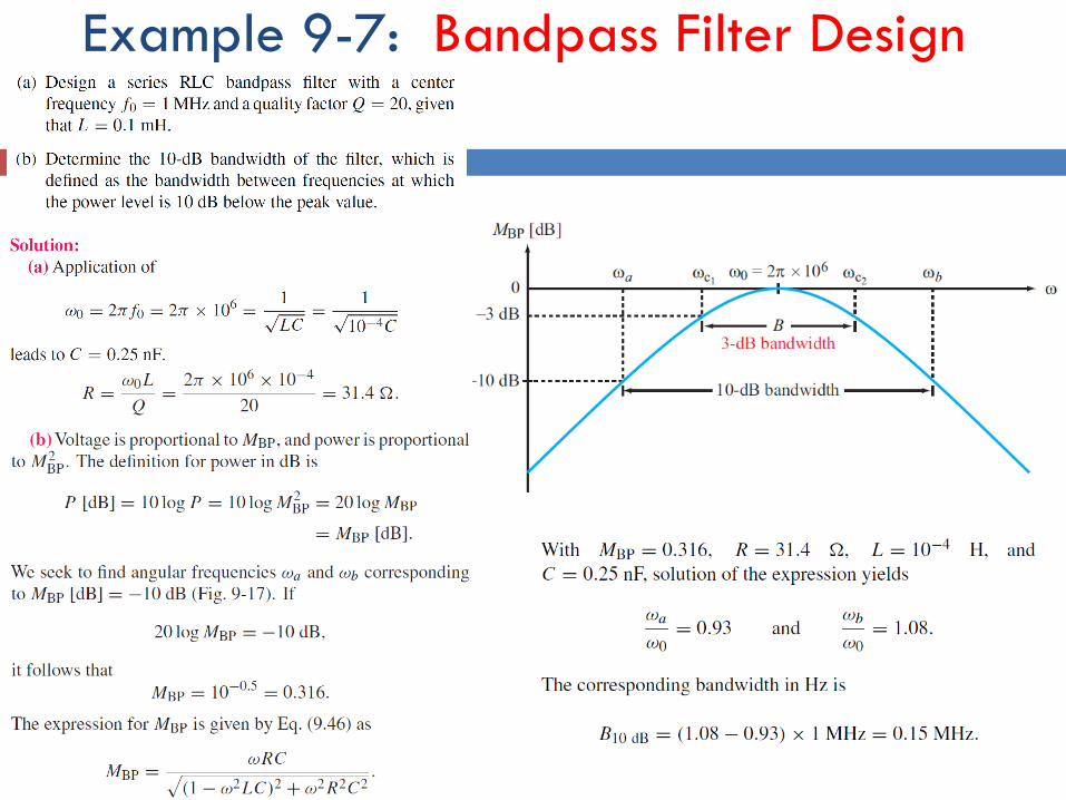
Example 9-7: Bandpass Filter Design
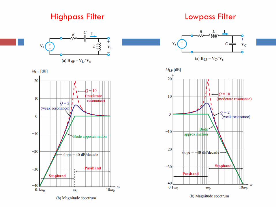
Highpass Filter Lowpass Filter
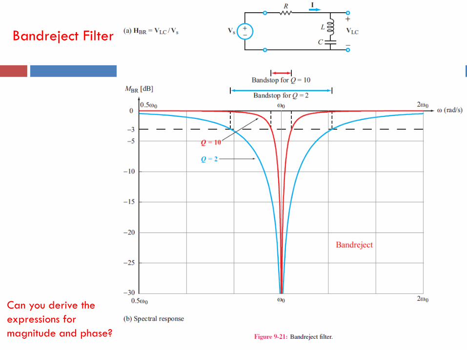
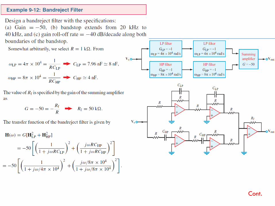
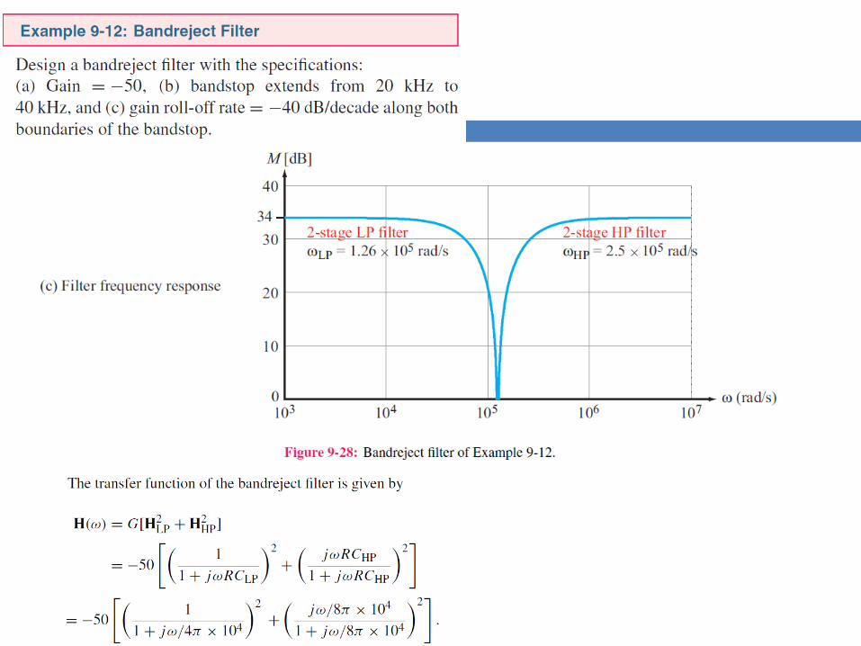
Bandreject Filter
Can you derive the
expressions for
magnitude and phase?
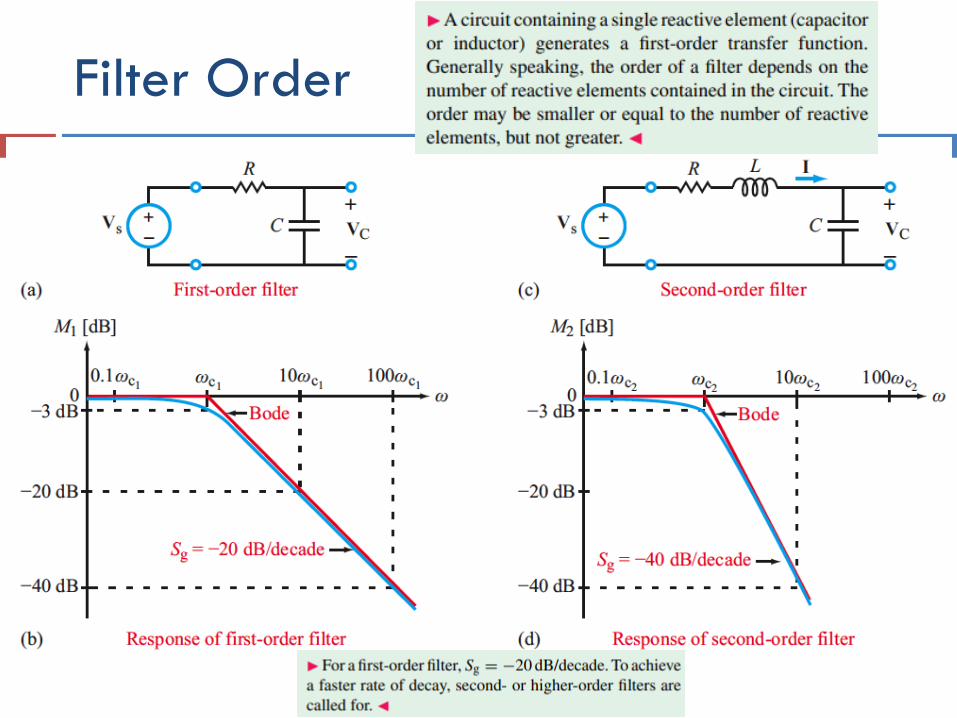
Filter Order
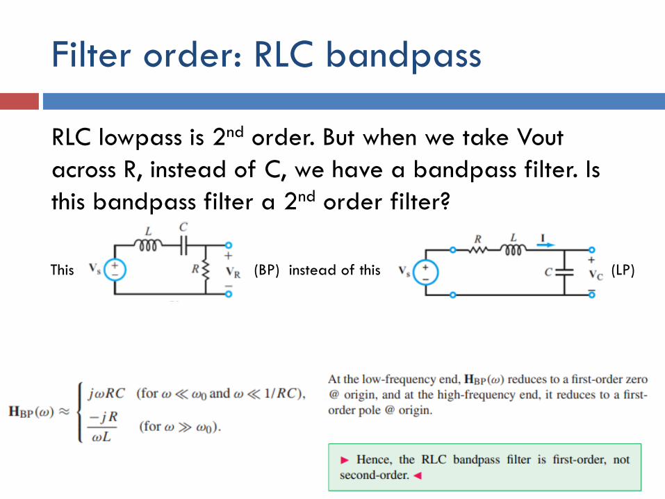
Filter order: RLC bandpass
RLC lowpass is 2nd order. But when we take Vout
across R, instead of C, we have a bandpass filter. Is
this bandpass filter a 2nd order filter?
This (BP) instead of this (LP)
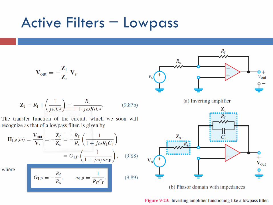
Active Filters ̶ Lowpass
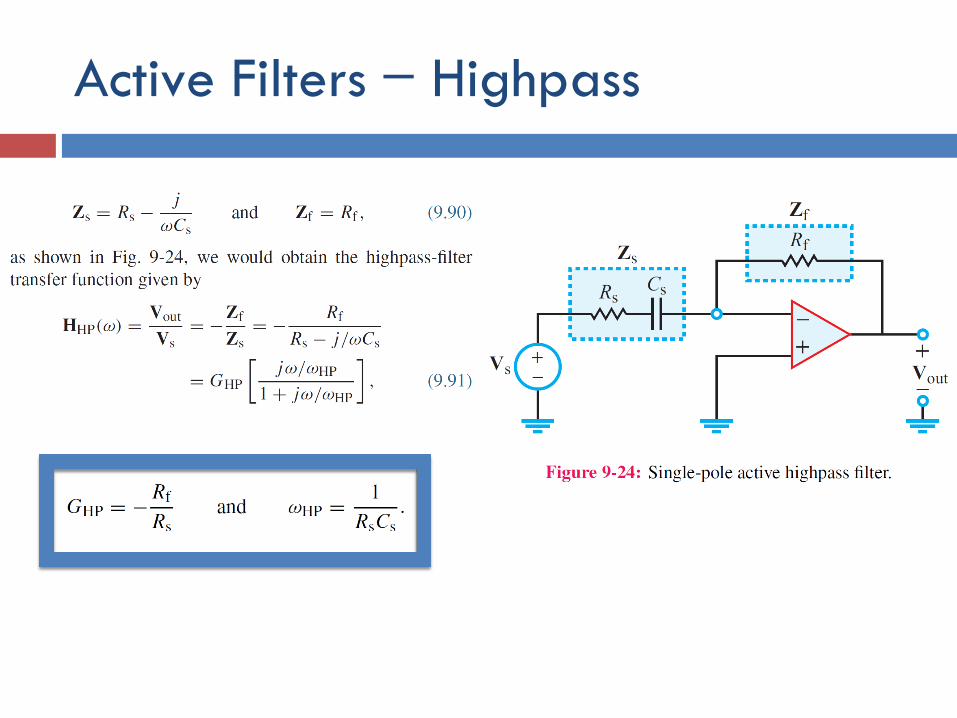
Active Filters ̶ Highpass
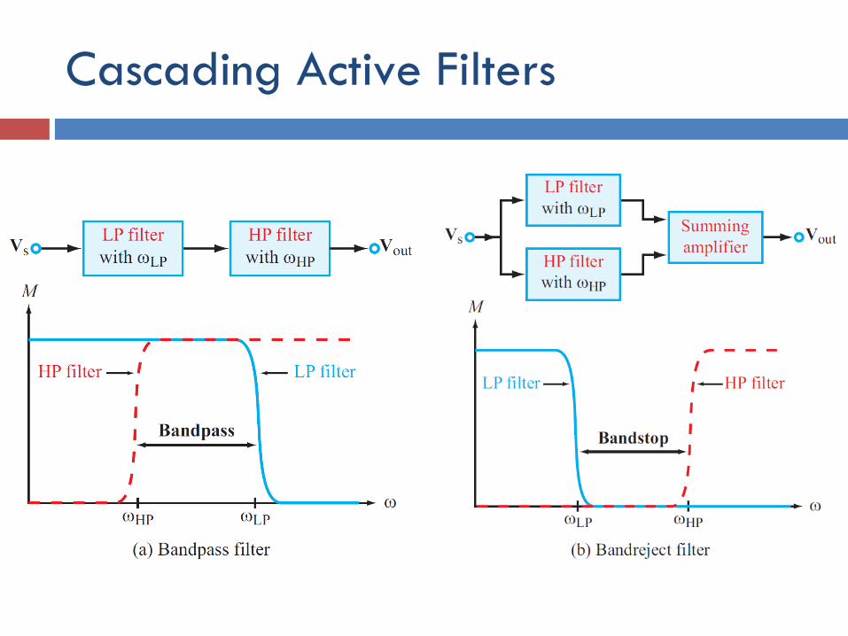
Cascading Active Filters
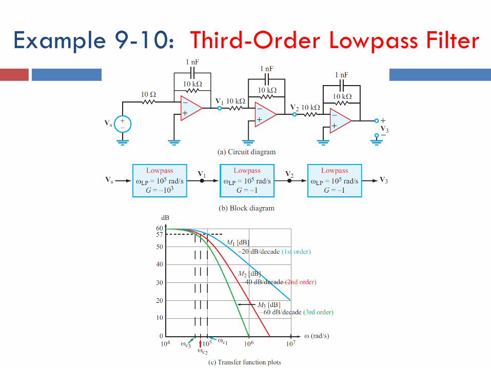
Example 9-10: Third-Order Lowpass Filter
Cont.
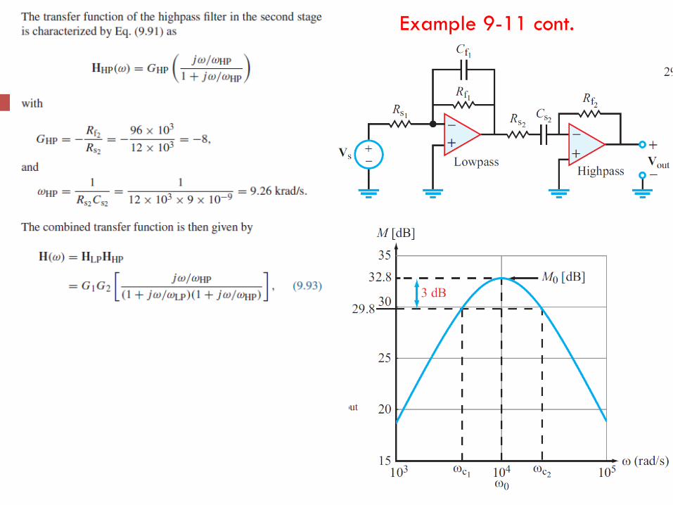
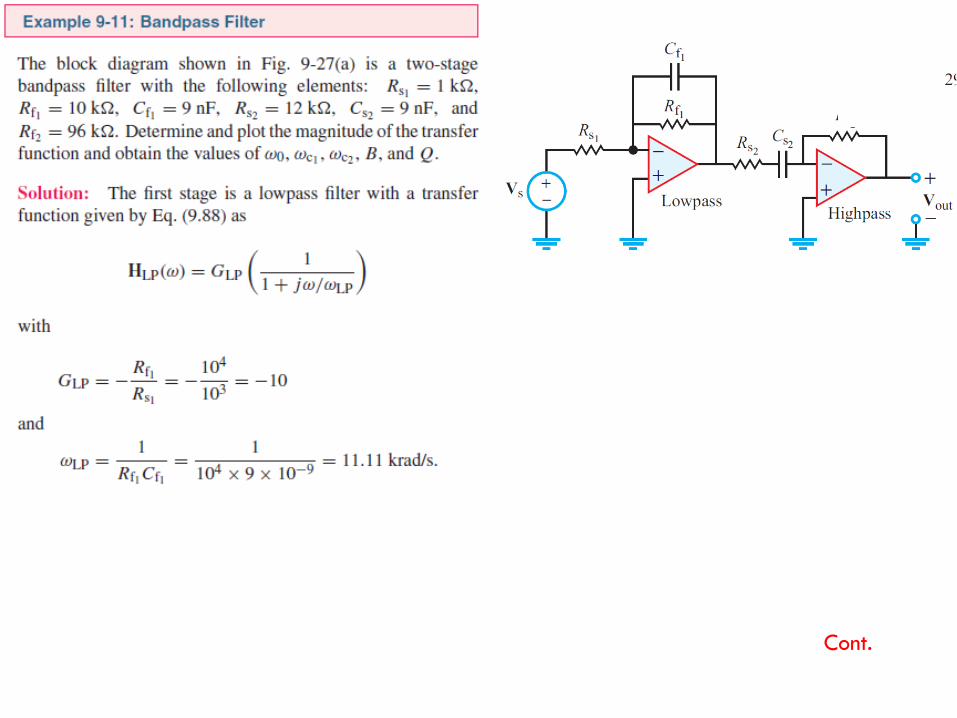
Example 9-11 cont.
Cont.
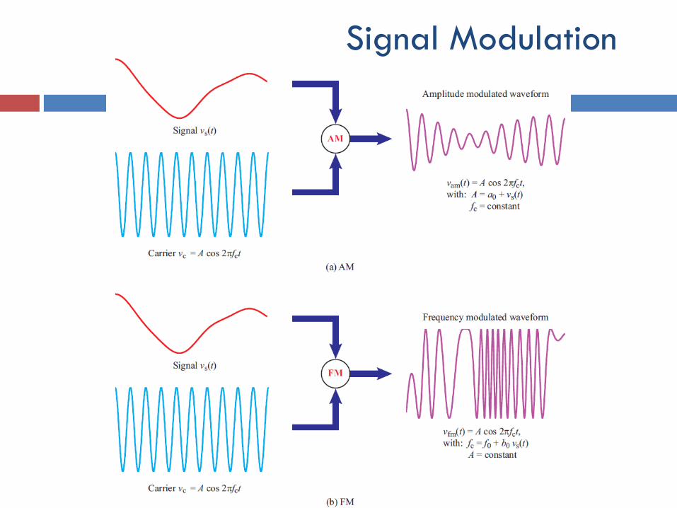
Signal Modulation
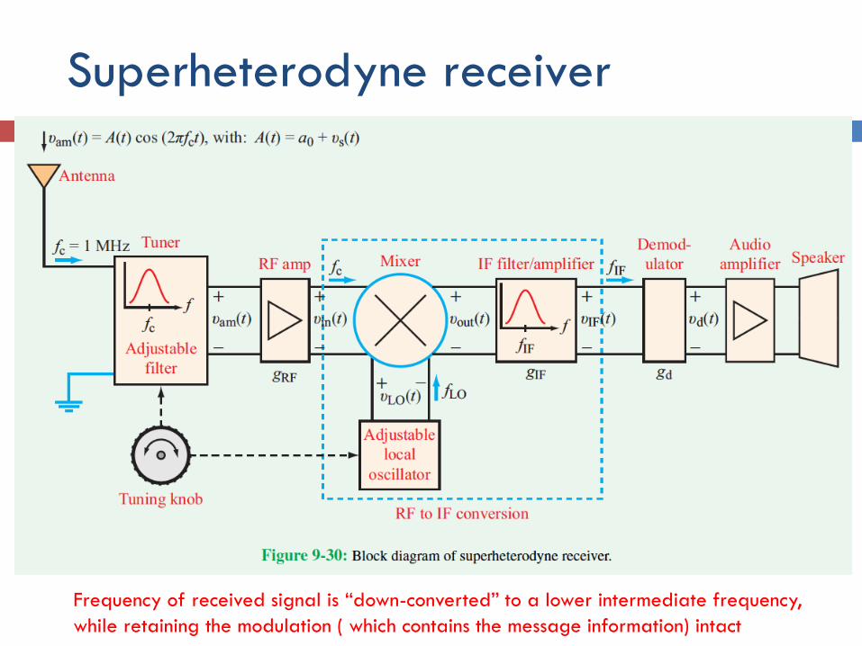
Superheterodyne receiver
Frequency of received signal is “down-converted” to a lower intermediate frequency,
while retaining the modulation ( which contains the message information) intact
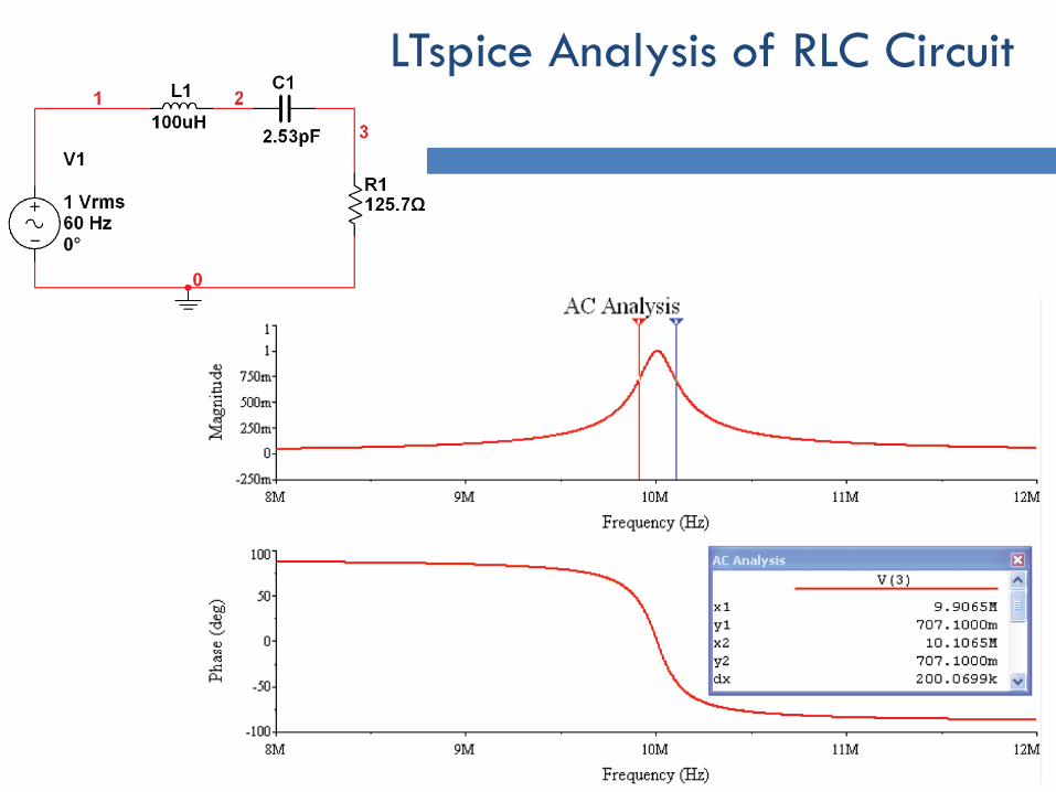
LTspice Analysis of RLC Circuit
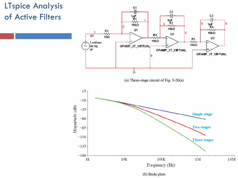
LTspice Analysis
of Active Filters
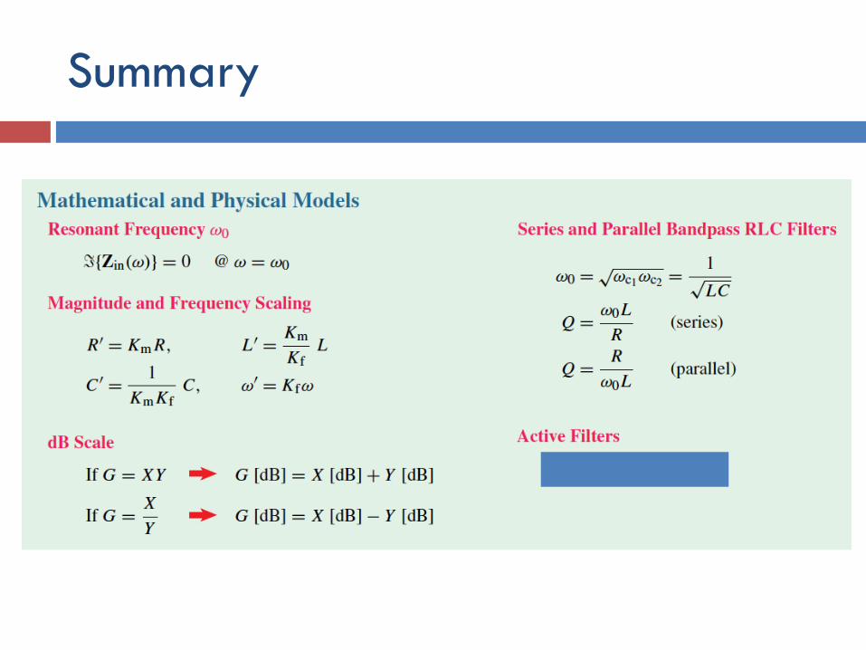
Summary