Large Stroke Electrostatic Comb-Drive Actuators Enabled by ... · OLFATNIAet al.:LARGE STROKE...
12
JOURNAL OF MICROELECTROMECHANICAL SYSTEMS, VOL. 22, NO. 2, APRIL 2013 483 Large Stroke Electrostatic Comb-Drive Actuators Enabled by a Novel Flexure Mechanism Mohammad Olfatnia, Siddharth Sood, Jason J. Gorman, Member, IEEE, and Shorya Awtar, Member, ASME Abstract—This paper presents in-plane electrostatic comb-drive actuators with stroke as large as 245 μm that is achieved by em- ploying a novel clamped paired double parallelogram (C-DP-DP) flexure mechanism. The C-DP-DP flexure mechanism design offers high bearing direction stiffness K x while maintaining low motion direction stiffness K y over a large range of motion direction displacement. The resulting high (K x /K y ) ratio mitigates the onset of sideways snap-in instability, thereby offering significantly greater actuation stroke compared with existing designs. Further improvement is achieved by reinforcing the individual beams in this flexure mechanism. While the traditional paired double parallelogram (DP-DP) flexure design with comb gap G =3 μm and flexure beam length L 1 =1 mm results in a 50-μm stroke before snap-in, the reinforced C-DP-DP design with the same comb gap and flexure beam length achieves a stroke of 141 μm. Furthermore, this C-DP-DP flexure design provides a 215-μm stroke with G =4 μm and a 245-μm stroke with G =6 μm. The presented work includes closed-form stiffness expressions for the reinforced C-DP-DP flexure, a design procedure for selecting dimensions of the overall comb-drive actuator, microfabrication of some representative actuators, and experimental measurements demonstrating the large stroke. [2012-0067] Index Terms—Comb drive, electrostatic actuator, flexure mech- anism, large stroke. I. I NTRODUCTION AND BACKGROUND E LECTROSTATIC microelectromechanical systems (MEMS) comb-drive actuators have been used in various applications such as resonators [1], filters [2], microgrippers [3], [4], and micro/nano positioning [5], [6]. A linear in-plane electrostatic comb-drive actuator comprises two electrically isolated conductive combs with N fingers each, schematically shown in Fig. 1. While the static comb is fixed with respect to ground, the moving comb is guided via a flexure mechanism so that it can displace primarily in the Y-direction with respect to the static comb. These static and moving comb fingers (length Manuscript received March 15, 2012; revised October 19, 2012; accepted October 24, 2012. Date of publication December 12, 2012; date of current ver- sion March 29, 2013. This work was supported in part by the National Science Foundation under Grant CMMI-0846738. The work of S. Sood was supported by the National Institute of Science and Technology under a Measurement Science and Engineering Graduate Fellowship. The experimental portion of this work was performed at the Lurie Nanofabrication Facility, a member of the National Nanotechnology Infrastructure Network, which is supported in part by the National Science Foundation. Subject Editor L. Lin. M. Olfatnia, S. Sood, and S. Awtar (corresponding author) are with the Department of Mechanical Engineering, University of Michigan, Ann Arbor, MI 48105 USA (e-mail: [email protected]; [email protected]; awtar@ umich.edu). J. J. Gorman is with the Engineering Laboratory, National Institute of Standards and Technology, Gaithersburg, MD 20899 USA (e-mail: gorman@ nist.gov). Color versions of one or more of the figures in this paper are available online at http://ieeexplore.ieee.org. Digital Object Identifier 10.1109/JMEMS.2012.2227458 Fig. 1. Schematic of an electrostatic comb drive with the springs representing the flexure bearing. L f , in-plane thickness T f , and out-of-plane thickness H f ) have an interdigitation gap of G and an initial engagement of Y o . The flexure mechanism is designed to provide linear guided motion and relatively small stiffness K y in the Y-direction (or motion direction), along with minimal error motions E x and relatively high stiffness K x in the X-direction (or bearing direction). In an ideal scenario, K y and E x would approach zero while K x would approach infinity. However, in practice, this is never the case given the performance tradeoffs between motion range, stiffness, and error motions that exist in flexure mechanisms [7], and manufacturing imperfections that are inherent to microfabrication processes [8], [9]. High stiffness K θ and low error motion E θ are also desirable in the in-plane yaw rotation [10]. Since K θ can be independently made large and E θ is inherently zero for the flexure designs considered here, in-plane rotation is initially ignored. The three out-of-plane directions are also bearing directions, but by appropriate choice of dimensions, become noncritical in the overall performance of the in-plane comb-drive actuator [11]. When a voltage difference V is applied between the two combs, they experience an electrostatic attractive force, which displaces the moving comb by Y along the motion direction K y · Y = εNH f G G 2 − X 2 V 2 . (1) Here, ε is the dielectric constant of air. Nonzero bearing direction displacement X can arise due to flexure error motion, fabrication misalignment, electrostatic forces, or a possible disturbance force in the X-direction. While displacement Y is dictated by the comb geometry, motion direction flexure stiffness, and actuation voltage, its maximum stroke is limited by the snap-in phenomenon, which corresponds to sideways 1057-7157/$31.00 © 2012 IEEE
Transcript of Large Stroke Electrostatic Comb-Drive Actuators Enabled by ... · OLFATNIAet al.:LARGE STROKE...
JOURNAL OF MICROELECTROMECHANICAL SYSTEMS, VOL. 22, NO. 2, APRIL 2013 483
Large Stroke Electrostatic Comb-Drive ActuatorsEnabled by a Novel Flexure Mechanism
Mohammad Olfatnia, Siddharth Sood, Jason J. Gorman, Member, IEEE, and Shorya Awtar, Member, ASME
Abstract—This paper presents in-plane electrostatic comb-driveactuators with stroke as large as 245 μm that is achieved by em-ploying a novel clamped paired double parallelogram (C-DP-DP)flexure mechanism. The C-DP-DP flexure mechanism design offershigh bearing direction stiffness Kx while maintaining low motiondirection stiffness Ky over a large range of motion directiondisplacement. The resulting high (Kx/Ky) ratio mitigates theonset of sideways snap-in instability, thereby offering significantlygreater actuation stroke compared with existing designs. Furtherimprovement is achieved by reinforcing the individual beamsin this flexure mechanism. While the traditional paired doubleparallelogram (DP-DP) flexure design with comb gap G = 3 μmand flexure beam length L1 = 1 mm results in a 50-μm strokebefore snap-in, the reinforced C-DP-DP design with the samecomb gap and flexure beam length achieves a stroke of 141 μm.Furthermore, this C-DP-DP flexure design provides a 215-μmstroke with G = 4 μm and a 245-μm stroke with G = 6 μm.The presented work includes closed-form stiffness expressions forthe reinforced C-DP-DP flexure, a design procedure for selectingdimensions of the overall comb-drive actuator, microfabricationof some representative actuators, and experimental measurementsdemonstrating the large stroke. [2012-0067]
Index Terms—Comb drive, electrostatic actuator, flexure mech-anism, large stroke.
I. INTRODUCTION AND BACKGROUND
E LECTROSTATIC microelectromechanical systems(MEMS) comb-drive actuators have been used in various
applications such as resonators [1], filters [2], microgrippers[3], [4], and micro/nano positioning [5], [6]. A linear in-planeelectrostatic comb-drive actuator comprises two electricallyisolated conductive combs with N fingers each, schematicallyshown in Fig. 1. While the static comb is fixed with respect toground, the moving comb is guided via a flexure mechanism sothat it can displace primarily in the Y-direction with respect tothe static comb. These static and moving comb fingers (length
Manuscript received March 15, 2012; revised October 19, 2012; acceptedOctober 24, 2012. Date of publication December 12, 2012; date of current ver-sion March 29, 2013. This work was supported in part by the National ScienceFoundation under Grant CMMI-0846738. The work of S. Sood was supportedby the National Institute of Science and Technology under a MeasurementScience and Engineering Graduate Fellowship. The experimental portion ofthis work was performed at the Lurie Nanofabrication Facility, a member of theNational Nanotechnology Infrastructure Network, which is supported in part bythe National Science Foundation. Subject Editor L. Lin.
M. Olfatnia, S. Sood, and S. Awtar (corresponding author) are with theDepartment of Mechanical Engineering, University of Michigan, Ann Arbor,MI 48105 USA (e-mail: [email protected]; [email protected]; [email protected]).
J. J. Gorman is with the Engineering Laboratory, National Institute ofStandards and Technology, Gaithersburg, MD 20899 USA (e-mail: [email protected]).
Color versions of one or more of the figures in this paper are available onlineat http://ieeexplore.ieee.org.
Digital Object Identifier 10.1109/JMEMS.2012.2227458
Fig. 1. Schematic of an electrostatic comb drive with the springs representingthe flexure bearing.
Lf , in-plane thickness Tf , and out-of-plane thickness Hf ) havean interdigitation gap of G and an initial engagement of Yo. Theflexure mechanism is designed to provide linear guided motionand relatively small stiffness Ky in the Y-direction (or motiondirection), along with minimal error motions Ex and relativelyhigh stiffness Kx in the X-direction (or bearing direction). Inan ideal scenario, Ky and Ex would approach zero while Kx
would approach infinity. However, in practice, this is never thecase given the performance tradeoffs between motion range,stiffness, and error motions that exist in flexure mechanisms[7], and manufacturing imperfections that are inherent tomicrofabrication processes [8], [9]. High stiffness Kθ andlow error motion Eθ are also desirable in the in-plane yawrotation [10]. Since Kθ can be independently made large andEθ is inherently zero for the flexure designs considered here,in-plane rotation is initially ignored. The three out-of-planedirections are also bearing directions, but by appropriate choiceof dimensions, become noncritical in the overall performanceof the in-plane comb-drive actuator [11].
When a voltage difference V is applied between the twocombs, they experience an electrostatic attractive force, whichdisplaces the moving comb by Y along the motion direction
Ky · Y =εNHfG
G2 −X2V 2. (1)
Here, ε is the dielectric constant of air. Nonzero bearingdirection displacement X can arise due to flexure error motion,fabrication misalignment, electrostatic forces, or a possibledisturbance force in the X-direction. While displacement Yis dictated by the comb geometry, motion direction flexurestiffness, and actuation voltage, its maximum stroke is limitedby the snap-in phenomenon, which corresponds to sideways
1057-7157/$31.00 © 2012 IEEE
484 JOURNAL OF MICROELECTROMECHANICAL SYSTEMS, VOL. 22, NO. 2, APRIL 2013
instability of the moving comb [12], [13]. For any Y dis-placement, the electrostatic force due to the actuation voltageV produces a destabilizing or negative spring effect and theflexure mechanism offers a stabilizing or positive spring effectin the X-direction. The former increases with increasing stroke,whereas the latter generally reduces. At the Y displacementwhen the former stiffness exceeds the latter, the moving combsnaps sideways into the static comb. This condition may bemathematically expressed as [12], [14]
(Kx
Ky
)≤ 2Y (Y +Y0)
G2
(1+ 3X2
c
G2
)(1−X2
c
G2
)2 , where Ex=4X3
c
G2 + 3X2c
. (2)
This snap-in condition assumes that the comb fingers areperfectly rigid and all compliance comes from the flexuremechanism. Moreover, the yaw rotational stiffness Kθ of theflexure mechanism is assumed large enough to be ignored. Theright-hand side represents a “critical stiffness ratio” needed toavoid snap-in and clearly increases with displacement Y anderror motion Ex. Ex includes any motion or misalignment ofthe moving comb in the X-direction with respect to its nominalzero position due to flexure mechanics or fabrication imper-fections, in the absence of electrostatic force. Here, Xc is theactual X-direction displacement at the onset of an electrostaticsnap-in when an error or misalignment Ex is present. Clearly,to delay snap-in and maximize the actuator stroke, the flexuremechanism should provide a high (Kx/Ky) ratio and low Ex
that are maintained over a large Y displacement range. Giventhe uncertainty in Ex from fabrication imperfections, its effectmay be incorporated via a positive stability margin S. Stableoperation is given by(
Kx
Ky
)≥ 2Y (Y + Y0)
G2(1 + S),
where S =
(1 +
3X2c
G2
)/(1− X2
c
G2
)2
− 1. (3)
From (2), it can be shown that for an error motion that is16% of the comb gap (e.g., Ex = 0.64 μm and G = 4 μm), astability margin of 1 is required.
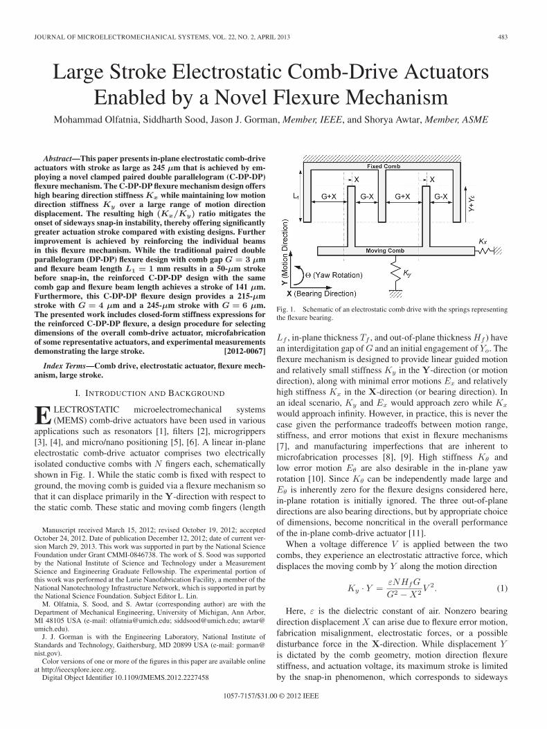
Large actuation stroke (> 100 μm) with limited footprintand actuation effort is desirable in a wide range of MEMS ap-plications, including optical switches [12], data-storage systems[15], high-resolution microprinting [16], [17], endoscopic mi-croscopy [18], neural microelectrodes [19], and scanning probemicroscopy [5]. The broad goal of this paper is to investigateand overcome the fundamental limits in flexure mechanismdesign to maximize the stroke of MEMS comb-drive actuatorswhile minimizing the device footprint and actuation voltage,for any given application. To meet this goal, we introducea novel flexure mechanism, i.e., the clamped paired doubleparallelogram (C-DP-DP) flexure, shown in Fig. 2.
Section II provides a review of the prior art on flexure mecha-nism designs that have been traditionally used with comb-driveactuators and their limitations. The proposed C-DP-DP flexuremechanism, which offers a high (Kx/Ky) ratio over a largeY displacement range, is presented in Section III, along withclosed-form analytical expressions for its stiffness. Section IV
Fig. 2. Clamped paired double parallelogram (C-DP-DP) flexure.
Fig. 3. Parallelogram (P) flexure.
outlines a step-by-step recipe to optimally select the dimensionsof this flexure mechanism and the comb drive to design anactuator with large stroke while minimizing actuation voltageand device footprint. Microfabrication of some representativeactuators and experimental results are elaborated in Section V.Using the C-DP-DP flexure, a maximum actuation stroke of245 μm with a 1-mm flexure beam length and a 6-μm combgap is demonstrated.
II. PRIOR ART
Some of the earliest flexure designs used in comb-drive ap-plications include the crab-leg flexure [13] and the folded-beamflexure [20], but both have limitations. While the former ex-hibits a Ky stiffness value that considerably grows with Y dis-placement, the latter provides a suboptimal Kx stiffness valuethat further deteriorates with increasing Y displacement [11].
The parallelogram (P) flexure, as shown in Fig. 3, is acommon single-axis flexure mechanism and serves as an
OLFATNIA et al.: LARGE STROKE ELECTROSTATIC COMB-DRIVE ACTUATORS ENABLED BY A NOVEL MECHANISM 485
important building block in other flexure mechanisms that havebeen widely used in comb-drive actuators in the past and inthe new flexure mechanism presented in this paper. Therefore,it is discussed in further detail here. In the P flexure shown inFig. 3, a general shape is assumed for each constituent beam,with two equal end segments having uniform thickness T1 andlength a0L1 and a rigid middle section of length (1− 2a0)L1.Geometric parameter a0 quantifies the degree of distributedcompliance: a0 = 1/2 represents a uniform thickness beamwith highly distributed compliance, whereas smaller valuesof a0 correspond to increasingly lumped compliance. Inthe subsequent discussion, a0 serves as a geometric shapeoptimization parameter.
Closed-form nonlinear stiffness and error motion relationsfor this flexure have been previously derived [7] and are sum-marized here
Ky =2EI1L31
k(0)11 (4)
Kx =2EI1L31
k33(1 + k33g
(1)11
(YL1
)2) (5)
Kθ =2EI1L31
·W 2 · k33(1 + k33g
(1)11
(YL1
)2) (6)
Ex = − k(1)11
2
Y 2
L1(7)
Eθ =k(0)11
2W 2
(Y
L1
)(1
k33+ g
(1)11
(Y
L1
)2). (8)
Here, E is the Young’s modulus of the material, and I1 isthe second moment of area (= H1T
31 /12). Nondimensional
terms k(0)11 , k(1)11 , g(1)11 , and k33 are all functions of the beam
shape (ao and T1) and are referred to as beam characteristiccoefficients [21]. These are graphically illustrated in Fig. 3 andmathematically expressed as follows:
k(0)11 =
6
(3− 6ao + 4a2o) ao
k(1)11 =
3(15− 50ao + 60a2o − 24a3o
)5 (3− 6ao + 4a2o)
2
g(1)11 =
2a3o(105− 630ao + 1440a2o − 1480a3o + 576a4o
)175 (3− 6ao + 4a2o)
3
k33 =6
a0(T1/L1)2. (9)
Per (4), the P flexure provides low Ky stiffness that remains
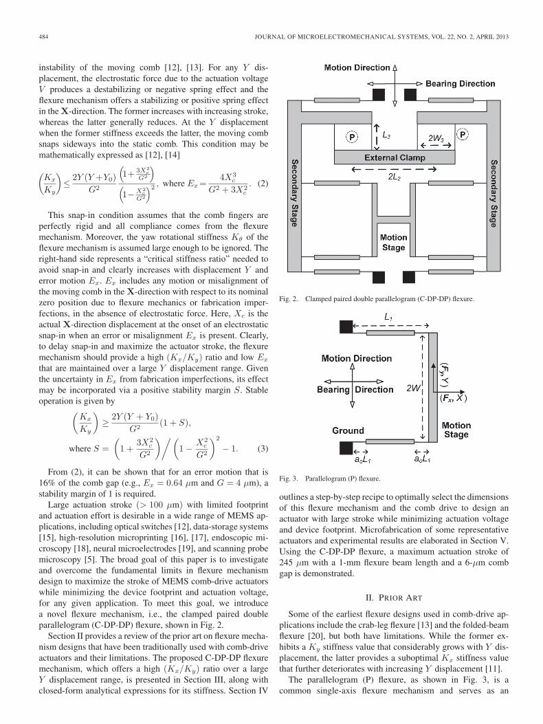
constant with Y and depends directly on coefficient k(0)11 . k(0)11 ,which corresponds to the normalized elastic stiffness of anindividual beam in the Y-direction, is insensitive to valuesof a0 around 0.5 but significantly grows as ao decreases [seeFig. 4(b)]. Per (5), this flexure also provides high Kx stiffnessat Y = 0, which depends on coefficient k33. k33 is the nominalelastic stiffness of an individual beam in the X-direction nor-malized with respect to its bending stiffness and also increaseswith reducing a0 [see Fig. 4(a)].
Fig. 4. Beam characteristic coefficients. For the k33 plot, (T1/L1) is as-sumed to be 0.003.
Furthermore, the stiffness Kx drops with increasing Y dis-placement due to the k33g
(1)11 term in the denominator of (5).
Specifically, coefficient g(1)11 captures the elastokinematic effectin an individual beam that contributes additional X-directioncompliance in the presence of a Y displacement, and ap-proaches zero with reducing a0 [see Fig. 4(b)]. Since the prod-uct k33g
(1)11 also approaches zero with reducing a0 (see Fig. 4),
the drop in Kx stiffness can be reduced by decreasing a0.As given by (6), the rotational stiffness Kθ of this flexure
mechanism follows a trend similar to Kx. However, the nomi-nal value of this stiffness can be independently increased to belarge enough by increasing the dimension W .
Thus, as evident in Fig. 6, the P flexure provides a favor-able Kx/Ky stiffness ratio that can be further optimized byreducing ao. However, the overwhelming disadvantage of thisflexure mechanism is its large error motion Ex that arises dueto the kinematics of beam arc-length conservation, which iscaptured via coefficient k(1)11 . Since this kinematic coefficientis fundamental to the geometry of the beam, it always remainsbetween 1 and 1.2, irrespective of the beam shape a0, as evidentin Fig. 4(a). The quadratic relation given by (7) shows thatthe motion stage in a P flexure follows a parabolic trajectoryinstead of a perfectly straight line. For typical beam dimensions(L1 = 1 mm and a0 = 0.5) and displacement Y = 0.1L1, theEx error motion is 6 μm, which is significant and would causevery early snap-in, as predicted by (2).
486 JOURNAL OF MICROELECTROMECHANICAL SYSTEMS, VOL. 22, NO. 2, APRIL 2013
One effective method to alleviate this issue without elim-inating Ex is to systematically prebend the beams of theP flexure, introduce an initial offset in the gap between the fixedand moving combs, and incline the comb fingers with respectto the Y -axis [22]. Grade et al. [23] implemented this cleveridea to demonstrate a 175-μm comb-drive actuator stroke usingL1 = 2 mm and asymmetric comb gaps of 6 and 9 μm. Whilesnap-in is thus mitigated, the trajectory of the motion stage isstill parabolic, which can be undesirable in certain applications.
In order to eliminate the above Ex error motion, one mightemploy two P flexures in a symmetric parallel configuration(P-P) [24]. However, this results in an overconstrained ge-ometry that produces a quadratic rise in the motion directionstiffness with increasing Y displacement and therefore a sig-nificantly restricted stroke. A more appropriate approach is touse two oppositely oriented P flexures in series. The resultingdouble parallelogram (DP) flexure employs the principle ofgeometric reversal to exactly cancel out the kinematic errormotion of one P with that of the other P, in the absence ofX-direction force, to produce Ex = 0. Next, employing twoDP flexures in parallel, as shown in Fig. 7, produces a sym-metrical geometry that ensures Eθ = 0 and reduced sensitivityto fabrication imperfections. In fact, the earliest reported comb-drive actuators employed the paired double parallelogram DP-DP flexure [1]. Subsequently, Legtenberg et al. [13] extensivelystudied this flexure for comb-drive actuation and reported a39.9-μm stroke with L1 = 500 μm and G = 2.2 μm.
Closed-form nonlinear stiffness relations for the DP-DP flex-ure have been also previously derived [7] and are summarizedhere
Ky =2EI1L31
k(0)11 (10)
Kx =2EI1L31
k33(1 + k33
(g(1)11 +
(k(1)11
)2
k(0)11
)(Y2L1
)2) (11)
Kθ =EI1L31
· 4W 21W
22
(W 21 +W 2
2 )· k33(
1 + k33g(1)11
(Y2L1
)2) . (12)
The motion direction stiffness Ky of the DP-DP flexure islow and remains largely invariant with Y displacement, i.e.,same as that of the P flexure. However, while its nominal Kx
stiffness at Y =0 is the same as that of the P flexure, the drop inKx with increasing Y displacement is far more precipitous. Thereason being that, in addition to the k33g
(1)11 term in the denom-
inator of (11), there is now a new term, i.e., (k(1)11 )2k33/k
(0)11 ,
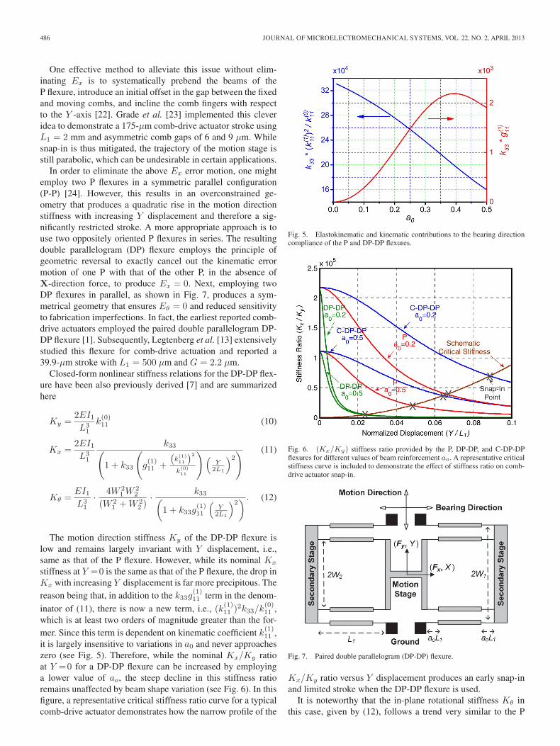
which is at least two orders of magnitude greater than the for-mer. Since this term is dependent on kinematic coefficient k(1)11 ,it is largely insensitive to variations in a0 and never approacheszero (see Fig. 5). Therefore, while the nominal Kx/Ky ratioat Y =0 for a DP-DP flexure can be increased by employinga lower value of ao, the steep decline in this stiffness ratioremains unaffected by beam shape variation (see Fig. 6). In thisfigure, a representative critical stiffness ratio curve for a typicalcomb-drive actuator demonstrates how the narrow profile of the
Fig. 5. Elastokinematic and kinematic contributions to the bearing directioncompliance of the P and DP-DP flexures.
Fig. 6. (Kx/Ky) stiffness ratio provided by the P, DP-DP, and C-DP-DPflexures for different values of beam reinforcement ao. A representative criticalstiffness curve is included to demonstrate the effect of stiffness ratio on comb-drive actuator snap-in.
Fig. 7. Paired double parallelogram (DP-DP) flexure.
Kx/Ky ratio versus Y displacement produces an early snap-inand limited stroke when the DP-DP flexure is used.
It is noteworthy that the in-plane rotational stiffness Kθ inthis case, given by (12), follows a trend very similar to the P
OLFATNIA et al.: LARGE STROKE ELECTROSTATIC COMB-DRIVE ACTUATORS ENABLED BY A NOVEL MECHANISM 487
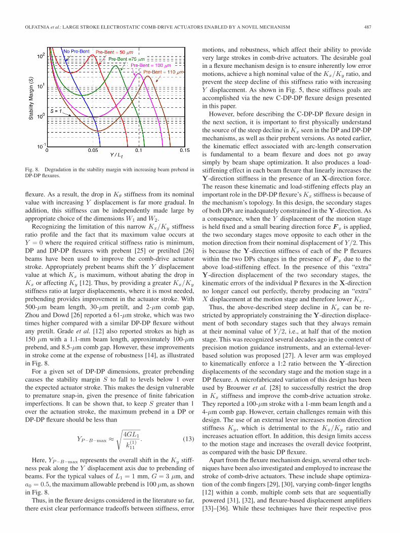
Fig. 8. Degradation in the stability margin with increasing beam prebend inDP-DP flexures.
flexure. As a result, the drop in Kθ stiffness from its nominalvalue with increasing Y displacement is far more gradual. Inaddition, this stiffness can be independently made large byappropriate choice of the dimensions W1 and W2.
Recognizing the limitation of this narrow Kx/Ky stiffnessratio profile and the fact that its maximum value occurs atY = 0 where the required critical stiffness ratio is minimum,DP and DP-DP flexures with prebent [25] or pretilted [26]beams have been used to improve the comb-drive actuatorstroke. Appropriately prebent beams shift the Y displacementvalue at which Kx is maximum, without abating the drop inKx or affecting Ky [12]. Thus, by providing a greater Kx/Ky
stiffness ratio at larger displacements, where it is most needed,prebending provides improvement in the actuator stroke. With500-μm beam length, 30-μm pretilt, and 2-μm comb gap,Zhou and Dowd [26] reported a 61-μm stroke, which was twotimes higher compared with a similar DP-DP flexure withoutany pretilt. Grade et al. [12] also reported strokes as high as150 μm with a 1.1-mm beam length, approximately 100-μmprebend, and 8.5-μm comb gap. However, these improvementsin stroke come at the expense of robustness [14], as illustratedin Fig. 8.
For a given set of DP-DP dimensions, greater prebendingcauses the stability margin S to fall to levels below 1 overthe expected actuator stroke. This makes the design vulnerableto premature snap-in, given the presence of finite fabricationimperfections. It can be shown that, to keep S greater than 1over the actuation stroke, the maximum prebend in a DP orDP-DP flexure should be less than
YP−B−max ≈√
4GL1
k(1)11
. (13)
Here, YP−B−max represents the overall shift in the Ky stiff-ness peak along the Y displacement axis due to prebending ofbeams. For the typical values of L1 = 1 mm, G = 3 μm, anda0 = 0.5, the maximum allowable prebend is 100 μm, as shownin Fig. 8.
Thus, in the flexure designs considered in the literature so far,there exist clear performance tradeoffs between stiffness, error
motions, and robustness, which affect their ability to providevery large strokes in comb-drive actuators. The desirable goalin a flexure mechanism design is to ensure inherently low errormotions, achieve a high nominal value of the Kx/Ky ratio, andprevent the steep decline of this stiffness ratio with increasingY displacement. As shown in Fig. 5, these stiffness goals areaccomplished via the new C-DP-DP flexure design presentedin this paper.
However, before describing the C-DP-DP flexure design inthe next section, it is important to first physically understandthe source of the steep decline in Kx seen in the DP and DP-DPmechanisms, as well as their prebent versions. As noted earlier,the kinematic effect associated with arc-length conservationis fundamental to a beam flexure and does not go awaysimply by beam shape optimization. It also produces a load-stiffening effect in each beam flexure that linearly increases theY-direction stiffness in the presence of an X-direction force.The reason these kinematic and load-stiffening effects play animportant role in the DP-DP flexure’s Kx stiffness is because ofthe mechanism’s topology. In this design, the secondary stagesof both DPs are inadequately constrained in the Y-direction. Asa consequence, when the Y displacement of the motion stageis held fixed and a small bearing direction force F x is applied,the two secondary stages move opposite to each other in themotion direction from their nominal displacement of Y/2. Thisis because the Y-direction stiffness of each of the P flexureswithin the two DPs changes in the presence of F x due to theabove load-stiffening effect. In the presence of this “extra”Y-direction displacement of the two secondary stages, thekinematic errors of the individual P flexures in the X-directionno longer cancel out perfectly, thereby producing an “extra”X displacement at the motion stage and therefore lower Kx.
Thus, the above-described steep decline in Kx can be re-stricted by appropriately constraining the Y-direction displace-ment of both secondary stages such that they always remainat their nominal value of Y/2, i.e., at half that of the motionstage. This was recognized several decades ago in the context ofprecision motion guidance instruments, and an external-lever-based solution was proposed [27]. A lever arm was employedto kinematically enforce a 1:2 ratio between the Y-directiondisplacements of the secondary stage and the motion stage in aDP flexure. A microfabricated variation of this design has beenused by Brouwer et al. [28] to successfully restrict the dropin Kx stiffness and improve the comb-drive actuation stroke.They reported a 100-μm stroke with a 1-mm beam length and a4-μm comb gap. However, certain challenges remain with thisdesign. The use of an external lever increases motion directionstiffness Ky , which is detrimental to the Kx/Ky ratio andincreases actuation effort. In addition, this design limits accessto the motion stage and increases the overall device footprint,as compared with the basic DP flexure.
Apart from the flexure mechanism design, several other tech-niques have been also investigated and employed to increase thestroke of comb-drive actuators. These include shape optimiza-tion of the comb fingers [29], [30], varying comb-finger lengths[12] within a comb, multiple comb sets that are sequentiallypowered [31], [32], and flexure-based displacement amplifiers[33]–[36]. While these techniques have their respective pros
488 JOURNAL OF MICROELECTROMECHANICAL SYSTEMS, VOL. 22, NO. 2, APRIL 2013
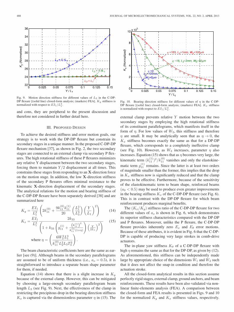
Fig. 9. Motion direction stiffness for different values of L3 in the C-DP-DP flexure [(solid line) closed-form analysis; (markers) FEA]. Ky stiffness isnormalized with respect to EI1/L3
1.
and cons, they are peripheral to the present discussion andtherefore not considered in further detail here.
III. PROPOSED DESIGN
To achieve the desired stiffness and error motion goals, ourstrategy is to work with the DP-DP flexure but constrain itssecondary stages in a unique manner. In the proposed C-DP-DPflexure mechanism [37], as shown in Fig. 2, the two secondarystages are connected to an external clamp via secondary P flex-ures. The high rotational stiffness of these P flexures minimizesany relative Y displacement between the two secondary stages,forcing them to maintain Y/2 displacement at all times. Thisconstrains these stages from responding to an X-direction forceon the motion stage. In addition, the low X-direction stiffnessof the secondary P flexures offers minimal resistance to thekinematic X-direction displacement of the secondary stages.The analytical relations for the motion and bearing stiffness ofthe C-DP-DP flexure have been separately derived [38] and aresummarized here
Ky =EI1L31
(2k
(0)11 +
9k(0)11 k
(1)11
20
(L31
L33
)(Y
L1
)2)
(14)
Kx =EI1L31
2k33(1 + k33
(g(1)11 +
(k(1)11
)2
k(0)11 (1+η)
)(Y2L1
)2) (15)
where η =
(6W 2
3L31
k(0)11 L
22L3T 2
3
).
The beam characteristic coefficients here are the same as ear-lier [see (9)]. Although beams in the secondary parallelogramsare assumed to be of uniform thickness (i.e., ao = 0.5), it isstraightforward to introduce a separate beam shape parameterfor them, if needed.
Equation (14) shows that there is a slight increase in Ky
because of the external clamp. However, this can be mitigatedby choosing a large-enough secondary parallelogram beamlength L3 (see Fig. 9). Next, the effectiveness of the clamp inrestricting the precipitous drop in the bearing direction stiffnessKx is captured via the dimensionless parameter η in (15). The
Fig. 10. Bearing direction stiffness for different values of η in the C-DP-DP flexure [(solid line) closed-form analysis; (markers) FEA]. Kx stiffnessis normalized with respect to EI1/L3
1.
external clamp prevents relative Y motion between the twosecondary stages by employing the high rotational stiffnessof its constituent parallelograms, which manifests itself in theform of η. For low values of W3, this stiffness and thereforeη are small. It may be analytically seen that as η → 0, theKx stiffness becomes exactly the same as that for a DP-DPflexure, which corresponds to a completely ineffective clamp(see Fig. 10). However, as W3 increases, parameter η alsoincreases. Equation (15) shows that as η becomes very large, thekinematic term (k
(1)11 )
2/k(0)11 vanishes and only the elastokine-
matic term g(1)11 remains. Since the latter is at least two orders
of magnitude smaller than the former, this implies that the dropin Kx stiffness now is significantly reduced and that the clampproves to be effective. Furthermore, because of the sensitivityof the elastokinematic term to beam shape, reinforced beams(a0 < 0.5) may be used to produce even greater improvementsin the bearing stiffness Kx of the C-DP-DP flexure (see Fig. 6).This is in contrast with the DP-DP flexure for which beamreinforcement produces marginal benefits.
The (Kx/Ky) stiffness ratio of the C-DP-DP flexure for twodifferent values of ao is shown in Fig. 6, which demonstratesits superior stiffness characteristics compared with the DP-DPand P flexures. Moreover, unlike the P flexure, the C-DP-DPflexure provides inherently zero Ex and Eθ error motions.Because of these attributes, it is evident in Fig. 6 that the C-DP-DP is capable of producing very large strokes in comb-driveactuators.
The in-plane yaw stiffness Kθ of a C-DP-DP flexure withhigh η remains the same as that for the DP-DP, as given by (12).As aforementioned, this stiffness can be independently madelarge by appropriate choice of the dimensions W1 and W2 suchthat it does not affect the snap-in condition and therefore theactuation stroke.
All the closed-form analytical results in this section assumeperfectly rigid stages, external clamp, ground anchors, and beamreinforcements. These results have been also validated via non-linear finite-elements analysis (FEA). A comparison betweenthe closed-form and FEA results is presented in Figs. 9 and 10for the normalized Ky and Kx stiffness values, respectively.
OLFATNIA et al.: LARGE STROKE ELECTROSTATIC COMB-DRIVE ACTUATORS ENABLED BY A NOVEL MECHANISM 489
The following dimensions were used to generate the resultsplotted in these figures: L1=1 mm, T1=5 μm, W1=250 μm,W2=400 μm, L2=1.1 mm, a0=0.5, and H1=50 μm; W3=250 μm, and L3 varies in Fig. 9; both L3 and W3 vary in Fig. 10.
IV. COMB-DRIVE ACTUATOR DESIGN RECIPE
In this section, we present a systematic procedure for design-ing a C-DP-DP flexure-based comb-drive actuator to maximizeits actuation stroke while minimizing device footprint andactuation voltage. In an actual application, one would take intoaccount any additional constraints imposed by that applicationin addition to the procedure and steps presented here.
Given the several constraints and tradeoffs involved, the goalhere is to obtain a good starting point for the flexure andcomb-drive dimensions (i.e., L1, T1, a0, W1, W2, L2, L3, W3,G, Lf , and Tf ) based on some simplifying assumptions andsubsequently iterate to further refine the overall design.
The following assumptions are initially made and are revis-ited during later design steps.
1) Analytical results in the previous section show that theoptimization of the external clamp and secondary par-allelograms is decoupled from the final stiffness of theC-DP-DP flexure, as long as the clamp is effective. Sincean optimal clamp that provides high η can always becreated subsequently, motion and bearing stiffness valuescorresponding to high η(→ ∞) are assumed at the onsetof this design procedure, i.e.,
Ky =2EI1k
(0)11
L31
(16)
Kx =2EI1L31
k33(1 + k33g
(1)11
(Y2L1
)2) . (17)
2) The motion stage, secondary stage, external clamp,ground anchors, and beam reinforcements are all assumedto be perfectly rigid.
3) Since the in-plane rotational stiffness Kθ of the C-DP-DP flexure can be made independently high, it is assumedlarge enough to be ignored in the first iteration.
4) Although the C-DP-DP flexure exhibits theoretically zeroerror motions in the X- and Θ-directions because of itsinherent symmetry, misalignment and error motions dueto fabrication imperfection are inevitable. Therefore, astability margin of S = 1 is assumed to provide robust-ness against such nondeterministic factors. This may haveto be revised in subsequent iterations.
5) Silicon is chosen as the flexure and comb-drive material,which sets an upper bound for the maximum achievablestroke due to mechanical failure. For the C-DP-DP flex-ure, the yield limit is given by [7]
Yyield ≤(
8
k(0)11
)(Sy
E
)(L21
T1
)(18)
where Sy is the material yield strength.
6) An initial comb-finger engagement Y0 is needed to over-come fringing effects that are important for small Ydisplacements. However, Y0 is much smaller than themaximum Y displacement and is therefore initiallydropped in the design procedure.
With these assumptions, one can now substitute the mo-tion and bearing direction stiffness expressions for an optimalC-DP-DP [see (16) and (17)] into the snap-in condition (3) fora comb-drive actuator
k33
k(0)11
(1 + k33g
(1)11
(Ymax
2L1
)2) =
4Y 2max
G2. (19)
This snap-in condition corresponds to maximum motiondirection displacement Ymax, which is also the actuation stroke,and associated stiffness values. The actuation voltage Vmax atthis maximum displacement may be obtained from (1), i.e.,
NV 2max =
E
6
(T1
L1
)3k(0)11 YmaxG
ε. (20)
The left-hand side in the above equation represents theactuation effort, which should generally be minimized. LowerN helps reduce the device footprint, and Vmax is often restrictedby practical instrumentation and operational limits.
As aforementioned, k(0)11 , g(1)11 , and k33 are all functions of aoand (T1/L1), as given by (9). We next present a step-by-steprecipe for choosing the dimensions of the C-DP-DP and combdrive that employs the analytical knowledge compiled so far.
−−−−−−−−−Step 1: Start with assuming a dimension for the flexure beamlength L1, which directly impacts the device footprint. In thefirst iteration, we choose an initial L1 value of 1 mm.
−−−−−−−−−Step 2: Minimizing the T1/L1 ratio lowers the actuation effort[see (20)] and reduces the bending stress in the flexure beams.A smaller T1/L1 ratio also increases the left-hand side of (19),thus delaying the snap-in condition. Therefore, the flexure beamthickness should be chosen to be a small value dictated by thepractical limits of the microfabrication process. As mentionedin the next section, this limit is 1.7 μm in our case, andwith an adequate safety margin, we choose T1 = 3 μm, whichcorresponds to a T1/L1 ratio of 0.003.
−−−−−−−−−Step 3: Now, the two key remaining design variables in (19) and(20) are a0 and G. These two equations may be simultaneouslysolved to eliminate G to produce:
NV 2max=
E
3ε
(T1
L1
)3
Y 2max
√√√√(k(0)11
)3[
1
k33+
(Ymax
2L
)2
g(1)11
].
(21)
The above condition can be plotted on an NV 2max versus Ymax
graph for multiple fixed values of a0 (see Fig. 11). Each solidline, referred to an iso−a0 line, represents a fixed value of a0and varying values of G. Similarly, the above equations aresolved to eliminate ao, and the resulting condition is plotted onthe same NV 2
max versus Ymax graph for fixed values of G. Eachdashed line, referred to an iso−G line, represents a fixed valueof G and varying values of a0. Moving along an iso−a0 line, itis clear that for a given beam shape a0, one can achieve higherstroke by increasing the comb gap G, but this also increases
490 JOURNAL OF MICROELECTROMECHANICAL SYSTEMS, VOL. 22, NO. 2, APRIL 2013
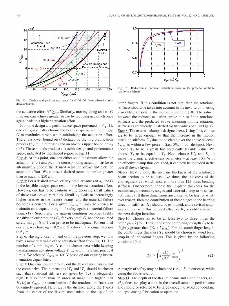
Fig. 11. Design and performance space for C-DP-DP flexure-based comb-drive actuators.
the actuation effort NV 2max. Similarly, moving along an iso−G
line, one can achieve greater stroke by reducing a0, which onceagain leads to a higher actuation effort.
From the design and performance space presented in Fig. 11,one can graphically choose the beam shape a0 and comb gapG to maximize stroke while minimizing the actuation effort.There is a lower bound on G dictated by the microfabricationprocess (2 μm, in our case) and an obvious upper bound on a0(0.5). These bounds produce a feasible design and performancespace, indicated by the shaded region in Fig. 11.
−−−−−−−−−Step 4: At this point, one can either set a maximum allowableactuation effort and pick the corresponding actuation stroke oralternatively choose the desired actuation stroke and pick theactuation effort. We choose a desired actuation stroke greaterthan or equal to 250 μm.
−−−−−−−−−Step 5: For a desired stroke, clearly, smaller values of ao and Gin the feasible design space result in the lowest actuation effort.However, one has to be cautious while choosing small valuesof these two design variables. Small ao leads to increasinglyhigher stresses in the flexure beams, and the material failurebecomes a concern. For a given Ymax, a0 may be chosen tomaintain an adequate margin of safety against material failureusing (18). Separately, the snap-in condition becomes highlysensitive to error motions Ex for very small G, and the assumedsafety margin S of 1 can prove to be inadequate. For our finaldesigns, we chose a0 = 0.2 and G values in the range of 3 μmto 6 μm.
−−−−−−−−−Step 6: Having chosen ao and G in the previous step, we nowhave a numerical value of the actuation effort from Fig. 11. Thenumber of comb fingers N can be chosen next while keepingthe maximum actuation voltage Vmax within relevant practicallimits. We selected Vmax = 150 V based on our existing instru-mentation capabilities.
−−−−−−−−−Step 7: One can now start to lay out the flexure mechanism andthe comb drive. The dimensions W1 and W2 should be chosensuch that rotational stiffness Kθ given by (12) is adequatelyhigh. If it is more than an order of magnitude higher thanKxL
24 at Ymax, the contribution of the rotational stiffness can
be entirely ignored. Here, L4 is the distance along the Y -axisfrom the center of the flexure mechanism to the tip of the
Fig. 12. Reduction in predicted actuation stroke in the presence of finiterotational stiffness.
comb fingers. If this condition is not met, then the rotationalstiffness should be taken into account in the next iteration usinga modified version of the snap-in condition [10]. The ratio γbetween the reduced actuation stroke due to finite rotationalstiffness and the predicted stroke assuming infinite rotationalstiffness is graphically illustrated for two values of a0 in Fig. 12.
−−−−−−−−−Step 8: The external clamp is designed next. Using (14), chooseL3 to be large enough so that the increase in the motiondirection stiffness Ky due to the clamp over the above-selectedYmax is within a few percent (i.e., 5%, in our designs). Next,choose T3 to be a small but practically feasible value. Wechoose T3 to be equal to T1. Next, choose W3 and L2 tomake the clamp effectiveness parameter η at least 100. Withan effective clamp thus designed, it can now be included in theoverall device layout.
−−−−−−−−−Step 9: Next, choose the in-plane thickness of the reinforcedbeam section to be at least five times the thickness of theend segment T1, which ensures more than 125 times bendingstiffness. Furthermore, choose the in-plane thickness for themotion stage, secondary stages, and external clamp to be at least40 times T1. If these dimensions are chosen to be less for what-ever reason, then the contribution of these stages to the bearingdirection stiffness Kx should be estimated, and a revised snap-in condition with this reduced effective Kx should be used inthe next design iteration.
−−−−−−−−−Step 10: Choose Y0 to be at least two to three times thecomb gap G [39]. Then, choose the comb-finger length Lf to beslightly greater than (Y0 + Ymax). For this comb-finger length,the comb-finger thickness Tf should be chosen to avoid localsnap-in of individual fingers. This is given by the followingcondition [40]:
Tf ≥(2εL4
f
EG3V 2max
) 13
. (22)
A margin of safety may be included (i.e., 1.5, in our case) whileusing the above relation.
−−−−−−−−−Step 11: The depth of the flexure beams and comb fingers, i.e.,Hf , does not play a role in the overall actuator performanceand should be selected to be large enough to avoid out-of-planecollapse during fabrication or operation.
OLFATNIA et al.: LARGE STROKE ELECTROSTATIC COMB-DRIVE ACTUATORS ENABLED BY A NOVEL MECHANISM 491
TABLE ICOMB-DRIVE ACTUATORS THAT WERE DESIGNED, FABRICATED, AND TESTED. ALL LENGTH DIMENSIONS ARE IN MICROMETERS
This concludes the first iteration of the overall actuator’sdimensional layout, including the flexure and the comb drive.If the device footprint turns out to be too large or too small, onecan start the process again from Step 1 with a different valueof beam length L1. Once an acceptable footprint is achieved,a final check on the actuation, snap-in, and material failureconditions should be performed while removing the previouslylisted assumptions. Specifically, the choice of stability marginS should be dictated by the selected comb-gap value G and theaccuracy of the microfabrication process used. Accordingly, ahigher value of S may be used in subsequent iterations. Theseiterations can lead to further refinement of the flexure andcomb-drive dimensions.
This procedure was used to design several devices that werethen fabricated and tested. Young’s modulus value of 165 GPa(corrected by 3% for P-type doping), as reported in the literature[41], was assumed. Table I summarizes the dimensional detailsof the designs that were fabricated, and their testing is discussedin the next section.
Finally, if the comb-drive actuator is designed for an appli-cation that requires additional force capability at the motionstage (or shuttle), then the actuation and stability conditions(1) and (2) slightly change. Specifically, the desired additionalforce should be added to the left-hand side of the Y-directionforce equilibrium [see (1)]. The rest of the design process canbe calibrated and carried out in a manner analogous to the onedescribed above.
V. EXPERIMENTAL RESULTS AND DISCUSSION
A. Fabrication
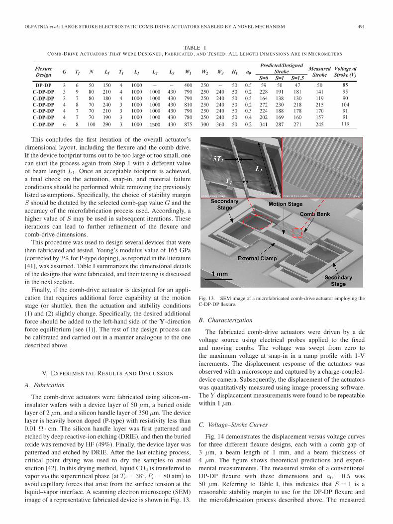
The comb-drive actuators were fabricated using silicon-on-insulator wafers with a device layer of 50 μm, a buried oxidelayer of 2 μm, and a silicon handle layer of 350 μm. The devicelayer is heavily boron doped (P-type) with resistivity less than0.01 Ω · cm. The silicon handle layer was first patterned andetched by deep reactive-ion etching (DRIE), and then the buriedoxide was removed by HF (49%). Finally, the device layer waspatterned and etched by DRIE. After the last etching process,critical point drying was used to dry the samples to avoidstiction [42]. In this drying method, liquid CO2 is transferred tovapor via the supercritical phase (at Tc = 38◦, Pc = 80 atm) toavoid capillary forces that arise from the surface tension at theliquid–vapor interface. A scanning electron microscope (SEM)image of a representative fabricated device is shown in Fig. 13.
Fig. 13. SEM image of a microfabricated comb-drive actuator employing theC-DP-DP flexure.
B. Characterization
The fabricated comb-drive actuators were driven by a dcvoltage source using electrical probes applied to the fixedand moving combs. The voltage was swept from zero tothe maximum voltage at snap-in in a ramp profile with 1-Vincrements. The displacement response of the actuators wasobserved with a microscope and captured by a charge-coupled-device camera. Subsequently, the displacement of the actuatorswas quantitatively measured using image-processing software.The Y displacement measurements were found to be repeatablewithin 1 μm.
C. Voltage–Stroke Curves
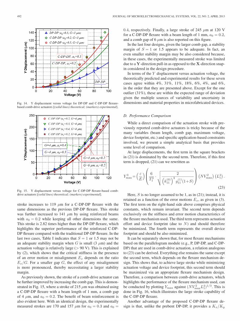
Fig. 14 demonstrates the displacement versus voltage curvesfor three different flexure designs, each with a comb gap of3 μm, a beam length of 1 mm, and a beam thickness of4 μm. The figure shows theoretical predictions and experi-mental measurements. The measured stroke of a conventionalDP-DP flexure with these dimensions and a0 = 0.5 was50 μm. Referring to Table I, this indicates that S = 1 is areasonable stability margin to use for the DP-DP flexure andthe microfabrication process described above. The measured
492 JOURNAL OF MICROELECTROMECHANICAL SYSTEMS, VOL. 22, NO. 2, APRIL 2013
Fig. 14. Y displacement versus voltage for DP-DP and C-DP-DP flexure-based comb-drive actuators [(solid lines) theoretical; (markers) experimental].
Fig. 15. Y displacement versus voltage for C-DP-DP flexure-based comb-drive actuators [(solid lines) theoretical; (markers) experimental].
stroke increases to 119 μm for a C-DP-DP flexure with thesame dimensions as the previous DP-DP flexure. This strokewas further increased to 141 μm by using reinforced beamswith a0 = 0.2 while keeping all other dimensions the same.This stroke is 2.82 times higher than the DP-DP flexure, whichhighlights the superior performance of the reinforced C-DP-DP flexure compared with the traditional DP-DP flexure. In thelast two cases, Table I indicates that S = 1 or 1.5 may not bean adequate stability margin when G is small (3 μm) and theactuation voltage is relatively large (> 90 V). This is explainedby (2), which shows that the critical stiffness in the presenceof an error motion or misalignment Ex depends on the ratioEx/G. For a smaller gap G, the effect of any misalignmentis more pronounced, thereby necessitating a larger stabilitymargin.
As previously shown, the stroke of a comb-drive actuator canbe further improved by increasing the comb gap. This is demon-strated in Fig. 15, where a stroke of 215 μm was obtained usinga C-DP-DP flexure with a beam length of 1 mm, a comb gapof 4 μm, and a0 = 0.2. The benefit of beam reinforcement isalso evident here. With an identical design, the experimentallymeasured strokes are 170 and 157 μm for a0 = 0.3 and a0 =
0.4, respectively. Finally, a large stroke of 245 μm at 120 Vfor a C-DP-DP flexure with a beam length of 1 mm, a0 = 0.2,and a comb gap of 6 μm is also reported on this figure.
In the last four designs, given the larger comb gap, a stabilitymargin of S = 1 or 1.5 appears to be adequate. In fact, aneven smaller stability margin may be also considered because,in these cases, the experimentally measured stroke was limiteddue to a Y-direction pull-in as opposed to the X-direction snap-in considered in the design procedure.
In terms of the Y displacement versus actuation voltage, thetheoretically predicted and experimental results for these sevencases agree within 4%, 31%, 11%, 18%, 6%, 4%, and 6%,in the order that they are presented above. Except for the oneoutlier (31%), these are within the expected range of deviationgiven the multiple sources of variability and uncertainty indimensions and material properties in microfabricated devices.
D. Performance Comparison
While a direct comparison of the actuation stroke with pre-viously reported comb-drive actuators is tricky because of themany variables (beam length, comb gap, maximum voltage,device footprint, etc.) and specific application-based constraintsinvolved, we present a simple analytical basis that providessome level of comparison.
At large displacements, the first term in the square bracketsin (21) is dominated by the second term. Therefore, if this firstterm is dropped, (21) can we rewritten as
Y 3max=
( ε
E
)⎛⎜⎝ 6
T 31
·√√√√ 2(
k(0)11
)3
g(1)11 (1+S)
⎞⎟⎠(
NV 2max
) (L41
).
(23)
Here, S is no longer assumed to be 1, as in (21); instead, it isretained as a function of the error motions Ex, as given in (3).The first term on the right-hand side above comprises physicalconstants, which remain invariant. The second term dependsexclusively on the stiffness and error motion characteristics ofthe flexure mechanism used. The third term represents actuationeffort and device footprint (due to N ) and should thereforebe minimized. The fourth term represents the overall devicefootprint and should be also minimized.
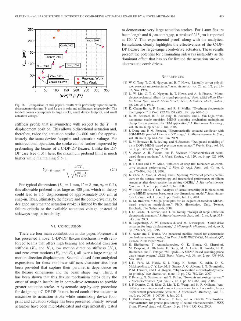
It can be separately shown that, for most flexure mechanismsbased on the parallelogram module (e.g., P, DP-DP, and C-DP-DP) that are used in comb-drive actuation, a relation analogousto (23) can be derived. Everything else remains the same exceptthe second term, which depends on the flexure mechanism de-sign. This shows that, to achieve large stroke while minimizingactuation voltage and device footprint, this second term shouldbe maximized via an appropriate flexure mechanism design.Therefore, a comparison between comb-drive actuators, whichhighlights the performance of the flexure mechanism used, canbe conducted by plotting Ymax against (NV 2
maxL41)
1/3. This isdone in Fig. 16, which illustrates the large stroke capability ofthe C-DP-DP flexure.
Another advantage of the proposed C-DP-DP flexure de-sign is that, unlike the prebent DP-DP, it provides a Kx/Ky
OLFATNIA et al.: LARGE STROKE ELECTROSTATIC COMB-DRIVE ACTUATORS ENABLED BY A NOVEL MECHANISM 493
Fig. 16. Comparison of this paper’s results with previously reported comb-drive actuator designs (V and L1 are in volts and millimeters, respectively.) Thetop-left corner corresponds to large stroke, small device footprint, and smallactuation voltage.
stiffness profile that is symmetric with respect to the Y = 0displacement position. This allows bidirectional actuation and,therefore, twice the actuation stroke (∼ 500 μm) for approx-imately the same device footprint and actuation voltage. Forunidirectional operation, the stroke can be further improved byprebending the beams of a C-DP-DP flexure. Unlike the DP-DP case [see (13)], here, the maximum prebend limit is muchhigher while maintaining S > 1
YP−B−max ≈√√√√ 4GL1√
k(0)11 g
(1)11
. (24)
For typical dimensions (L1 = 1 mm, G = 3 μm, a0 = 0.2),this allowable prebend is as large as 400 μm, which in theorycould lead to a Y displacement of approximately 500 μm atsnap-in. Thus, ultimately, the flexure and the comb drive may bedesigned such that the actuation stroke is limited by the materialfailure criteria or the available actuation voltage, instead ofsideways snap-in instability.
VI. CONCLUSION
There are four main contributions in this paper. Foremost, ithas presented a novel C-DP-DP flexure mechanism with rein-forced beams that offers high bearing and rotational directionstiffness (Kx and Kθ), low motion direction stiffness (Ky),and zero error motions (Ex and Eθ), all over a large range ofmotion direction displacement. Second, closed-form analyticalexpressions for these nonlinear stiffness characteristics havebeen provided that capture their parametric dependence onthe flexure dimensions and the beam shape (a0). Third, ithas been shown that this flexure mechanism helps delay theonset of snap-in instability in comb-drive actuators to providegreater actuation stroke. A systematic step-by-step procedurefor designing a C-DP-DP flexure-based comb-drive actuator tomaximize its actuation stroke while minimizing device foot-print and actuation voltage has been presented. Finally, severalactuators have been microfabricated and experimentally tested
to demonstrate very large actuation strokes. For 1-mm flexurebeam length and 6-μm comb gap, a stroke of 245 μm is reportedat 120 V. This experimental proof, along with the analyticalformulation, clearly highlights the effectiveness of the C-DP-DP flexure for large-range comb-drive actuators. These resultspresent the potential for eliminating sideways instability as thedominant effect that has so far limited the actuation stroke inelectrostatic comb drives.
REFERENCES
[1] W. C. Tang, T. C. H. Nguyen, and R. T. Howe, “Laterally driven polysil-icon resonant microstructures,” Sens. Actuators, vol. 20, no. 1/2, pp. 25–32, Nov. 1989.
[2] L. W. Lin, C. T. C. Nguyen, R. T. Howe, and A. P. Pisano, “Micro-electromechanical filters for signal-processing,” Proc. IEEE Micro Elec-tro Mech. Syst., Invest. Micro Struct., Sens., Actuators, Mach., Robot.,pp. 226–231, 1992.
[3] K. Chang-Jin, A. P. Pisano, and R. S. Muller, “Overhung electrostaticmicrogripper,” in Proc. TRANSDUCERS, 1991, pp. 610–613.
[4] D. M. Brouwer, B. R. de Jong, H. Soemers, and J. Van Dijk, “Sub-nanometer stable precision MEMS clamping mechanism maintainingclamp force unpowered for TEM application,” J. Micromech. Microeng.,vol. 16, no. 6, pp. S7–S12, Jun. 2006.
[5] J. Dong and P. M. Ferreira, “Electrostatically actuated cantilever withSOI-MEMS parallel kinematic XY stage,” J. Microelectromech. Syst.,vol. 18, no. 3, pp. 641–651, Jun. 2009.
[6] D. M. Brouwer, B. R. de Jong, and H. Soemers, “Design and modeling ofa six DOFs MEMS-based precision manipulator,” Precis. Eng., vol. 34,no. 2, pp. 307–319, Apr. 2010.
[7] S. Awtar, A. H. Slocum, and E. Sevincer, “Characteristics of beam-based flexure modules,” J. Mech. Design, vol. 129, no. 6, pp. 625–639,Jun. 2007.
[8] B. T. Chen and J. M. Miao, “Influence of deep RIE tolerances on comb-drive actuator performance,” J. Phys. D, Appl. Phys., vol. 40, no. 4,pp. 970–976, Feb. 21, 2007.
[9] K. Chen, A. Ayon, X. Zhang, and S. Spearing, “Effect of process param-eters on the surface morphology and mechanical performance of siliconstructures after deep reactive ion etching (DRIE),” J. Microelectromech.Syst., vol. 11, no. 3, pp. 264–275, Jun. 2002.
[10] W. Huang and G. Y. Lu, “Analysis of lateral instability of in-plane combdrive MEMS actuators based on a two-dimensional model,” Sens. Actua-tors A, Phys., vol. 113, no. 1, pp. 78–85, Jun. 15, 2004.
[11] D. M. Brouwer, “Design principles for six degrees-of-freedom MEMS-based precision manipulators,” Ph.D. dissertation, Univ. Twente,Enschede, The Netherlands, 2007.
[12] J. D. Grade, H. Jerman, and T. W. Kenny, “Design of large deflectionelectrostatic actuators,” J. Microelectromech. Syst., vol. 12, no. 3, pp. 335–343, Jun. 2003.
[13] R. Legtenberg, A. W. Groeneveld, and M. Elwenspoek, “Comb-driveactuators for large displacements,” J. Micromech. Microeng., vol. 6, no. 3,pp. 320–329, Sep. 1996.
[14] S. Awtar and T. Trutna, “An enhanced stability model for electrostaticcomb-drive actuator design,” in Proc. ASME IDETC/CIE, Montreal, QC,Canada, 2010, Paper 28943.
[15] E. Eleftheriou, T. Antonakopoulos, G. K. Binnig, G. Cherubini,M. Despont, A. Dholakia, U. Durig, M. A. Lantz, H. Pozidis, H. E.Rothuizen, and P. Vettiger, “Millipede—A MEMS-based scanning-probedata-storage system,” IEEE Trans. Magn., vol. 39, no. 2, pp. 938–945,Mar. 2003.
[16] J.-U. Park, M. Hardy, S. J. Kang, K. Barton, K. Adair, D. K.Mukhopadhyay, C. Y. Lee, M. S. Strano, A. G. Alleyne, J. G. Georgiadis,P. M. Ferreira, and J. A. Rogers, “High-resolution electrohydrodynamicjet printing,” Nat. Mater., vol. 6, no. 10, pp. 782–789, Oct. 2007.
[17] P. Beverly, G. Sivakumar, and T. Dallas, “Two-axis microstage system,”J. Microelectromech. Syst., vol. 17, no. 4, pp. 863–868, Aug. 2008.
[18] J. F. Domke, C. H. Rhee, Z. Liu, T. D. Wang, and K. R. Oldham, “Am-plifying transmission and compact suspension for a low-profile, large-displacement piezoelectric actuator,” J. Micromech. Microeng., vol. 21,no. 6, pp. 067004-1–067004-8, Jun. 2011.
[19] J. Muthuswamy, M. Okandan, T. Jain, and A. Gilletti, “Electrostaticmicroactuators for precise positioning of neural microelectrodes,” IEEETrans. Biomed. Eng., vol. 52, no. 10, pp. 1748–1755, Oct. 2005.
494 JOURNAL OF MICROELECTROMECHANICAL SYSTEMS, VOL. 22, NO. 2, APRIL 2013
[20] B. P. van Drieenhuizen, N. I. Maluf, I. E. Opris, and G. T. A.Kovacs, “Force-balanced accelerometer with mG resolution, fabricatedusing silicon fusion bonding and deep reactive ion etching,” in Proc.TRANSDUCERS, 1997, pp. 1229–1230.
[21] S. Awtar, K. Shimotsu, and S. Sen, “Elastic averaging in flexure mecha-nisms: A three-beam parallelogram flexure case study,” J. Mech. Robot.,vol. 2, no. 4, pp. 041006-1–041006-12, Nov. 2010.
[22] J. D. Grade and H. Jerman, “Electrostatic microactuator with offset and/orinclined comb drive fingers,” U.S. Patent 6 384 510, May 7, 2002.
[23] J. D. Grade, K. Y. Yasumura, and H. Jerman, “Advanced, vibration-resistant, comb-drive actuators for use in a tunable laser source,” Sens.Actuators A, Phys., vol. 114, no. 2/3, pp. 413–422, Sep. 2004.
[24] K. H. L. Chau, S. R. Lewis, Y. Zhao, R. T. Howe, S. F. Bart, and R. G.Marcheselli, “An integrated force-balanced capacitive accelerometer forlow-g applications,” Sens. Actuators A, Phys., vol. 54, no. 1–3, pp. 472–476, Jun. 1996.
[25] H. Jerman, J. D. Grade, and J. D. Drake, “Electrostatic microactuator andmethod for use thereof,” U.S. Patent 5 998 906, Dec. 7, 1999.
[26] G. Y. Zhou and P. Dowd, “Tilted folded-beam suspension for extendingthe stable travel range of comb-drive actuators,” J. Micromech. Microeng.,vol. 13, no. 2, pp. 178–183, Mar. 2003.
[27] R. V. Jones, Instruments and Experiences: Papers on Measurement andInstrument Design. New York: Wiley, 1988.
[28] D. M. Brouwer, A. Otten, J. B. C. Engelen, B. Krijnen, andH. M. J. R. Soemers, “Long-range elastic guidance mechanisms forelectrostatic comb-drive actuators,” in Proc. EUSPEN Int. Conf., Delft,The Netherlands, 2010, vol. 1, pp. 462–465.
[29] W. J. Ye, S. Mukherjee, and N. C. MacDonald, “Optimal shape de-sign of an electrostatic comb drive in microelectromechanical systems,”J. Microelectromech. Syst., vol. 7, no. 1, pp. 16–26, Mar. 1998.
[30] B. D. Jensen, S. Mutlu, S. Miller, K. Kurabayashi, and J. J. Allen, “Shapedcomb fingers for tailored electromechanical restoring force,” J. Microelec-tromech. Syst., vol. 12, no. 3, pp. 373–383, Jun. 2003.
[31] M. T. K. Hou, G. K. W. Huang, J. Y. Huang, K. M. Liao, R. S. Chen,and J. L. A. Yeh, “Extending displacements of comb drive actuators byadding secondary comb electrodes,” J. Micromech. Microeng., vol. 16,no. 4, pp. 684–691, Apr. 2006.
[32] J. C. Chiou, Y. J. Lin, and C. F. Kuo, “Extending the traveling range witha cascade electrostatic comb-drive actuator,” J. Micromech. Microeng.,vol. 18, no. 1, pp. 015018-1–015018-7, Jan. 2008.
[33] S. Kota, J. Hetrick, Z. Li, and L. Saggere, “Tailoring unconventional ac-tuators using compliant transmissions: Design methods and applications,”IEEE/ASME Trans. Mechatronics, vol. 4, no. 4, pp. 396–408, Dec. 1999.
[34] S. Kota, J. Joo, Z. Li, S. M. Rodgers, and J. Sniegowski, “Design of com-pliant mechanisms: Applications to MEMS,” J. Analog Integr. CircuitsSignal Process., vol. 29, no. 1/2, pp. 7–15, Nov. 2001.
[35] X. T. Huang, M. T. Saif, and N. C. MacDonald, “A micromotion ampli-fier,” in Proc. IEEE 9th Annu. Int. Workshop Micro Electro Mech. Syst.,Invest. Micro Struct., Sens., Actuators, Mach., Syst., 1996, pp. 424–428.
[36] Y. Nada, M. Medhat, M. Nagi, F. Marty, B. Saadany, and T. Bourouina,“Mechanical displacement multiplier: 250 μm stable travel range MEMSactuator using frictionless simple compliant structures,” in Proc. IEEE25th Int. Conf. MEMS, 2012, pp. 1161–1164.
[37] M. Olfatnia, S. Sood, and S. Awtar, “Large stroke electrostatic comb-driveactuators based on a novel flexure mechanism,” in Proc. Hilton HeadSolid-State Sens., Actuators, Microsyst. Workshop, 2012, pp. 409–412.
[38] S. Sood, Single-Axis Flexure Mechanisms Approaching Ideal BearingCharacteristics. Ann Arbor, MI: Univ. Michigan Press, 2012.
[39] J. L. A. Yeh, C. Y. Hui, and N. C. Tien, “Electrostatic model for anasymmetric combdrive,” J. Microelectromech. Syst., vol. 9, no. 1, pp. 126–135, Mar. 2000.
[40] D. Elata and V. Leus, “How slender can comb-drive fingers be?” J. Mi-cromech. Microeng., vol. 15, no. 5, pp. 1055–1059, May 2005.
[41] M. A. Hopcroft, W. D. Nix, and T. W. Kenny, “What is the Young’smodulus of silicon?” J. Microelectromech. Syst., vol. 19, no. 2, pp. 229–238, Apr. 2010.
[42] N. Tas, T. Sonnenberg, H. Jansen, R. Legtenberg, and M. Elwenspoek,“Stiction in surface micromachining,” J. Micromech. Microeng., vol. 6,no. 4, pp. 385–397, Dec. 1996.
Mohammad Olfatnia received the B.S. and M.S.degrees in applied mechanics from Isfahan Univer-sity of Technology, Isfahan, Iran, in 2005 and 2007,respectively, and the Ph.D. degree from NanyangTechnological University, Singapore, in 2011.
He is currently a Research Fellow with the Pre-cision Systems Design Laboratory, Department ofMechanical Engineering, University of Michigan,Ann Arbor. His research interests include the designand fabrication of MEMS-based sensors and actua-tors and mechatronics systems, and extending their
performance limits via model-based multidomain design.
Siddharth Sood received the B.Tech. degree in me-chanical engineering from the Indian Institute ofTechnology, Kanpur, India, in 2010. He is currentlyworking toward the M.S. degree in the PrecisionSystems Design Laboratory, University of Michigan,Ann Arbor. His Master’s thesis work is on develop-ing analysis and validation tools for flexure bearings.It also encompasses a holistic design procedure forcomb drive actuators employing flexure bearingsand metrics to compare the performance of differentflexure designs.
He is also currently with the Intelligent Systems Division, National In-stitute of Standards and Technology (NIST), Gaithersburg, MD, as a GuestResearcher. At NIST, he is currently working on developing a MEMS test bed tocharacterize the speed and resolution of atomic force microscopes and quantifythem for comparison across different instruments.
Jason J. Gorman (M’02) received the B.S. degreein aerospace engineering from Boston University,Boston, MA, in 1994 and the M.S. and Ph.D. degreesin mechanical engineering from The PennsylvaniaState University in 1999 and 2002, respectively.
In 2002, he joined the National Institute of Stan-dards and Technology (NIST), Gaithersburg, MD, asan NRC Postdoctoral Research Associate and hassince become a member of the technical staff withthe Intelligent Systems Division, where he leads theNEMS Measurement Science project. His research
interests include micro- and nanoelectromechanical systems, scanning probemicroscopy, nanomanufacturing, precision measurements, dynamic systems,and robust and nonlinear control.
Shorya Awtar received the B.Tech. degree fromthe Indian Institute of Technology Kanpur, Kanpur,India, in 1998, the M.S. degree from RensselaerPolytechnic Institute, Troy, NY, in 2000, and theSc.D. degree from Massachusetts Institute of Tech-nology, Cambridge, in 2003, all in mechanicalengineering.
Prior to joining the University of Michigan, AnnArbor, he worked at the General Electric CompanyGlobal Research Center until 2006. He is currentlyan Assistant Professor of Mechanical Engineering
and the Director of the Precision Systems Design Laboratory at the Uni-versity of Michigan. His engineering and research interests include machinedesign, flexure mechanisms, precision engineering, and mechatronic systems.The current focus of his research group is on precision motion systems fornanometrology and nanomanufacturing, minimally invasive surgical tools, andmicroscale motion stages.
Dr. Awtar is a member of the American Society of Mechanical Engineers(ASME). He was a recipient of the National Science Foundation CAREERAward in 2009 and the ASME Leonardo da Vinci Award in 2011.

![Chip-Based Lithium-Niobate Frequency Combs...comb generator [Fig. 1(a)] [12]. An electrically programmable add-drop filter is monolithically integrated to arbitrarily pick out one](https://static.fdocument.org/doc/165x107/611ad94f0b31f66c21696eb0/chip-based-lithium-niobate-frequency-combs-comb-generator-fig-1a-12.jpg)