Hydraulic Circuits. Introduction A hydraulic circuit is a group of components including one or more...
57
Hydraulic Circuits
-
Upload
lambert-benson -
Category
Documents
-
view
227 -
download
6
Transcript of Hydraulic Circuits. Introduction A hydraulic circuit is a group of components including one or more...
Hydraulic Circuits
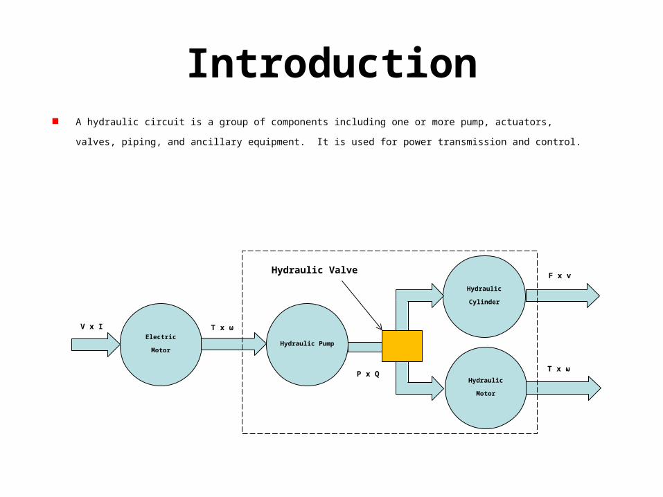
Introduction A hydraulic circuit is a group of components including one or more pump, actuators, valves, piping, and ancillary equipment. It is
used for power transmission and control.
Hydraulic Cylinder
Electric Motor
T x ωV x I
Hydraulic Pump
P x Q
Hydraulic Motor
F x v
T x ω
Hydraulic Valve
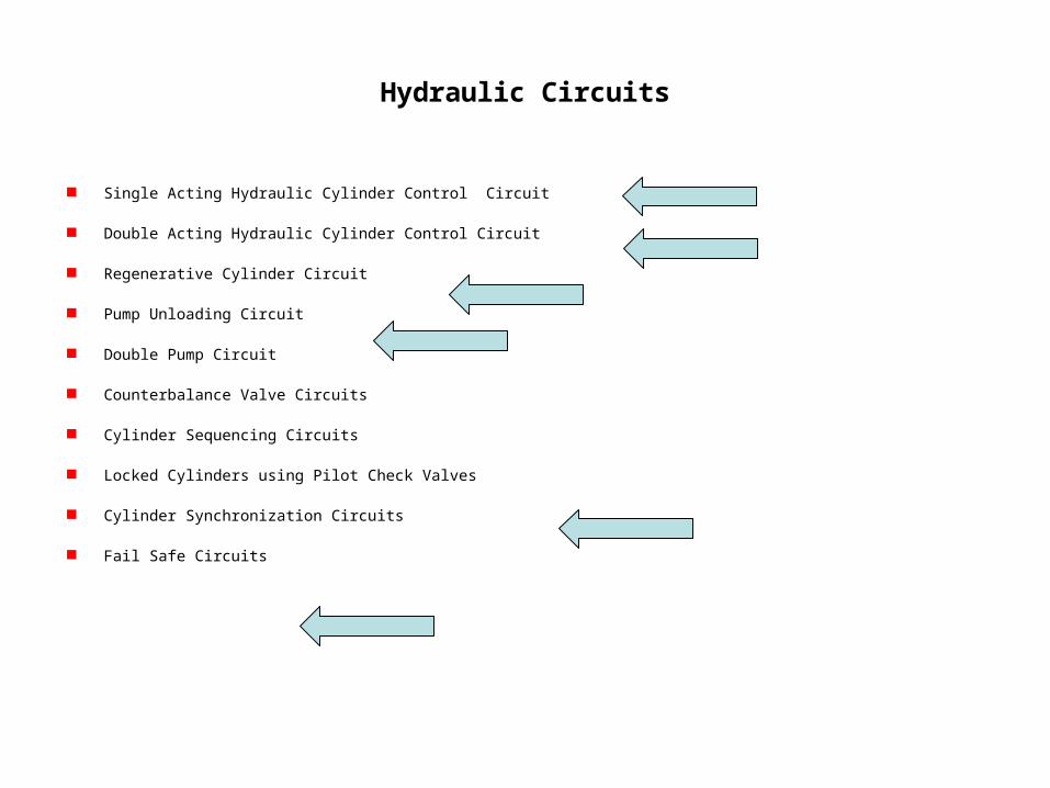
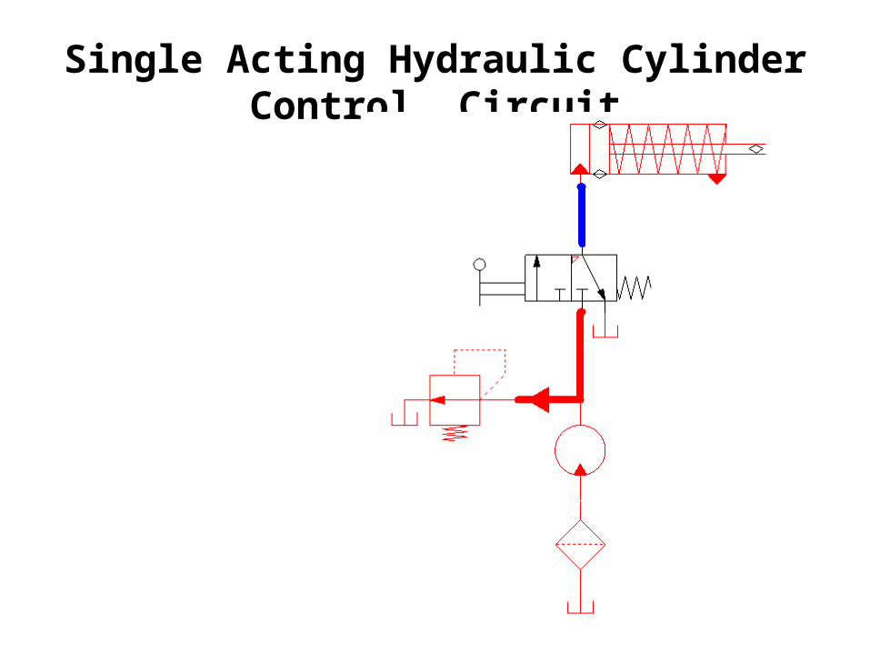
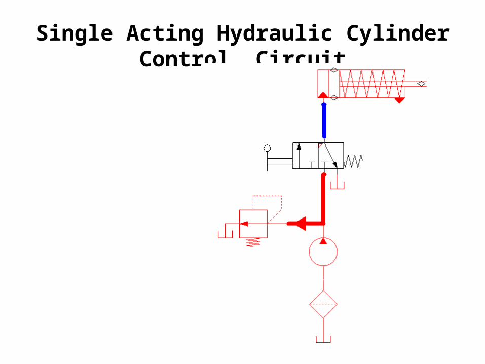
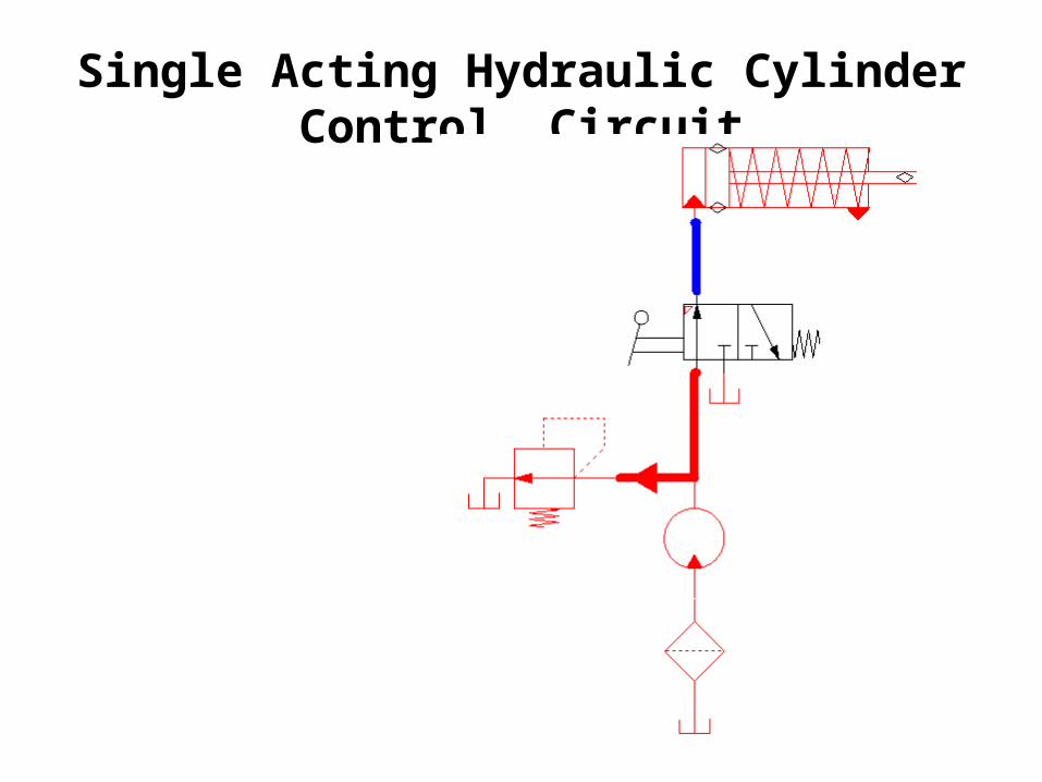
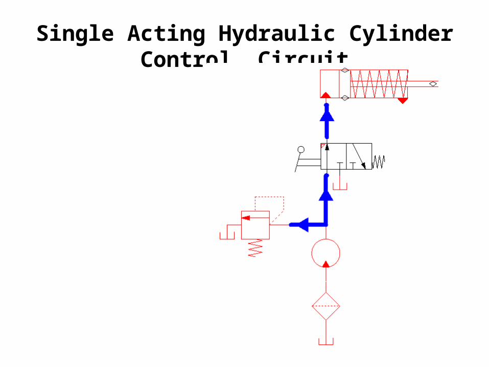
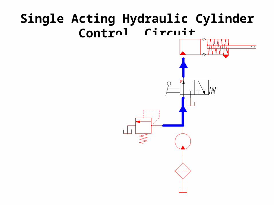
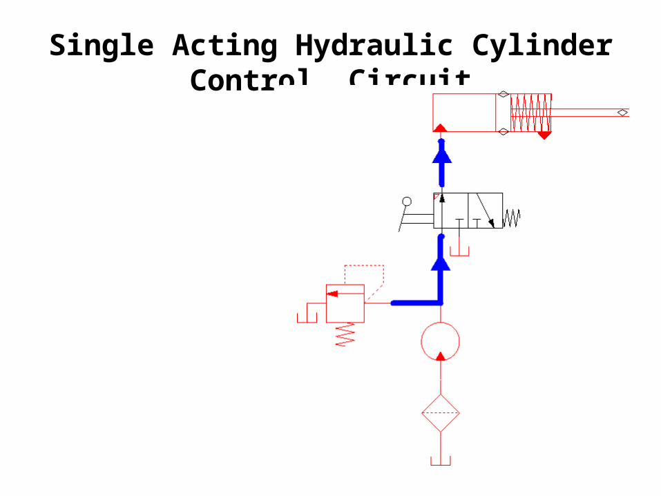
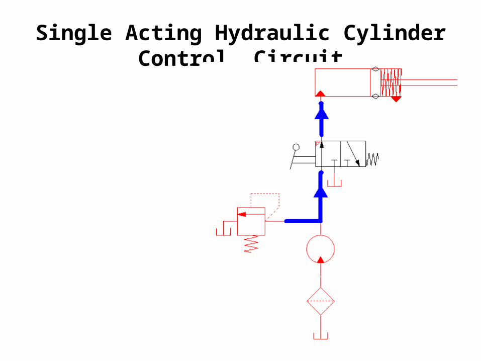
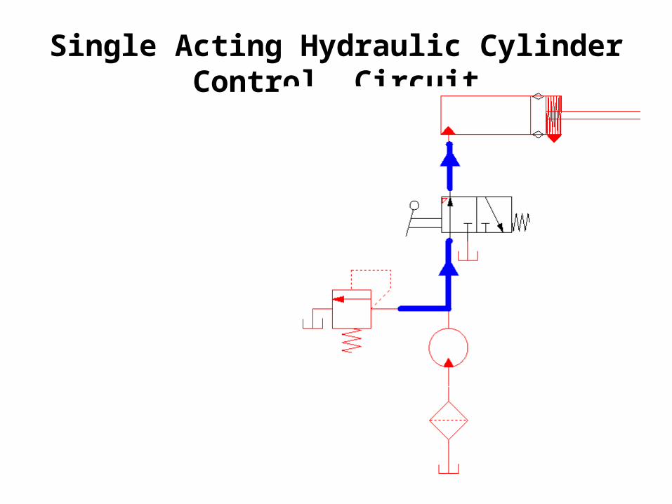
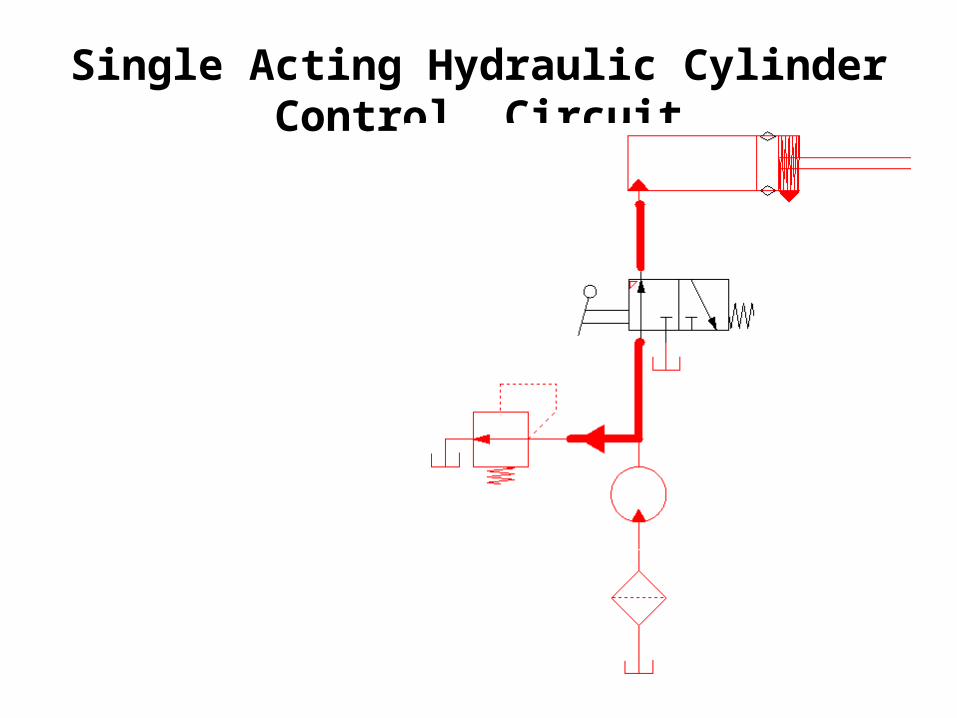
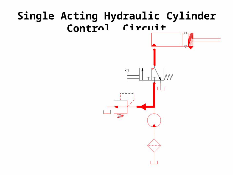
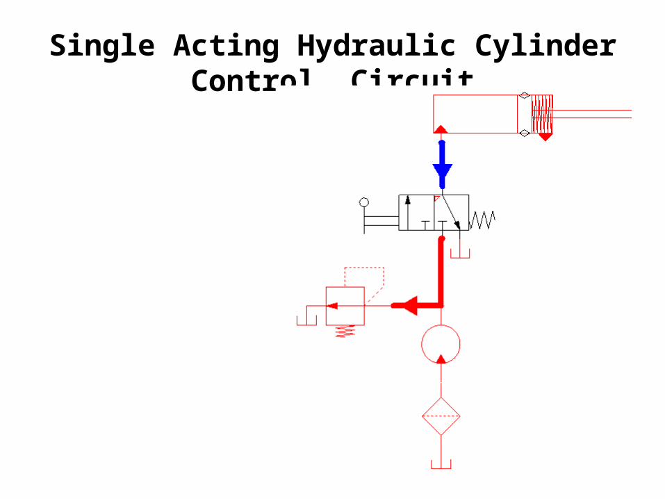
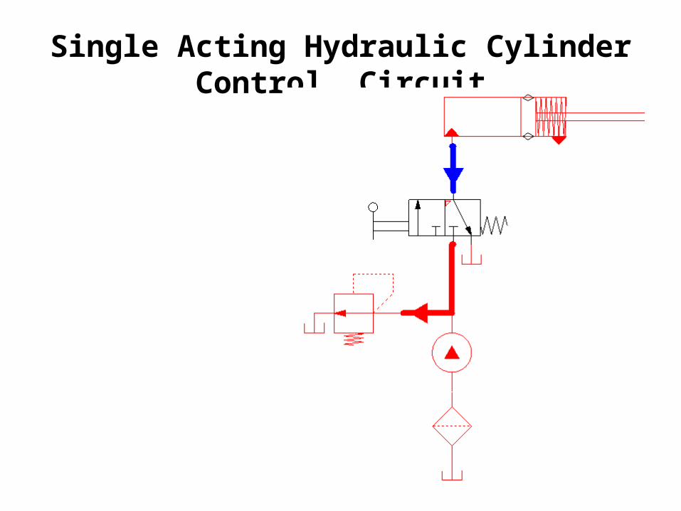
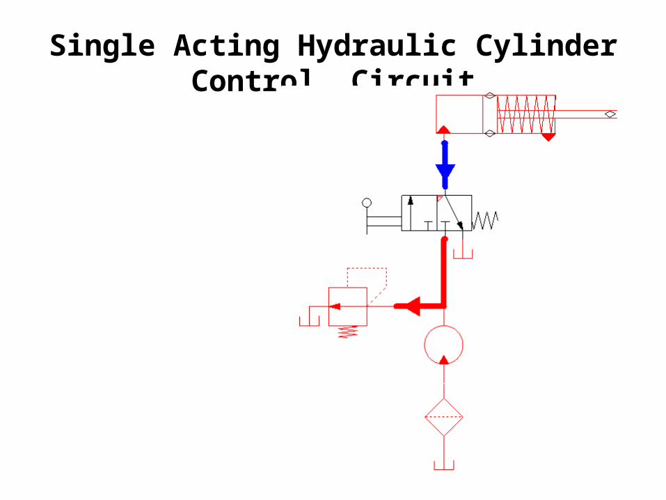
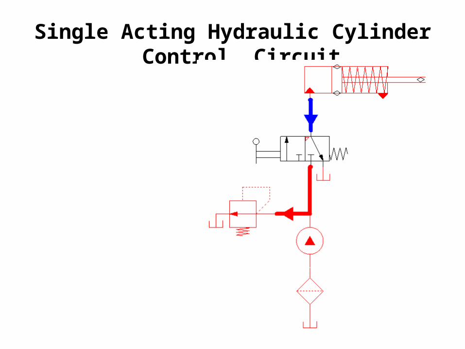
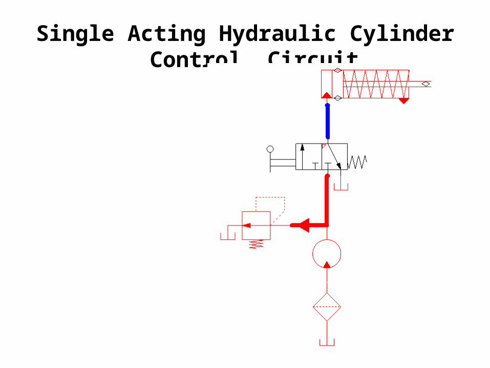
Single Acting Hydraulic Cylinder Control Circuit
Double Acting Hydraulic Cylinder Control Circuit
Regenerative Cylinder Circuit
Pump Unloading Circuit
Double Pump Circuit
Counterbalance Valve Circuits
Cylinder Sequencing Circuits
Locked Cylinders using Pilot Check Valves
Cylinder Synchronization Circuits
Fail Safe Circuits
Hydraulic Circuits

Single Acting Hydraulic Cylinder Control Circuit

Single Acting Hydraulic Cylinder Control Circuit
Single Acting Hydraulic Cylinder Control Circuit
Single Acting Hydraulic Cylinder Control Circuit
Single Acting Hydraulic Cylinder Control Circuit
Single Acting Hydraulic Cylinder Control Circuit

Single Acting Hydraulic Cylinder Control Circuit
Single Acting Hydraulic Cylinder Control Circuit
Single Acting Hydraulic Cylinder Control Circuit
Single Acting Hydraulic Cylinder Control Circuit
Single Acting Hydraulic Cylinder Control Circuit

Single Acting Hydraulic Cylinder Control Circuit
Single Acting Hydraulic Cylinder Control Circuit
Single Acting Hydraulic Cylinder Control Circuit
Single Acting Hydraulic Cylinder Control Circuit
Single Acting Hydraulic Cylinder Control Circuit

Single Acting Hydraulic Cylinder Control Circuit
Single Acting Hydraulic Cylinder Control Circuit
Single Acting Hydraulic Cylinder Control Circuit
Single Acting Hydraulic Cylinder Control Circuit
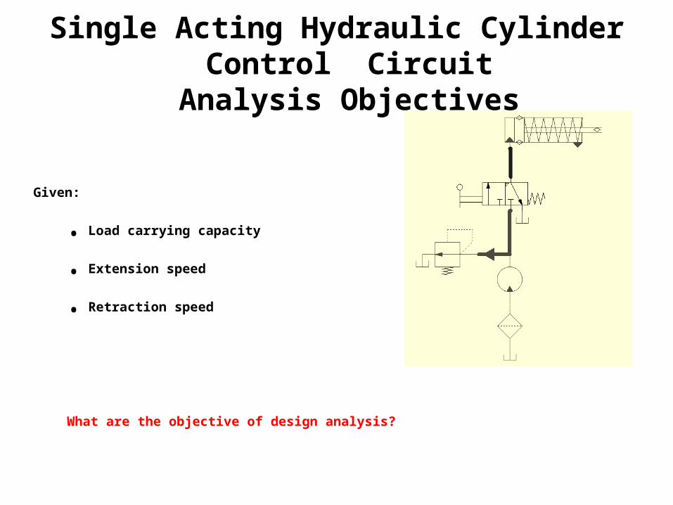
Single Acting Hydraulic Cylinder Control CircuitAnalysis Objectives
Given:
• Load carrying capacity
• Extension speed
• Retraction speed
What are the objective of design analysis?
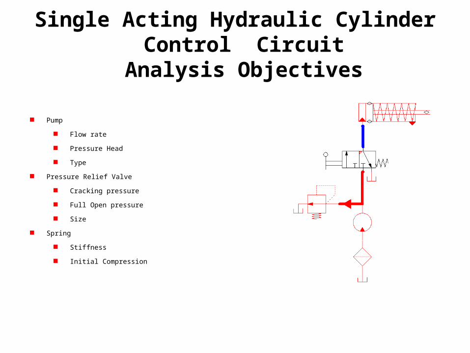
Single Acting Hydraulic Cylinder Control CircuitAnalysis Objectives
Pump
Flow rate
Pressure Head
Type
Pressure Relief Valve
Cracking pressure
Full Open pressure
Size
Spring
Stiffness
Initial Compression
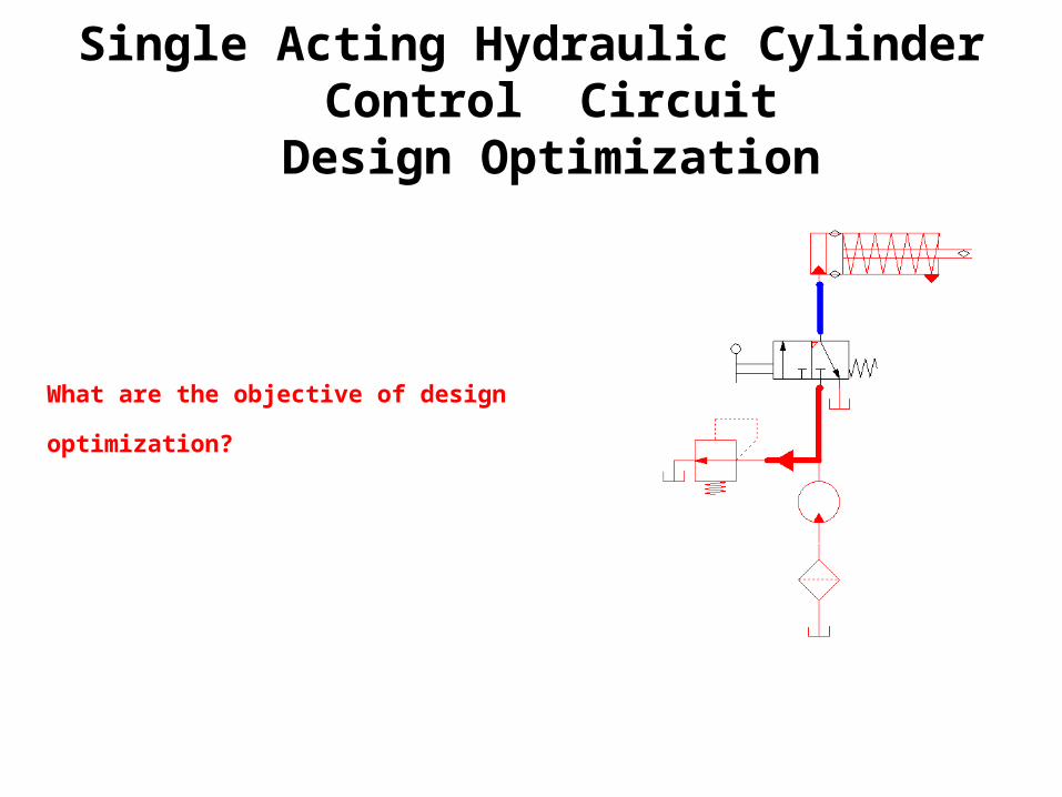
Single Acting Hydraulic Cylinder Control CircuitDesign Optimization
What are the objective of design optimization?
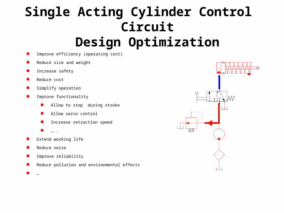
Single Acting Cylinder Control CircuitDesign Optimization
Improve efficiency (operating cost)
Reduce size and weight
Increase safety
Reduce cost
Simplify operation
Improve functionality
Allow to stop during stroke
Allow servo control
Increase retraction speed
…..
Extend working life
Reduce noise
Improve reliability
Reduce pollution and environmental effects
…
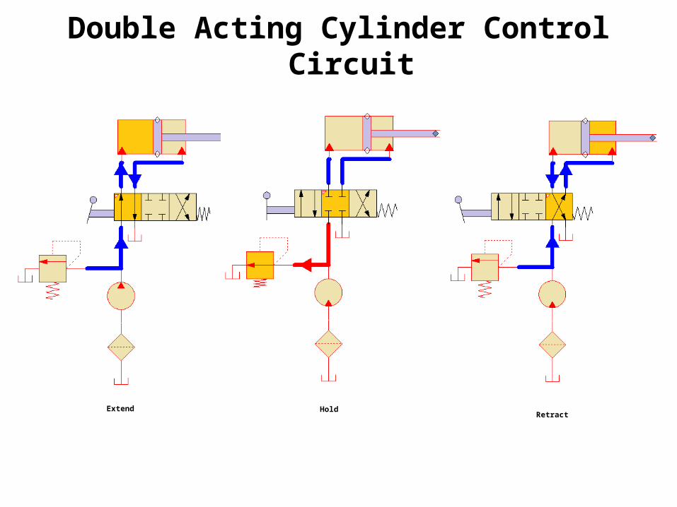
Double Acting Cylinder Control Circuit
Extend HoldRetract
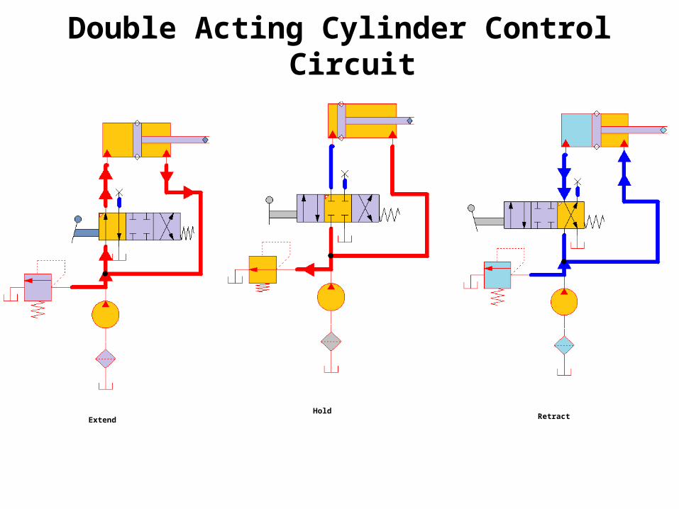
Double Acting Cylinder Control Circuit
ExtendHold
Retract
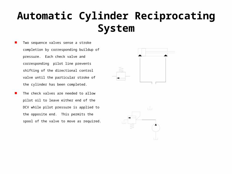
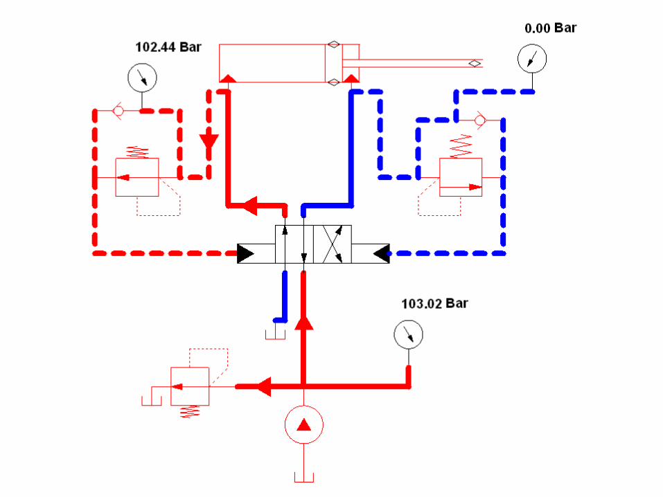
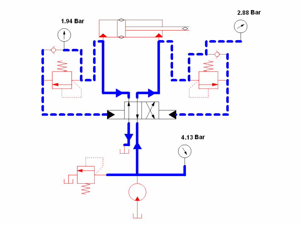
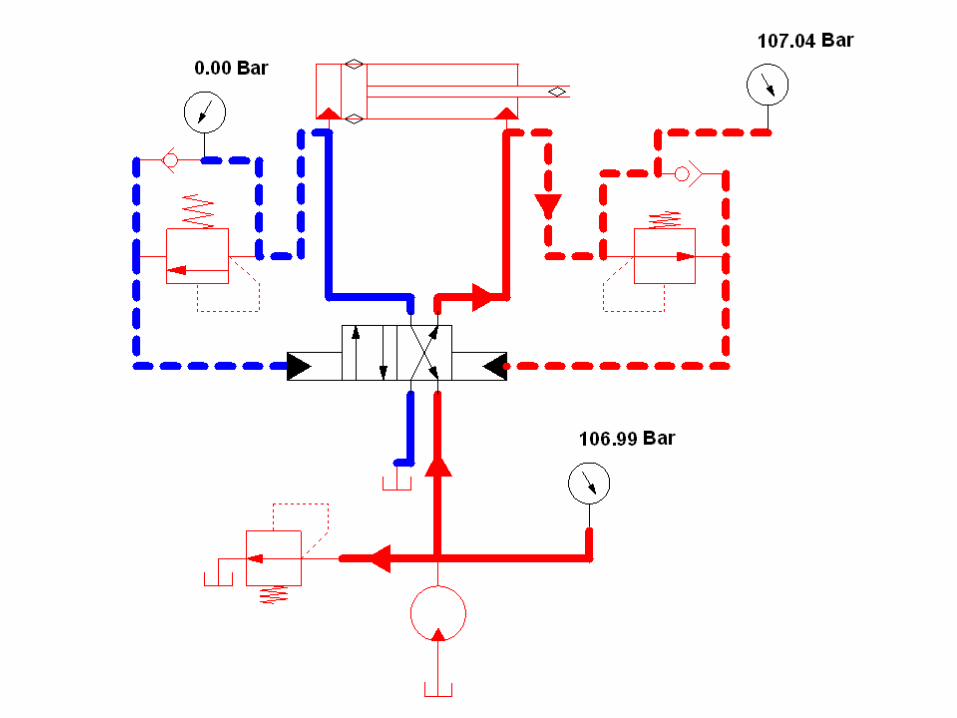
Automatic Cylinder Reciprocating System
Two sequence valves sense a stroke completion by
corresponding buildup of pressure. Each check valve and
corresponding pilot line prevents shifting of the
directional control valve until the particular stroke of the
cylinder has been completed.
The check valves are needed to allow pilot oil to leave
either end of the DCV while pilot pressure is applied to
the opposite end. This permits the spool of the valve to
move as required.0.00 Bar
0.00 Bar
0.00 Bar
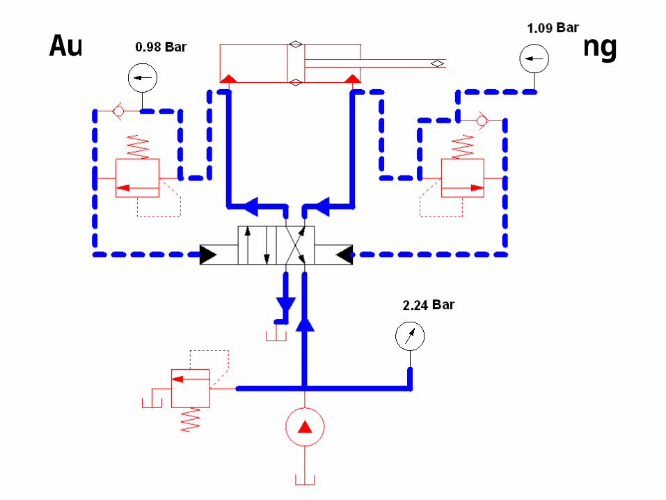
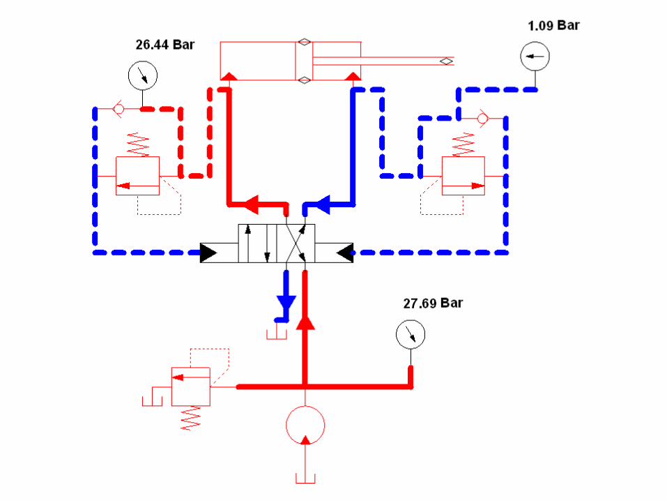
Automatic cylinder Reciprocating System

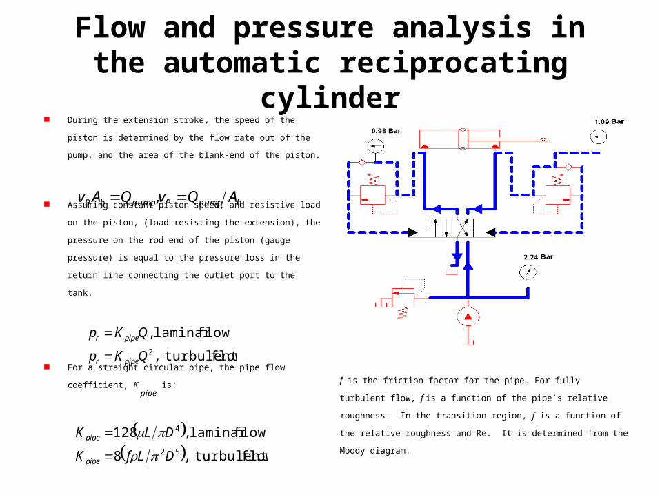
During the extension stroke, the speed of the piston is determined by the
flow rate out of the pump, and the area of the blank-end of the piston.
Assuming constant piston speed, and resistive load on the piston, (load
resisting the extension), the pressure on the rod end of the piston (gauge
pressure) is equal to the pressure loss in the return line connecting the
outlet port to the tank.
For a straight circular pipe, the pipe flow coefficient, K pipe
is:
bpumpPpumpbP AQvQAv ,
flow turbulent,
flowlaminar ,2QKp
QKp
piper
piper
Flow and pressure analysis in the automatic reciprocating cylinder
flow turbulent,8
flowlaminar ,12852
4
DLfK
DLK
pipe
pipe
f is the friction factor for the pipe. For fully turbulent flow, f is a function of the
pipe’s relative roughness. In the transition region, f is a function of the relative
roughness and Re. It is determined from the Moody diagram.
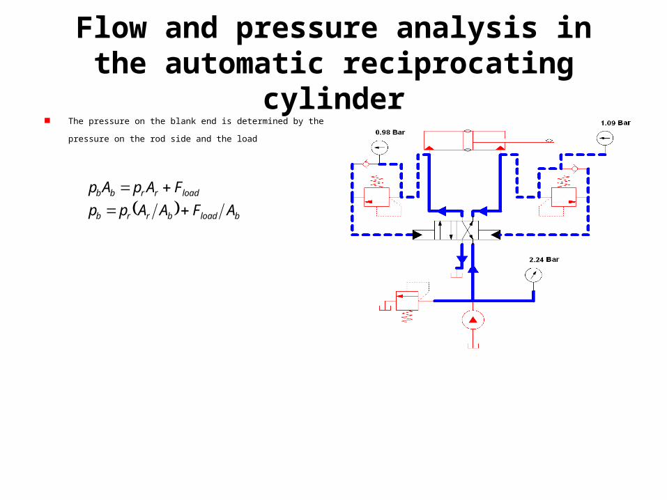
The pressure on the blank end is determined by the pressure on the rod
side and the load
bloadbrrb
loadrrbb
AFAApp
FApAp
Flow and pressure analysis in the automatic reciprocating cylinder
Double Pump Hydraulic System
Double Pump Hydraulic System
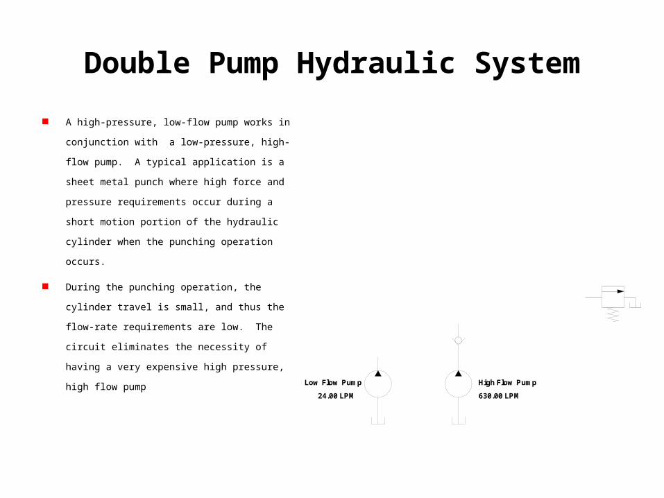
A high-pressure, low-flow pump works in conjunction
with a low-pressure, high-flow pump. A typical
application is a sheet metal punch where high force and
pressure requirements occur during a short motion
portion of the hydraulic cylinder when the punching
operation occurs.
During the punching operation, the cylinder travel is
small, and thus the flow-rate requirements are low. The
circuit eliminates the necessity of having a very
expensive high pressure, high flow pump
24.00 LPM
Low Flow Pump
630.00 LPM
High Flow Pump
0.00 Bar
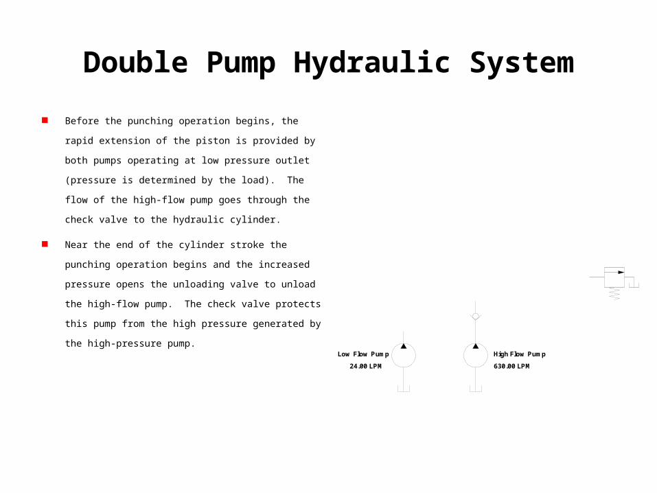
Double Pump Hydraulic System
Before the punching operation begins, the rapid extension of the
piston is provided by both pumps operating at low pressure outlet
(pressure is determined by the load). The flow of the high-flow
pump goes through the check valve to the hydraulic cylinder.
Near the end of the cylinder stroke the punching operation begins
and the increased pressure opens the unloading valve to unload
the high-flow pump. The check valve protects this pump from the
high pressure generated by the high-pressure pump.
24.00 LPM
Low Flow Pump
630.00 LPM
High Flow Pump
0.00 Bar
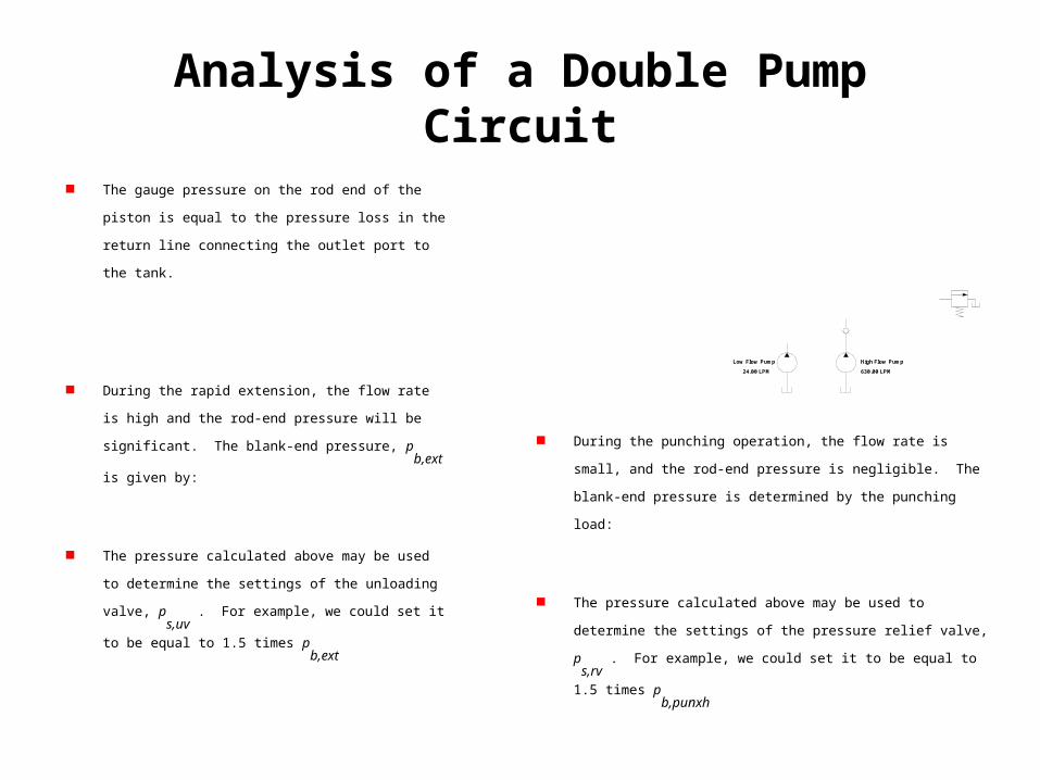
During the punching operation, the flow rate is small, and the rod-end
pressure is negligible. The blank-end pressure is determined by the punching
load:
The pressure calculated above may be used to determine the settings of the
pressure relief valve, ps,rv
. For example, we could set it to be equal to 1.5
times pb,punxh
Analysis of a Double Pump Circuit
The gauge pressure on the rod end of the piston is equal to the
pressure loss in the return line connecting the outlet port to the
tank.
During the rapid extension, the flow rate is high and the rod-end
pressure will be significant. The blank-end pressure, pb,ext
is
given by:
The pressure calculated above may be used to determine the
settings of the unloading valve, ps,uv
. For example, we could
set it to be equal to 1.5 times pb,ext
24.00 LPM
Low Flow Pump
630.00 LPM
High Flow Pump
0.00 Bar
flow turbulent,
flowlaminar ,2
,
,
QKp
QKp
pipeextr
pipeextr
brextrextb AApp ,,
bloadbrrb
loadrrbb
AFAApp
FApAp
bpunchpunchb AFp ,
Fail-Safe Circuits
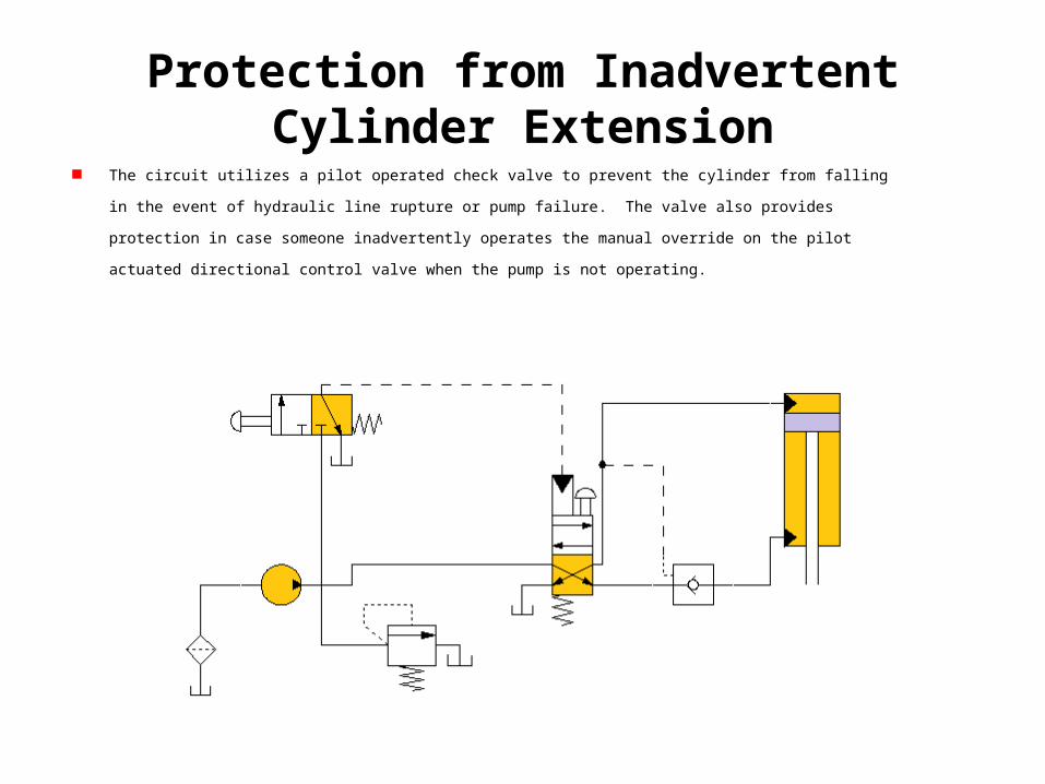
Protection from Inadvertent Cylinder Extension The circuit utilizes a pilot operated check valve to prevent the cylinder from falling in the event of hydraulic line rupture or pump
failure. The valve also provides protection in case someone inadvertently operates the manual override on the pilot actuated
directional control valve when the pump is not operating.

Protection from Inadvertent Cylinder Extension This design also allows the upper directional control valve to be placed at a distant location from the machine. The lines
connected to the valve are basically for sensing. Flow and pressure (high power lines) go though the bottom DCV, which acts in
a manner similar to relay.
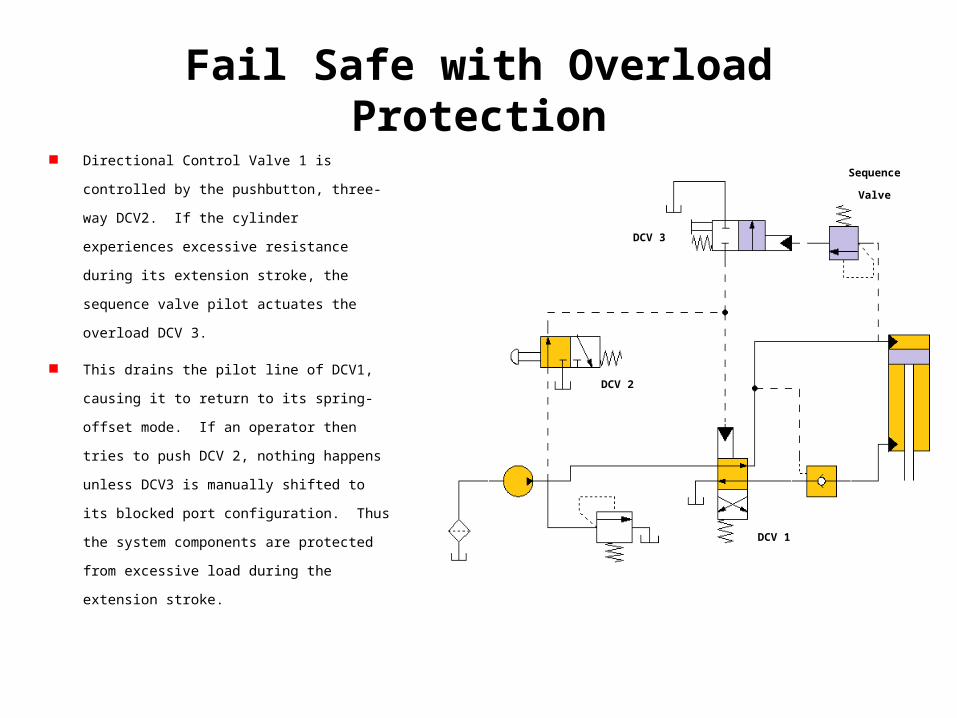
Fail Safe with Overload Protection Directional Control Valve 1 is controlled by the
pushbutton, three-way DCV2. If the cylinder
experiences excessive resistance during its extension
stroke, the sequence valve pilot actuates the overload
DCV 3.
This drains the pilot line of DCV1, causing it to return
to its spring-offset mode. If an operator then tries to
push DCV 2, nothing happens unless DCV3 is manually
shifted to its blocked port configuration. Thus the
system components are protected from excessive load
during the extension stroke.
DCV 1
DCV 2
Sequence Valve
DCV 3
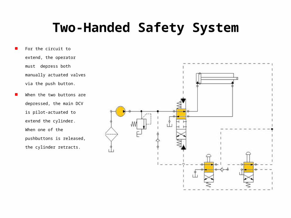
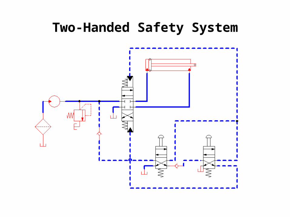
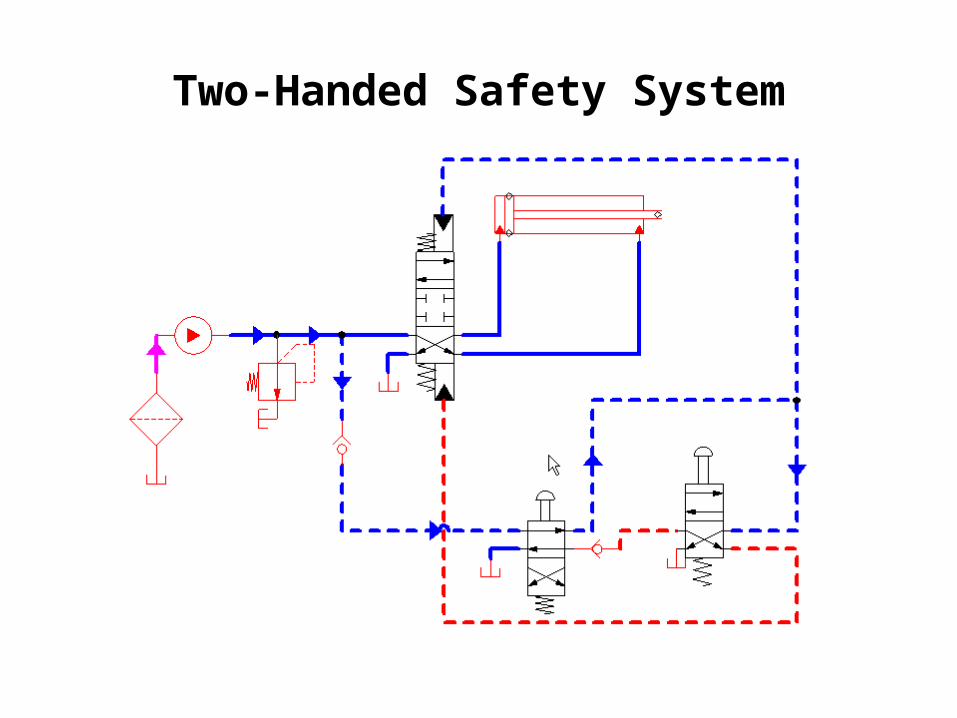
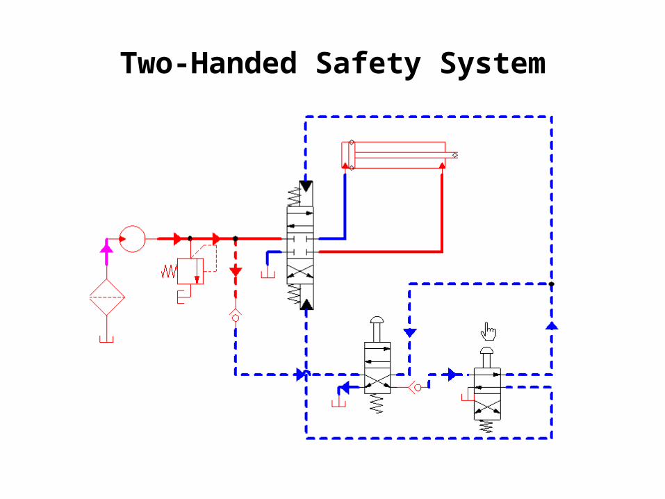
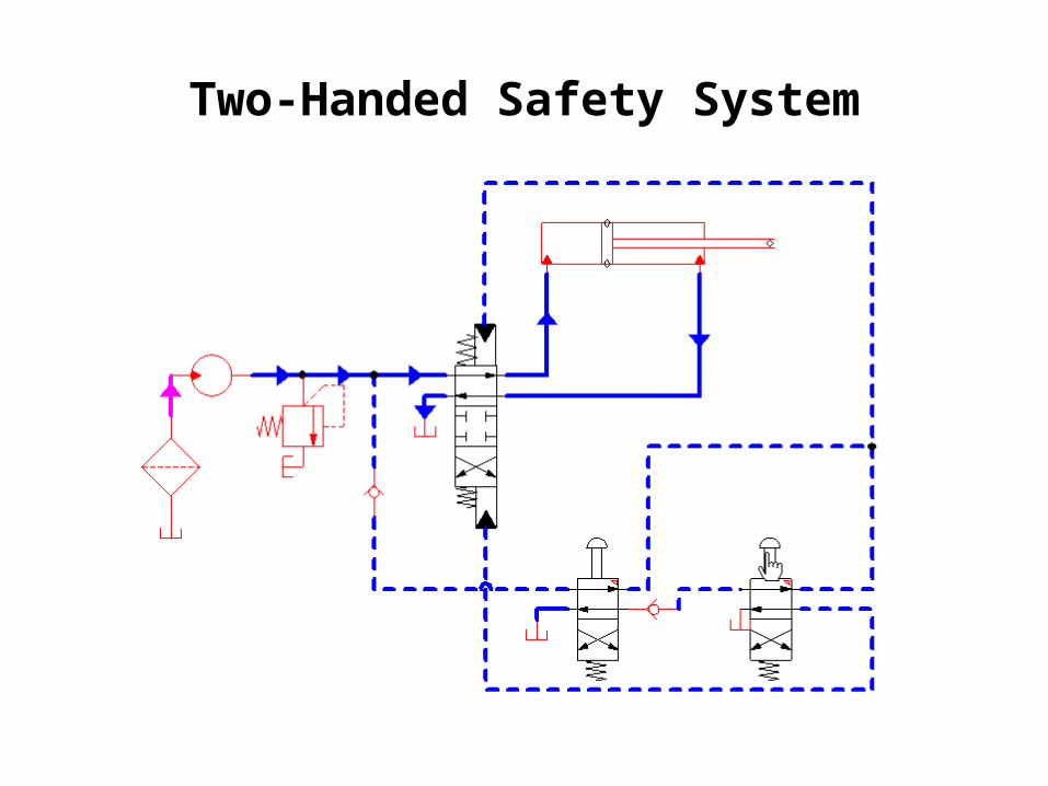
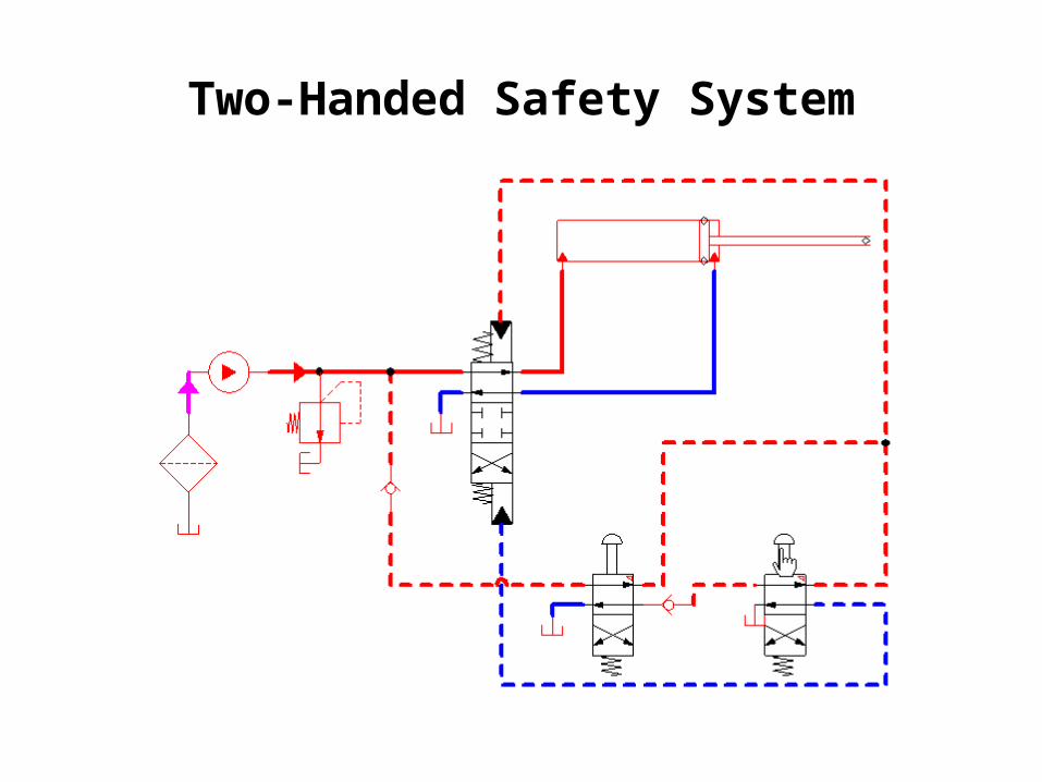
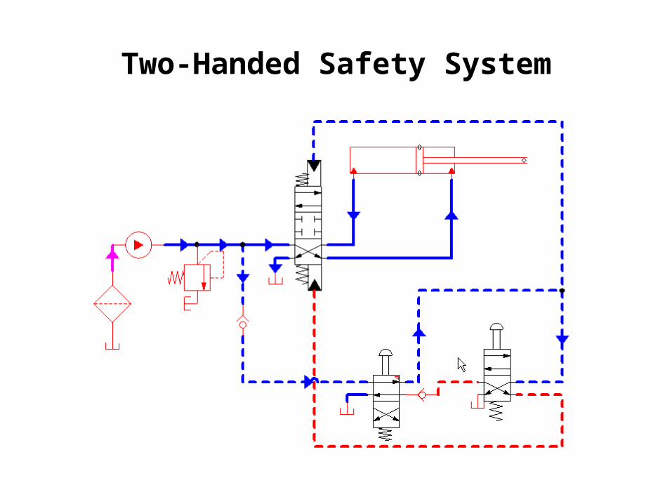
Two-Handed Safety System For the circuit to extend, the
operator must depress both
manually actuated valves via the
push button.
When the two buttons are
depressed, the main DCV is pilot-
actuated to extend the cylinder.
When one of the pushbuttons is
released, the cylinder retracts.
Two-Handed Safety System
Two-Handed Safety System
Two-Handed Safety System

Two-Handed Safety System
Two-Handed Safety System
Two-Handed Safety System
Two-Handed Safety System