Hydraulic Motors Series V12, V14, T12 - H & P...
68
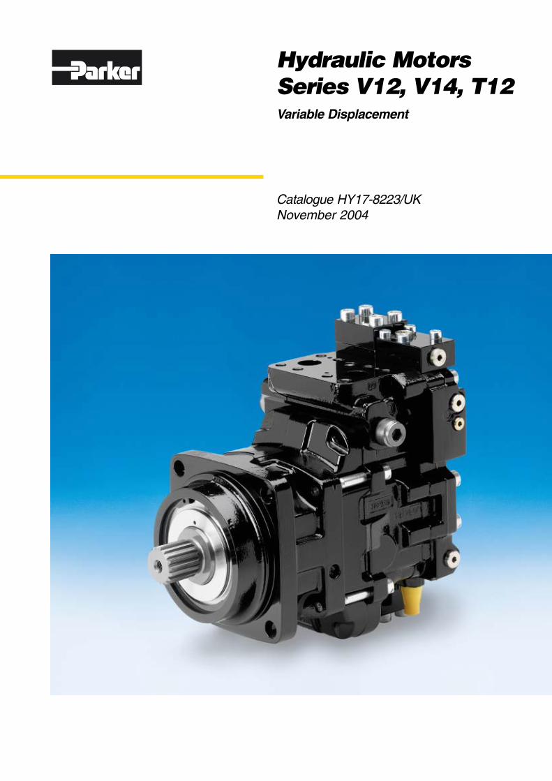
Catalogue HY17-8223/UK November 2004 Hydraulic Motors Series V12, V14, T12 Variable Displacement
Transcript of Hydraulic Motors Series V12, V14, T12 - H & P...
Catalogue HY17-8223/UKNovember 2004
Hydraulic MotorsSeries V12, V14, T12Variable Displacement
2 Parker HannifinMobile Controls DivisionTrollhättan, Sweden
Hydraulic MotorsSeries V12, V14 and T12
Catalogue HY17-8223/UK
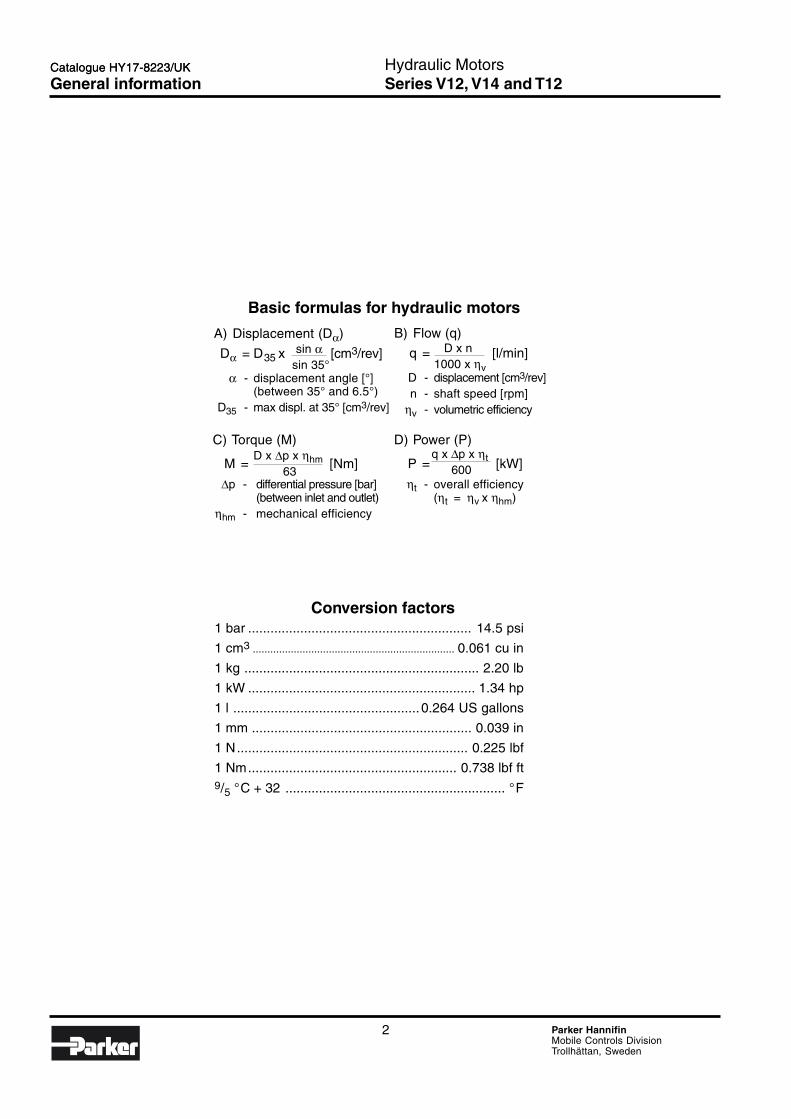
C) Torque (M)
M = [Nm]
∆p - differential pressure [bar](between inlet and outlet)
ηhm - mechanical efficiency
Conversion factors1 bar ............................................................ 14.5 psi
1 cm3 ..................................................................... 0.061 cu in
1 kg ............................................................... 2.20 lb
1 kW ............................................................. 1.34 hp
1 l .................................................. 0.264 US gallons
1 mm ........................................................... 0.039 in
1 N.............................................................. 0.225 lbf
1 Nm........................................................ 0.738 lbf ft9/5 °C + 32 ........................................................... °F
Basic formulas for hydraulic motors
B) Flow (q)
q = [l/min]
D - displacement [cm3/rev]n - shaft speed [rpm]
ηv - volumetric efficiency
A) Displacement (Dα)
Dα = D35 x [cm3/rev]
α - displacement angle [°](between 35° and 6.5°)
D35 - max displ. at 35° [cm3/rev]
D) Power (P)
P = [kW]
ηt - overall efficiency(ηt = ηv x ηhm)
D x n 1000 x ηv
sin α sin 35°
D x ∆p x ηhm 63
q x ∆p x ηt 600
Catalogue HY17-8223/UK
General information
3 Parker HannifinMobile Controls DivisionTrollhättan, Sweden
Hydraulic MotorsSeries V12, V14 and T12
Catalogue HY17-8223/UK
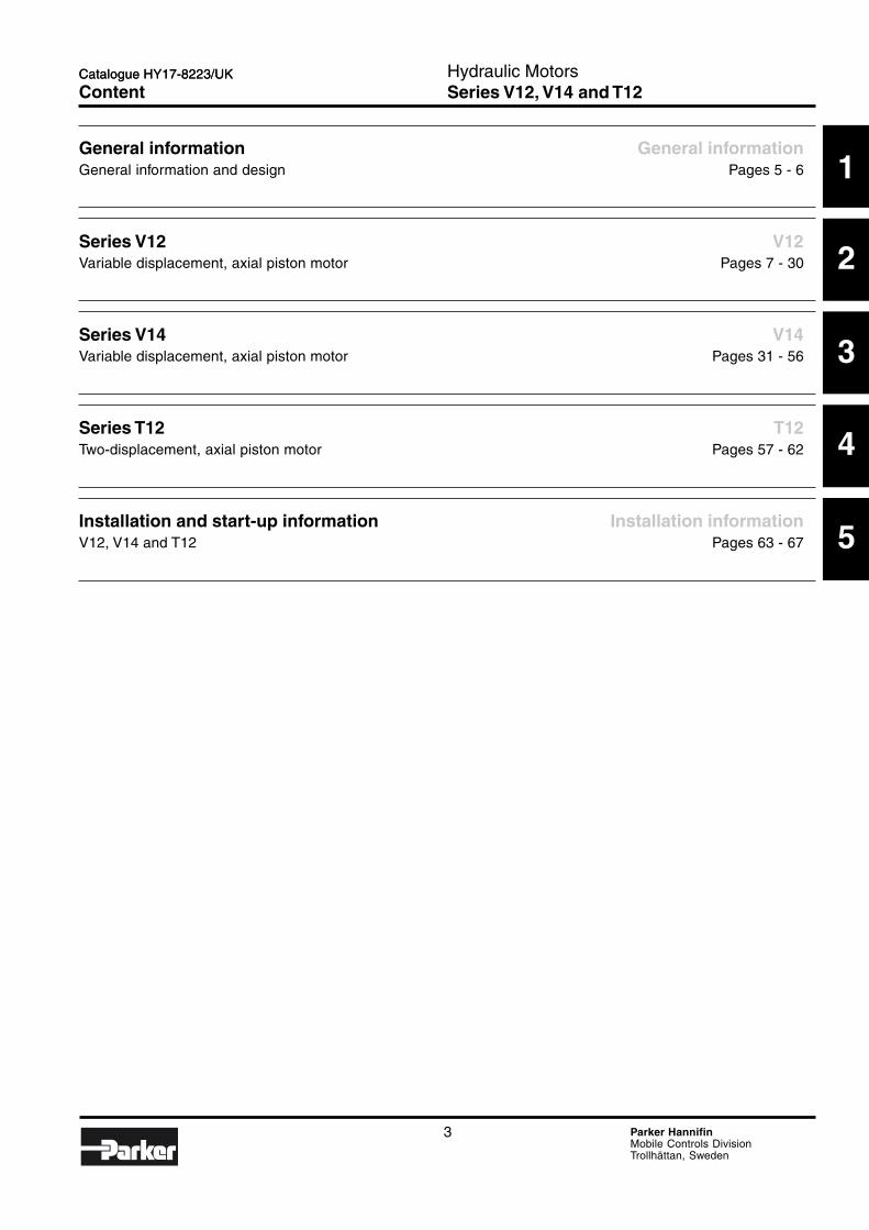
.............................................................................................................................................................................. 3
General information ......................................................................................................................... 5General information and design ........................................................................................................................................ 5
Serie V12 ........................................................................................................................................... 7Content ............................................................................................................................................................................. 7
Serie V14 ......................................................................................................................................... 31Content ........................................................................................................................................................................... 31
Serie T12 .......................................................................................................................................... 57Content ........................................................................................................................................................................... 57
Installation and start-up information ............................................................................................ 63Content ........................................................................................................................................................................... 63
Catalogue HY17-8223/UK
Content
1
2
3
4
5
General information General informationGeneral information and design Pages 5 - 6
Series V12 V12Variable displacement, axial piston motor Pages 7 - 30
Series V14 V14Variable displacement, axial piston motor Pages 31 - 56
Series T12 T12Two-displacement, axial piston motor Pages 57 - 62
Installation and start-up information Installation informationV12, V14 and T12 Pages 63 - 67
4 Parker HannifinMobile Controls DivisionTrollhättan, Sweden
Hydraulic MotorsSeries V12, V14 and T12
Catalogue HY17-8223/UKCatalogue HY17-8223/UK
Notes
5 Parker HannifinMobile Controls DivisionTrollhättan, Sweden
Hydraulic MotorsSeries V12, V14 and T12
Catalogue HY17-8223/UK
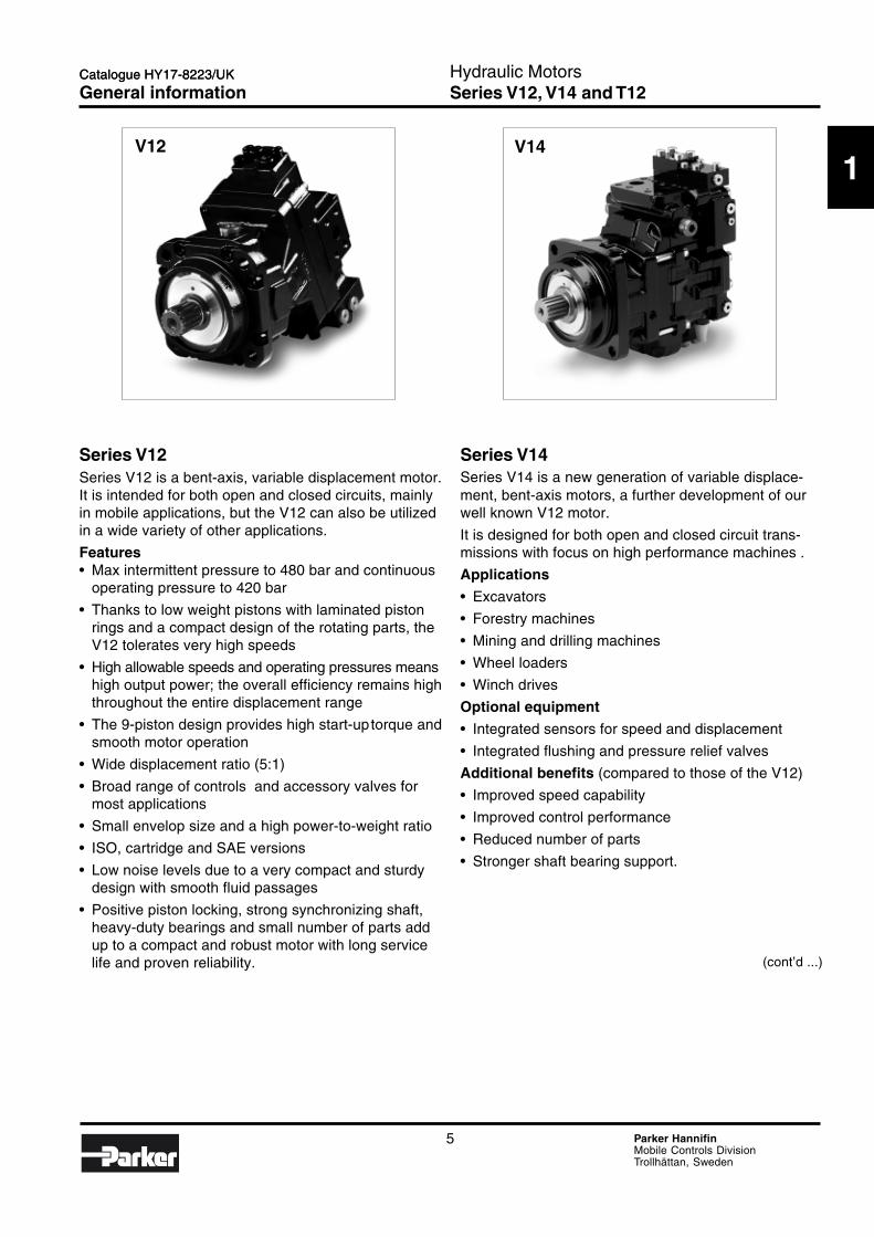
Series V12Series V12 is a bent-axis, variable displacement motor.It is intended for both open and closed circuits, mainlyin mobile applications, but the V12 can also be utilizedin a wide variety of other applications.
Features• Max intermittent pressure to 480 bar and continuous
operating pressure to 420 bar
• Thanks to low weight pistons with laminated pistonrings and a compact design of the rotating parts, theV12 tolerates very high speeds
• High allowable speeds and operating pressures meanshigh output power; the overall efficiency remains highthroughout the entire displacement range
• The 9-piston design provides high start-uptorque andsmooth motor operation
• Wide displacement ratio (5:1)
• Broad range of controls and accessory valves formost applications
• Small envelop size and a high power-to-weight ratio
• ISO, cartridge and SAE versions
• Low noise levels due to a very compact and sturdydesign with smooth fluid passages
• Positive piston locking, strong synchronizing shaft,heavy-duty bearings and small number of parts addup to a compact and robust motor with long servicelife and proven reliability.
Series V14Series V14 is a new generation of variable displace-ment, bent-axis motors, a further development of ourwell known V12 motor.
It is designed for both open and closed circuit trans-missions with focus on high performance machines .
Applications
• Excavators
• Forestry machines
• Mining and drilling machines
• Wheel loaders
• Winch drives
Optional equipment
• Integrated sensors for speed and displacement
• Integrated flushing and pressure relief valves
Additional benefits (compared to those of the V12)
• Improved speed capability
• Improved control performance
• Reduced number of parts
• Stronger shaft bearing support.
V12 V14
(cont’d ...)
Catalogue HY17-8223/UK
General information
1
6 Parker HannifinMobile Controls DivisionTrollhättan, Sweden
Hydraulic MotorsSeries V12, V14 and T12
Catalogue HY17-8223/UK
Available motors
Model Frame size Version ChapterV12 60 ISO 2
“ Cartridge ““ SAE “
80 ISO ““ Cartridge ““ SAE “
160 ISO ““ SAE “
V14 110 ISO 3“ Cartridge ““ SAE “
160 ISO ““ SAE “
T12 60 Cartridge 480 “ “
T12
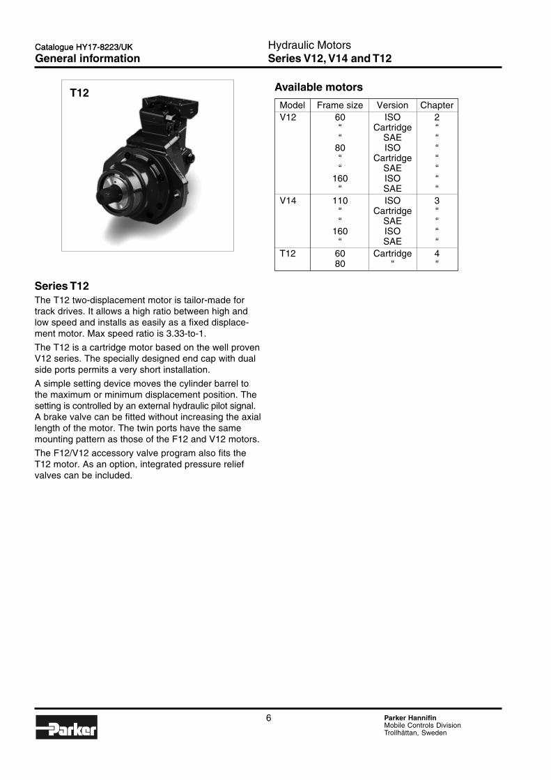
Series T12The T12 two-displacement motor is tailor-made fortrack drives. It allows a high ratio between high andlow speed and installs as easily as a fixed displace-ment motor. Max speed ratio is 3.33-to-1.
The T12 is a cartridge motor based on the well provenV12 series. The specially designed end cap with dualside ports permits a very short installation.
A simple setting device moves the cylinder barrel tothe maximum or minimum displacement position. Thesetting is controlled by an external hydraulic pilot signal.A brake valve can be fitted without increasing the axiallength of the motor. The twin ports have the samemounting pattern as those of the F12 and V12 motors.
The F12/V12 accessory valve program also fits theT12 motor. As an option, integrated pressure reliefvalves can be included.
Catalogue HY17-8223/UK
General information
7 Parker HannifinMobile Controls DivisionTrollhättan, Sweden
Hydraulic MotorsSeries V12
2
Catalogue HY17-8223/UK
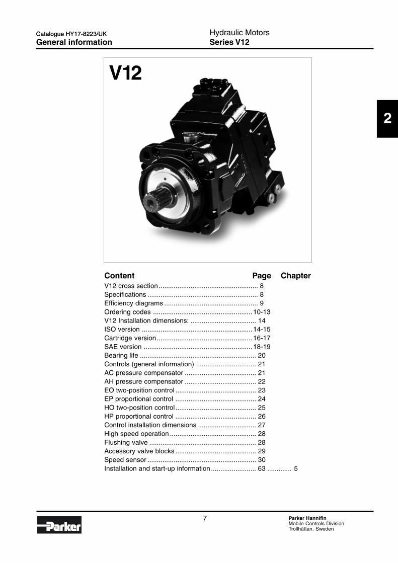
V12
Catalogue HY17-8223/UK
General information
Content Page ChapterV12 cross section ..................................................... 8Specifications ........................................................... 8Efficiency diagrams .................................................. 9Ordering codes .....................................................10-13V12 Installation dimensions: ................................... 14ISO version ...........................................................14-15Cartridge version...................................................16-17SAE version ..........................................................18-19Bearing life .............................................................. 20Controls (general information) ................................ 21AC pressure compensator ...................................... 21AH pressure compensator ...................................... 22EO two-position control ........................................... 23EP proportional control ........................................... 24HO two-position control ........................................... 25HP proportional control ........................................... 26Control installation dimensions ............................... 27High speed operation .............................................. 28Flushing valve ......................................................... 28Accessory valve blocks ........................................... 29Speed sensor .......................................................... 30Installation and start-up information ........................ 63 ............. 5
8 Parker HannifinMobile Controls DivisionTrollhättan, Sweden
Hydraulic MotorsSeries V12
Catalogue HY17-8223/UK
1 2 3 4 5 6 7 8 9 10
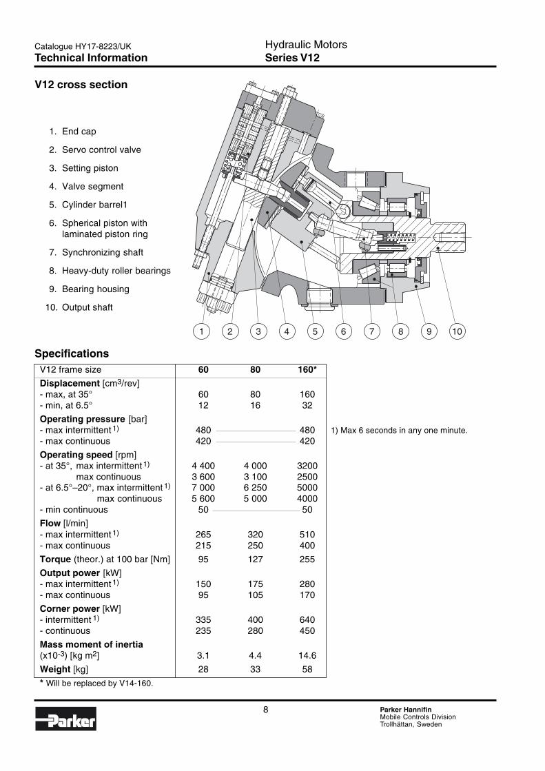
SpecificationsV12 frame size 60 80 160*
Displacement [cm3/rev]- max, at 35° 60 80 160- min, at 6.5° 12 16 32
Operating pressure [bar]- max intermittent 1) 480 480 1) Max 6 seconds in any one minute.- max continuous 420 420
Operating speed [rpm]- at 35°, max intermittent1) 4 400 4 000 3200
max continuous 3 600 3 100 2500- at 6.5°–20°, max intermittent 1) 7 000 6 250 5000
max continuous 5 600 5 000 4000- min continuous 50 50
Flow [l/min]- max intermittent 1) 265 320 510- max continuous 215 250 400
Torque (theor.) at 100 bar [Nm] 95 127 255
Output power [kW]- max intermittent 1) 150 175 280- max continuous 95 105 170
Corner power [kW]- intermittent 1) 335 400 640- continuous 235 280 450
Mass moment of inertia(x10-3) [kg m2] 3.1 4.4 14.6
Weight [kg] 28 33 58
* Will be replaced by V14-160.
V12 cross section
1. End cap
2. Servo control valve
3. Setting piston
4. Valve segment
5. Cylinder barrel1
6. Spherical piston withlaminated piston ring
7. Synchronizing shaft
8. Heavy-duty roller bearings
9. Bearing housing
10. Output shaft
Technical Information
9 Parker HannifinMobile Controls DivisionTrollhättan, Sweden
Hydraulic MotorsSeries V12
2
Catalogue HY17-8223/UK
[%]
100
90
800 1000 2000 3000 4000 5000
[%]
100
90
800 1000 2000 3000 4000 5000
V12-60
[%]
100
90
800 1000 2000 3000 4000 5000
[%]
100
90
800 1000 2000 3000 4000 5000
V12-80
[%]
100
90
800 1000 2000 3000 4000 5000
[%]
100
90
800 1000 2000 3000 4000 5000
V12-160
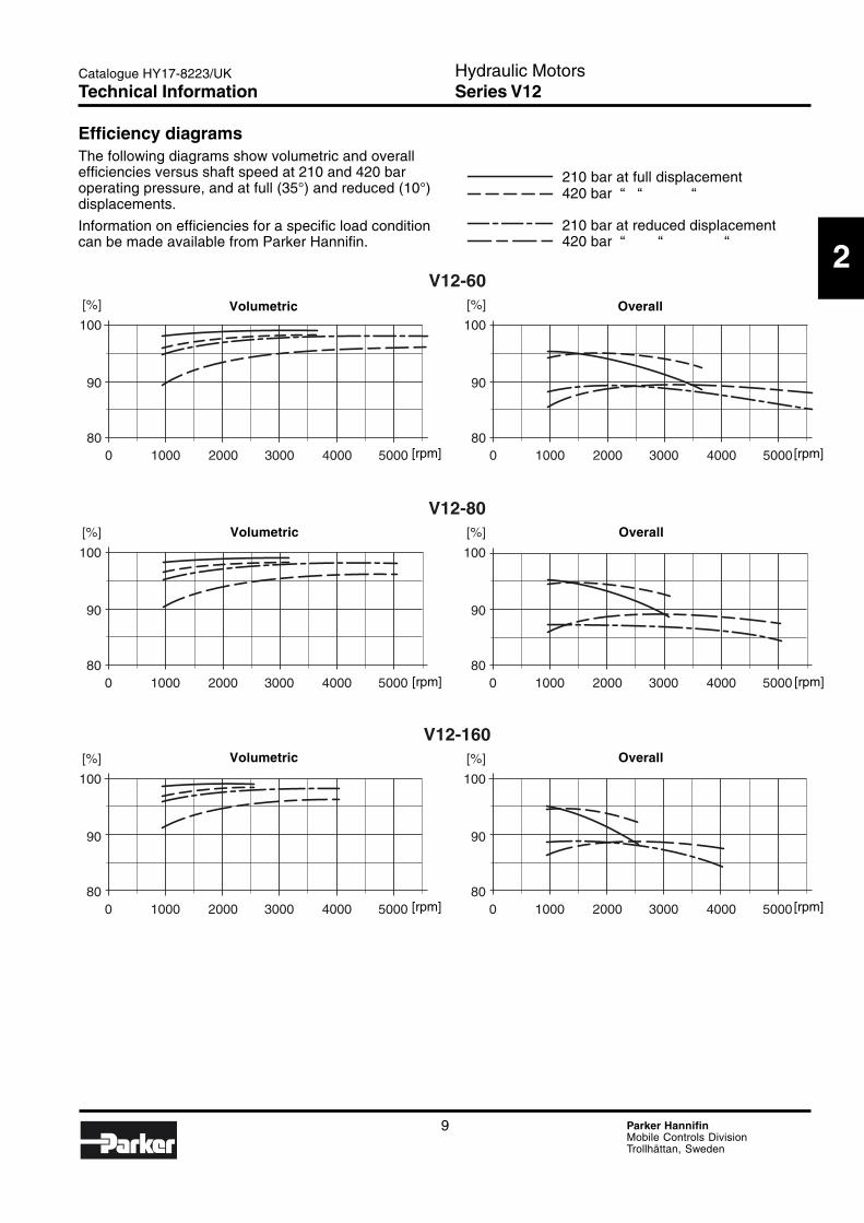
Efficiency diagramsThe following diagrams show volumetric and overallefficiencies versus shaft speed at 210 and 420 baroperating pressure, and at full (35°) and reduced (10°)displacements.
Information on efficiencies for a specific load conditioncan be made available from Parker Hannifin.
210 bar at full displacement420 bar “ “ “
210 bar at reduced displacement420 bar “ “ “
Volumetric Overall
Volumetric Overall
Volumetric Overall
[rpm]
[rpm]
[rpm]
[rpm]
[rpm]
[rpm]
Technical Information

10 Parker HannifinMobile Controls DivisionTrollhättan, Sweden
Hydraulic MotorsSeries V12
Catalogue HY17-8223/UK
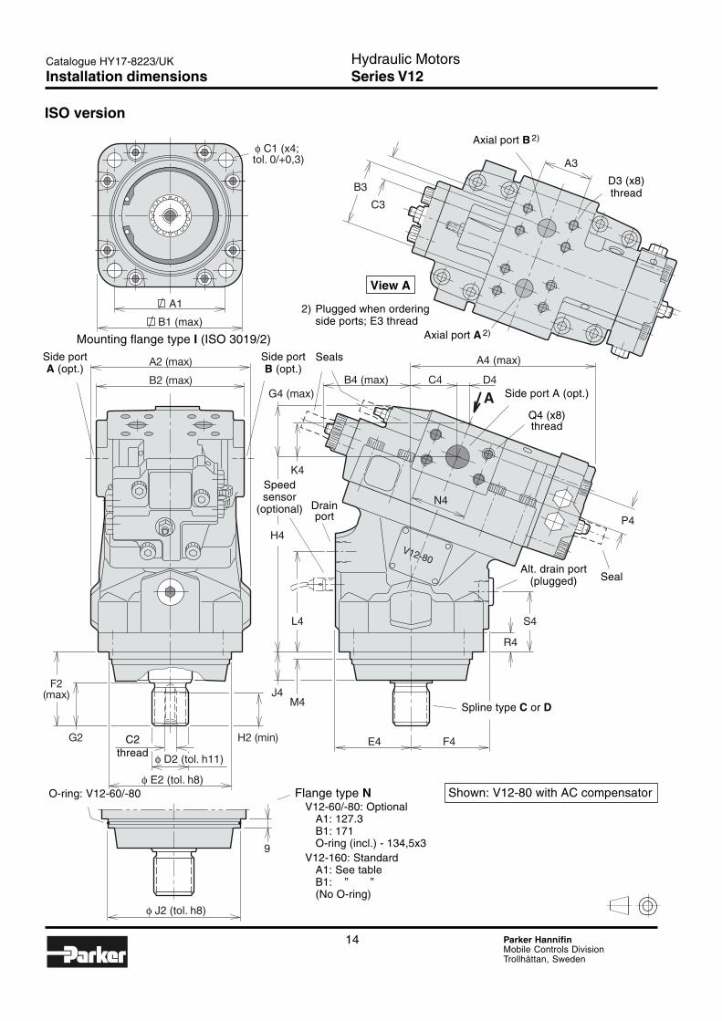
ISO version (basic configuration)
Code Frame size[cm3/rev]
060 60080 80160 160
Frame size 60 80 160
Code FunctionM Motor;
normal endcap position:EO, EP,HO and HP x x x
T Motor;normal endcap position:AC and AH x x x
Frame size 60 80 160
Code Main portsA SAE flange;
metric threads,rear ports x x x
F SAE flange;metric threads,side ports x x x
Frame size 60 80 160
Code Mounting flangeI ISO flange x x –N ISO flange (x) (x) x
Frame size 60 80 160
Code Shaft sealH NBR (nitirile) x x xV FPM (high temp.; fluorocarbon) (x) (x) (x)
Frame size 60 80 160
Code Shaft (DIN 5480)C Spline (x) (x) (x)D Spline x x x
x: Available (x): Optional – : Not available
Max and mindisplacement[cm3/rev]
Code Speed sensor(refer to page 30)
S Speed sensor(not installed)
P Prepared forspeed sensor
Code StatusD Control pressure setting;
max and min displacementscrews sealed
Version numberFactory assignedfor special versions
V12 – – – – – – – – /
Motor Frame Func- Main Mount.- Shaft Shaft Version Status Speed Max Mintype size tion ports flange seal number sensor displacement
Ordering codes
11 Parker HannifinMobile Controls DivisionTrollhättan, Sweden
Hydraulic MotorsSeries V12
2
Catalogue HY17-8223/UK
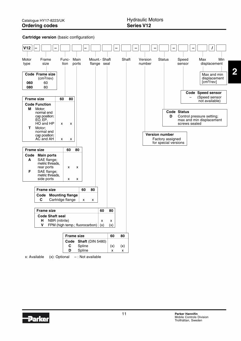
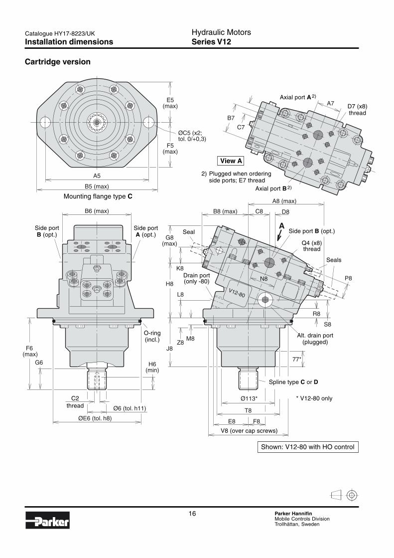
Cartridge version (basic configuration)
Code Frame size(cm3/rev)
060 60080 80
Frame size 60 80
Code FunctionM Motor;
normal endcap position:EO, EP,HO and HP x x
T Motor;normal endcap position:AC and AH x x
Frame size 60 80
Code Main portsA SAE flange;
metric threads,rear ports x x
F SAE flange;metric threads,side ports x x
Frame size 60 80
Code Mounting flangeC Cartridge flange x x
Frame size 60 80
Code Shaft sealH NBR (nitirile) x xV FPM (high temp.; fluorocarbon) (x) (x)
Frame size 60 80
Code Shaft (DIN 5480)C Spline (x) (x)D Spline x x
x: Available (x): Optional – : Not available
Max and mindisplacement[cm3/rev]
Code Speed sensor– (Speed sensor
not available)
Code StatusD Control pressure setting;
max and min displacementscrews sealed
Version numberFactory assignedfor special versions
V12 – – – – – – – – /
Motor Frame Func- Main Mount.- Shaft Shaft Version Status Speed Max Mintype size tion ports flange seal number sensor displacement
Ordering codes
12 Parker HannifinMobile Controls DivisionTrollhättan, Sweden
Hydraulic MotorsSeries V12
Catalogue HY17-8223/UK
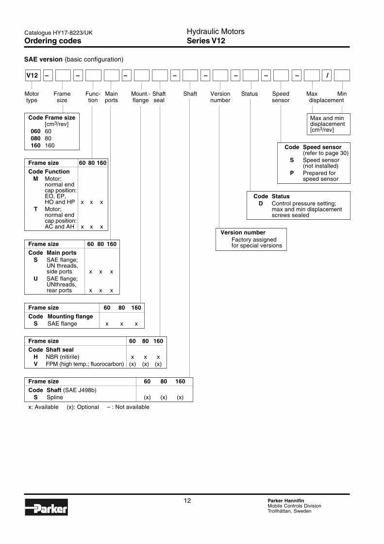
SAE version (basic configuration)
Max and mindisplacement[cm3/rev]
Code Speed sensor(refer to page 30)
S Speed sensor(not installed)
P Prepared forspeed sensor
Code StatusD Control pressure setting;
max and min displacementscrews sealed
Version numberFactory assignedfor special versions
Code Frame size[cm3/rev]
060 60080 80160 160
Frame size 60 80 160
Code FunctionM Motor;
normal endcap position:EO, EP,HO and HP x x x
T Motor;normal endcap position:AC and AH x x x
Frame size 60 80 160
Code Main portsS SAE flange;
UN threads,side ports x x x
U SAE flange;UNthreads,rear ports x x x
Frame size 60 80 160
Code Mounting flangeS SAE flange x x x
Frame size 60 80 160
Code Shaft sealH NBR (nitirile) x x xV FPM (high temp.; fluorocarbon) (x) (x) (x)
Frame size 60 80 160
Code Shaft (SAE J498b)S Spline (x) (x) (x)
x: Available (x): Optional – : Not available
V12 – – – – – – – – /
Motor Frame Func- Main Mount.- Shaft Shaft Version Status Speed Max Mintype size tion ports flange seal number sensor displacement
Ordering codes
13 Parker HannifinMobile Controls DivisionTrollhättan, Sweden
Hydraulic MotorsSeries V12
2
Catalogue HY17-8223/UK
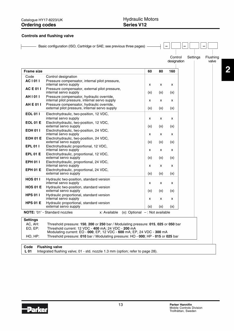
Controls and flushing valve
Frame size 60 80 160
Code Control designationAC I 01 I Pressure compensator, internal pilot pressure,
internal servo supply x x xAC E 01 I Pressure compensator, external pilot pressure,
internal servo supply (x) (x) (x)AH I 01 I Pressure compensator, hydraulic override,
internal pilot pressure, internal servo supply x x xAH E 01 I Pressure compensator, hydraulic override,
external pilot pressure, internal servo supply (x) (x) (x)
EOL 01 I Electrohydraulic, two-position, 12 VDC,internal servo supply x x x
EOL 01 E Electrohydraulic, two-position, 12 VDC,external servo supply (x) (x) (x)
EOH 01 I Electrohydraulic, two-position, 24 VDC,internal servo supply x x x
EOH 01 E Electrohydraulic, two-position, 24 VDC,external servo supply (x) (x) (x)
EPL 01 I Electrohydraulic proportional, 12 VDC,internal servo supply x x x
EPL 01 E Electrohydraulic, proportional, 12 VDC,external servo supply (x) (x) (x)
EPH 01 I Electrohydraulic, proportional, 24 VDC,internal servo supply x x x
EPH 01 E Electrohydraulic, proportional, 24 VDC,external servo supply (x) (x) (x)
HOS 01 I Hydraulic two-position, standard versioninternal servo supply x x x
HOS 01 E Hydraulic two-position, standard versionexternal servo supply (x) (x) (x)
HPS 01 I Hydraulic proportional, standard versioninternal servo supply x x x
HPS 01 E Hydraulic proportional, standard versionexternal servo supply (x) (x) (x)
NOTE: ’01’ - Standard nozzles x: Available (x): Optional – : Not available
SettingsAC, AH: Threshold pressure: 150, 200 or 250 bar / Modulating pressure: 015, 025 or 050 barEO, EP: Threshold current: 12 VDC - 400 mA; 24 VDC - 200 mA
Modulating current: EO - 000; EP, 12 VDC - 600 mA; EP, 24 VDC - 300 mAHO, HP: Threshold pressure: 010 bar / Modulating pressure: HO - 000; HP - 015 or 025 bar
Code Flushing valveL 01 Integrated flushing valve; 01 - std. nozzle 1.3 mm (option; refer to page 28).
Basic configuration (ISO, Cartridge or SAE; see previous three pages) – – –
Control Settings Flushingdesignation valve
Ordering codes
14 Parker HannifinMobile Controls DivisionTrollhättan, Sweden
Hydraulic MotorsSeries V12
Catalogue HY17-8223/UK
V12-80
φ C1 (x4; tol. 0/+0,3)
B1 (max)
A1
C3
A3
B3
A2 (max) A4 (max)
B4 (max) C4
K4
N4
H4
J4
L4
M4
E4 F4
G4 (max)
P4
S4
R4
D4B2 (max)
F2(max)
G2 H2 (min)
9
φ D2 (tol. h11)
φ E2 (tol. h8)
φ J2 (tol. h8)
A
ISO version
Mounting flange type I (ISO 3019/2)Side portA (opt.)
Side portB (opt.)
View A
2) Plugged when orderingside ports; E3 thread
Axial port B 2)
D3 (x8)thread
Axial port A 2)
C2thread
O-ring: V12-60/-80 Flange type NV12-60/-80: Optional
A1: 127.3B1: 171O-ring (incl.) - 134,5x3
V12-160: StandardA1: See tableB1: ” ”(No O-ring)
Shown: V12-80 with AC compensator
Spline type C or D
Alt. drain port(plugged)
Side port A (opt.)
Q4 (x8)thread
Seals
Seal
Drainport
Speedsensor
(optional)
Installation dimensions
15 Parker HannifinMobile Controls DivisionTrollhättan, Sweden
Hydraulic MotorsSeries V12
2
Catalogue HY17-8223/UK
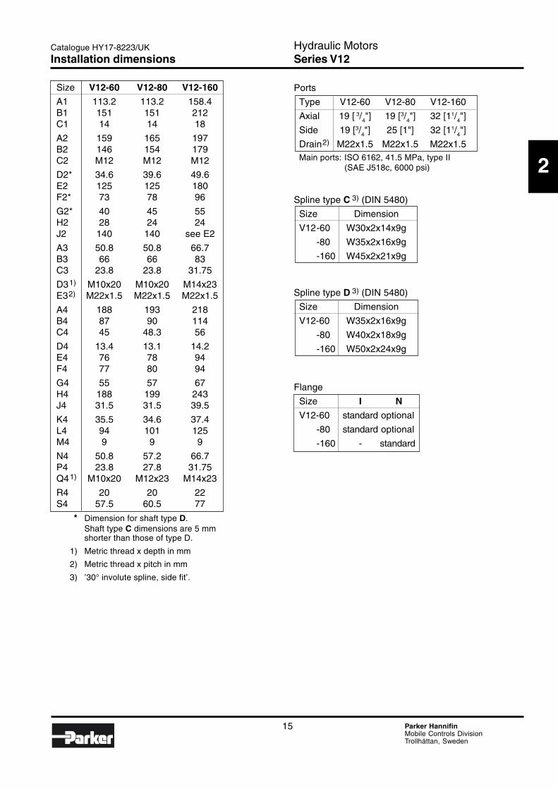
Size V12-60 V12-80 V12-160
A1 113.2 113.2 158.4B1 151 151 212C1 14 14 18
A2 159 165 197B2 146 154 179C2 M12 M12 M12
D2* 34.6 39.6 49.6E2 125 125 180F2* 73 78 96
G2* 40 45 55H2 28 24 24J2 140 140 see E2
A3 50.8 50.8 66.7B3 66 66 83C3 23.8 23.8 31.75
D31) M10x20 M10x20 M14x23E32) M22x1.5 M22x1.5 M22x1.5
A4 188 193 218B4 87 90 114C4 45 48.3 56
D4 13.4 13.1 14.2E4 76 78 94F4 77 80 94
G4 55 57 67H4 188 199 243J4 31.5 31.5 39.5
K4 35.5 34.6 37.4L4 94 101 125M4 9 9 9
N4 50.8 57.2 66.7P4 23.8 27.8 31.75Q41) M10x20 M12x23 M14x23
R4 20 20 22S4 57.5 60.5 77
* Dimension for shaft type D.Shaft type C dimensions are 5 mmshorter than those of type D.
1) Metric thread x depth in mm
2) Metric thread x pitch in mm
3) ’30° involute spline, side fit’.
Ports
Type V12-60 V12-80 V12-160
Axial 19 [ 3/4"] 19 [3/
4"] 32 [11/
4"]
Side 19 [3/4"] 25 [1"] 32 [11/
4"]
Drain2) M22x1.5 M22x1.5 M22x1.5Main ports: ISO 6162, 41.5 MPa, type II
(SAE J518c, 6000 psi)
Spline type C 3) (DIN 5480)
Size Dimension
V12-60 W30x2x14x9g
-80 W35x2x16x9g
-160 W45x2x21x9g
Spline type D 3) (DIN 5480)
Size Dimension
V12-60 W35x2x16x9g
-80 W40x2x18x9g
-160 W50x2x24x9g
Flange
Size I N
V12-60 standard optional
-80 standard optional
-160 - standard
Installation dimensions
16 Parker HannifinMobile Controls DivisionTrollhättan, Sweden
Hydraulic MotorsSeries V12
Catalogue HY17-8223/UK
ØC5 (x2; tol. 0/+0,3)
E5(max)
F5(max)
A5
B7
C7
A7
B5 (max)
B6 (max)
F6 (max)
G6
Ø6 (tol. h11)
ØE6 (tol. h8)
A
A8 (max)
C8
K8
L8
Z8M8
T8
R8
S8
P8
E8 F8
G8(max)
H8
J8
H6(min)
D8
N8
B8 (max)
V12-80
77*
Ø113*
Cartridge version
Side portB (opt.)
Side portA (opt.)
View A
2) Plugged when orderingside ports; E7 thread
Axial port A 2)
D7 (x8)thread
Axial port B 2)
C2thread
Shown: V12-80 with HO control
Spline type C or D
Alt. drain port(plugged)
Seal Side port B (opt.)
Q4 (x8)thread
Seals
V8 (over cap screws)
O-ring(incl.)
Mounting flange type C
Drain port(only -80)
Installation dimensions
* V12-80 only
17 Parker HannifinMobile Controls DivisionTrollhättan, Sweden
Hydraulic MotorsSeries V12
2
Catalogue HY17-8223/UK
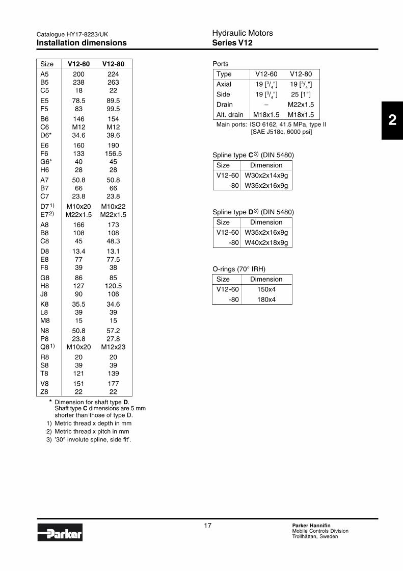
Size V12-60 V12-80
A5 200 224B5 238 263C5 18 22
E5 78.5 89.5F5 83 99.5
B6 146 154C6 M12 M12D6* 34.6 39.6
E6 160 190F6 133 156.5G6* 40 45H6 28 28
A7 50.8 50.8B7 66 66C7 23.8 23.8
D71) M10x20 M10x22E72) M22x1.5 M22x1.5
A8 166 173B8 108 108C8 45 48.3
D8 13.4 13.1E8 77 77.5F8 39 38
G8 86 85H8 127 120.5J8 90 106
K8 35.5 34.6L8 39 39M8 15 15
N8 50.8 57.2P8 23.8 27.8Q81) M10x20 M12x23
R8 20 20S8 39 39T8 121 139
V8 151 177Z8 22 22
* Dimension for shaft type D.Shaft type C dimensions are 5 mmshorter than those of type D.
1) Metric thread x depth in mm2) Metric thread x pitch in mm3) ’30° involute spline, side fit’.
Ports
Type V12-60 V12-80
Axial 19 [3/4"] 19 [3/4"]
Side 19 [3/4"] 25 [1"]
Drain – M22x1.5
Alt. drain M18x1.5 M18x1.5Main ports: ISO 6162, 41.5 MPa, type II
[SAE J518c, 6000 psi]
Spline type C3) (DIN 5480)
Size Dimension
V12-60 W30x2x14x9g
-80 W35x2x16x9g
Spline type D3) (DIN 5480)
Size Dimension
V12-60 W35x2x16x9g
-80 W40x2x18x9g
O-rings (70° IRH)
Size Dimension
V12-60 150x4
-80 180x4
Installation dimensions
18 Parker HannifinMobile Controls DivisionTrollhättan, Sweden
Hydraulic MotorsSeries V12
Catalogue HY17-8223/UK
V12-80
A9
φ C9 (x4;tol. 0/+0,3)
B9 (max)
A12 (max)
B12 (max)
A10 (max)
φ E10 (tol. h8)
φ D10 (tol. 0/-0,13)
B10 (max)
A
8
H10 (min)
G10
C11
B11
A11
C12
H12
J12
L12S12
P12
R12
E12 F12
K12
G12(max)
D12
N11
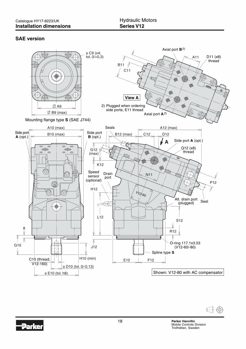
SAE version
Mounting flange type S (SAE J744)
Side portA (opt.)
Side portB (opt.)
View A
2) Plugged when orderingside ports; E11 thread
Axial port B 2)
D11 (x8)thread
Axial port A 2)
C10 (thread;V12-160)
Shown: V12-80 with AC compensator
Spline type S
Alt. drain port(plugged)
Seals
Side port A (opt.)
Q12 (x8)thread
O-ring 117.1x3.53(V12-60/-80)
Seal
Speedsensor
(optional)
Drainport
Installation dimensions
19 Parker HannifinMobile Controls DivisionTrollhättan, Sweden
Hydraulic MotorsSeries V12
2
Catalogue HY17-8223/UK
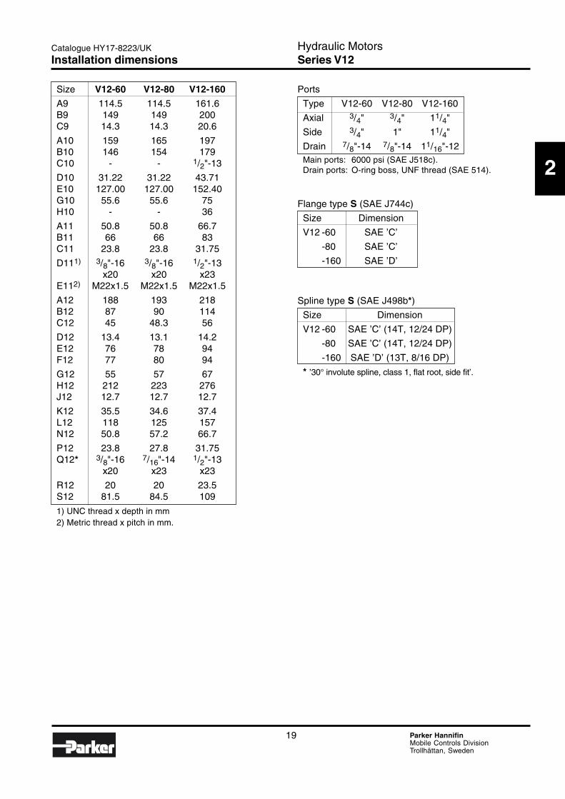
Size V12-60 V12-80 V12-160
A9 114.5 114.5 161.6B9 149 149 200C9 14.3 14.3 20.6
A10 159 165 197B10 146 154 179C10 - - 1/2"-13
D10 31.22 31.22 43.71E10 127.00 127.00 152.40G10 55.6 55.6 75H10 - - 36
A11 50.8 50.8 66.7B11 66 66 83C11 23.8 23.8 31.75
D111) 3/8"-16 3/8"-16 1/2"-13x20 x20 x23
E112) M22x1.5 M22x1.5 M22x1.5
A12 188 193 218B12 87 90 114C12 45 48.3 56
D12 13.4 13.1 14.2E12 76 78 94F12 77 80 94
G12 55 57 67H12 212 223 276J12 12.7 12.7 12.7
K12 35.5 34.6 37.4L12 118 125 157N12 50.8 57.2 66.7
P12 23.8 27.8 31.75Q12* 3/8"-16 7/16"-14 1/2"-13
x20 x23 x23
R12 20 20 23.5S12 81.5 84.5 109
1) UNC thread x depth in mm2) Metric thread x pitch in mm.
Ports
Type V12-60 V12-80 V12-160
Axial 3/4" 3/4" 11/4"
Side 3/4" 1" 11/4"
Drain 7/8"-14 7/8"-14 11/16"-12Main ports: 6000 psi (SAE J518c).Drain ports: O-ring boss, UNF thread (SAE 514).
Flange type S (SAE J744c)
Size Dimension
V12 -60 SAE ’C’
-80 SAE ’C’
-160 SAE ’D’
Spline type S (SAE J498b*)
Size Dimension
V12 -60 SAE ’C’ (14T, 12/24 DP)
-80 SAE ’C’ (14T, 12/24 DP)
-160 SAE ’D’ (13T, 8/16 DP)
* ’30° involute spline, class 1, flat root, side fit’.
Installation dimensions
20 Parker HannifinMobile Controls DivisionTrollhättan, Sweden
Hydraulic MotorsSeries V12
Catalogue HY17-8223/UK
F α F
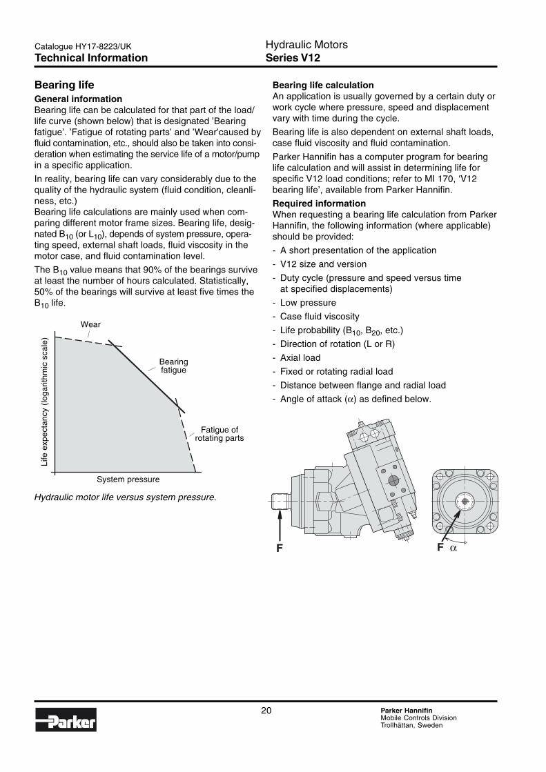
Bearing lifeGeneral informationBearing life can be calculated for that part of the load/life curve (shown below) that is designated ’Bearingfatigue’. ’Fatigue of rotating parts’ and ’Wear’caused byfluid contamination, etc., should also be taken into consi-deration when estimating the service life of a motor/pumpin a specific application.
In reality, bearing life can vary considerably due to thequality of the hydraulic system (fluid condition, cleanli-ness, etc.)Bearing life calculations are mainly used when com-paring different motor frame sizes. Bearing life, desig-nated B10 (or L10), depends of system pressure, opera-ting speed, external shaft loads, fluid viscosity in themotor case, and fluid contamination level.
The B10 value means that 90% of the bearings surviveat least the number of hours calculated. Statistically,50% of the bearings will survive at least five times theB10 life.
Bearing life calculationAn application is usually governed by a certain duty orwork cycle where pressure, speed and displacementvary with time during the cycle.
Bearing life is also dependent on external shaft loads,case fluid viscosity and fluid contamination.
Parker Hannifin has a computer program for bearinglife calculation and will assist in determining life forspecific V12 load conditions; refer to MI 170, ‘V12bearing life’, available from Parker Hannifin.
Required informationWhen requesting a bearing life calculation from ParkerHannifin, the following information (where applicable)should be provided:
- A short presentation of the application
- V12 size and version
- Duty cycle (pressure and speed versus timeat specified displacements)
- Low pressure
- Case fluid viscosity
- Life probability (B10, B20, etc.)
- Direction of rotation (L or R)
- Axial load
- Fixed or rotating radial load
- Distance between flange and radial load
- Angle of attack (α) as defined below.
Hydraulic motor life versus system pressure.
Wear
Bearingfatigue
Fatigue ofrotating parts
System pressure
Life
exp
ecta
ncy
(loga
rithm
ic s
cale
)
Technical Information
21 Parker HannifinMobile Controls DivisionTrollhättan, Sweden
Hydraulic MotorsSeries V12
2
Catalogue HY17-8223/UK
Max
Min
X4 X2 A
X4 X2 A
X6 X1 B
X6
X5
X1 B
Max
Min
Max
Min
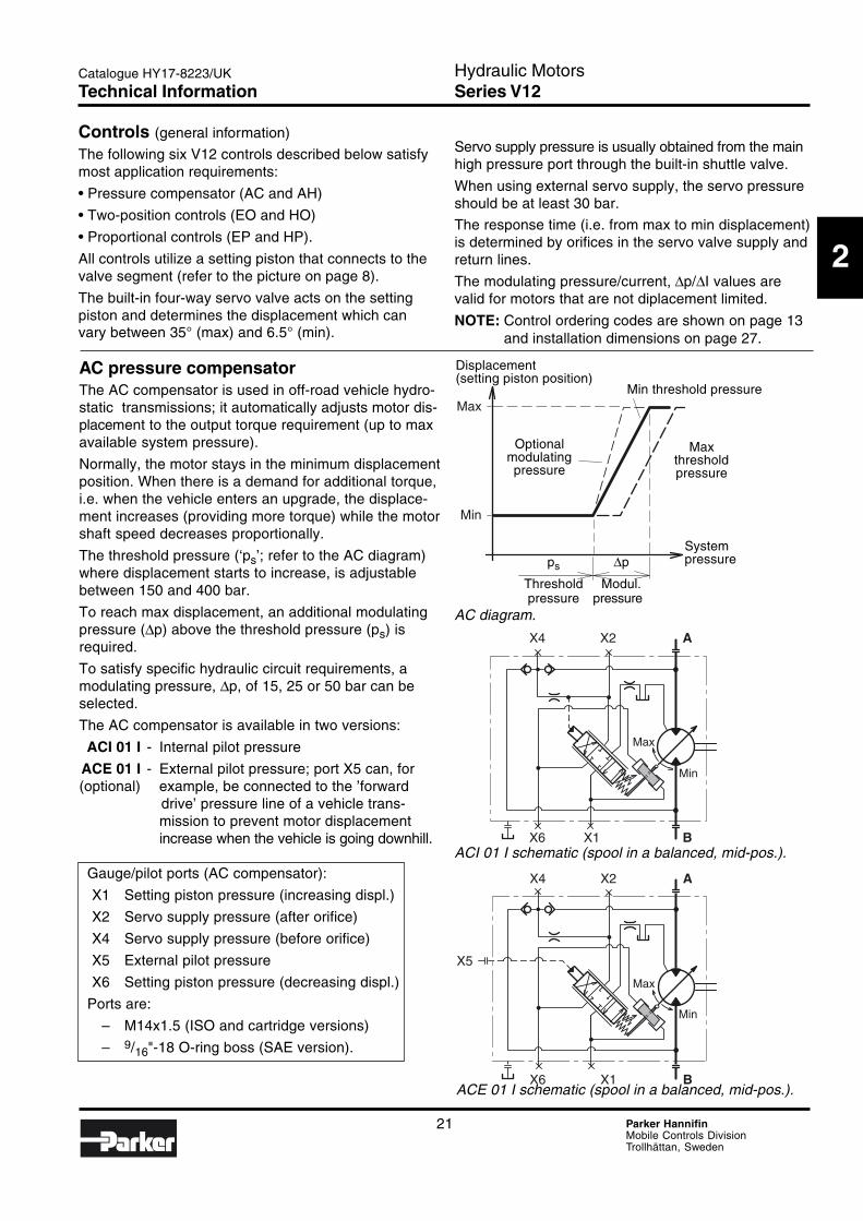
AC pressure compensatorThe AC compensator is used in off-road vehicle hydro-static transmissions; it automatically adjusts motor dis-placement to the output torque requirement (up to maxavailable system pressure).
Normally, the motor stays in the minimum displacementposition. When there is a demand for additional torque,i.e. when the vehicle enters an upgrade, the displace-ment increases (providing more torque) while the motorshaft speed decreases proportionally.
The threshold pressure (‘ps’; refer to the AC diagram)where displacement starts to increase, is adjustablebetween 150 and 400 bar.
To reach max displacement, an additional modulatingpressure (∆p) above the threshold pressure (ps) isrequired.
To satisfy specific hydraulic circuit requirements, amodulating pressure, ∆p, of 15, 25 or 50 bar can beselected.
The AC compensator is available in two versions:
ACI 01 I - Internal pilot pressure
ACE 01 I - External pilot pressure; port X5 can, for(optional) example, be connected to the ’forward
drive’ pressure line of a vehicle trans-mission to prevent motor displacementincrease when the vehicle is going downhill.
Gauge/pilot ports (AC compensator):
X1 Setting piston pressure (increasing displ.)
X2 Servo supply pressure (after orifice)
X4 Servo supply pressure (before orifice)
X5 External pilot pressure
X6 Setting piston pressure (decreasing displ.)
Ports are:
– M14x1.5 (ISO and cartridge versions)
– 9/16"-18 O-ring boss (SAE version).
Servo supply pressure is usually obtained from the mainhigh pressure port through the built-in shuttle valve.
When using external servo supply, the servo pressureshould be at least 30 bar.
The response time (i.e. from max to min displacement)is determined by orifices in the servo valve supply andreturn lines.
The modulating pressure/current, ∆p/∆I values arevalid for motors that are not diplacement limited.
NOTE: Control ordering codes are shown on page 13and installation dimensions on page 27.
Controls (general information)
The following six V12 controls described below satisfymost application requirements:
• Pressure compensator (AC and AH)
• Two-position controls (EO and HO)
• Proportional controls (EP and HP).
All controls utilize a setting piston that connects to thevalve segment (refer to the picture on page 8).
The built-in four-way servo valve acts on the settingpiston and determines the displacement which canvary between 35° (max) and 6.5° (min).
Displacement(setting piston position)
Min threshold pressure
Optionalmodulatingpressure
Maxthresholdpressure
Systempressureps ∆p
Threshold Modul.pressure pressure
AC diagram.
ACI 01 I schematic (spool in a balanced, mid-pos.).
ACE 01 I schematic (spool in a balanced, mid-pos.).
Technical Information
22 Parker HannifinMobile Controls DivisionTrollhättan, Sweden
Hydraulic MotorsSeries V12
Catalogue HY17-8223/UK
Max
Min
X4
X7
X2 A
X6 X1 B
Max
Min
X4
X7X5
X2 A
X6 X1 B
Max
Min
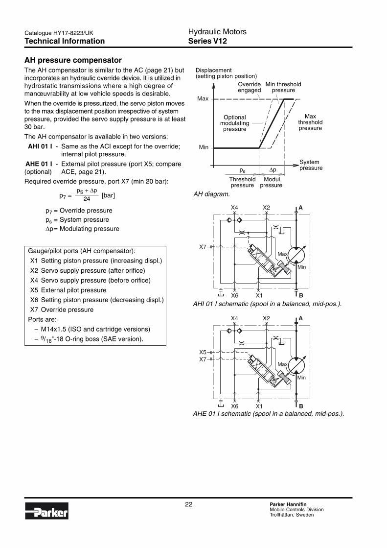
AH pressure compensatorThe AH compensator is similar to the AC (page 21) butincorporates an hydraulic override device. It is utilized inhydrostatic transmissions where a high degree ofmanœuvrability at low vehicle speeds is desirable.
When the override is pressurized, the servo piston movesto the max displacement position irrespective of systempressure, provided the servo supply pressure is at least30 bar.
The AH compensator is available in two versions:
AHI 01 I - Same as the ACI except for the override;internal pilot pressure.
AHE 01 I - External pilot pressure (port X5; compare(optional) ACE, page 21).
Required override pressure, port X7 (min 20 bar):
p7 = [bar]
p7 = Override pressureps = System pressure∆p= Modulating pressure
Gauge/pilot ports (AH compensator):
X1 Setting piston pressure (increasing displ.)
X2 Servo supply pressure (after orifice)
X4 Servo supply pressure (before orifice)
X5 External pilot pressure
X6 Setting piston pressure (decreasing displ.)
X7 Override pressure
Ports are:
– M14x1.5 (ISO and cartridge versions)
– 9/16"-18 O-ring boss (SAE version).
pS + ∆p
24
Displacement(setting piston position)
Override Min thresholdengaged pressure
Optionalmodulatingpressure
Maxthresholdpressure
Systempressureps ∆p
Threshold Modul.pressure pressure
AH diagram.
AHI 01 I schematic (spool in a balanced, mid-pos.).
AHE 01 I schematic (spool in a balanced, mid-pos.).
Technical Information
23 Parker HannifinMobile Controls DivisionTrollhättan, Sweden
Hydraulic MotorsSeries V12
2
Catalogue HY17-8223/UK
Max
Min
X4 X2 A
X6 X1 B
Max
Min
X4 X2 A
X6 X1 B
Max
Min
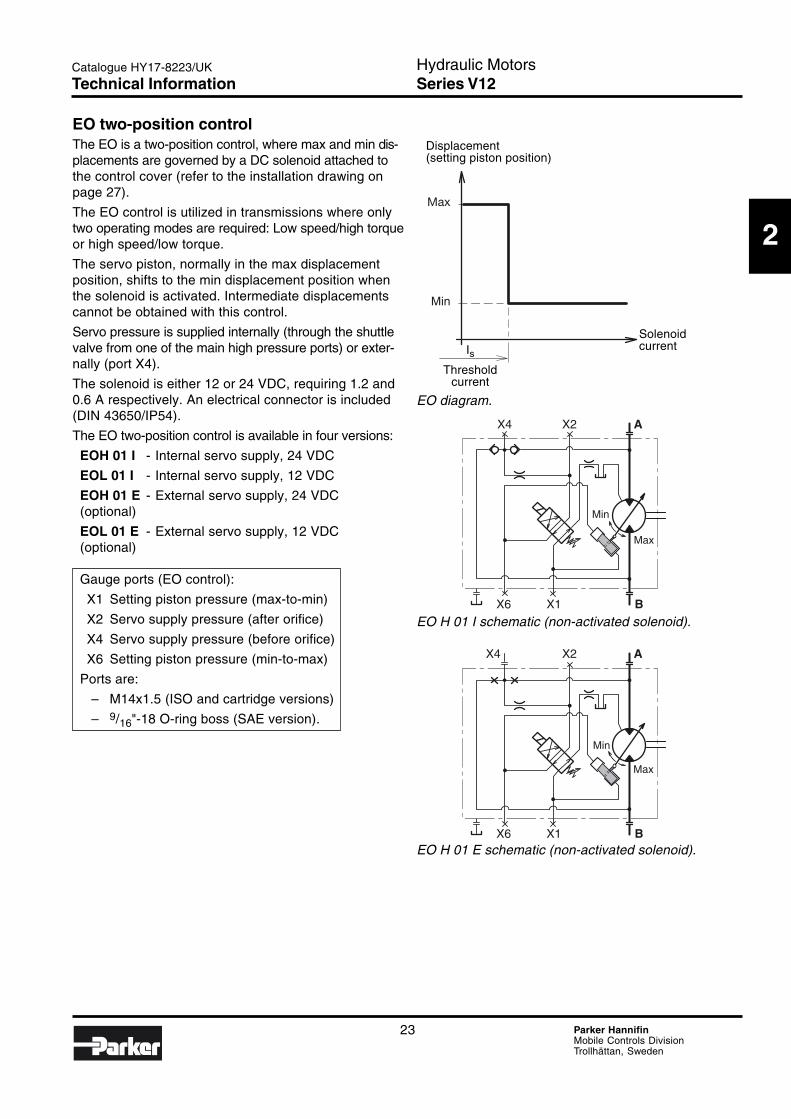
EO H 01 E schematic (non-activated solenoid).
Displacement(setting piston position)
SolenoidcurrentIs
Thresholdcurrent
EO diagram.
EO H 01 I schematic (non-activated solenoid).
EO two-position controlThe EO is a two-position control, where max and min dis-placements are governed by a DC solenoid attached tothe control cover (refer to the installation drawing onpage 27).
The EO control is utilized in transmissions where onlytwo operating modes are required: Low speed/high torqueor high speed/low torque.
The servo piston, normally in the max displacementposition, shifts to the min displacement position whenthe solenoid is activated. Intermediate displacementscannot be obtained with this control.
Servo pressure is supplied internally (through the shuttlevalve from one of the main high pressure ports) or exter-nally (port X4).
The solenoid is either 12 or 24 VDC, requiring 1.2 and0.6 A respectively. An electrical connector is included(DIN 43650/IP54).
The EO two-position control is available in four versions:
EOH 01 I - Internal servo supply, 24 VDC
EOL 01 I - Internal servo supply, 12 VDC
EOH 01 E - External servo supply, 24 VDC(optional)
EOL 01 E - External servo supply, 12 VDC(optional)
Gauge ports (EO control):
X1 Setting piston pressure (max-to-min)
X2 Servo supply pressure (after orifice)
X4 Servo supply pressure (before orifice)
X6 Setting piston pressure (min-to-max)
Ports are:
– M14x1.5 (ISO and cartridge versions)
– 9/16"-18 O-ring boss (SAE version).
Technical Information
24 Parker HannifinMobile Controls DivisionTrollhättan, Sweden
Hydraulic MotorsSeries V12
Catalogue HY17-8223/UK
X4 X2 A
X6 X1 B
Max
Min
X4 X2 A
X6 X1 B
Max
Min
Max
Min
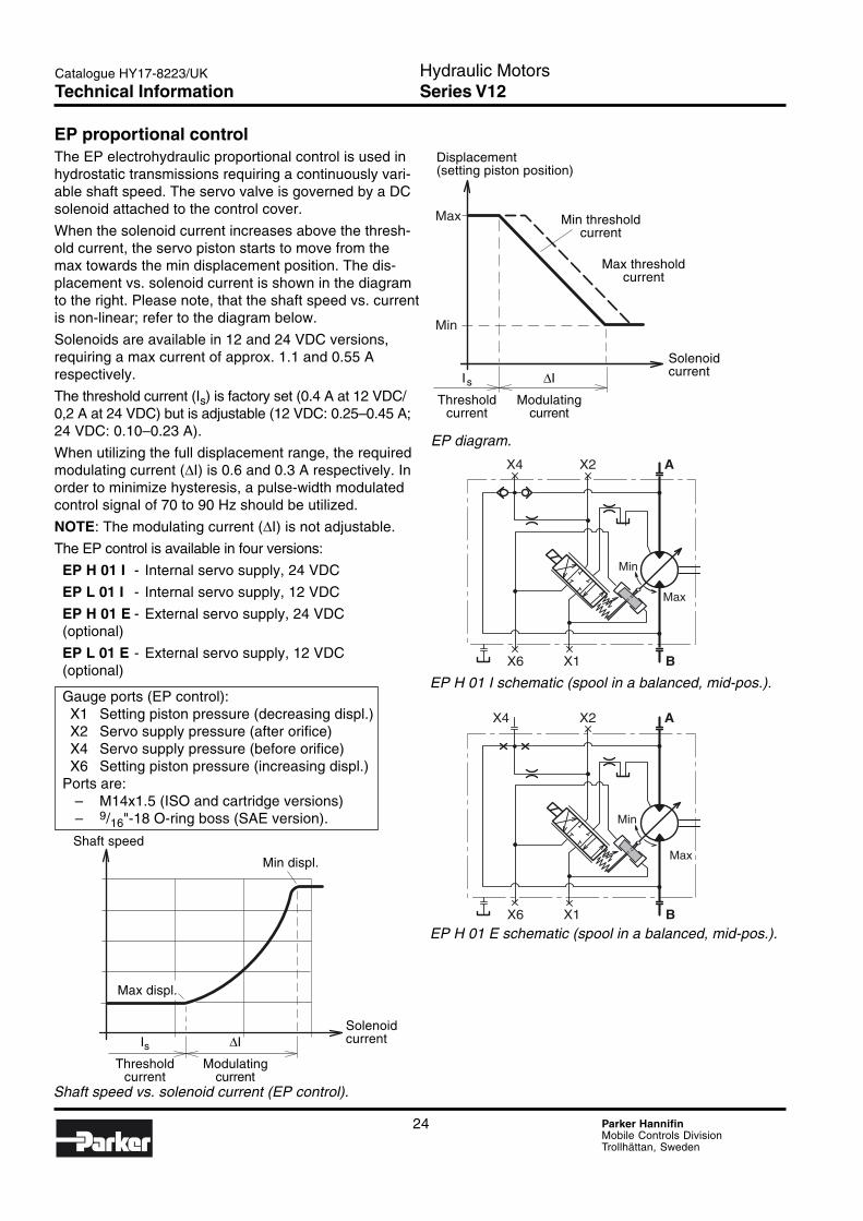
EP proportional controlThe EP electrohydraulic proportional control is used inhydrostatic transmissions requiring a continuously vari-able shaft speed. The servo valve is governed by a DCsolenoid attached to the control cover.
When the solenoid current increases above the thresh-old current, the servo piston starts to move from themax towards the min displacement position. The dis-placement vs. solenoid current is shown in the diagramto the right. Please note, that the shaft speed vs. currentis non-linear; refer to the diagram below.
Solenoids are available in 12 and 24 VDC versions,requiring a max current of approx. 1.1 and 0.55 Arespectively.
The threshold current (Is) is factory set (0.4 A at 12 VDC/0,2 A at 24 VDC) but is adjustable (12 VDC: 0.25–0.45 A;24 VDC: 0.10–0.23 A).
When utilizing the full displacement range, the requiredmodulating current (∆I) is 0.6 and 0.3 A respectively. Inorder to minimize hysteresis, a pulse-width modulatedcontrol signal of 70 to 90 Hz should be utilized.
NOTE: The modulating current (∆I) is not adjustable.
The EP control is available in four versions:
EP H 01 I - Internal servo supply, 24 VDC
EP L 01 I - Internal servo supply, 12 VDC
EP H 01 E - External servo supply, 24 VDC(optional)
EP L 01 E - External servo supply, 12 VDC(optional)
Gauge ports (EP control):X1 Setting piston pressure (decreasing displ.)X2 Servo supply pressure (after orifice)X4 Servo supply pressure (before orifice)X6 Setting piston pressure (increasing displ.)
Ports are:– M14x1.5 (ISO and cartridge versions)– 9/16"-18 O-ring boss (SAE version).
Shaft speed
Max displ.
SolenoidcurrentIs ∆I
Threshold Modulatingcurrent current
Min displ.
Shaft speed vs. solenoid current (EP control).
Displacement(setting piston position)
Min thresholdcurrent
Max thresholdcurrent
SolenoidcurrentIs ∆I
Threshold Modulatingcurrent current
EP diagram.
EP H 01 I schematic (spool in a balanced, mid-pos.).
EP H 01 E schematic (spool in a balanced, mid-pos.).
Technical Information
25 Parker HannifinMobile Controls DivisionTrollhättan, Sweden
Hydraulic MotorsSeries V12
2
Catalogue HY17-8223/UK
Max
Min
X4
X5
X2 A
X6 X1 B
Max
Min
X4
X5
X2 A
X6 X1 B
Max
Min
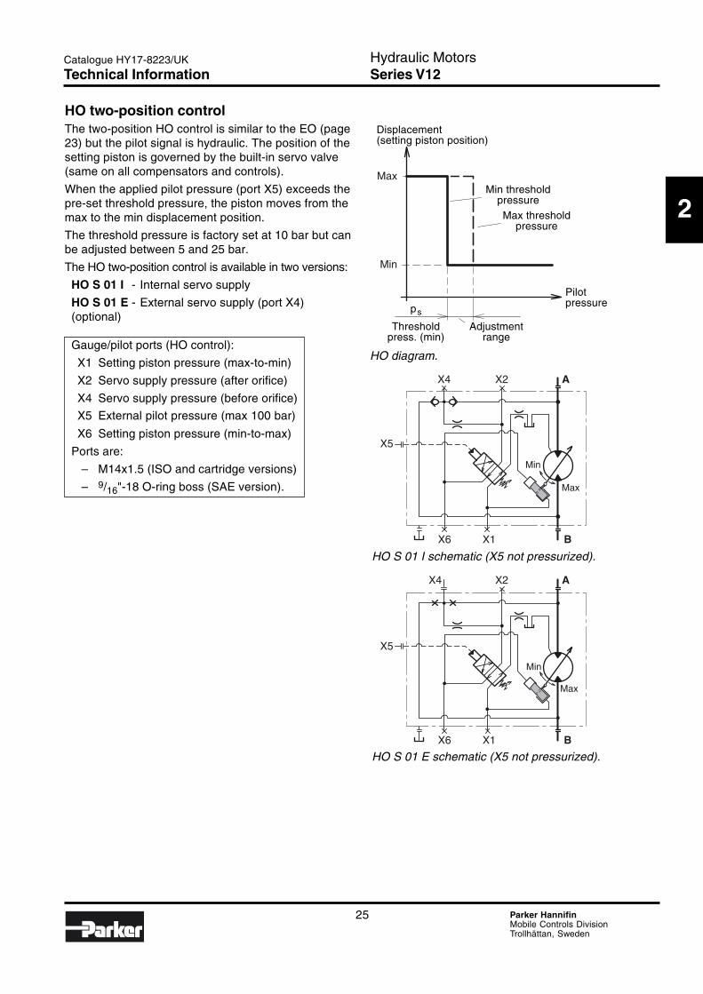
HO two-position controlThe two-position HO control is similar to the EO (page23) but the pilot signal is hydraulic. The position of thesetting piston is governed by the built-in servo valve(same on all compensators and controls).
When the applied pilot pressure (port X5) exceeds thepre-set threshold pressure, the piston moves from themax to the min displacement position.
The threshold pressure is factory set at 10 bar but canbe adjusted between 5 and 25 bar.
The HO two-position control is available in two versions:
HO S 01 I - Internal servo supply
HO S 01 E - External servo supply (port X4)(optional)
Gauge/pilot ports (HO control):
X1 Setting piston pressure (max-to-min)
X2 Servo supply pressure (after orifice)
X4 Servo supply pressure (before orifice)
X5 External pilot pressure (max 100 bar)
X6 Setting piston pressure (min-to-max)
Ports are:
– M14x1.5 (ISO and cartridge versions)
– 9/16"-18 O-ring boss (SAE version).
HO S 01 E schematic (X5 not pressurized).
Displacement(setting piston position)
Pilotpressureps
Threshold Adjustmentpress. (min) range
HO diagram.
HO S 01 I schematic (X5 not pressurized).
Min thresholdpressureMax threshold
pressure
Technical Information
26 Parker HannifinMobile Controls DivisionTrollhättan, Sweden
Hydraulic MotorsSeries V12
Catalogue HY17-8223/UK
Max
Min
X4
X5
X2 A
X6 X1 B
Max
Min
X4
X5
X2 A
X6 X1 B
Max
Min
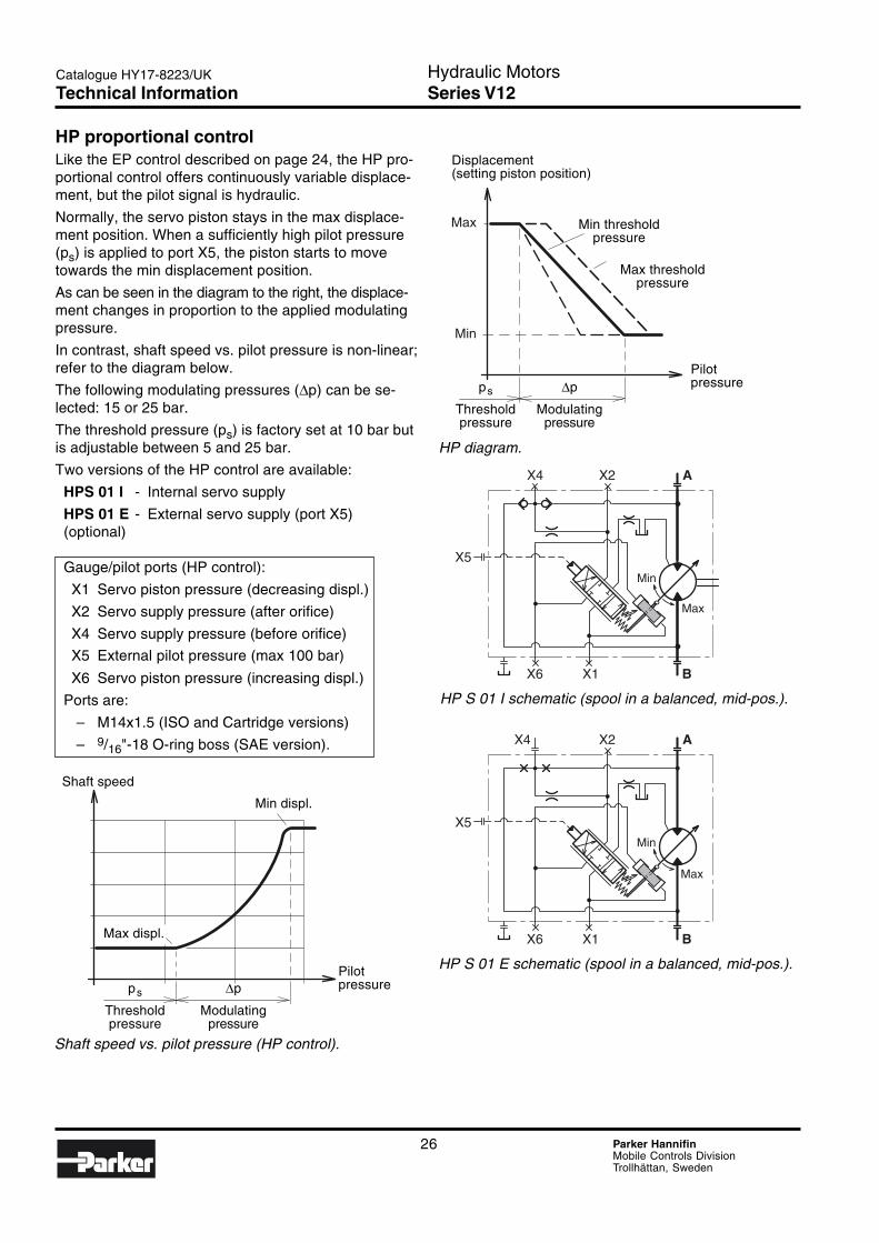
HP proportional controlLike the EP control described on page 24, the HP pro-portional control offers continuously variable displace-ment, but the pilot signal is hydraulic.
Normally, the servo piston stays in the max displace-ment position. When a sufficiently high pilot pressure(ps) is applied to port X5, the piston starts to movetowards the min displacement position.
As can be seen in the diagram to the right, the displace-ment changes in proportion to the applied modulatingpressure.
In contrast, shaft speed vs. pilot pressure is non-linear;refer to the diagram below.
The following modulating pressures (∆p) can be se-lected: 15 or 25 bar.
The threshold pressure (ps) is factory set at 10 bar butis adjustable between 5 and 25 bar.
Two versions of the HP control are available:
HPS 01 I - Internal servo supply
HPS 01 E - External servo supply (port X5)(optional)
Gauge/pilot ports (HP control):
X1 Servo piston pressure (decreasing displ.)
X2 Servo supply pressure (after orifice)
X4 Servo supply pressure (before orifice)
X5 External pilot pressure (max 100 bar)
X6 Servo piston pressure (increasing displ.)
Ports are:
– M14x1.5 (ISO and Cartridge versions)
– 9/16"-18 O-ring boss (SAE version).
Displacement(setting piston position)
Min thresholdpressure
Max thresholdpressure
Pilotpressureps ∆p
Threshold Modulatingpressure pressure
HP diagram.
HP S 01 I schematic (spool in a balanced, mid-pos.).
HP S 01 E schematic (spool in a balanced, mid-pos.).
Shaft speed vs. pilot pressure (HP control).
Shaft speed
Max displ.
Pilotpressureps ∆p
Threshold Modulatingpressure pressure
Min displ.
Technical Information
27 Parker HannifinMobile Controls DivisionTrollhättan, Sweden
Hydraulic MotorsSeries V12
2
Catalogue HY17-8223/UK
A1 A2
E1 E2
H1 H2
A3
A4
E3
H3
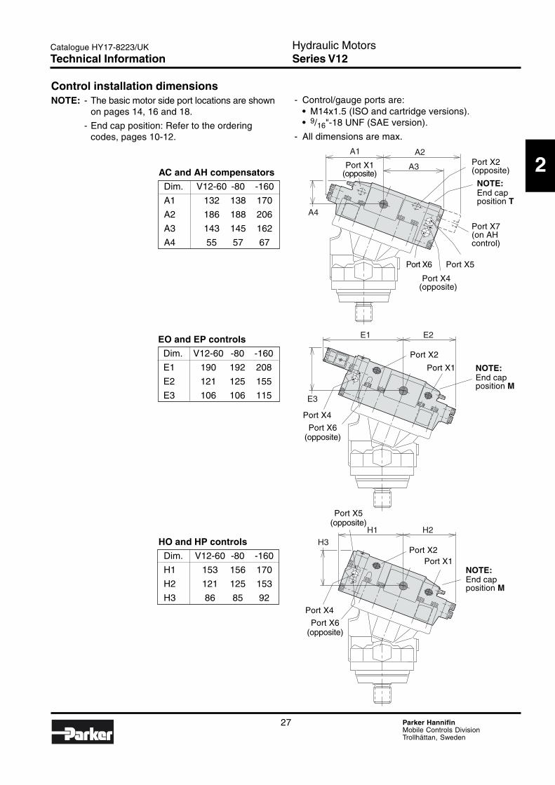
Control installation dimensionsNOTE: - The basic motor side port locations are shown
on pages 14, 16 and 18.
- End cap position: Refer to the orderingcodes, pages 10-12.
HO and HP controls
Dim. V12-60 -80 -160
H1 153 156 170
H2 121 125 153
H3 86 85 92
EO and EP controls
Dim. V12-60 -80 -160
E1 190 192 208
E2 121 125 155
E3 106 106 115
AC and AH compensators
Dim. V12-60 -80 -160
A1 132 138 170
A2 186 188 206
A3 143 145 162
A4 55 57 67
- Control/gauge ports are:• M14x1.5 (ISO and cartridge versions).• 9/16"-18 UNF (SAE version).
- All dimensions are max.
Port X1(opposite)
Port X2(opposite)
NOTE:End capposition T
Port X7(on AHcontrol)
Port X6 Port X5
Port X4(opposite)
NOTE:End capposition M
Port X2
Port X1
Port X4
Port X6(opposite)
NOTE:End capposition M
Port X5(opposite)
Port X4
Port X6(opposite)
Port X2 Port X1
Technical Information
28 Parker HannifinMobile Controls DivisionTrollhättan, Sweden
Hydraulic MotorsSeries V12
Catalogue HY17-8223/UK
A
B
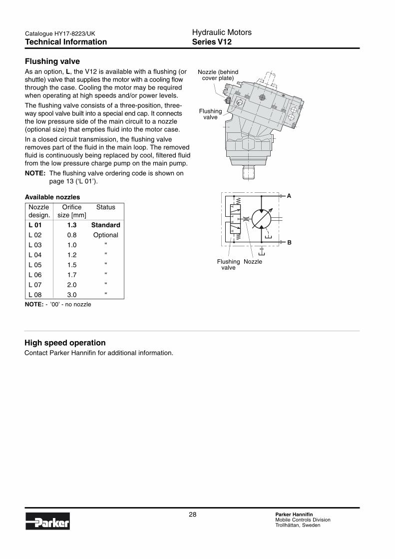
Flushing valveAs an option, L, the V12 is available with a flushing (orshuttle) valve that supplies the motor with a cooling flowthrough the case. Cooling the motor may be requiredwhen operating at high speeds and/or power levels.
The flushing valve consists of a three-position, three-way spool valve built into a special end cap. It connectsthe low pressure side of the main circuit to a nozzle(optional size) that empties fluid into the motor case.
In a closed circuit transmission, the flushing valveremoves part of the fluid in the main loop. The removedfluid is continuously being replaced by cool, filtered fluidfrom the low pressure charge pump on the main pump.
NOTE: The flushing valve ordering code is shown onpage 13 (‘L 01’).
Available nozzles
Nozzle Orifice Statusdesign. size [mm]
L 01 1.3 Standard
L 02 0.8 Optional
L 03 1.0 “
L 04 1.2 “
L 05 1.5 “
L 06 1.7 “
L 07 2.0 “
L 08 3.0 “NOTE: - ’00’ - no nozzle
Nozzle (behindcover plate)
Flushingvalve
Flushing Nozzlevalve
High speed operationContact Parker Hannifin for additional information.
Technical Information
29 Parker HannifinMobile Controls DivisionTrollhättan, Sweden
Hydraulic MotorsSeries V12
2
Catalogue HY17-8223/UK
A
B
S
A
B
A
B
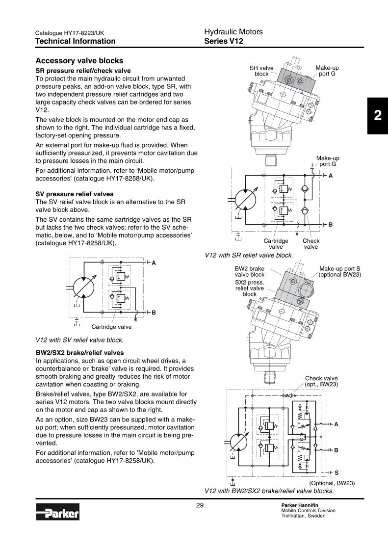
Accessory valve blocksSR pressure relief/check valveTo protect the main hydraulic circuit from unwantedpressure peaks, an add-on valve block, type SR, withtwo independent pressure relief cartridges and twolarge capacity check valves can be ordered for seriesV12.
The valve block is mounted on the motor end cap asshown to the right. The individual cartridge has a fixed,factory-set opening pressure.
An external port for make-up fluid is provided. Whensufficiently pressurized, it prevents motor cavitation dueto pressure losses in the main circuit.
For additional information, refer to ‘Mobile motor/pumpaccessories’ (catalogue HY17-8258/UK).
SV pressure relief valvesThe SV relief valve block is an alternative to the SRvalve block above.
The SV contains the same cartridge valves as the SRbut lacks the two check valves; refer to the SV sche-matic, below, and to ‘Mobile motor/pump accessories’(catalogue HY17-8258/UK).
BW2/SX2 brake/relief valvesIn applications, such as open circuit wheel drives, acounterbalance or ‘brake’ valve is required. It providessmooth braking and greatly reduces the risk of motorcavitation when coasting or braking.
Brake/relief valves, type BW2/SX2, are available forseries V12 motors. The two valve blocks mount directlyon the motor end cap as shown to the right.
As an option, size BW23 can be supplied with a make-up port; when sufficiently pressurized, motor cavitationdue to pressure losses in the main circuit is being pre-vented.
For additional information, refer to ’Mobile motor/pumpaccessories’ (catalogue HY17-8258/UK).
V12 with SV relief valve block.
V12 with SR relief valve block.
V12 with BW2/SX2 brake/relief valve blocks.
SR valveblock
Make-upport G
Make-upport G
Cartridge Checkvalve valve
BW2 brakevalve blockSX2 press.relief valve
block
Make-up port S(optional BW23)
Check valve(opt., BW23)
(Optional, BW23)
Cartridge valve
Technical Information
30 Parker HannifinMobile Controls DivisionTrollhättan, Sweden
Hydraulic MotorsSeries V12
Catalogue HY17-8223/UK
V12-80
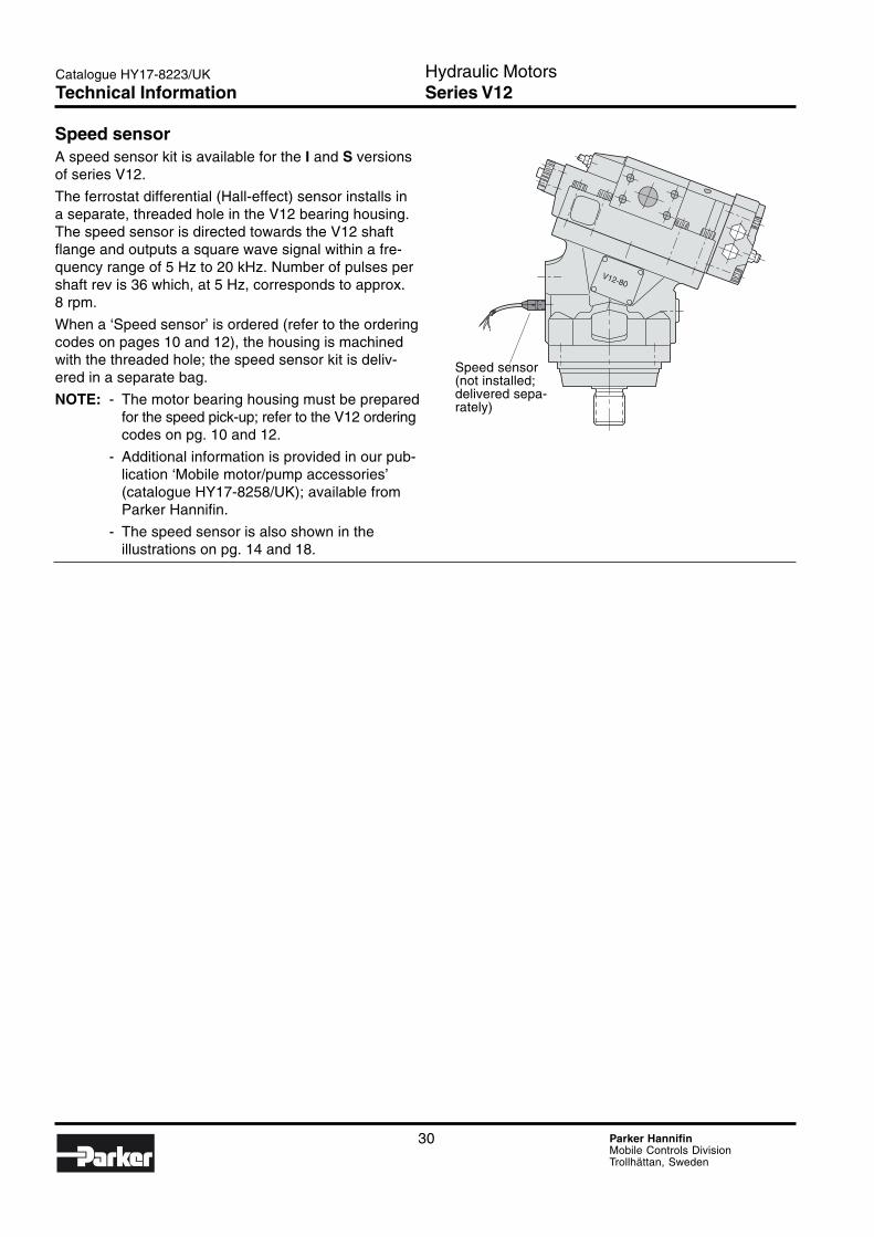
Speed sensorA speed sensor kit is available for the I and S versionsof series V12.
The ferrostat differential (Hall-effect) sensor installs ina separate, threaded hole in the V12 bearing housing.The speed sensor is directed towards the V12 shaftflange and outputs a square wave signal within a fre-quency range of 5 Hz to 20 kHz. Number of pulses pershaft rev is 36 which, at 5 Hz, corresponds to approx.8 rpm.
When a ‘Speed sensor’ is ordered (refer to the orderingcodes on pages 10 and 12), the housing is machinedwith the threaded hole; the speed sensor kit is deliv-ered in a separate bag.
NOTE: - The motor bearing housing must be preparedfor the speed pick-up; refer to the V12 orderingcodes on pg. 10 and 12.
- Additional information is provided in our pub-lication ‘Mobile motor/pump accessories’(catalogue HY17-8258/UK); available fromParker Hannifin.
- The speed sensor is also shown in theillustrations on pg. 14 and 18.
Speed sensor(not installed;delivered sepa-rately)
Technical Information
31 Parker HannifinMobile Controls DivisionTrollhättan, Sweden
Hydraulic MotorsSeries V14
3
Catalogue HY17-8223/UK
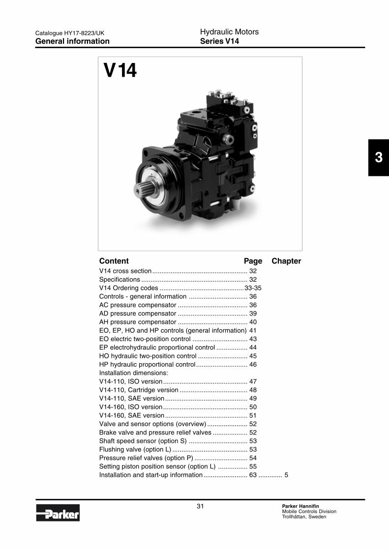
Content Page ChapterV14 cross section.................................................... 32Specifications .......................................................... 32V14 Ordering codes ..............................................33-35Controls - general information ................................ 36AC pressure compensator ...................................... 36AD pressure compensator ...................................... 39AH pressure compensator ...................................... 40EO, EP, HO and HP controls (general information) 41EO electric two-position control .............................. 43EP electrohydraulic proportional control ................. 44HO hydraulic two-position control ........................... 45HP hydraulic proportional control ............................ 46Installation dimensions:V14-110, ISO version.............................................. 47V14-110, Cartridge version ..................................... 48V14-110, SAE version ............................................. 49V14-160, ISO version.............................................. 50V14-160, SAE version ............................................. 51Valve and sensor options (overview) ...................... 52Brake valve and pressure relief valves ................... 52Shaft speed sensor (option S) ................................ 53Flushing valve (option L) ......................................... 53Pressure relief valves (option P) ............................. 54Setting piston position sensor (option L) ................ 55Installation and start-up information ........................ 63 ............. 5
V14
General information
32 Parker HannifinMobile Controls DivisionTrollhättan, Sweden
Hydraulic MotorsSeries V14
Catalogue HY17-8223/UK
5
6
7
8
9
10
11
12
13
14
15
16
17
1 2 3 4
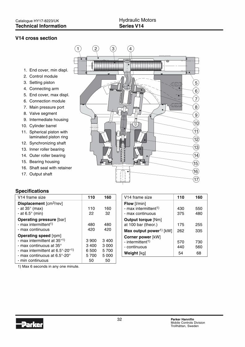
V14 frame size 110 160
Flow [l/min]- max intermittent1) 430 550- max continuous 375 480
Output torque [Nm]at 100 bar (theor.) 175 255
Max output power1) [kW] 262 335
Corner power [kW]- intermittent1) 570 730- continuous 440 560
Weight [kg] 54 68
SpecificationsV14 frame size 110 160
Displacement [cm3/rev]- at 35° (max) 110 160- at 6.5° (min) 22 32
Operating pressure [bar]- max intermittent1) 480 480- max continuous 420 420
Operating speed [rpm]- max intermittent at 35°1) 3 900 3 400- max continuous at 35° 3 400 3 000- max intermittent at 6.5°-20°1) 6 500 5 700- max continuous at 6.5°-20° 5 700 5 000- min continuous 50 501) Max 6 seconds in any one minute.
V14 cross section
1. End cover, min displ.
2. Control module
3. Setting piston
4. Connecting arm
5. End cover, max displ.
6. Connection module
7. Main pressure port
8. Valve segment
9. Intermediate housing
10. Cylinder barrel
11. Spherical piston withlaminated piston ring
12. Synchronizing shaft
13. Inner roller bearing
14. Outer roller bearing
15. Bearing housing
16. Shaft seal with retainer
17. Output shaft
Technical Information
33 Parker HannifinMobile Controls DivisionTrollhättan, Sweden
Hydraulic MotorsSeries V14
3
Catalogue HY17-8223/UK
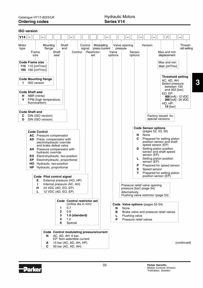
ISO version
V14 – – – – – – – / –
Motor Mounting Shaft Control Modulating Valve opening Version Thresh-type flange end signal press./current pressure old setting
Frame Shaft Control Restrictor Valve Sensor Max and minsize seal set options options displacement
Code Frame size110 110 [cm3/rev]160 160 [cm3/rev]
Code Mounting flangeI ISO version
Code Shaft sealH NBR (nitrile)V FPM (high temperature;
fluorocarbon)
Code Shaft endC DIN (ISO version)D DIN (ISO version)
Code ControlAC Pressure compensatorAD Press. compensator with
electrohydraulic overrideand brake defeat valve
AH Pressure compensator withhydraulic override
EO Electrohydraulic, two-positionEP Electrohydraulic, proportionalHO Hydraulic, two-positionHP Hydraulic, proportional
Code Pilot control signalE External pressure (HO, HP)I Internal pressure (AC, AH)H 24 VDC (AD, EO, EP)L 12 VDC (AD, EO, EP)
Code Control restrictor set(orifice dia in mm)
1 0.72 0.83 1.0 (standard)4 1.2X Special
Code Control modulating pressure/currentN AC, AD, AH: 0 bar;
EP: Non-selectible currentA 15 bar (AC, AD, AH, HP)C 50 bar (AC, AD, AH)
Max and mindispl. [cm3/rev]
Threshold settingAC, AD, AH:Select pressure
between 100and 350 [bar]
EO, EP:400 [mA] - 12 VDC200 [mA] - 24 VDC
HO, HP:10 [bar]
Factory issued forspecial versions
Code Sensor options(pages 52, 53, 55)
N NoneC Prepared for setting piston
position sensor and shaftspeed sensor (EP)
D Setting piston positionsensor and shaft speedsensor (EP)
L Setting piston positionsensor (EP)
P Prepared for speed sensorS Speed sensorT Prepared for setting piston
position sensor (EP)
Pressure relief valve openingpressure [bar] (page 54)Alternatively:Flushing valve restrictor (page 53)
Code Valve options (pages 52-54)N NoneB Brake valve and pressure relief valvesL Flushing valveP Pressure relief valves
(continued)
Ordering codes
34 Parker HannifinMobile Controls DivisionTrollhättan, Sweden
Hydraulic MotorsSeries V14
Catalogue HY17-8223/UK
Cartridge version
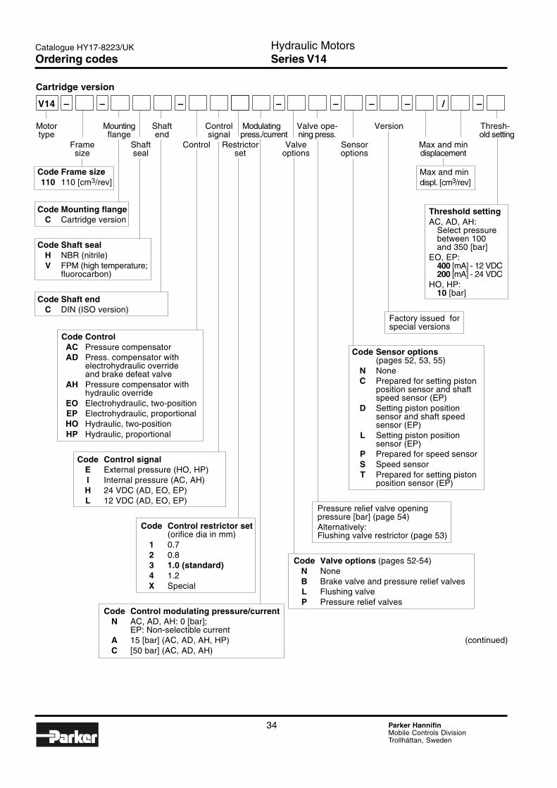
V14 – – – – – – – / –
Motor Mounting Shaft Control Modulating Valve ope- Version Thresh-type flange end signal press./current ning press. old setting
Frame Shaft Control Restrictor Valve Sensor Max and minsize seal set options options displacement
Code Frame size110 110 [cm3/rev]
Code Mounting flangeC Cartridge version
Code Shaft sealH NBR (nitrile)V FPM (high temperature;
fluorocarbon)
Code Shaft endC DIN (ISO version)
Code ControlAC Pressure compensatorAD Press. compensator with
electrohydraulic overrideand brake defeat valve
AH Pressure compensator withhydraulic override
EO Electrohydraulic, two-positionEP Electrohydraulic, proportionalHO Hydraulic, two-positionHP Hydraulic, proportional
Code Control signalE External pressure (HO, HP)I Internal pressure (AC, AH)H 24 VDC (AD, EO, EP)L 12 VDC (AD, EO, EP)
Code Control restrictor set(orifice dia in mm)
1 0.72 0.83 1.0 (standard)4 1.2X Special
Code Control modulating pressure/currentN AC, AD, AH: 0 [bar];
EP: Non-selectible currentA 15 [bar] (AC, AD, AH, HP)C [50 bar] (AC, AD, AH)
Max and mindispl. [cm3/rev]
Threshold settingAC, AD, AH:
Select pressurebetween 100and 350 [bar]
EO, EP:400 [mA] - 12 VDC200 [mA] - 24 VDC
HO, HP:10 [bar]
Factory issued forspecial versions
Code Sensor options(pages 52, 53, 55)
N NoneC Prepared for setting piston
position sensor and shaftspeed sensor (EP)
D Setting piston positionsensor and shaft speedsensor (EP)
L Setting piston positionsensor (EP)
P Prepared for speed sensorS Speed sensorT Prepared for setting piston
position sensor (EP)
Pressure relief valve openingpressure [bar] (page 54)Alternatively:Flushing valve restrictor (page 53)
Code Valve options (pages 52-54)N NoneB Brake valve and pressure relief valvesL Flushing valveP Pressure relief valves
(continued)
Ordering codes

35 Parker HannifinMobile Controls DivisionTrollhättan, Sweden
Hydraulic MotorsSeries V14
3
Catalogue HY17-8223/UK
SAE version
V14 – – – – – – – / –
Motor Mounting Shaft Control Modulating Valve ope- Version Thresh-type flange end signal press./current ning press. old setting
Frame Shaft Control Restrictor Valve Sensor Max and minsize seal set options options displacement
Code Frame size110 110 [cm3/rev]160 160 [cm3/rev]
Code Mounting flangeS SAE version
Code Shaft sealH NBR (nitrile)V FPM (high temperature;
fluorocarbon)
Code Shaft endS SAE (SAE version)
Code ControlAC Pressure compensatorAD Press. compensator with
electrohydraulic overrideand brake defeat valve
AH Pressure compensator withhydraulic override
EO Electrohydraulic, two-positionEP Electrohydraulic, proportionalHO Hydraulic, two-positionHP Hydraulic, proportional
Code Control signalE External pressure (HO, HP)I Internal pressure (AC, AH)H 24 VDC (AD, EO, EP)L 12 VDC (AD, EO, EP)
Code Control restrictor set(orifice dia in mm)
1 0.72 0.83 1.0 (standard)4 1.2X Special
Code Control modulating pressure/currentN AC, AD, AH: 0 bar;
EP: Non-selectible currentA 15 bar (AC, AD, AH, HP)C 50 bar (AC, AD, AH)
Max and mindispl. [cm3/rev]
Threshold settingAC, AD. AH:
Select pressurebetween 100and 350 [bar]
EO, EP:400 [mA] - 12 VDC200 [mA] - 24 VDC
HO, HP:10 [bar]
Factory issued forspecial versions
Code Sensor options(pages 52, 53, 55)
N NoneC Prepared for setting piston
position sensor and shaftspeed sensor (EP)
D Setting piston positionsensor and shaft speedsensor (EP)
L Setting piston positionsensor (EP)
P Prepared for speed sensorS Speed sensorT Prepared for setting piston
position sensor (EP)
Pressure relief valve openingpressure [bar] (page 54)Alternatively:Flushing valve restrictor (page 53)
Code Valve options (pages 52-54)N NoneB Brake valve and pressure relief valvesL Flushing valveP Pressure relief valves
Ordering codes
36 Parker HannifinMobile Controls DivisionTrollhättan, Sweden
Hydraulic MotorsSeries V14
Catalogue HY17-8223/UK
1 2 3 4 5 6 7 8
9 10 11 12 13 14 15 16
E
Servo supply pressure is obtained from the pressu-rized, main port through the corresponding, built-inshuttle valve.
The response time (i.e. from max-to-min or from min-to-max displacement) is determined by restrictor nozzlesin the servo valve supply and return lines; refer to theschematics.
The modulating pressure/current, ∆p/∆I values arevalid for motors that are not diplacement limited.
Controls - general information
The following V14 controls satisfy most applicationrequirements:
• AC, AD and AH (automatic pressure compensators)
• EO and HO (two-position controls)
• EP and HP (proportional controls)
All controls utilize a servo piston that connects to thevalve segment (refer to the illustration on page 32).
The built-in four-way servo valve determines the posi-tion of the servo piston and, in turn, the displacement.
The displacement angle (between output shaft andcylinder barrel) ranges from 35° (max) to 6.5° (min).
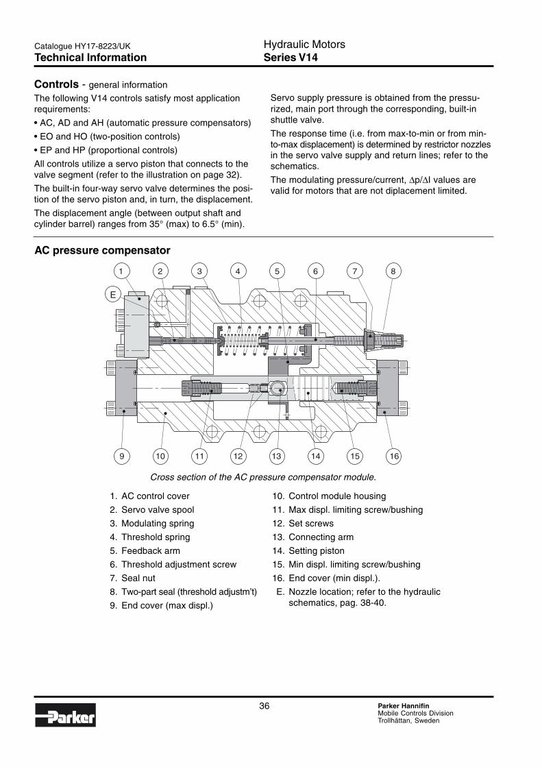
AC pressure compensator
1. AC control cover
2. Servo valve spool
3. Modulating spring
4. Threshold spring
5. Feedback arm
6. Threshold adjustment screw
7. Seal nut
8. Two-part seal (threshold adjustm’t)
9. End cover (max displ.)
10. Control module housing
11. Max displ. limiting screw/bushing
12. Set screws
13. Connecting arm
14. Setting piston
15. Min displ. limiting screw/bushing
16. End cover (min displ.).
E. Nozzle location; refer to the hydraulicschematics, pag. 38-40.
Cross section of the AC pressure compensator module.
Technical Information
37 Parker HannifinMobile Controls DivisionTrollhättan, Sweden
Hydraulic MotorsSeries V14
3
Catalogue HY17-8223/UK
A
BE D
C
A
B
ED
C
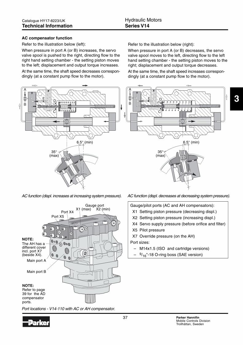
Gauge/pilot ports (AC and AH compensators):
X1 Setting piston pressure (decreasing displ.)
X2 Setting piston pressure (increasing displ.)
X4 Servo supply pressure (before orifice and filter)
X5 Pilot pressure
X7 Override pressure (on the AH)
Port sizes:
– M14x1.5 (ISO and cartridge versions)
– 9/16"-18 O-ring boss (SAE version)
AC function (displ. decreases at decreasing system pressure).AC function (displ. increases at increasing system pressure).
AC compensator function
Refer to the illustration below (left):
When pressure in port A (or B) increases, the servovalve spool is pushed to the right, directing flow to theright hand setting chamber - the setting piston movesto the left; displacement and output torque increases.
At the same time, the shaft speed decreases correspon-dingly (at a constant pump flow to the motor).
Refer to the illustration below (right):
When pressure in port A (or B) decreases, the servovalve spool moves to the left, directing flow to the lefthand setting chamber - the setting piston moves to theright; displacement and output torque decreases.
At the same time, the shaft speed increases correspon-dingly (at a constant pump flow to the motor).
Port locations - V14-110 with AC or AH compensator.
35°(max)
6.5° (min)
35°(max)
6.5° (min)
Main port A
Main port B
Gauge portX1 (max) X2 (min)
Port X4Port X5
NOTE:Refer to page39 for the ADcompensatorports.
NOTE:The AH has adifferent coverincl. port X7(beside X4).
Technical Information
38 Parker HannifinMobile Controls DivisionTrollhättan, Sweden
Hydraulic MotorsSeries V14
Catalogue HY17-8223/UK
A B
X2X1
X5
X4
E
C D
Max
Min
Max
Min
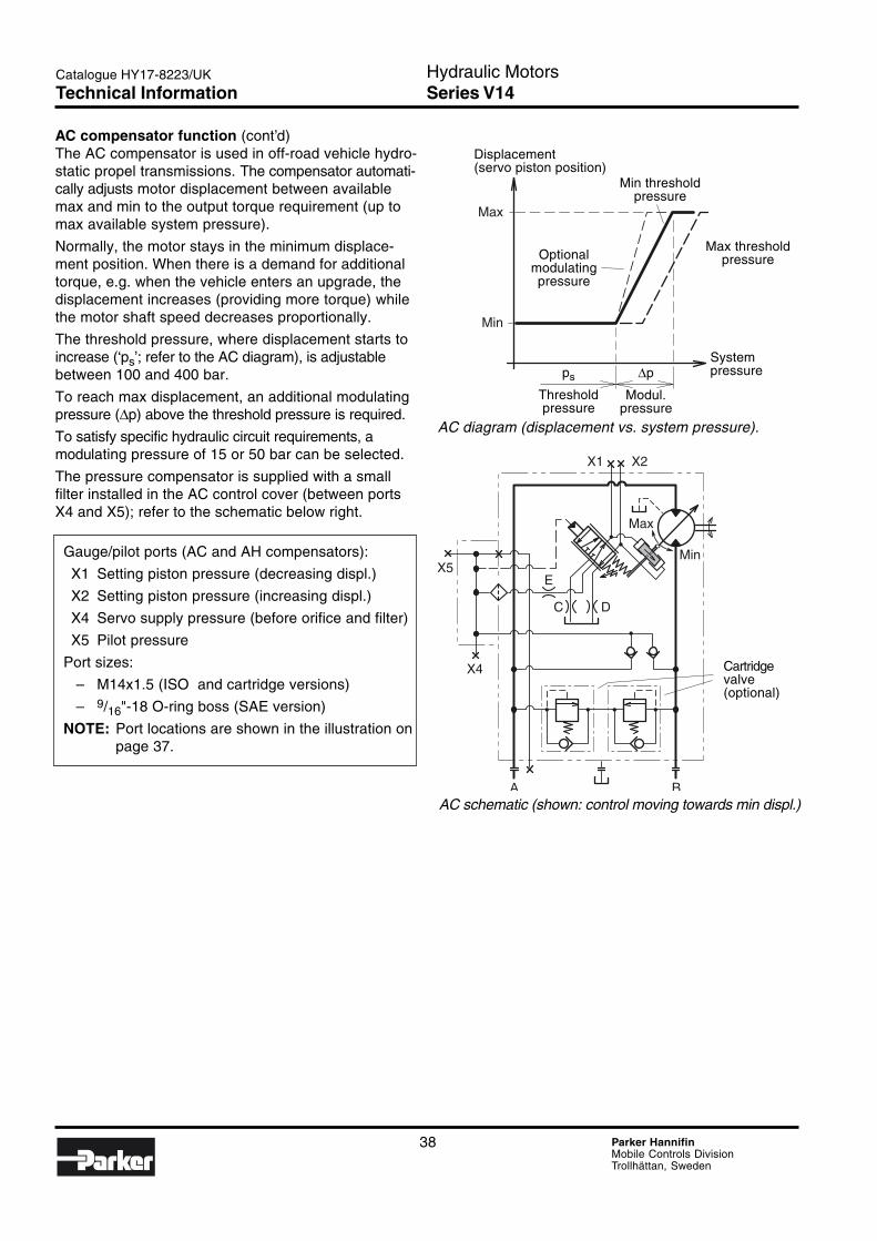
AC compensator function (cont’d)The AC compensator is used in off-road vehicle hydro-static propel transmissions. The compensator automati-cally adjusts motor displacement between availablemax and min to the output torque requirement (up tomax available system pressure).
Normally, the motor stays in the minimum displace-ment position. When there is a demand for additionaltorque, e.g. when the vehicle enters an upgrade, thedisplacement increases (providing more torque) whilethe motor shaft speed decreases proportionally.
The threshold pressure, where displacement starts toincrease (‘ps’; refer to the AC diagram), is adjustablebetween 100 and 400 bar.
To reach max displacement, an additional modulatingpressure (∆p) above the threshold pressure is required.
To satisfy specific hydraulic circuit requirements, amodulating pressure of 15 or 50 bar can be selected.
The pressure compensator is supplied with a smallfilter installed in the AC control cover (between portsX4 and X5); refer to the schematic below right.
Gauge/pilot ports (AC and AH compensators):
X1 Setting piston pressure (decreasing displ.)
X2 Setting piston pressure (increasing displ.)
X4 Servo supply pressure (before orifice and filter)
X5 Pilot pressure
Port sizes:
– M14x1.5 (ISO and cartridge versions)
– 9/16"-18 O-ring boss (SAE version)
NOTE: Port locations are shown in the illustration onpage 37.
AC schematic (shown: control moving towards min displ.)
Displacement(servo piston position)
Optionalmodulatingpressure
Min thresholdpressure
Max thresholdpressure
ps
Thresholdpressure
∆p
Modul.pressure
Systempressure
Cartridgevalve(optional)
AC diagram (displacement vs. system pressure).
Technical Information
39 Parker HannifinMobile Controls DivisionTrollhättan, Sweden
Hydraulic MotorsSeries V14
3
Catalogue HY17-8223/UK
A B
X2X1X10
X9
E
C D
Max
Min
Max
Min
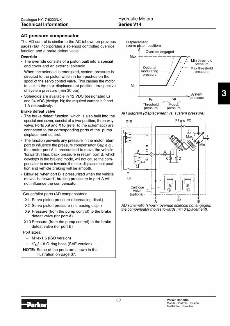
AD pressure compensatorThe AD control is similar to the AC (shown on previouspages) but incorporates a solenoid controlled overridefunction and a brake defeat valve.
Override- The override consists of a piston built into a special
end cover and an external solenoid.
- When the solenoid is energized, system pressure isdirected to the piston which in turn pushes on thespool of the servo control valve. This causes the motorto lock in the max displacement position, irrespectiveof system pressure (min 30 bar).
- Solenoids are available in 12 VDC (designated L)and 24 VDC (design. H); the required current is 2 and1 A respectively.
Brake defeat valve- The brake defeat function, which is also built into the
special end cover, consist of a two-position, three-wayvalve. Ports X9 and X10 (refer to the schematic) areconnected to the corresponding ports of the pumpdisplacement control.
- The function prevents any pressure in the motor returnport to influence the pressure compensator. Say, e.g.,that motor port A is pressurized to move the vehicle‘forward’. Thus, back pressure in return port B, whichdevelops in the braking mode, will not cause the com-pensator to move towards the max displacement posi-tion and vehicle braking will be smooth.
- Likewise, when port B is pressurized when the vehiclemoves ‘backward’, braking presssure in port A willnot influence the compensator.
Gauge/pilot ports (AD compensator):
X1 Servo piston pressure (decreasing displ.)
X2 Servo piston pressure (increasing displ.)
X9 Pressure (from the pump control) to the brakedefeat valve (for port A)
X10 Pressure (from the pump control) to the brakedefeat valve (for port B)
Port sizes:
– M14x1.5 (ISO version)
– 9/16"-18 O-ring boss (SAE version)
NOTE: Some of the ports are shown in theillustration on page 37.
Displacement(servo piston position)
Optionalmodulatingpressure
Override engaged
Min thresholdpressure
Max thresholdpressure
ps
Thresholdpressure
∆p
Modul.pressure
Systempressure
AH diagram (displacement vs. system pressure).
AD schematic (shown: override solenoid not engaged;the compensator moves towards min displacement).
Cartridgevalve
(optional)
Technical Information
40 Parker HannifinMobile Controls DivisionTrollhättan, Sweden
Hydraulic MotorsSeries V14
Catalogue HY17-8223/UK
A B
X2X1
X5
X7
X4
E
C D
Max
Min
Max
Min
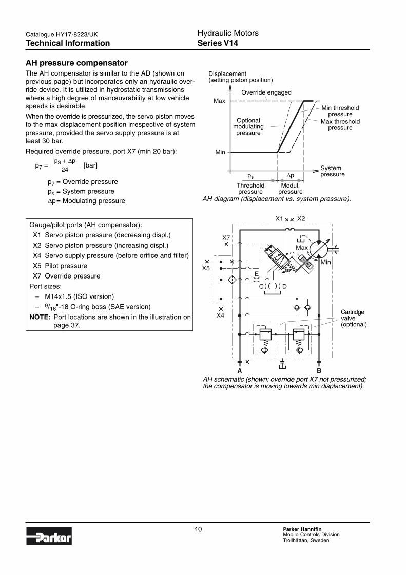
AH pressure compensatorThe AH compensator is similar to the AD (shown onprevious page) but incorporates only an hydraulic over-ride device. It is utilized in hydrostatic transmissionswhere a high degree of manœuvrability at low vehiclespeeds is desirable.
When the override is pressurized, the servo piston movesto the max displacement position irrespective of systempressure, provided the servo supply pressure is atleast 30 bar.
Required override pressure, port X7 (min 20 bar):
p7 = [bar]
p7 = Override pressureps = System pressure∆p= Modulating pressure
Gauge/pilot ports (AH compensator):
X1 Servo piston pressure (decreasing displ.)
X2 Servo piston pressure (increasing displ.)
X4 Servo supply pressure (before orifice and filter)
X5 Pilot pressure
X7 Override pressure
Port sizes:
– M14x1.5 (ISO version)
– 9/16"-18 O-ring boss (SAE version)
NOTE: Port locations are shown in the illustration onpage 37.
Displacement(setting piston position)
Optionalmodulatingpressure
Override engaged
Min thresholdpressure
Max thresholdpressure
ps
Thresholdpressure
∆p
Modul.pressure
Systempressure
AH diagram (displacement vs. system pressure).
AH schematic (shown: override port X7 not pressurized;the compensator is moving towards min displacement).
Cartridgevalve(optional)
pS + ∆p
24
Technical Information
41 Parker HannifinMobile Controls DivisionTrollhättan, Sweden
Hydraulic MotorsSeries V14
3
Catalogue HY17-8223/UK
1 2 3 4 5 6 7 8
9 10 11 12 13 14 15 16
E
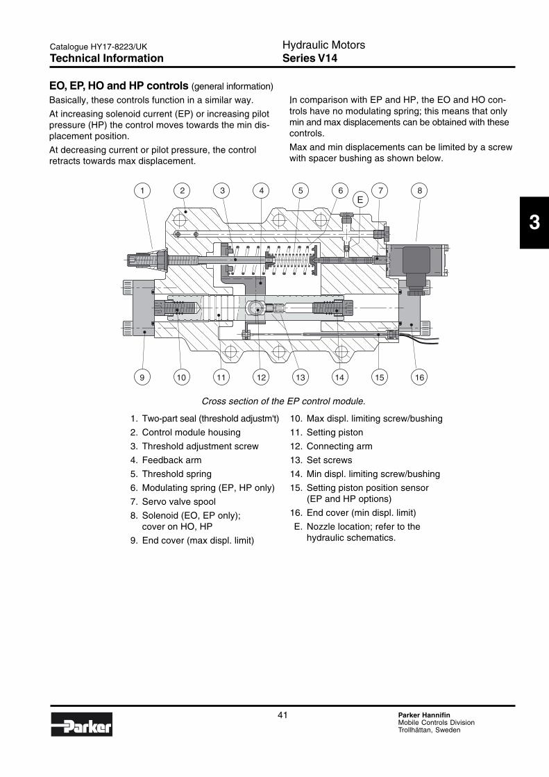
Cross section of the EP control module.
1. Two-part seal (threshold adjustm't)
2. Control module housing
3. Threshold adjustment screw
4. Feedback arm
5. Threshold spring
6. Modulating spring (EP, HP only)
7. Servo valve spool
8. Solenoid (EO, EP only);cover on HO, HP
9. End cover (max displ. limit)
EO, EP, HO and HP controls (general information)
Basically, these controls function in a similar way.
At increasing solenoid current (EP) or increasing pilotpressure (HP) the control moves towards the min dis-placement position.
At decreasing current or pilot pressure, the controlretracts towards max displacement.
.In comparison with EP and HP, the EO and HO con-trols have no modulating spring; this means that onlymin and max displacements can be obtained with thesecontrols.
Max and min displacements can be limited by a screwwith spacer bushing as shown below.
10. Max displ. limiting screw/bushing
11. Setting piston
12. Connecting arm
13. Set screws
14. Min displ. limiting screw/bushing
15. Setting piston position sensor(EP and HP options)
16. End cover (min displ. limit)
E. Nozzle location; refer to thehydraulic schematics.
Technical Information
42 Parker HannifinMobile Controls DivisionTrollhättan, Sweden
Hydraulic MotorsSeries V14
Catalogue HY17-8223/UK
ED
C
A
BED
C
A
B
EP control function (displ. decrease at increasing current). HP control function (displ. increase at decreasing pilot press.).
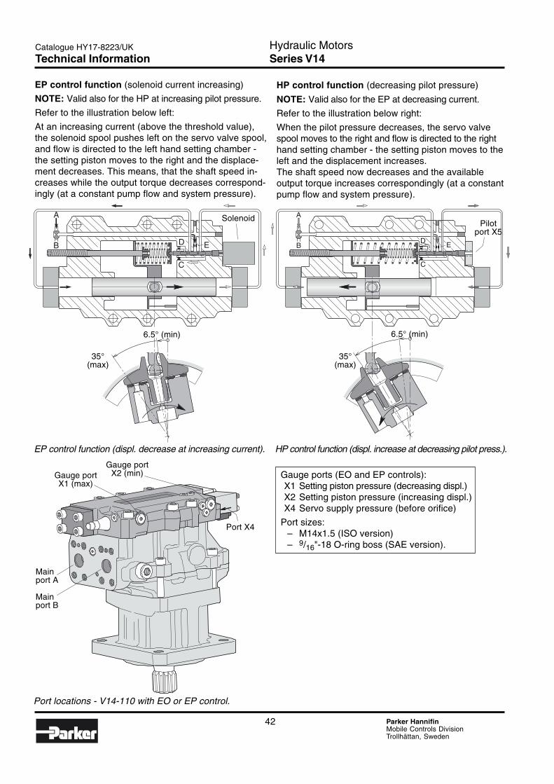
EP control function (solenoid current increasing)
NOTE: Valid also for the HP at increasing pilot pressure.
Refer to the illustration below left:
At an increasing current (above the threshold value),the solenoid spool pushes left on the servo valve spool,and flow is directed to the left hand setting chamber -the setting piston moves to the right and the displace-ment decreases. This means, that the shaft speed in-creases while the output torque decreases correspond-ingly (at a constant pump flow and system pressure).
HP control function (decreasing pilot pressure)
NOTE: Valid also for the EP at decreasing current.
Refer to the illustration below right:
When the pilot pressure decreases, the servo valvespool moves to the right and flow is directed to the righthand setting chamber - the setting piston moves to theleft and the displacement increases.The shaft speed now decreases and the availableoutput torque increases correspondingly (at a constantpump flow and system pressure).
35°(max)
6.5° (min)
35°(max)
6.5° (min)
SolenoidPilot
port X5
Gauge ports (EO and EP controls):X1 Setting piston pressure (decreasing displ.)X2 Setting piston pressure (increasing displ.)X4 Servo supply pressure (before orifice)
Port sizes:– M14x1.5 (ISO version)– 9/16"-18 O-ring boss (SAE version).
Port locations - V14-110 with EO or EP control.
Mainport A
Mainport B
Gauge portX1 (max)
Gauge portX2 (min)
Port X4
Technical Information
43 Parker HannifinMobile Controls DivisionTrollhättan, Sweden
Hydraulic MotorsSeries V14
3
Catalogue HY17-8223/UK
A B
X2 X1
X4EC D
Min
Max
Max
Min
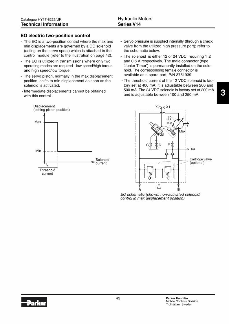
EO electric two-position control- The EO is a two-position control where the max and
min displacements are governed by a DC solenoid(acting on the servo spool) which is attached to thecontrol module (refer to the illustration on page 42).
- The EO is utilized in transmissions where only twooperating modes are required - low speed/high torqueand high speed/low torque.
- The servo piston, normally in the max displacementposition, shifts to min displacement as soon as thesolenoid is activated.
- Intermediate displacements cannot be obtainedwith this control.
- Servo pressure is supplied internally (through a checkvalve from the utilized high pressure port); refer tothe schematic below.
- The solenoid is either 12 or 24 VDC, requiring 1 .2and 0.6 A respectively. The male connector (type’Junior Timer’) is permanently installed on the sole-noid. The corresponding female connector isavailable as a spare part, P/N 3781939.
- The threshold current of the 12 VDC solenoid is fac-tory set at 400 mA; it is adjustable between 200 and500 mA. The 24 VDC solenoid is factory set at 200 mAand is adjustable between 100 and 250 mA.
EO schematic (shown: non-activated solenoid;control in max displacement position).
Displacement(setting piston position)
IsThreshold
current
Solenoidcurrent
Cartridge valve(optional)
Technical Information
44 Parker HannifinMobile Controls DivisionTrollhättan, Sweden
Hydraulic MotorsSeries V14
Catalogue HY17-8223/UK
A B
X2 X1
X4EC D
Min
Max
Max
Min
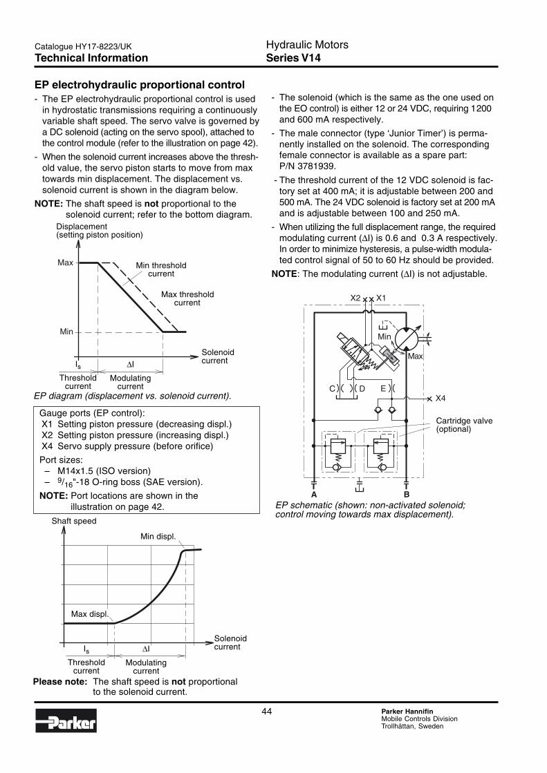
EP electrohydraulic proportional control- The EP electrohydraulic proportional control is used
in hydrostatic transmissions requiring a continuouslyvariable shaft speed. The servo valve is governed bya DC solenoid (acting on the servo spool), attached tothe control module (refer to the illustration on page 42).
- When the solenoid current increases above the thresh-old value, the servo piston starts to move from maxtowards min displacement. The displacement vs.solenoid current is shown in the diagram below.
NOTE: The shaft speed is not proportional to thesolenoid current; refer to the bottom diagram.
EP diagram (displacement vs. solenoid current).
EP schematic (shown: non-activated solenoid;control moving towards max displacement).
Please note: The shaft speed is not proportionalto the solenoid current.
Gauge ports (EP control):X1 Setting piston pressure (decreasing displ.)X2 Setting piston pressure (increasing displ.)X4 Servo supply pressure (before orifice)
Port sizes:– M14x1.5 (ISO version)– 9/16"-18 O-ring boss (SAE version).
NOTE: Port locations are shown in theillustration on page 42.
- The solenoid (which is the same as the one used onthe EO control) is either 12 or 24 VDC, requiring 1200and 600 mA respectively.
- The male connector (type ‘Junior Timer’) is perma-nently installed on the solenoid. The correspondingfemale connector is available as a spare part:P/N 3781939.
- The threshold current of the 12 VDC solenoid is fac-tory set at 400 mA; it is adjustable between 200 and500 mA. The 24 VDC solenoid is factory set at 200 mAand is adjustable between 100 and 250 mA.
- When utilizing the full displacement range, the requiredmodulating current (∆I) is 0.6 and 0.3 A respectively.In order to minimize hysteresis, a pulse-width modula-ted control signal of 50 to 60 Hz should be provided.
NOTE: The modulating current (∆I) is not adjustable.
Displacement(setting piston position)
Min thresholdcurrent
Max thresholdcurrent
SolenoidcurrentIs
Thresholdcurrent
∆I
Modulatingcurrent
Shaft speed
Max displ.
Min displ.
IsThreshold
current
∆I
Modulatingcurrent
Solenoidcurrent
Cartridge valve(optional)
Technical Information
45 Parker HannifinMobile Controls DivisionTrollhättan, Sweden
Hydraulic MotorsSeries V14
3
Catalogue HY17-8223/UK
X5
A B
X2 X1
X4EC D
Min
Max
Max 100 bar
Max
Min
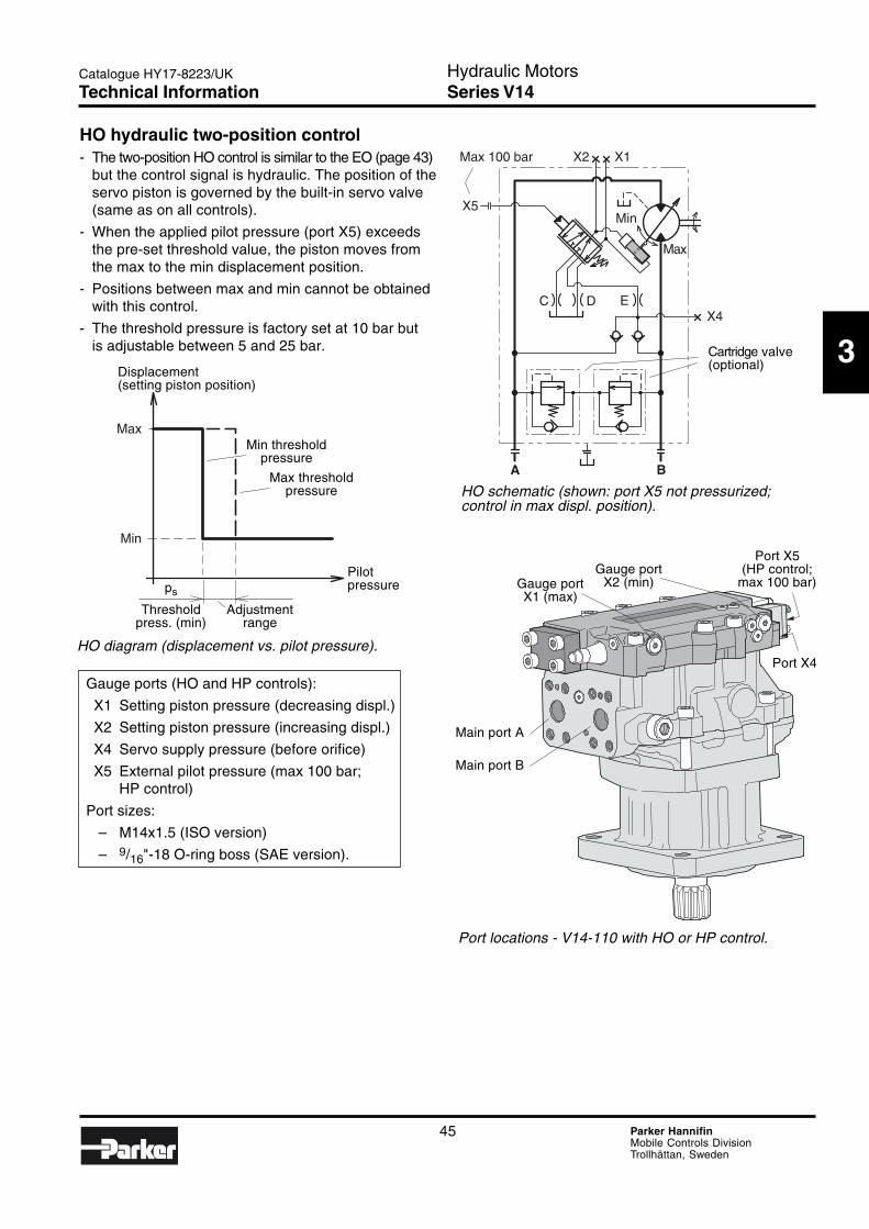
Gauge ports (HO and HP controls):
X1 Setting piston pressure (decreasing displ.)
X2 Setting piston pressure (increasing displ.)
X4 Servo supply pressure (before orifice)
X5 External pilot pressure (max 100 bar;HP control)
Port sizes:
– M14x1.5 (ISO version)
– 9/16"-18 O-ring boss (SAE version).
HO diagram (displacement vs. pilot pressure).
HO schematic (shown: port X5 not pressurized;control in max displ. position).
HO hydraulic two-position control- The two-position HO control is similar to the EO (page 43)
but the control signal is hydraulic. The position of theservo piston is governed by the built-in servo valve(same as on all controls).
- When the applied pilot pressure (port X5) exceedsthe pre-set threshold value, the piston moves fromthe max to the min displacement position.
- Positions between max and min cannot be obtainedwith this control.
- The threshold pressure is factory set at 10 bar butis adjustable between 5 and 25 bar.
Port locations - V14-110 with HO or HP control.
Port X5(HP control;
max 100 bar)Gauge port
X2 (min)Gauge portX1 (max)
Main port A
Main port B
Port X4
Displacement(setting piston position)
Min thresholdpressure
Max thresholdpressure
ps
Threshold Adjustmentpress. (min) range
Pilotpressure
Cartridge valve(optional)
Technical Information
46 Parker HannifinMobile Controls DivisionTrollhättan, Sweden
Hydraulic MotorsSeries V14
Catalogue HY17-8223/UK
A B
X2 X1
X4
EC D
Min
Max
X5
Max 100 bar
Max
Min
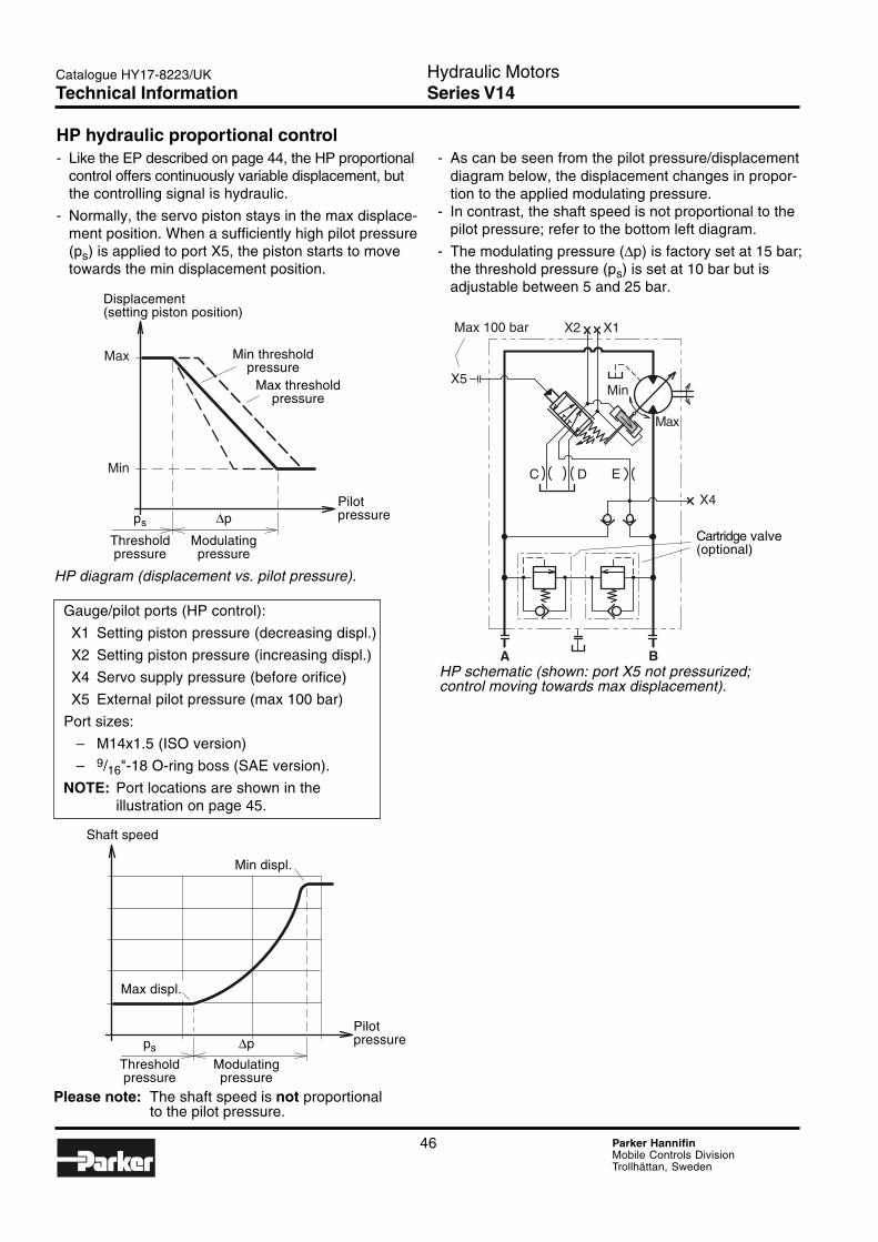
Please note: The shaft speed is not proportionalto the pilot pressure.
Gauge/pilot ports (HP control):
X1 Setting piston pressure (decreasing displ.)
X2 Setting piston pressure (increasing displ.)
X4 Servo supply pressure (before orifice)
X5 External pilot pressure (max 100 bar)
Port sizes:
– M14x1.5 (ISO version)
– 9/16"-18 O-ring boss (SAE version).
NOTE: Port locations are shown in theillustration on page 45.
HP hydraulic proportional control- Like the EP described on page 44, the HP proportional
control offers continuously variable displacement, butthe controlling signal is hydraulic.
- Normally, the servo piston stays in the max displace-ment position. When a sufficiently high pilot pressure(ps) is applied to port X5, the piston starts to movetowards the min displacement position.
- As can be seen from the pilot pressure/displacementdiagram below, the displacement changes in propor-tion to the applied modulating pressure.
- In contrast, the shaft speed is not proportional to thepilot pressure; refer to the bottom left diagram.
- The modulating pressure (∆p) is factory set at 15 bar;the threshold pressure (ps) is set at 10 bar but isadjustable between 5 and 25 bar.
HP diagram (displacement vs. pilot pressure).
HP schematic (shown: port X5 not pressurized;control moving towards max displacement).
Displacement(setting piston position)
Min thresholdpressure
Max thresholdpressure
ps ∆p
Threshold Modulatingpressure pressure
Pilotpressure
Shaft speed
Max displ.
Min displ.
ps ∆p
Threshold Modulatingpressure pressure
Pilotpressure
Cartridge valve(optional)
Technical Information
47 Parker HannifinMobile Controls DivisionTrollhättan, Sweden
Hydraulic MotorsSeries V14
3
Catalogue HY17-8223/UK
208 134
23
162
180
87
75
φ 160 (tol. h8)
180
φ 18 (x4)(φ 200)
260
152155
φ 25 (x2)
45
Spline type C1) (DIN 5480)
V14-110 W40x2x18x9g
Spline type D1) (DIN 5480)
V14-110 W45x2x21x9g1) ‘30° involute spline, side fit’
Ports V14-110
Main ports 25 [1"]
Drain ports M22x1.5Main ports: ISO 6162, 41.5 MPa, type II
V14-110, ISO version
Shown: V14-110-ISO with AC compensator
Port B
57.2
Alternativedrain portM22x1.5(plugged;opposite)
141.4
141.4
Drain portM22x1,5
(opposite)
Cartridge valve(optional)
Speed sensor(optional)
I mountingflange
C or Dspline shaft C:φ 39.6; D:φ 44.6; tol. h11
85.5
Port A
66.5
27.8
* Measurement valid for spline type C.Corresponding measurement forspline type D is 5 mm longer.
Installation dimensions

48 Parker HannifinMobile Controls DivisionTrollhättan, Sweden
Hydraulic MotorsSeries V14
Catalogue HY17-8223/UK
φ 22 (x2)
250
φ 286
207 134
23
162 117
174
87
75
205
7274
97
20
15
45
168
100
M12x24(x8)
V14-110, Cartridge version
Spline type C* (DIN 5480)
V14-110 W40x2x18x9g
* ‘30° involute spline, side fit’.
Ports V14-110
Main ports 25 [1"]
Drain ports M22x1.5
Main ports: ISO 6162, 41.5 MPa, type II
C mountingflange
27.8
Drain port(opposite)
Port B
57.2
C splineshaft
Alternativedrain port(opposite;plugged)
φ 39.6 (tol. h11, +0/-0.16)
φ 200 (tol. h8, +0/-0.072)
Port A
Cartridge valve(optional)
Shown: V14-110-SAE with HO/HP control
O-ring(192x4)
Installation dimensions
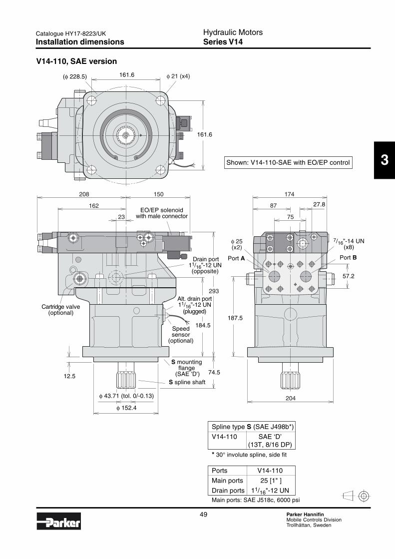
49 Parker HannifinMobile Controls DivisionTrollhättan, Sweden
Hydraulic MotorsSeries V14
3
Catalogue HY17-8223/UK
φ 21 (x4)
208 150
23
162
174
87
75
204
293
φ 25(x2)
Spline type S (SAE J498b*)
V14-110 SAE ‘D’(13T, 8/16 DP)
* 30° involute spline, side fit
Ports V14-110
Main ports 25 [1" ]
Drain ports 11/16"-12 UNMain ports: SAE J518c, 6000 psi
V14-110, SAE version
Shown: V14-110-SAE with EO/EP control
Alt. drain port11/16”-12 UN
(plugged)
7/16”-14 UN(x8)
Port B
161.6
161.6
(φ 228.5)
EO/EP solenoidwith male connector
Drain port11/16”-12 UN(opposite)
Speedsensor
(optional)
12.5
φ 43.71 (tol. 0/-0.13)
φ 152.4
S mountingflange
(SAE 'D')S spline shaft
74.5
184.5187.5
Port A
57.2
27.8
Cartridge valve(optional)
Installation dimensions
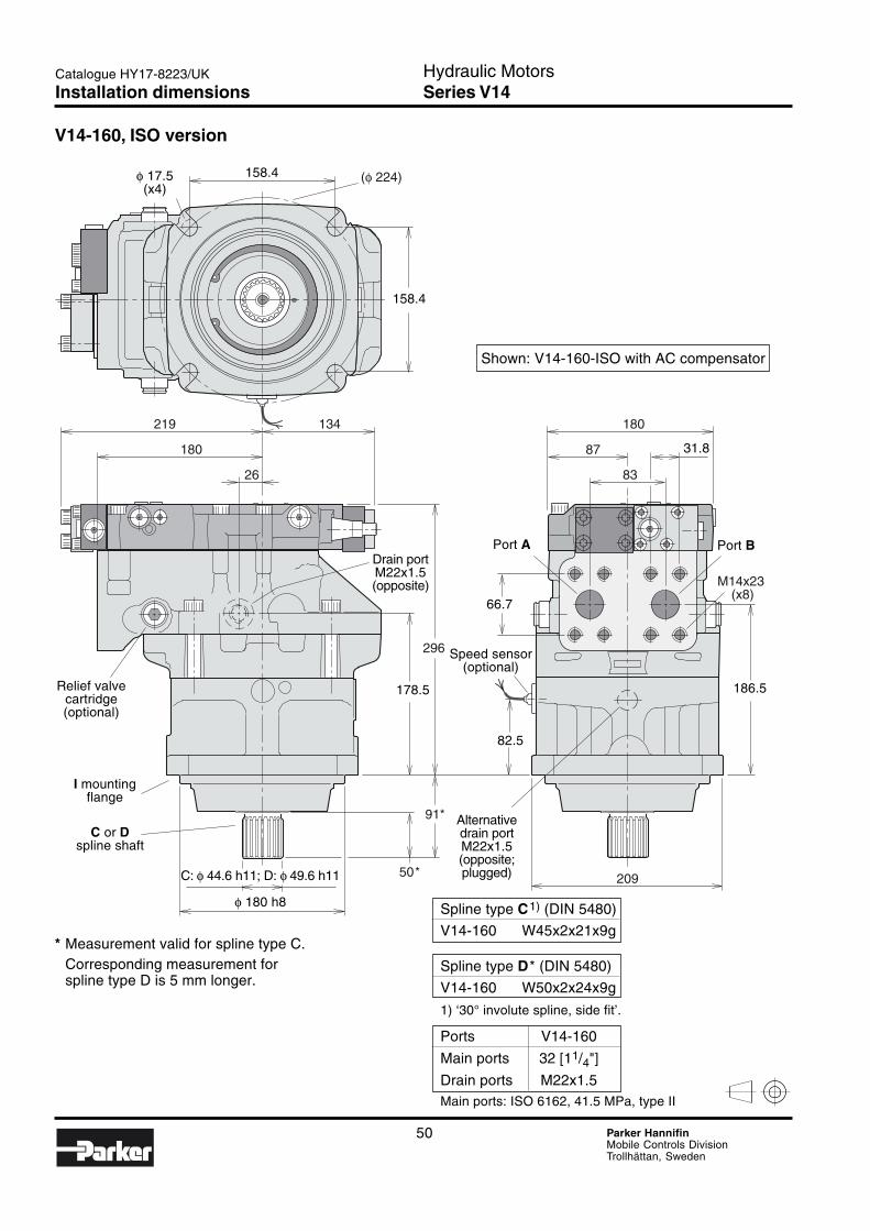
50 Parker HannifinMobile Controls DivisionTrollhättan, Sweden
Hydraulic MotorsSeries V14
Catalogue HY17-8223/UK
(φ 224)
219 134
26
180
296
91*
50*
180
87
83
209
M14x23 (x8)
V14-160, ISO version
Relief valvecartridge(optional)
I mountingflange
C or Dspline shaft
158.4φ 17.5(x4)
158.4
C: φ 44.6 h11; D: φ 49.6 h11
φ 180 h8
82.5
178.5
Drain portM22x1.5(opposite)
66.7
Port A Port B
186.5
31.8
Spline type C1) (DIN 5480)
V14-160 W45x2x21x9g
Spline type D* (DIN 5480)
V14-160 W50x2x24x9g
1) ‘30° involute spline, side fit’.
Ports V14-160
Main ports 32 [11/4"]
Drain ports M22x1.5Main ports: ISO 6162, 41.5 MPa, type II
Alternativedrain portM22x1.5(opposite;plugged)
Shown: V14-160-ISO with AC compensator
* Measurement valid for spline type C.Corresponding measurement forspline type D is 5 mm longer.
Speed sensor(optional)
Installation dimensions

51 Parker HannifinMobile Controls DivisionTrollhättan, Sweden
Hydraulic MotorsSeries V14
3
Catalogue HY17-8223/UK
φ 21 (x4)
219 139
26
180
328
75
204
115
211
25
174
87
83
200
219
V14-160, SAE version
Spline type S (SAE J498b*)
V14-160 SAE ‘D’(13T, 8/16 DP)
* ‘30° involute spline, side fit’.
Ports V14-160
Main ports 32 [11/4" ]
Drain ports 11/16"-12 UNMain ports: SAE J518c, 6000 psi
1/2”-13 UNC(x8)
161.6(φ 228.5)
EO/EP solenoidwith male connector
66.7
Port Aφ 32
Port Bφ 32
Alt. drain port11/16”-12 UN
(plugged)
Drain port11/16”-12 UN(opposite)
12.5S mounting
flange
(SAE 'D')
S spline shaft
φ 43.71 (0/-0.13)
φ 152.4 (0/-0.05)
31.8
161.6
Cartridge valve(optional)
Shown: V14-160-SAE with EO/EP control
Speed sensor(optional)
Installation dimensions
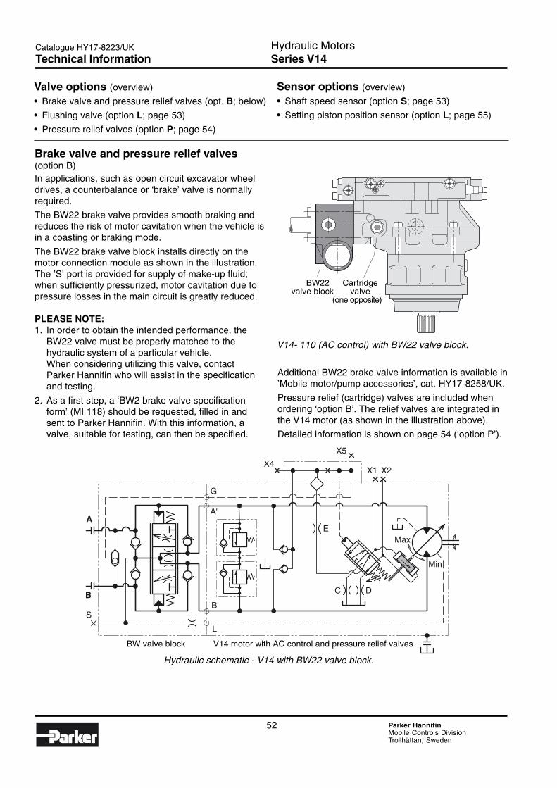
52 Parker HannifinMobile Controls DivisionTrollhättan, Sweden
Hydraulic MotorsSeries V14
Catalogue HY17-8223/UK
A
S
L
G
A'
B'B
X2X1
X5
X4
E
C D
Max
Min
Valve options (overview)
• Brake valve and pressure relief valves (opt. B; below)
• Flushing valve (option L; page 53)
• Pressure relief valves (option P; page 54)
Brake valve and pressure relief valves(option B)In applications, such as open circuit excavator wheeldrives, a counterbalance or ‘brake’ valve is normallyrequired.
The BW22 brake valve provides smooth braking andreduces the risk of motor cavitation when the vehicle isin a coasting or braking mode.
The BW22 brake valve block installs directly on themotor connection module as shown in the illustration.The ’S’ port is provided for supply of make-up fluid;when sufficiently pressurized, motor cavitation due topressure losses in the main circuit is greatly reduced.
PLEASE NOTE:1. In order to obtain the intended performance, the
BW22 valve must be properly matched to thehydraulic system of a particular vehicle.When considering utilizing this valve, contactParker Hannifin who will assist in the specificationand testing.
2. As a first step, a ‘BW2 brake valve specificationform’ (MI 118) should be requested, filled in andsent to Parker Hannifin. With this information, avalve, suitable for testing, can then be specified.
Hydraulic schematic - V14 with BW22 valve block.
V14- 110 (AC control) with BW22 valve block.
Sensor options (overview)
• Shaft speed sensor (option S; page 53)
• Setting piston position sensor (option L; page 55)
Additional BW22 brake valve information is available in’Mobile motor/pump accessories’, cat. HY17-8258/UK.
Pressure relief (cartridge) valves are included whenordering ‘option B’. The relief valves are integrated inthe V14 motor (as shown in the illustration above).
Detailed information is shown on page 54 (‘option P’).
BW22 Cartridgevalve block valve
(one opposite)
BW valve block V14 motor with AC control and pressure relief valves
Technical Information
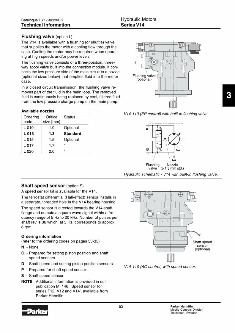
53 Parker HannifinMobile Controls DivisionTrollhättan, Sweden
Hydraulic MotorsSeries V14
3
Catalogue HY17-8223/UK
A
B
Flushing valve (option L)The V14 is available with a flushing (or shuttle) valvethat supplies the motor with a cooling flow through thecase. Cooling the motor may be required when operat-ing at high speeds and/or power levels.
The flushing valve consists of a three-position, three-way spool valve built into the connection module. It con-nects the low pressure side of the main circuit to a nozzle(optional sizes below) that empties fluid into the motorcase.
In a closed circuit transmission, the flushing valve re-moves part of the fluid in the main loop. The removedfluid is continuously being replaced by cool, filtered fluidfrom the low pressure charge pump on the main pump.
Available nozzles
Ordering Orifice Statuscode size [mm]
L 010 1.0 Optional
L 013 1.3 Standard
L 015 1.5 Optional
L 017 1.7 "
L 020 2.0 "
V14-110 (EP control) with built-in flushing valve.
Hydraulic schematic - V14 with built-in flushing valve.
Shaft speed sensor (option S)A speed sensor kit is available for the V14.
The ferrostat differential (Hall-effect) sensor installs ina separate, threaded hole in the V14 bearing housing.
The speed sensor is directed towards the V14 shaftflange and outputs a square wave signal within a fre-quency range of 5 Hz to 20 kHz. Number of pulses pershaft rev is 36 which, at 5 Hz, corresponds to approx.8 rpm.
Ordering information(refer to the ordering codes on pages 33-35)
N - None
C - Prepared for setting piston position and shaftspeed sensors
D - Shaft speed and setting piston position sensors
P - Prepared for shaft speed sensor
S - Shaft speed sensor.
NOTE: Additional information is provided in ourpublication MI 146, ‘Speed sensor forseries F12, V12 and V14’, available fromParker Hannifin.
Flushing valve(optional)
Flushing Nozzlevalve (φ 1.3 mm std.)
V14-110 (AC control) with speed sensor.
Technical Information
Shaft speedsensor
(optional)
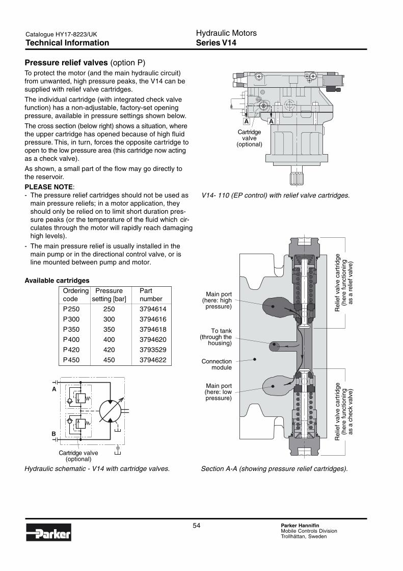
54 Parker HannifinMobile Controls DivisionTrollhättan, Sweden
Hydraulic MotorsSeries V14
Catalogue HY17-8223/UK
A A
A
B
Pressure relief valves (option P)To protect the motor (and the main hydraulic circuit)from unwanted, high pressure peaks, the V14 can besupplied with relief valve cartridges.
The individual cartridge (with integrated check valvefunction) has a non-adjustable, factory-set openingpressure, available in pressure settings shown below.
The cross section (below right) shows a situation, wherethe upper cartridge has opened because of high fluidpressure. This, in turn, forces the opposite cartridge toopen to the low pressure area (this cartridge now actingas a check valve).
As shown, a small part of the flow may go directly tothe reservoir.
PLEASE NOTE:- The pressure relief cartridges should not be used as
main pressure reliefs; in a motor application, theyshould only be relied on to limit short duration pres-sure peaks (or the temperature of the fluid which cir-culates through the motor will rapidly reach damaginghigh levels).
- The main pressure relief is usually installed in themain pump or in the directional control valve, or isline mounted between pump and motor.
Available cartridges
Ordering Pressure Partcode setting [bar] number
P250 250 3794614
P300 300 3794616
P350 350 3794618
P400 400 3794620
P420 420 3793529
P450 450 3794622
V14- 110 (EP control) with relief valve cartridges.
Hydraulic schematic - V14 with cartridge valves. Section A-A (showing pressure relief cartridges).
Main port(here: high
pressure)
To tank(through the
housing)
Connectionmodule
Main port(here: lowpressure)
Rel
ief v
alve
car
trid
geR
elie
f val
ve c
artr
idge
(her
e fu
nctio
ning
(her
e fu
nctio
ning
as a
che
ck v
alve
)as
a r
elie
f val
ve)
Cartridgevalve
(optional)
Cartridge valve(optional)
Technical Information
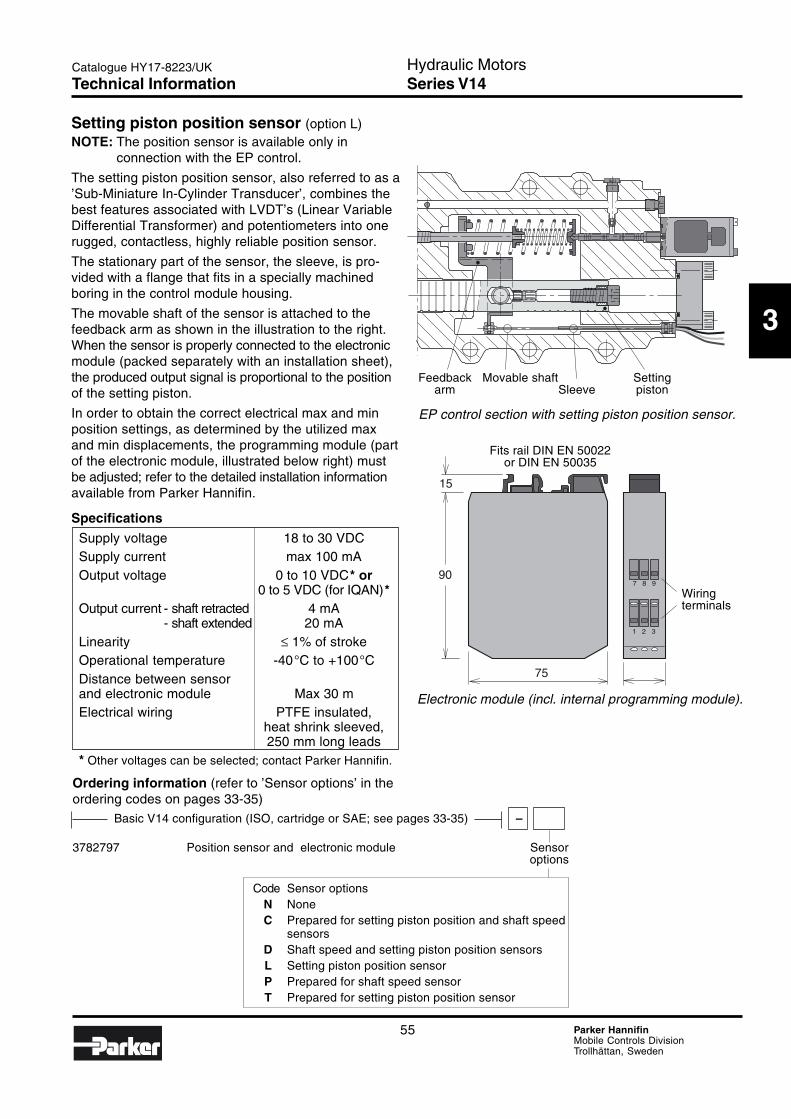
55 Parker HannifinMobile Controls DivisionTrollhättan, Sweden
Hydraulic MotorsSeries V14
3
Catalogue HY17-8223/UK
7 8 9
1 2 3
75
90
15
Basic V14 configuration (ISO, cartridge or SAE; see pages 33-35) –
3782797 Position sensor and electronic module Sensoroptions
Setting piston position sensor (option L)NOTE: The position sensor is available only in
connection with the EP control.
The setting piston position sensor, also referred to as a’Sub-Miniature In-Cylinder Transducer’, combines thebest features associated with LVDT’s (Linear VariableDifferential Transformer) and potentiometers into onerugged, contactless, highly reliable position sensor.
The stationary part of the sensor, the sleeve, is pro-vided with a flange that fits in a specially machinedboring in the control module housing.
The movable shaft of the sensor is attached to thefeedback arm as shown in the illustration to the right.When the sensor is properly connected to the electronicmodule (packed separately with an installation sheet),the produced output signal is proportional to the positionof the setting piston.
In order to obtain the correct electrical max and minposition settings, as determined by the utilized maxand min displacements, the programming module (partof the electronic module, illustrated below right) mustbe adjusted; refer to the detailed installation informationavailable from Parker Hannifin.
Specifications
Supply voltage 18 to 30 VDCSupply current max 100 mAOutput voltage 0 to 10 VDC* or
0 to 5 VDC (for IQAN)*Output current - shaft retracted 4 mA
- shaft extended 20 mALinearity ≤ 1% of strokeOperational temperature -40°C to +100°CDistance between sensorand electronic module Max 30 mElectrical wiring PTFE insulated,
heat shrink sleeved,250 mm long leads
* Other voltages can be selected; contact Parker Hannifin.
EP control section with setting piston position sensor.
Electronic module (incl. internal programming module).
Code Sensor optionsN NoneC Prepared for setting piston position and shaft speed
sensorsD Shaft speed and setting piston position sensorsL Setting piston position sensorP Prepared for shaft speed sensorT Prepared for setting piston position sensor
Wiringterminals
Fits rail DIN EN 50022or DIN EN 50035
Feedback Movable shaft Settingarm Sleeve piston
Ordering information (refer to ’Sensor options’ in theordering codes on pages 33-35)
Technical Information

56 Parker HannifinMobile Controls DivisionTrollhättan, Sweden
Hydraulic MotorsSeries T12
Catalogue HY17-8223/UK
Notes
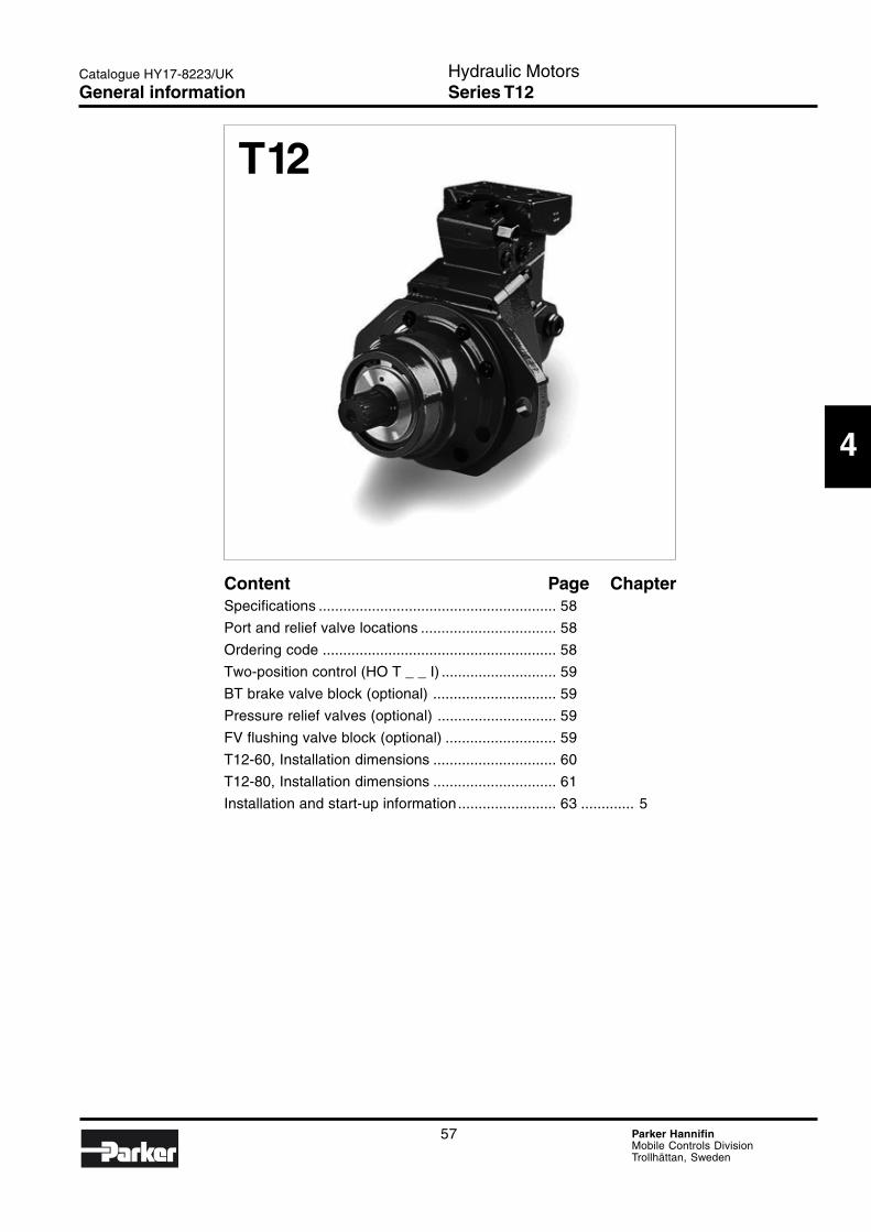
57 Parker HannifinMobile Controls DivisionTrollhättan, Sweden
Hydraulic MotorsSeries T12
4
Catalogue HY17-8223/UK
Content Page ChapterSpecifications .......................................................... 58
Port and relief valve locations ................................. 58
Ordering code ......................................................... 58
Two-position control (HO T _ _ I) ............................ 59
BT brake valve block (optional) .............................. 59
Pressure relief valves (optional) ............................. 59
FV flushing valve block (optional) ........................... 59
T12-60, Installation dimensions .............................. 60
T12-80, Installation dimensions .............................. 61
Installation and start-up information........................ 63 ............. 5
T12
General information
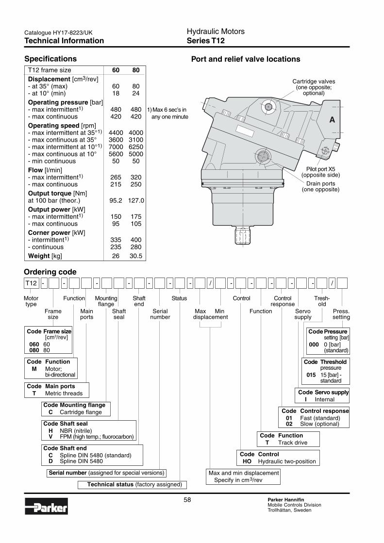
58 Parker HannifinMobile Controls DivisionTrollhättan, Sweden
Hydraulic MotorsSeries T12
Catalogue HY17-8223/UK
Ordering codeT12 - - - - - - - / - - - - - /
Motor Function Mounting Shaft Status Control Control Tresh-type flange end response old
Frame Main Shaft Serial Max Min Function Servo Press.size ports seal number displacement supply setting
A
Code Pressuresetting [bar]
000 0 [bar](standard)
Code Thresholdpressure
015 15 [bar] -standard
Code Servo supplyI Internal
Code Control response01 Fast (standard)02 Slow (optional)
Code FunctionT Track drive
Code ControlHO Hydraulic two-position
Max and min displacementSpecify in cm3/rev
Code Frame size [cm3/rev]
060 60080 80
Code FunctionM Motor;
bi-directional
Code Main portsT Metric threads
Code Mounting flangeC Cartridge flange
Code Shaft sealH NBR (nitrile)V FPM (high temp.; fluorocarbon)
Code Shaft endC Spline DIN 5480 (standard)D Spline DIN 5480
Serial number (assigned for special versions)
Technical status (factory assigned)
SpecificationsT12 frame size 60 80Displacement [cm3/rev]- at 35° (max) 60 80- at 10° (min) 18 24Operating pressure [bar]- max intermittent1) 480 480 1)Max 6 sec’s in- max continuous 420 420 any one minute
Operating speed [rpm]- max intermittent at 35°1) 4400 4000- max continuous at 35° 3600 3100- max intermittent at 10°1) 7000 6250- max continuous at 10° 5600 5000- min continuous 50 50Flow [l/min]- max intermittent1) 265 320- max continuous 215 250Output torque [Nm]at 100 bar (theor.) 95.2 127.0Output power [kW]- max intermittent1) 150 175- max continuous 95 105Corner power [kW]- intermittent1) 335 400- continuous 235 280Weight [kg] 26 30.5
Port and relief valve locations
Cartridge valves(one opposite;
optional)
Pilot port X5(opposite side)
Drain ports(one opposite)
Technical Information
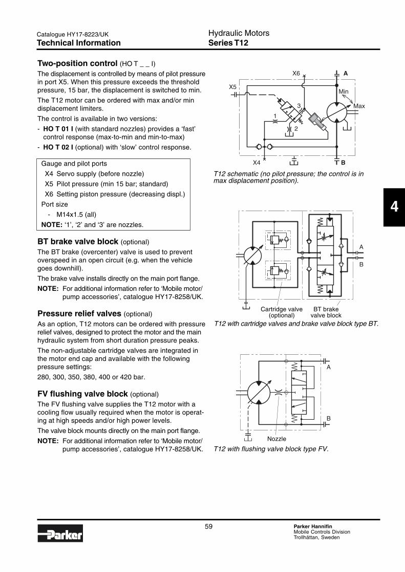
59 Parker HannifinMobile Controls DivisionTrollhättan, Sweden
Hydraulic MotorsSeries T12
4
Catalogue HY17-8223/UK
A
B
A
B
X6
1
2
3
Min
Max
A
X5
X4 B
Two-position control (HO T _ _ I)
The displacement is controlled by means of pilot pressurein port X5. When this pressure exceeds the thresholdpressure, 15 bar, the displacement is switched to min.
The T12 motor can be ordered with max and/or mindisplacement limiters.
The control is available in two versions:
- HO T 01 I (with standard nozzles) provides a ‘fast’control response (max-to-min and min-to-max)
- HO T 02 I (optional) with ‘slow’ control response.
Gauge and pilot ports
X4 Servo supply (before nozzle)
X5 Pilot pressure (min 15 bar; standard)
X6 Setting piston pressure (decreasing displ.)
Port size
- M14x1.5 (all)
NOTE: ‘1’, ‘2’ and ‘3’ are nozzles.
BT brake valve block (optional)
The BT brake (overcenter) valve is used to preventoverspeed in an open circuit (e.g. when the vehiclegoes downhill).
The brake valve installs directly on the main port flange.
NOTE: For additional information refer to ‘Mobile motor/pump accessories’, catalogue HY17-8258/UK.
Pressure relief valves (optional)
As an option, T12 motors can be ordered with pressurerelief valves, designed to protect the motor and the mainhydraulic system from short duration pressure peaks.
The non-adjustable cartridge valves are integrated inthe motor end cap and available with the followingpressure settings:
280, 300, 350, 380, 400 or 420 bar.
FV flushing valve block (optional)
The FV flushing valve supplies the T12 motor with acooling flow usually required when the motor is operat-ing at high speeds and/or high power levels.
The valve block mounts directly on the main port flange.
NOTE: For additional information refer to ‘Mobile motor/pump accessories’, catalogue HY17-8258/UK.
T12 with cartridge valves and brake valve block type BT.
T12 with flushing valve block type FV.
T12 schematic (no pilot pressure; the control is inmax displacement position).
Cartridge valve BT brake(optional) valve block
Nozzle
Technical Information
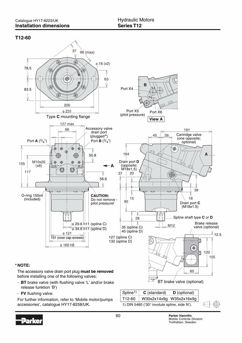
60 Parker HannifinMobile Controls DivisionTrollhättan, Sweden
Hydraulic MotorsSeries T12
Catalogue HY17-8223/UK
A
BX4
X6
37
63
φ 18 (x2)
200
127 max
66 191
3945
164
2037
15
28
39
18
120155
90
155
117
M12
φ 121
φ 160 h8
φ 231
96 (max)
A
60
M10x20(x8)
Spline1) C (standard) D (optional)
T12-60 W30x2x14x9g W35x2x16x9g1) DIN 5480 (‘30° involute spline, side fit’).
T12-60
78.5
83.5 Port X4
Port X5(pilot pressure)
Port X6
View AType C mounting flange
Accessory valvedrain port
(plugged*)Port A (3/4”) Port B (3/4”)
50.8
56.6
O-ring 150x4(included)
φ 29.6 h11 (spline C)φ 34.6 h11 (spline D)
151 (over cap screws)
35 (spline C)40 (spline D)
127 (spline C)132 (spline D)
Spline shaft type C or D
Brake releasevalve (optional)
12.5
BT brake valve (optional)
* NOTE:
The accessory valve drain port plug must be removedbefore installing one of the following valves:
- BT brake valve (with flushing valve ‘L’ and/or brakerelease funktion ‘B’)
- FV flushing valve.
For further information, refer to ‘Mobile motor/pumpsaccessories’, catalogue HY17-8258/UK.
CAUTION:Do not remove -pilot pressure! Drain port C
(M18x1.5)
Cartridge valve(one opposite;
optional)
Drain port D(opposite;M18x1,5)
Installation dimensions
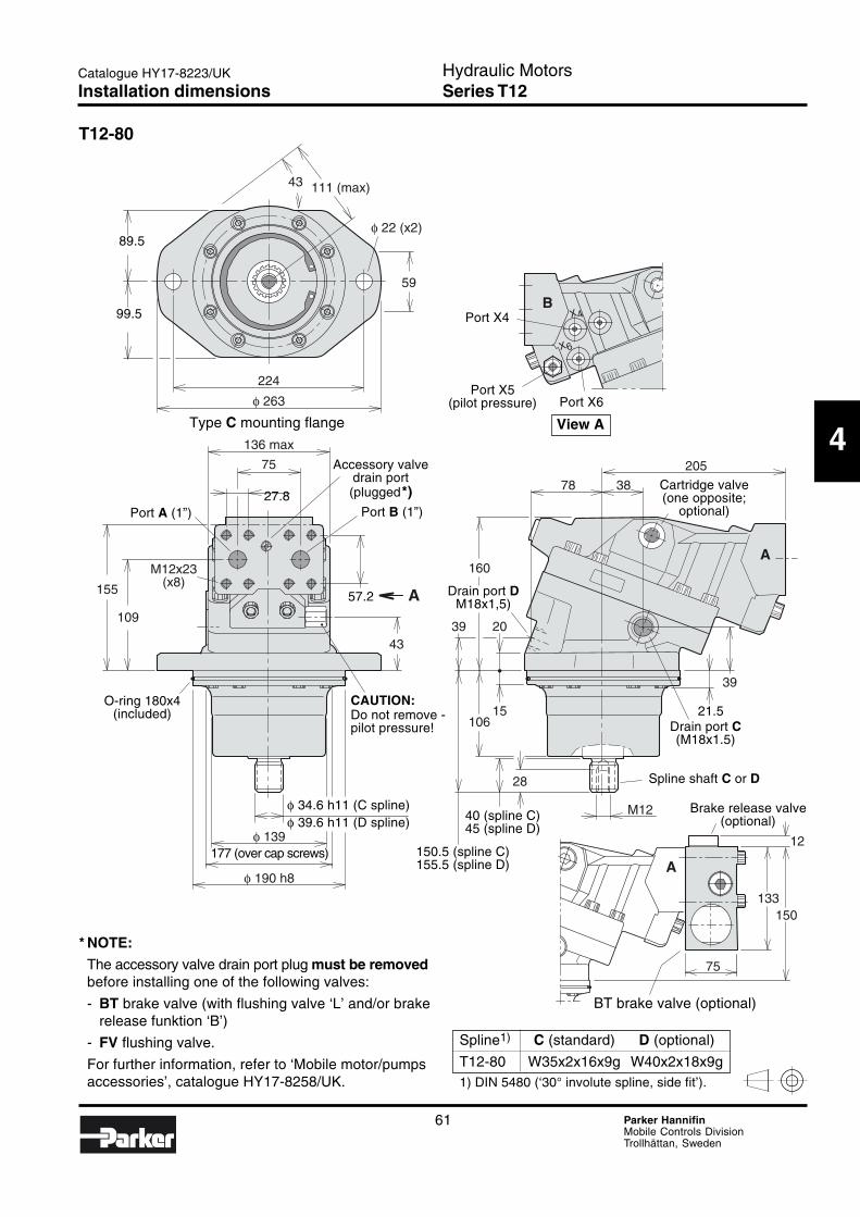
61 Parker HannifinMobile Controls DivisionTrollhättan, Sweden
Hydraulic MotorsSeries T12
4
Catalogue HY17-8223/UK
A
BX4
X6
A
43
59
φ 22 (x2)
224
136 max
75
43
205
3878
160
2039
15
28
39
133150
12
106
155
109
M12x23(x8)
M12
φ 139
φ 190 h8
φ 263
111 (max)
A
75
T12-80
Spline1) C (standard) D (optional)
T12-80 W35x2x16x9g W40x2x18x9g1) DIN 5480 (‘30° involute spline, side fit’).
89.5
99.5
O-ring 180x4(included)
Type C mounting flange
Port X4
Port X5(pilot pressure)
View A
27.8Port A (1”) Port B (1”)
Accessory valvedrain port(plugged*)
57.2
CAUTION:Do not remove -pilot pressure!
φ 34.6 h11 (C spline)φ 39.6 h11 (D spline)
177 (over cap screws) 150.5 (spline C)155.5 (spline D)
40 (spline C)45 (spline D)
21.5Drain port C(M18x1.5)
Spline shaft C or D
Brake release valve(optional)
BT brake valve (optional)
Port X6
* NOTE:
The accessory valve drain port plug must be removedbefore installing one of the following valves:
- BT brake valve (with flushing valve ‘L’ and/or brakerelease funktion ‘B’)
- FV flushing valve.
For further information, refer to ‘Mobile motor/pumpsaccessories’, catalogue HY17-8258/UK.
Cartridge valve(one opposite;
optional)
Drain port DM18x1,5)
Installation dimensions

62 Parker HannifinMobile Controls DivisionTrollhättan, Sweden
Hydraulic MotorsSeries T12
Catalogue HY17-8223/UK
Notes
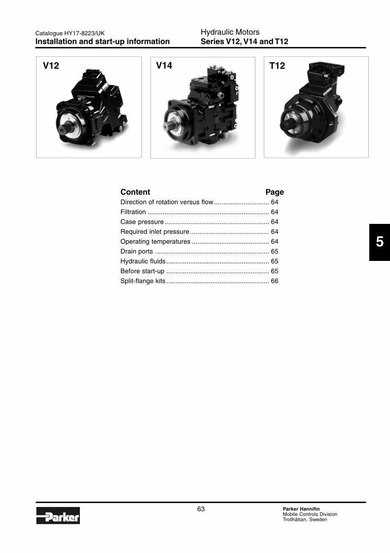
63 Parker HannifinMobile Controls DivisionTrollhättan, Sweden
Hydraulic MotorsSeries V12, V14 and T12
Catalogue HY17-8223/UK
Content PageDirection of rotation versus flow .............................. 64
Filtration .................................................................. 64
Case pressure ......................................................... 64
Required inlet pressure ........................................... 64
Operating temperatures .......................................... 64
Drain ports .............................................................. 65
Hydraulic fluids ........................................................ 65
Before start-up ........................................................ 65
Split-flange kits ........................................................ 66
Installation and start-up information
5
V12 V14 T12
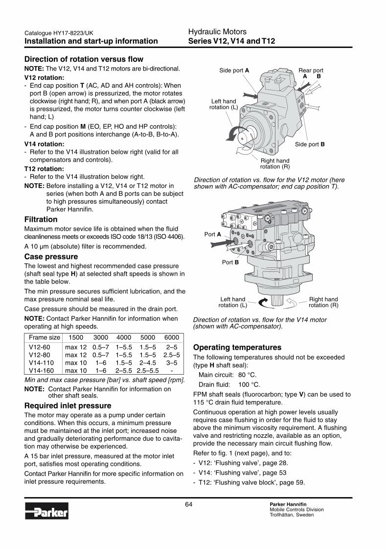
64 Parker HannifinMobile Controls DivisionTrollhättan, Sweden
Hydraulic MotorsSeries V12, V14 and T12
Catalogue HY17-8223/UK
Direction of rotation versus flowNOTE: The V12, V14 and T12 motors are bi-directional.V12 rotation:- End cap position T (AC, AD and AH controls): When
port B (open arrow) is pressurized, the motor rotatesclockwise (right hand; R), and when port A (black arrow)is pressurized, the motor turns counter clockwise (lefthand; L)
- End cap position M (EO, EP, HO and HP controls):A and B port positions interchange (A-to-B, B-to-A).
V14 rotation:- Refer to the V14 illustration below right (valid for all
compensators and controls).T12 rotation:- Refer to the V14 illustration below right.NOTE: Before installing a V12, V14 or T12 motor in
series (when both A and B ports can be subjectto high pressures simultaneously) contactParker Hannifin.
FiltrationMaximum motor sevice life is obtained when the fluidcleanlineness meets or exceeds ISO code 18/13 (ISO 4406).
A 10 µm (absolute) filter is recommended.
Case pressureThe lowest and highest recommended case pressure(shaft seal type H) at selected shaft speeds is shown inthe table below.
The min pressure secures sufficient lubrication, and themax pressure nominal seal life.
Case pressure should be measured in the drain port.
NOTE: Contact Parker Hannifin for information whenoperating at high speeds.
Frame size 1500 3000 4000 5000 6000
V12-60 max 12 0.5–7 1–5.5 1.5–5 2–5V12-80 max 12 0.5–7 1–5.5 1.5–5 2.5–5V14-110 max 10 1–6 1.5–5 2–4.5 3–5V14-160 max 10 1–6 2–5.5 2.5–5.5 -
Min and max case pressure [bar] vs. shaft speed [rpm].NOTE: Contact Parker Hannifin for information on
other shaft seals.
Required inlet pressureThe motor may operate as a pump under certainconditions. When this occurs, a minimum pressuremust be maintained at the inlet port; increased noiseand gradually deteriorating performance due to cavita-tion may otherwise be experienced.
A 15 bar inlet pressure, measured at the motor inletport, satisfies most operating conditions.
Contact Parker Hannifin for more specific information oninlet pressure requirements.
Operating temperaturesThe following temperatures should not be exceeded(type H shaft seal):
Main circuit: 80 °C.
Drain fluid: 100 °C.
FPM shaft seals (fluorocarbon; type V) can be used to115 °C drain fluid temperature.
Continuous operation at high power levels usuallyrequires case flushing in order for the fluid to stayabove the minimum viscosity requirement. A flushingvalve and restricting nozzle, available as an option,provide the necessary main circuit flushing flow.
Refer to fig. 1 (next page), and to:
- V12: ‘Flushing valve’, page 28.
- V14: ‘Flushing valve’, page 53
- T12: ‘Flushing valve block’, page 59.
Direction of rotation vs. flow for the V12 motor (hereshown with AC-compensator; end cap position T).
Direction of rotation vs. flow for the V14 motor(shown with AC-compensator).
Right handrotation (R)
Side port A Rear portA B
Left handrotation (L)
Side port B
Left handrotation (L)
Right handrotation (R)
Port A
Port B
Installation and start-up information
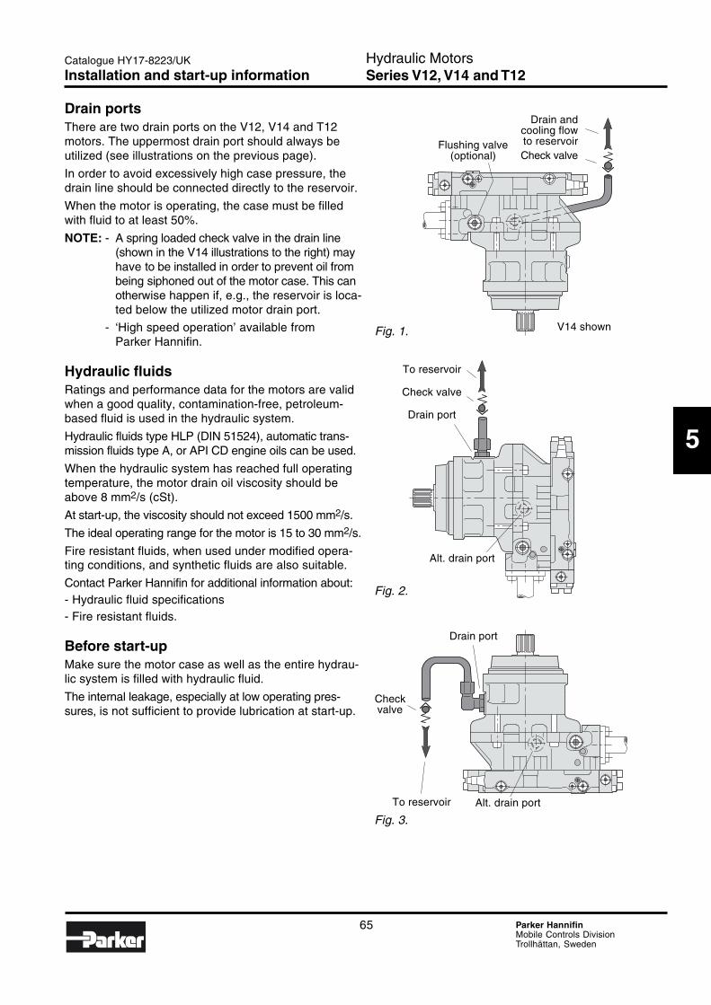
65 Parker HannifinMobile Controls DivisionTrollhättan, Sweden
Hydraulic MotorsSeries V12, V14 and T12
Catalogue HY17-8223/UK
Drain portsThere are two drain ports on the V12, V14 and T12motors. The uppermost drain port should always beutilized (see illustrations on the previous page).
In order to avoid excessively high case pressure, thedrain line should be connected directly to the reservoir.
When the motor is operating, the case must be filledwith fluid to at least 50%.
NOTE: - A spring loaded check valve in the drain line(shown in the V14 illustrations to the right) mayhave to be installed in order to prevent oil frombeing siphoned out of the motor case. This canotherwise happen if, e.g., the reservoir is loca-ted below the utilized motor drain port.
- ‘High speed operation’ available fromParker Hannifin.
Hydraulic fluidsRatings and performance data for the motors are validwhen a good quality, contamination-free, petroleum-based fluid is used in the hydraulic system.
Hydraulic fluids type HLP (DIN 51524), automatic trans-mission fluids type A, or API CD engine oils can be used.
When the hydraulic system has reached full operatingtemperature, the motor drain oil viscosity should beabove 8 mm2/s (cSt).
At start-up, the viscosity should not exceed 1500 mm2/s.
The ideal operating range for the motor is 15 to 30 mm2/s.
Fire resistant fluids, when used under modified opera-ting conditions, and synthetic fluids are also suitable.
Contact Parker Hannifin for additional information about:- Hydraulic fluid specifications- Fire resistant fluids.
Before start-upMake sure the motor case as well as the entire hydrau-lic system is filled with hydraulic fluid.
The internal leakage, especially at low operating pres-sures, is not sufficient to provide lubrication at start-up.
Fig. 1.
Fig. 2.
Fig. 3.
Flushing valve(optional)
Drain andcooling flowto reservoirCheck valve
To reservoir
Check valve
Drain port
Alt. drain port
Drain port
Checkvalve
Alt. drain portTo reservoir
V14 shown
Installation and start-up information
5
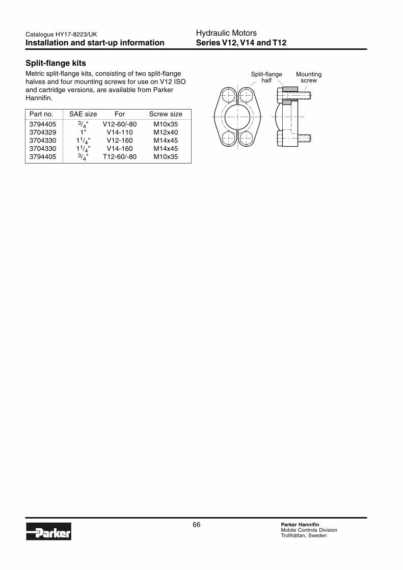
66 Parker HannifinMobile Controls DivisionTrollhättan, Sweden
Hydraulic MotorsSeries V12, V14 and T12
Catalogue HY17-8223/UK
Split-flange kitsMetric split-flange kits, consisting of two split-flangehalves and four mounting screws for use on V12 ISOand cartridge versions, are available from ParkerHannifin.
Part no. SAE size For Screw size
3794405 3/4" V12-60/-80 M10x353704329 1" V14-110 M12x403704330 11/4" V12-160 M14x453704330 11/4" V14-160 M14x453794405 3/4" T12-60/-80 M10x35
Split-flange Mountinghalf screw
Installation and start-up information
67 Parker HannifinMobile Controls DivisionTrollhättan, Sweden
Hydraulic MotorsSeries V12, V14 and T12
Catalogue HY17-8223/UK
General
5
Offer of SalePlease contact your Parker representation for a detailed ”Offer of Sale”.
FAILURE OR IMPROPER SELECTION OR IMPROPER USE OF THE PRODUCTS AND/OR SYSTEMS DESCRIBEDHEREIN OR RELATED ITEMS CAN CAUSE DEATH, PERSONAL INJURY AND PROPERTY DAMAGE.
This document and other information from Parker Hannifin Corporation, its subsidiaries and authorized distributors provideproduct and/or system options for further investigation by users having technical expertise. It is important that you analyze allaspects of your application, including consequences of any failure, and review the information concerning the product or systemin the current product catalogue. Due to the variety of operating conditions and applications for these products or systems, theuser, through its own analysis and testing, is solely responsible for making the final selection of the products and systems andassuring that all performance, safety and warning requirements of the application are met.
The products described herein, including without limitation, product features, specifications, designs, availability and pricing, aresubject to change by Parker Hannifin Corporation and its subsidiaries at any time without notice.
WARNING!
Parker Hannifin is the world’s premier supplier of motion and control systemsand solutions, with sales and manufacturing facilities throughout the world. Forproduct information and details of your nearest Parker sales office, visit us atwww.parker.com/euro_mcd or call free on 00800 2727 5374.
Hydraulics GroupSales Offices
AustriaWiener NeustadtTel: +43 (0)2622 23501Fax: +43 (0)2622 66212
BelgiumNivellesTel: +32 (0)67 280 900Fax: +32 (0)67 280 999
Czech RepublicPragueTel: +420 2 830 85 224Fax: +420 2 830 85 360
DenmarkBallerupTel: +45 4356 0400Fax: +45 4373 8431
FinlandVantaaTel: +358 (0)9 4767 31Fax: +358 (0)9 4767 3200
FranceContamine-sur-ArveTel: +33 (0)450 25 80 25Fax: +33 (0)450 03 67 37
GermanyKaarstTel: +49 (0)2131 4016 0Fax: +49 (0)2131 4016 9199
HungaryBudapestTel: +36 (06)1 220 4155Fax: +36 (06)1 422 1525
IrelandDublinTel: +353 (0)1 293 9999Fax: +353 (0)1 293 9900
ItalyCorsico (MI)Tel: +39 02 45 19 21Fax: +39 02 4 47 93 40
The NetherlandsOldenzaalTel: +31 (0)541 585000Fax: +31 (0)541 585459
NorwaySkiTel: +47 64 91 10 00Fax: +47 64 91 10 90
PolandWarsawTel: +48 (0)22 573 24 63Fax: +48 (0)22 573 24 90
PortugalLeca da PalmeiraTel: +351 22 9997 360Fax: +351 22 9961 527
SlovakiaRef. Czech Republic
SpainMadridTel: +34 91 675 73 00Fax: +34 91 675 77 11
SwedenSpångaTel: +46 (0)8 597 950 00Fax: +46 (0)8 597 951 10
United KingdomWarwickTel: +44 (0)1926 317 878Fax: +44 (0)1926 317 855
InternationalEurope
Catalogue HY17-8223/UKPDF 11/04
© Copyright 2004Parker Hannifin CorporationAll rights reserved.
AustraliaCastle HillTel: +61 (0)2-9634 7777Fax: +61 (0)2-9899 6184
CanadaMilton, OntarioTel: +1 905-693-3000Fax: +1 905-876-0788
ChinaBeijingTel: +86 10 6561 0520Fax: +86 10 6561 0526
Asia Pacific GroupHong Kong, KowloonTel: +852 2428 8008Fax: +852 2425 6896
IndiaMumbaiTel: +91 22 7907081Fax: +91 22 7907080
JapanTokyoTel: +(81) 3 6408 3900Fax: +(81) 3 5449 7201
Latin America GroupBrazilTel: +55 12 3954-5100Fax: +55 12 3954-5266
South AfricaKempton ParkTel: +27 (0)11-961 0700Fax: +27 (0)11-392 7213
USACleveland (industrial)Tel: +1 216-896-3000Fax: +1 216-896-4031Lincolnshire (mobile)Tel: +1 847-821-1500Fax: +1 847-821-7600