FJ Series General Purpose Hydraulic Cylinder -...
8
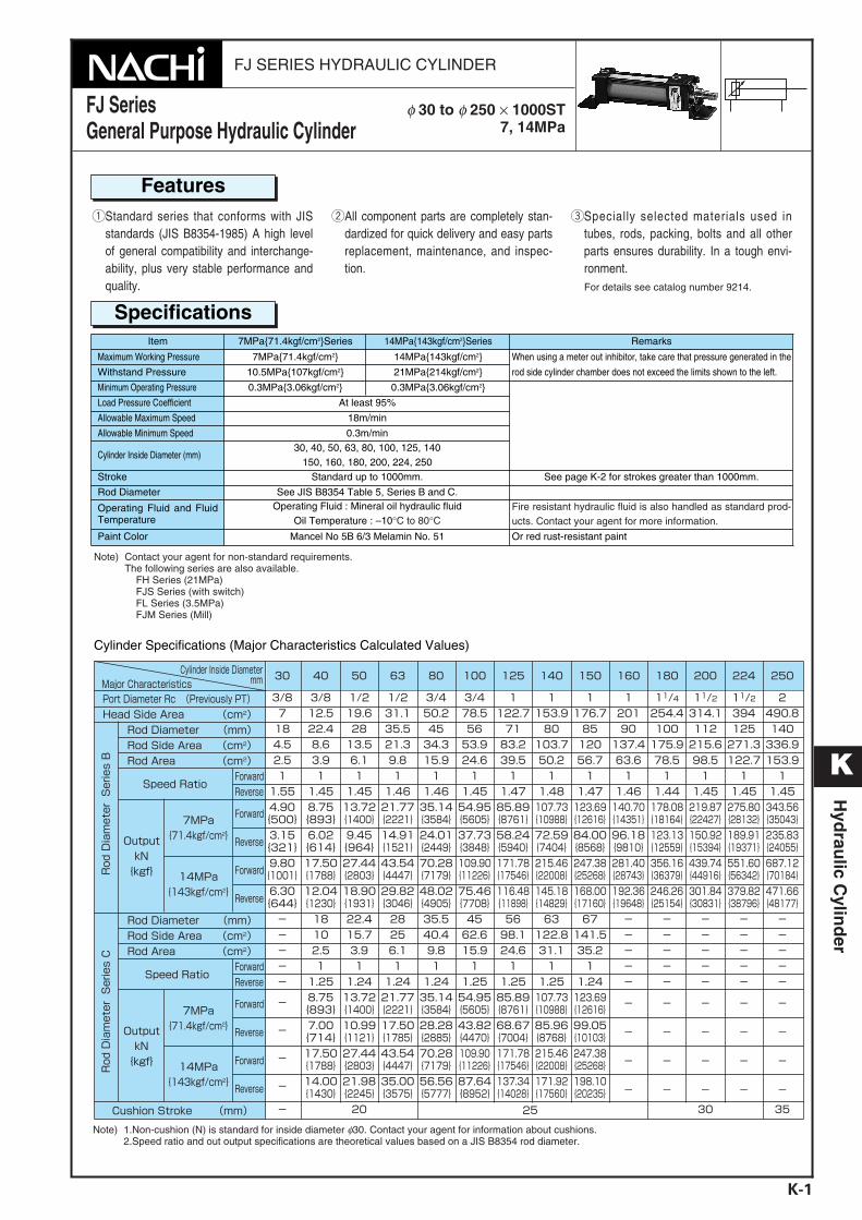
FJ SERIES HYDRAULIC CYLINDER FJ Series General Purpose Hydraulic Cylinder φ 30 to φ 250 × 1000ST 7, 14MPa K K-1 Hydraulic Cylinder Features qStandard series that conforms with JIS standards (JIS B8354-1985) A high level of general compatibility and interchange- ability, plus very stable performance and quality. wAll component parts are completely stan- dardized for quick delivery and easy parts replacement, maintenance, and inspec- tion. eSpecially selected materials used in tubes, rods, packing, bolts and all other parts ensures durability. In a tough envi- ronment. For details see catalog number 9214. Note) Contact your agent for non-standard requirements. The following series are also available. FH Series (21MPa) FJS Series (with switch) FL Series (3.5MPa) FJM Series (Mill) Note) 1.Non-cushion (N) is standard for inside diameter φ30. Contact your agent for information about cushions. 2.Speed ratio and out output specifications are theoretical values based on a JIS B8354 rod diameter. Specifications Item 7MPa{71.4kgf/cm 2 }Series 14MPa{143kgf/cm 2 }Series Remarks Maximum Working Pressure 7MPa{71.4kgf/cm 2 } 14MPa{143kgf/cm 2 } When using a meter out inhibitor, take care that pressure generated in the rod side cylinder chamber does not exceed the limits shown to the left. Withstand Pressure 10.5MPa{107kgf/cm 2 } 21MPa{214kgf/cm 2 } Minimum Operating Pressure 0.3MPa{3.06kgf/cm 2 } 0.3MPa{3.06kgf/cm 2 } Load Pressure Coefficient At least 95% Allowable Maximum Speed 18m/min Allowable Minimum Speed 0.3m/min Cylinder Inside Diameter (mm) 30, 40, 50, 63, 80, 100, 125, 140 150, 160, 180, 200, 224, 250 Stroke Standard up to 1000mm. See page K-2 for strokes greater than 1000mm. Rod Diameter See JIS B8354 Table 5, Series B and C. Operating Fluid and Fluid Temperature Operating Fluid : Mineral oil hydraulic fluid Oil Temperature : –10°C to 80°C Fire resistant hydraulic fluid is also handled as standard prod- ucts. Contact your agent for more information. Paint Color Mancel No 5B 6/3 Melamin No. 51 Or red rust-resistant paint Cylinder Specifications (Major Characteristics Calculated Values)
-
Upload
truongthuy -
Category
Documents
-
view
224 -
download
0
Transcript of FJ Series General Purpose Hydraulic Cylinder -...
FJ SERIES HYDRAULIC CYLINDER
FJ Series General Purpose Hydraulic Cylinder
φ 30 to φ 250 × 1000ST7, 14MPa
K
K-1
Hyd
raulic C
ylind
er
FeaturesqStandard series that conforms with JIS
standards (JIS B8354-1985) A high levelof general compatibility and interchange-ability, plus very stable performance andquality.
wAll component parts are completely stan-dardized for quick delivery and easy partsreplacement, maintenance, and inspec-tion.
eSpecially selected materials used intubes, rods, packing, bolts and all otherparts ensures durability. In a tough envi-ronment.For details see catalog number 9214.
Note) Contact your agent for non-standard requirements. The following series are also available.
FH Series (21MPa) FJS Series (with switch) FL Series (3.5MPa) FJM Series (Mill)
Note) 1.Non-cushion (N) is standard for inside diameter φ30. Contact your agent for information about cushions. 2.Speed ratio and out output specifications are theoretical values based on a JIS B8354 rod diameter.
SpecificationsItem 7MPa{71.4kgf/cm2}Series 14MPa{143kgf/cm2}Series Remarks
Maximum Working Pressure 7MPa{71.4kgf/cm2} 14MPa{143kgf/cm2} When using a meter out inhibitor, take care that pressure generated in the
rod side cylinder chamber does not exceed the limits shown to the left.Withstand Pressure 10.5MPa{107kgf/cm2} 21MPa{214kgf/cm2}
Minimum Operating Pressure 0.3MPa{3.06kgf/cm2} 0.3MPa{3.06kgf/cm2}
Load Pressure Coefficient At least 95%
Allowable Maximum Speed 18m/min
Allowable Minimum Speed 0.3m/min
Cylinder Inside Diameter (mm)30, 40, 50, 63, 80, 100, 125, 140
150, 160, 180, 200, 224, 250Stroke Standard up to 1000mm. See page K-2 for strokes greater than 1000mm.
Rod Diameter See JIS B8354 Table 5, Series B and C.
Operating Fluid and FluidTemperature
Operating Fluid : Mineral oil hydraulic fluid Oil Temperature : –10°C to 80°C
Fire resistant hydraulic fluid is also handled as standard prod-ucts. Contact your agent for more information.
Paint Color Mancel No 5B 6/3 Melamin No. 51 Or red rust-resistant paint
Cylinder Specifications (Major Characteristics Calculated Values)
K Hydraulic Cylinder_E.q 03.11.20 2:01 PM Page 1
K
K-2
Hyd
raulic C
ylind
er
¡HandlingNote the following installation andhandling precautions to get the mostout of cylinder performance and toobtain the long service life for whichcylinders are designed.zCylinders are designed for rigidity.
Be sure to secure them in placewith bolts.
xInstall cylinders in a location thatallows their easy removal, mainte-nance, and inspection.
cWhen installing a cylinder in a loca-tion where the air quality is poor, orwhere there are large amounts ofdust, metal powder, or other conta-minants, install dust covers on therod and shell to protect them.
vWhen installing a cylinder, align itwith the center of the slide, andmake sure it is not subjected to lat-eral or rotational force by the pistonor rod. When lateral force is
unavoidable, make sure it does notexceed 1/100 of cylinder maximumoutput.
bWhen coupling the piston rod andmachinery, adjust so there is nounnecessary force applied to thepiston rod sliding bush.
nFor other details, see catalog num-ber 9214.
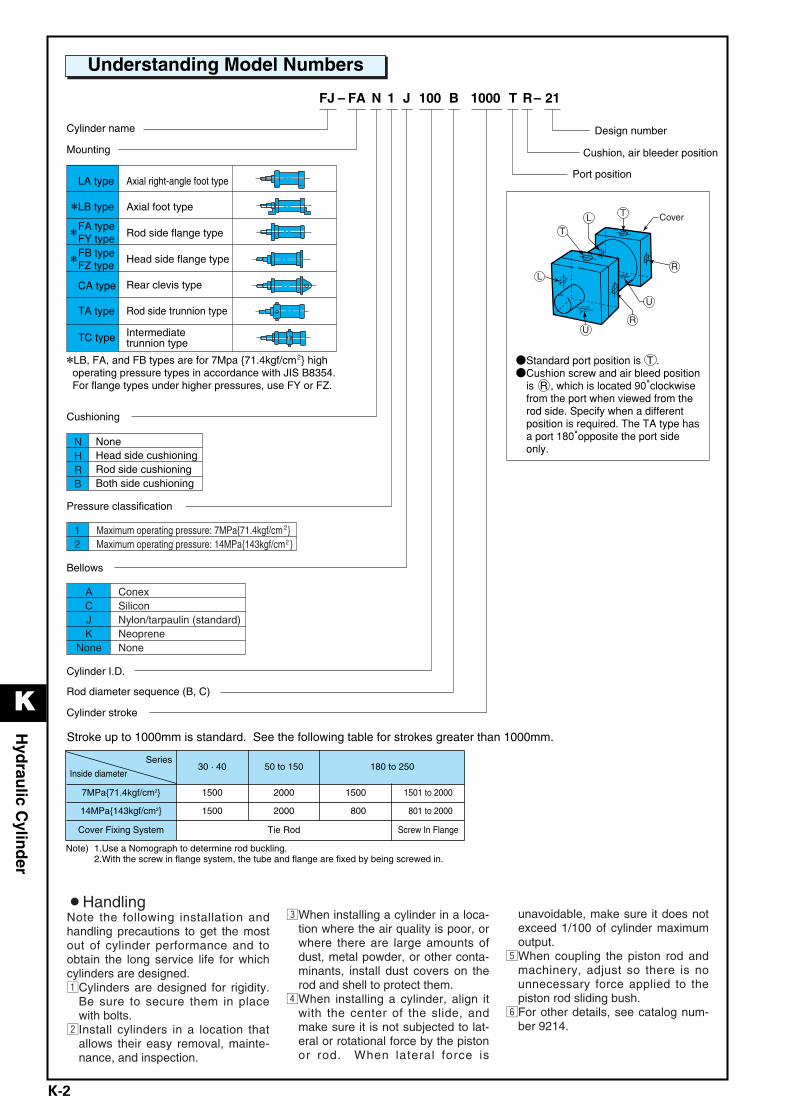
21–RT 1000 B100 J 1 N FA –FJ
Design number
Cushion, air bleeder position
Port position
Cylinder name
Mounting
Axial right-angle foot type
Axial foot type
Rod side flange type
Head side flange type
Rear clevis type
Rod side trunnion type
Intermediate trunnion type
Cushioning
Pressure classification
Bellows
Cylinder I.D.
Cylinder stroke
Rod diameter sequence (B, C)
NHRB
12
ConexSiliconNylon/tarpaulin (standard)NeopreneNone
Maximum operating pressure: 7MPa{71.4kgf/cm }Maximum operating pressure: 14MPa{143kgf/cm }
NoneHead side cushioningRod side cushioningBoth side cushioning
2
2
2
Cover
TL
L
U
U
R
R
T
Understanding Model Numbers
Stroke up to 1000mm is standard. See the following table for strokes greater than 1000mm.
Note) 1.Use a Nomograph to determine rod buckling. 2.With the screw in flange system, the tube and flange are fixed by being screwed in.
Series
Inside diameter30 · 40 50 to 150 180 to 250
7MPa{71.4kgf/cm2} 1500 2000 1500 1501 to 2000
14MPa{143kgf/cm2} 1500 2000 0800 801 to 2000
Cover Fixing System Tie Rod Screw In Flange
K Hydraulic Cylinder_E.q 03.11.20 2:01 PM Page 2
K
K-3
Hyd
raulic C
ylind
er
When there is concern about unbalanced load caused by rod tip freedom
TYPE TC. CA
TYPE LA. LB. TA. FA. FB(When there is complete load guide is not possible)
TYPE LA. LB. FA. FB(When load guide is unstable)
TYPE LA. LB. FA. FB(When there is complete load guide)
Cylinder diameter mm A
MPa{kgf/cm2}
250 200 150 125 100 80
Maximum pressure
7.1 21 36 71 143 214
0.7 2.1 3.5 7 14 21
Mounting Auxiliary Line D1 2 3 4 5
Auxiliary Line E
.05 .1
1
.2
2
.3
3
.4
4
.5
5
.75 1
10
1.5 2
20
3
30
4 5
50
10
100
15 20
200
30 50
500
100 250150
Rod O.D. mm F500 250180 150 125 100 80 60 50 40 30 25 20 16
Stroke mm G
(4000) (3000) (2500) (2000) (1500) 1000 500
Note) TC type is intermediate trunnion type
300 250
63 50 40 30
B
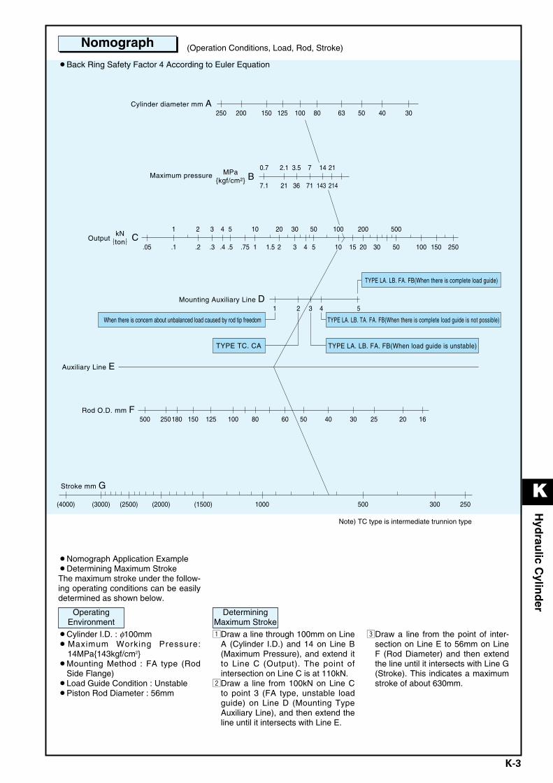
Nomograph
¡Back Ring Safety Factor 4 According to Euler Equation
(Operation Conditions, Load, Rod, Stroke)
¡Cylinder I.D. : φ100mm¡Maximum Working Pressure:
14MPa{143kgf/cm2}¡Mounting Method : FA type (Rod
Side Flange) ¡Load Guide Condition : Unstable¡Piston Rod Diameter : 56mm
zDraw a line through 100mm on LineA (Cylinder I.D.) and 14 on Line B(Maximum Pressure), and extend itto Line C (Output). The point ofintersection on Line C is at 110kN.
xDraw a line from 100kN on Line Cto point 3 (FA type, unstable loadguide) on Line D (Mounting TypeAuxiliary Line), and then extend theline until it intersects with Line E.
cDraw a line from the point of inter-section on Line E to 56mm on LineF (Rod Diameter) and then extendthe line until it intersects with Line G(Stroke). This indicates a maximumstroke of about 630mm.
¡Nomograph Application Example¡Determining Maximum StrokeThe maximum stroke under the follow-ing operating conditions can be easilydetermined as shown below.
OperatingEnvironment
DeterminingMaximum Stroke
K Hydraulic Cylinder_E.q 03.11.20 2:01 PM Page 3
K
K-4
Hyd
raulic C
ylind
er
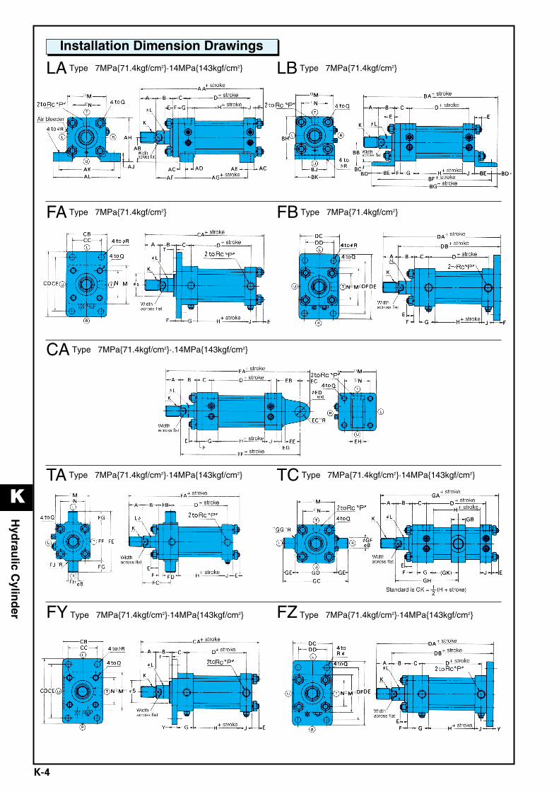
LA Type 7MPa{71.4kgf/cm2}·14MPa{143kgf/cm2} LB Type 7MPa{71.4kgf/cm2}
Installation Dimension Drawings
FA Type 7MPa{71.4kgf/cm2} FB Type 7MPa{71.4kgf/cm2}
CA Type 7MPa{71.4kgf/cm2}·.14MPa{143kgf/cm2}
TA Type 7MPa{71.4kgf/cm2}·14MPa{143kgf/cm2} TC Type 7MPa{71.4kgf/cm2}·14MPa{143kgf/cm2}
FY Type 7MPa{71.4kgf/cm2}·14MPa{143kgf/cm2} FZ Type 7MPa{71.4kgf/cm2}·14MPa{143kgf/cm2}
K Hydraulic Cylinder_E.q 03.11.20 2:01 PM Page 4
K
K-5
Hyd
raulic C
ylind
er
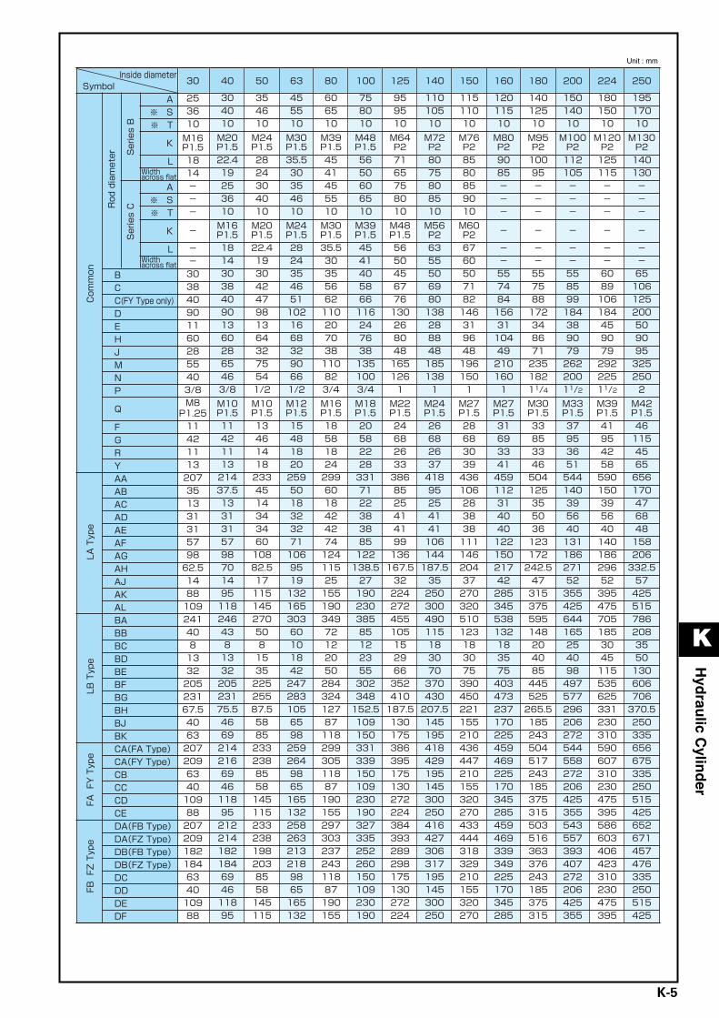
Unit : mm
K Hydraulic Cylinder_E.q 03.11.20 2:01 PM Page 5
K
K-6
Hyd
raulic C
ylind
er
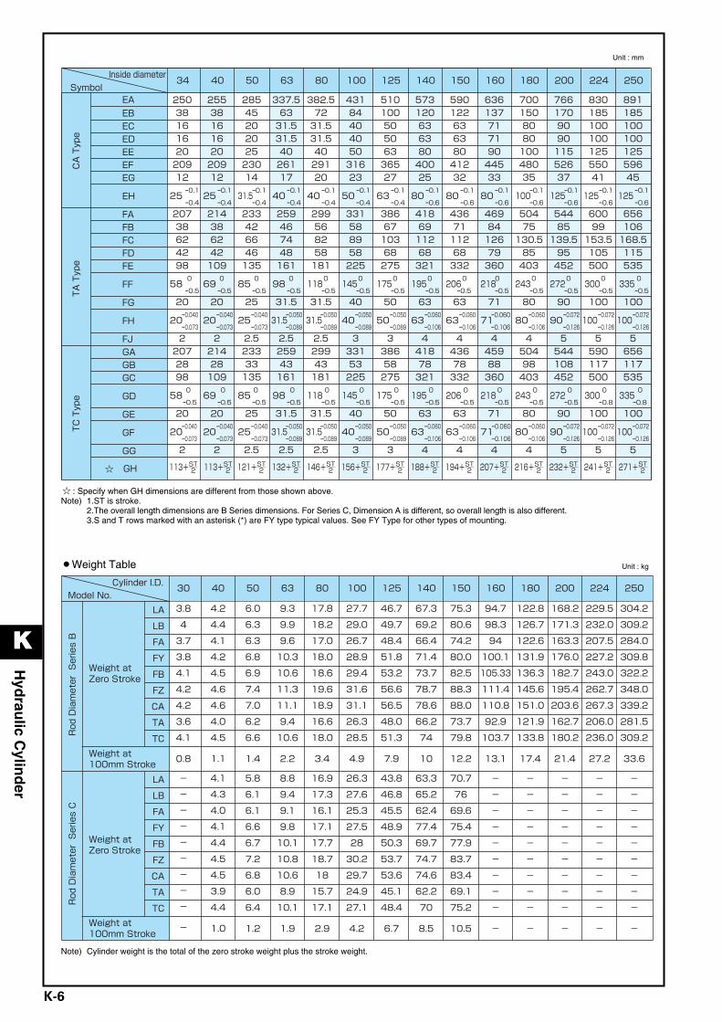
: Specify when GH dimensions are different from those shown above.Note) 1.ST is stroke.
2.The overall length dimensions are B Series dimensions. For Series C, Dimension A is different, so overall length is also different.3.S and T rows marked with an asterisk (*) are FY type typical values. See FY Type for other types of mounting.
Note) Cylinder weight is the total of the zero stroke weight plus the stroke weight.
Unit : mm
Unit : kg¡Weight Table
K Hydraulic Cylinder_E.q 03.11.20 2:01 PM Page 6
K
K-7
Hyd
raulic C
ylind
er
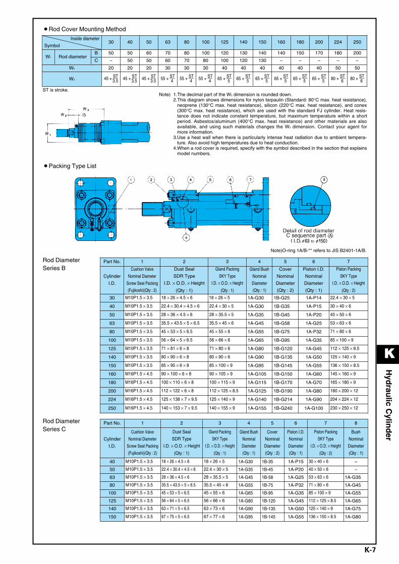
¡Packing Type List
Note)O-ring 1A/B-** refers to JIS B2401-1A/B.
Note) 1.The decimal part of the W3 dimension is rounded down. 2.This diagram shows dimensions for nylon tarpaulin (Standard: 80°C max. heat resistance),
neoprene (130°C max. heat resistance), silicon (220°C max. heat resistance), and conex(300°C max. heat resistance), which are used with the standard FJ cylinder. Heat resis-tance does not indicate constant temperature, but maximum temperature within a shortperiod. Asbestos/aluminum (400°C max. heat resistance) and other materials are alsoavailable, and using such materials changes the W3 dimension. Contact your agent formore information.
3.Use a heat wall when there is particularly intense heat radiation due to ambient tempera-ture. Also avoid high temperatures due to heat conduction.
4.When a rod cover is required, specify with the symbol described in the section that explainsmodel numbers.
ST is stroke.
¡Rod Cover Mounting Method
Rod DiameterSeries B
Rod DiameterSeries C
Inside diameter
Symbol30 40 50 63 80 100 125 140 150 160 180 200 224 250
W1 Rod diameterB 50 50 60 70 80 100 120 130 140 140 150 170 180 200
C – 50 50 60 70 80 100 120 130 – – – – –
W2 20 20 20 30 30 30 40 40 40 40 40 40 50 50
W3 45 + ST3.5 45 + ST
3.5 45 + ST3.5 55 + ST
4 55 + ST4 55 + ST
4 65 + ST5 65 + ST
5 65 + ST5 65 + ST
5 65 + ST5 65 + ST
5 80 + ST6 80 + ST
6
Part No. 1 2 3 4 5 6 7
Cylinder
I.D.
Cushion Valve
Nominal Diameter
Screw Seat Packing
(Fujikoshi)(Qty : 2)
Dust Seal
SDR Type
I.D. × O.D. × Height
(Qty : 1)
Gland Packing
SKY Type
I.D. × O.D. × Height
(Qty : 1)
Gland Bush
Nominal
Diameter
(Qty : 1)
Cover
Nominal
Diameter
(Qty : 2)
Piston I.D.
Nominal
Diameter
(Qty : 1)
Piston Packing
SKY Type
I.D. × O.D. × Height
(Qty : 2)
30 M10P1.5 × 3.5 18 × 26 × 4.5 × 6 18 × 26 × 5 1A-G30 1B-G25 1A-P14 22.4 × 30 × 5
40 M10P1.5 × 3.5 22.4 × 30.4 × 4.5 × 6 22.4 × 30 × 5 1A-G30 1B-G35 1A-P15 30 × 40 × 6
50 M10P1.5 × 3.5 28 × 36 × 4.5 × 6 28 × 35.5 × 5 1A-G35 1B-G45 1A-P20 40 × 50 × 6
63 M10P1.5 × 3.5 35.5 × 43.5 × 5 × 6.5 35.5 × 45 × 6 1A-G45 1B-G58 1A-G25 53 × 63 × 6
80 M10P1.5 × 3.5 45 × 53 × 5 × 6.5 45 × 55 × 6 1A-G55 1B-G75 1A-P32 71 × 80 × 6
100 M10P1.5 × 3.5 56 × 64 × 5 × 6.5 56 × 66 × 6 1A-G65 1B-G95 1A-G35 85 × 100 × 9
125 M10P1.5 × 3.5 71 × 81 × 6 × 8 71 × 80 × 6 1A-G80 1B-G120 1A-G45 112 × 125 × 8.5
140 M10P1.5 × 3.5 80 × 90 × 6 × 8 80 × 90 × 6 1A-G90 1B-G135 1A-G50 125 × 140 × 9
150 M10P1.5 × 3.5 85 × 95 × 6 × 8 85 × 100 × 9 1A-G95 1B-G145 1A-G55 136 × 150 × 8.5
160 M16P1.5 × 4.5 90 × 100 × 6 × 8 90 × 105 × 9 1A-G105 1B-G150 1A-G60 145 × 160 × 9
180 M16P1.5 × 4.5 100 × 110 × 6 × 8 100 × 115 × 9 1A-G115 1B-G170 1A-G70 165 × 180 × 9
200 M16P1.5 × 4.5 112 × 122 × 6 × 8 112 × 125 × 8.5 1A-G125 1B-G190 1A-G80 180 × 200 × 12
224 M16P1.5 × 4.5 125 × 138 × 7 × 9.5 125 × 140 × 9 1A-G140 1B-G214 1A-G90 204 × 224 × 12
250 M16P1.5 × 4.5 140 × 153 × 7 × 9.5 140 × 155 × 9 1A-G155 1B-G240 1A-G100 230 × 250 × 12
Part No. 1 2 3 4 5 6 7 8
Cylinder
I.D.
Cushion Valve
Nominal Diameter
Screw Seat Packing
(Fujikoshi)(Qty : 2)
Dust Seal
SDR Type
I.D. × O.D. × Height
(Qty : 1)
Gland Packing
SKY Type
I.D. × O.D. × Height
(Qty : 1)
Gland Bush
Nominal
Diameter
(Qty : 1)
Cover
Nominal
Diameter
(Qty : 2)
Piston I.D.
Nominal
Diameter
(Qty : 1)
Piston Packing
SKY Type
I.D. × O.D. × Height
(Qty : 2)
Bush
Nominal
Diameter
(Qty : 1)
40 M10P1.5 × 3.5 18 × 26 × 4.5 × 6 18 × 26 × 5 1A-G30 1B-35 1A-P15 30 × 40 × 6 –
50 M10P1.5 × 3.5 22.4 × 30.4 × 4.5 × 6 22.4 × 30 × 5 1A-G35 1B-45 1A-P20 40 × 50 × 6 –
63 M10P1.5 × 3.5 28 × 36 × 4.5 × 6 28 × 35.5 × 5 1A-G45 1B-58 1A-G25 53 × 63 × 6 1A-G35
80 M10P1.5 × 3.5 35.5 × 43.5 × 5 × 6.5 35.5 × 45 × 6 1A-G55 1B-75 1A-P32 71 × 80 × 6 1A-G45
100 M10P1.5 × 3.5 45 × 53 × 5 × 6.5 45 × 55 × 6 1A-G65 1B-95 1A-G35 85 × 100 × 9 1A-G55
125 M10P1.5 × 3.5 56 × 64 × 5 × 6.5 56 × 66 × 6 1A-G80 1B-120 1A-G45 112 × 125 × 8.5 1A-G65
140 M10P1.5 × 3.5 63 × 71 × 5 × 6.5 63 × 73 × 6 1A-G90 1B-135 1A-G50 125 × 140 × 9 1A-G75
150 M10P1.5 × 3.5 67 × 75 × 5 × 6.5 67 × 77 × 6 1A-G95 1B-145 1A-G55 136 × 150 × 8.5 1A-G80
K Hydraulic Cylinder_E.q 03.11.20 2:01 PM Page 7
K
K-8
Hyd
raulic C
ylind
er
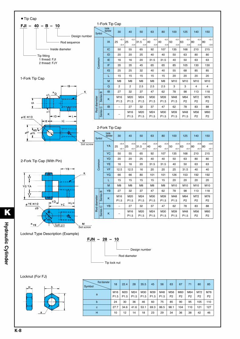
¡Tip Cap
1-Fork Tip Cap
10 – B – 40– FJI
Design number
Tip fitting 1 thread: FJI 2 thread: FJY
Rod sequence
Inside diameter
2-Fork Tip Cap (With Pin)
Locknut Type Description (Example)
Locknut (For FJ)
10 – 28 – FJN
Design number
Tip lock nut
Rod diameter
Insidediameter
Symbol 30 40 50 63 80 100 125 140 150
Com
mon
IA–0.1
25–0.4
–0.125
–0.4
–0.131.5
–0.4
–0.140
–0.4
–0.140
–0.4
–0.150
–0.4
–0.163
–0.4
–0.180
–0.6
–0.180
–0.6
IC 50 55 65 92 107 135 168 210 215
ID 20 20 25 40 40 50 63 80 80
IE 16 16 20 31.5 31.5 40 50 63 63
IF 35 35 45 65 65 85 105 130 130
IG 25 25 32 40 40 55 68 85 85
L 15 15 15 15 15 20 20 20 20
M M8 M8 M8 M8 M8 M10 M10 M10 M10
Q 2 2 2.5 2.5 2.5 3 3 4 4
Rod
dia
met
er
Ser
ies
B IB 27 32 37 47 62 78 98 113 118
KM16
P1.5
M20
P1.5
M24
P1.5
M30
P1.5
M39
P1.5
M48
P1.5
M64
P2
M72
P2
M76
P2S
erie
s C IB – 27 32 37 47 62 78 83 88
K –M16
P1.5
M20
P1.5
M24
P1.5
M30
P1.5
M39
P1.5
M48
P1.5
M56
P2
M60
P2
Insidediameter
Symbol30 40 50 63 80 100 125 140 150
Com
mon
YA+0.4
25+0.1
+0.4
25+0.1
+0.4
31.5+0.1
+0.4
40+0.1
+0.4
40+0.1
+0.4
50+0.1
+0.4
63+0.1
+0.6
80+0.1
+0.6
80+0.1
YC 50 55 65 92 107 135 168 210 215
YD 20 20 25 40 40 50 63 80 80
YE 16 16 20 31.5 31.5 40 50 63 63
YF 12.5 12.5 16 20 20 25 31.5 40 40
YG 66 66 80 101 101 126 153 192 192
L 15 15 15 15 15 20 20 20 20
M M8 M8 M8 M8 M8 M10 M10 M10 M10
Rod
dia
met
er
Ser
ies
B YB 27 32 37 47 62 78 98 113 118
KM16
P1.5
M20
P1.5
M24
P1.5
M30
P1.5
M39
P1.5
M48
P1.5
M64
P2
M72
P2
M76
P2
Ser
ies
C YB – 27 32 37 47 62 78 83 88
K –M16
P1.5
M20
P1.5
M24
P1.5
M30
P1.5
M39
P1.5
M48
P1.5
M56
P2
M60
P2
Rod diameter
Symbol18 22.4 28 35.5 45 56 63 67 71 80 85
aM16
P1.5
M20
P1.5
M24
P1.5
M30
P1.5
M39
P1.5
M48
P1.5
M56
P2
M60
P2
M64
P2
M72
P2
M76
P2
b 24 30 36 46 60 75 85 90 95 105 110
c 27.7 34.6 41.6 53.1 69.3 86.5 98.1 104 110 121 127
H 10 12 14 18 23 29 34 36 38 42 46
1-Fork Tip Cap
2-Fork Tip Cap
K Hydraulic Cylinder_E.q 03.11.20 2:01 PM Page 8