Electromotoric actuators for valves
12
CE1N4584en Building Technologies 2017-12-14 ACVATIX TM Electromotoric actuators for valves SAT.. Electromotoric actuators with 5.5 mm stroke and 300 N positioning force ● SAT31.. Operating voltage AC 230 V, 3-position control signal ● SAT61.. Operating voltage AC 24 V / DC 24 V, position signal DC 0...10 V / DC 4...20 mA / 0...1000 Ω ● For direct mounting on valves; no adjustments required ● Manual adjuster, position indicator and status indication per LED ● Optional functions with auxiliary switch
Transcript of Electromotoric actuators for valves
CE1N4584en Building Technologies2017-12-14
ACVATIX TM
Electromotoric actuators for valvesSAT..
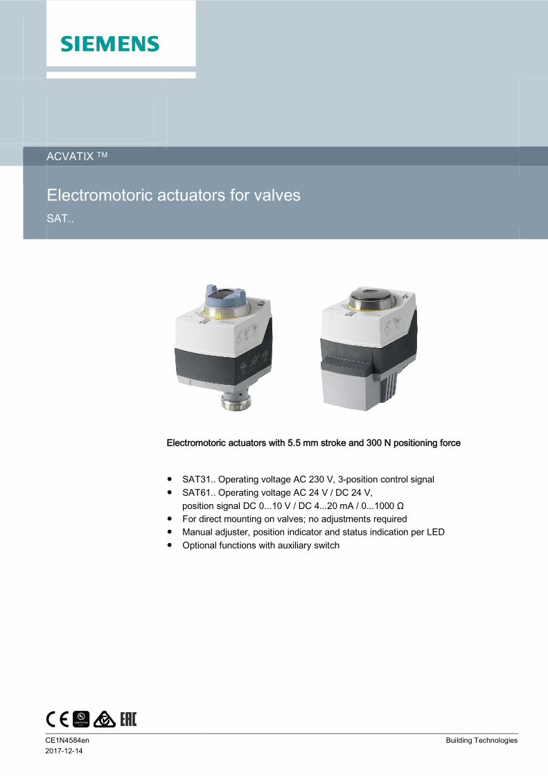
Electromotoric actuators with 5.5 mm stroke and 300 N positioning force
SAT31.. Operating voltage AC 230 V, 3-position control signal SAT61.. Operating voltage AC 24 V / DC 24 V, position signal DC 0...10 V / DC 4...20 mA / 0...1000 Ω For direct mounting on valves; no adjustments required Manual adjuster, position indicator and status indication per LED Optional functions with auxiliary switch
2Siemens AG CE1N4584enBuilding Technologies 2017-12-14
ApplicationFor the operation of Siemens 2-port and 3-port valves: Type series VVG549.. 5.5 mm strokeAs control or shutoff valves in heating and ventilation systems.
In conjunction with the ASK30 mounting kit, the former Landis & Gyr-valves with 4 mm or 5.5mm stroke can also be operated: X3i.., VVG45.., VXG45.., VXG46.., VVI51…
Functions
Function Description Type
3-position control A 3-position signal drives the actuator via connection terminals Y1 orY2. The desired position is transmitted to the valve.
SAT31..
Modulating control The modulating positioning signal drives the actuator steplessly. Thepositioning signal range (DC 0...10 V / DC 4...20 mA / 0...1000 Ω)corresponds in a linear manner to the positioning range (fullyclosed...fully open, or 0...100 % stroke).
SAT61..
Positioning signal andcharacteristic changeover
Setting the DIL switches.Factory setting SAT..:
∂ Characteristic curve: lin = linear (switch at "ON")∂ Positioning signal: DC 0...10 V (switch at "OFF")
Position feedback U Signal, returned to acquire the position via an input.
Calibration Conduct during initial commissioning. The actuator deploys to the topand bottom end position; measured values are saved.
Detection of valve seat Actuators have power-dependent seat detection. After calibration, theexact valve stroke is filed in the actuator’s memory.
Foreign body protection After detection of clogging, 3 attempts are made to overcome clogging.If the attempts made are unsuccessful, the actuator continues to followthe positioning signal within the restricted range only (LED continues toblink red).
Forced control Z(Z mode)
Forced control serves for overriding automatic mode and isimplemented in the structure.
Types
Type Stock no. Operatingvoltage
Positioningsignal
Powerconsumption
Posit.time
Spring returnfunction/time
Manualadjustment
Positionfeedback
Remark
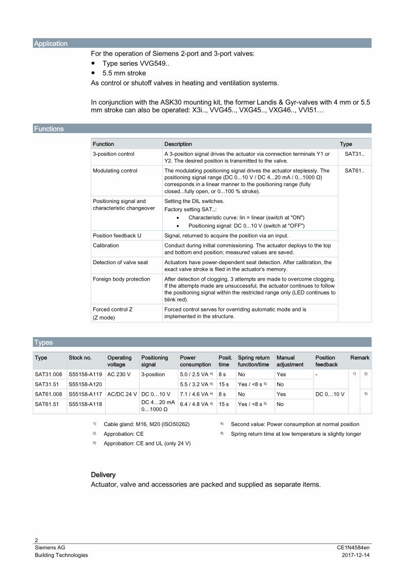
SAT31.008 S55158-A119 AC 230 V 3-position 5.0 / 2.5 VA 4) 8 s No Yes - 1) 2)
SAT31.51 S55158-A120 5.5 / 3.2 VA 4) 15 s Yes / <8 s 5) No
SAT61.008 S55158-A117 AC/DC 24 V DC 0…10 VDC 4…20 mA0…1000 Ω
7.1 / 4.6 VA 4) 8 s No Yes DC 0…10 V 3)
SAT61.51 S55158-A118 6.4 / 4.8 VA 4) 15 s Yes / <8 s 5) No
1) Cable gland: M16, M20 (ISO50262) 4) Second value: Power consumption at normal position2) Approbation: CE 5) Spring return time at low temperature is slightly longer3) Approbation: CE and UL (only 24 V)
DeliveryActuator, valve and accessories are packed and supplied as separate items.
3Siemens AG CE1N4584enBuilding Technologies 2017-12-14
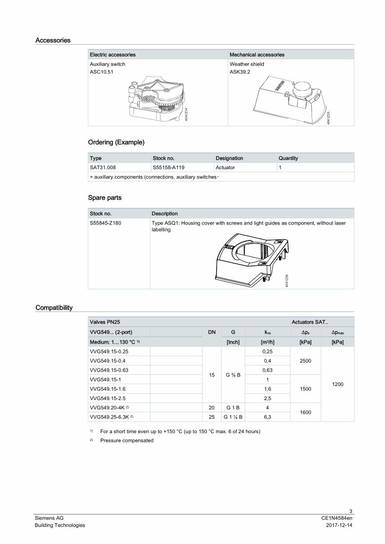
Accessories
Electric accessories Mechanical accessories
Auxiliary switchASC10.51
4041
Z14
Weather shieldASK39.2
4041
Z25
Ordering (Example)
Type Stock no. Designation Quantity
SAT31.008 S55158-A119 Actuator 1
+ auxiliary components (connections, auxiliary switches・
Spare parts
Stock no. Description
S55845-Z180 Type ASQ1: Housing cover with screws and light guides as component, without laserlabelling
4041
Z06
Compatibility
Valves PN25 Actuators SAT..
VVG549... (2-port) DN G kvs ∆ps ∆pmax
Medium: 1…130 °C 1) [Inch] [m3/h] [kPa] [kPa]
VVG549.15-0.25
15 G ¾ B
0,25
2500
1200
VVG549.15-0.4 0,4
VVG549.15-0.63 0,63
VVG549.15-1 1
1500VVG549.15-1.6 1,6
VVG549.15-2.5 2,5
VVG549.20-4K 2) 20 G 1 B 41600
VVG549.25-6.3K 2) 25 G 1 ¼ B 6,3
1) For a short time even up to +150 °C (up to 150 °C max. 6 of 24 hours)2) Pressure compensated
4Siemens AG CE1N4584enBuilding Technologies 2017-12-14
Product documentation
Name Topic Document ID
SAS.., SAT.. actuators for valvesBasic documentation
Detailed information about the SAS.. actuators CE1P4041en
Related documents such as environmental declarations, CE declarations, etc., can bedownloaded at the following Internet address:http://siemens.com/bt/download
Notes
Safety
CAUTION
National safety regulationsFailure to comply with national safety regulations may result in personal injury and propertydamage. Observe national provisions and comply with the appropriate safety regulations.
Engineering
SAT31..3-position actuators must have their own controller, see "Connection diagrams".
SAT61..Up to 10 actuators can drive in parallel on a controller output with a rating of 1 mA.Modulating actuators have an input impedance of 100 kΩ.
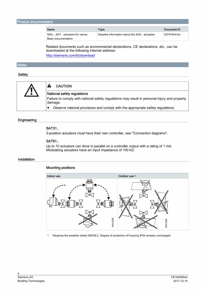
Installation
Mounting positions
Indoor use Outdoor use 1)
1) Requires the weather shield ASK39.2. Degree of protection of housing IP54 remains unchanged.
5Siemens AG CE1N4584enBuilding Technologies 2017-12-14
MaintenanceThe SAT.. actuators are maintenance-free.Mounting: Do not touch the valve coupling if the components (valve/pipes) are hot If necessary, disconnect electrical connections from the terminalsThe actuator must be correctly fitted to the valve before recommissioning.
Disposal
WARNING
Tensioned return springOpening the actuator housing can release the tensioned return spring resulting in flyingparts that may cause injury. Do not open the actuator body.
The device is considered electrical and electronic equipment for disposal interms of the applicable European Directive and may not be disposed of asdomestic garbage.
∂ Dispose of the device through channels provided for this purpose.∂ Comply with all local and currently applicable laws and regulations.
WarrantyTechnical data on specific applications are valid only together with Siemens products listedunder "Equipment combinations". Siemens rejects any and all warranties in the event thatthird-party products are used.
NoteWhen using the actuators in connection with valves of other manufacture, correct functioningmust be ensured by the user, and Siemens will assume no responsibility.
Technical data
Power supply SAS..
Operating voltage SAT31.. AC 230 V (±15 %)
SAT61.. AC 24 V ± 20 % / DC 24 V +20 % / -15 % or AC24 V class 2 (US)
Frequency 45…65 Hz
External supply line protection (EU) Fuse slow 6 A…10 A or fuse switch max. 13 A,release characteristic B,C,D per EN 60898power source with current limitation ofmax. 10 A
Power consumption at 50 Hz See "Type summary"; stem retracts/extends
Function data
Positioning time fornominal stroke
SAT..008 8 s
SAT..51 15 s
Positioning force 300 N
Nominal stroke 5.5 mm
Permissible medium valve fitted 1…130 °C
6Siemens AG CE1N4584enBuilding Technologies 2017-12-14
Function datatemperature for a short time even up to +150 °C
(up to 150 °C max. 6 of 24 hours)
Signal inputs
Y positioning signal SAT31.. 3-position
SAT61.. DC 0…10 V / DC 4…20 mA / 0…1000 Ω
SAT61.. (DC 0・10 V) Current draw ≤ 0.1 mA
Input impedance ≥ 100 kΩ
SAT61.. (DC 4・20 mA) Currentdraw
DC 4...20 mA ± 1 %
Input impedance ≤ 500 Ω
Parallel operation
SAT61.. ≤ 10 (depends on controller output)
Forced control Z
Positioning signal Z SAT61.. R = 0…1000 Ω, G, G0
R = 0…1000 Ω stroke proportional to R
Z connected to G max. stroke 100 %
Z connected to G0 min. stroke 0 %
Voltage Max. AC 24 V ±20 % /Max. DC 24 V +20 % / -15 %
Current draw ≤ 0.1 mA
Position feedback
U Voltage range SAT61.. DC 0…10 V
Load impedance > 10 kΩ res.
Load max. 1 mA
Connecting cable
Wire cross-sectionalareas
0.75…1.5 mm2, AWG 20…16 1)
Cable inputs SAT.. (EU) 1 entry Ø 16.4 mm (for M16)1 entry Ø 20.5 mm (for M20)Thread length max. 9mm
Degree of protection
Housing IP 54 per EN 60529
Insulation class As per EN 60730
Actuators SAT31.. AC 230 V II
Actuators SAT61.. AC/DC 24 V III
Environmental conditions
Operation IEC 60721-3-3
Climatic conditions class 3K5
Mounting location Indoors, outdoors 2)
Temperature general -5…55 °C
Humidity (noncondensing) 5...95 % r. h.
Transport IEC 60721-3-2
7Siemens AG CE1N4584enBuilding Technologies 2017-12-14
Environmental conditions
Climatic conditions class 2K3
Temperature -25…70 °C
Humidity <95 % r. F.
Storage IEC 60721-3-1
Temperature -15…55 °C
Humidity 5...95 % r. h.
Standards
Product standard EN60730-x
Electromagnetic compatibility (field of use) For residential, commercial and industrialenvironments
EU conformity (CE) CE1T4584xx 3)
(8000073403)
RCM conformity CE1T4584en_C1 3)
(8000069922)
UL, cUL AC / DC 24 V UL 873 http://ul.com/database
EAC conformity Eurasia conformity for all SAT variants
Environmental compatibility
Environmental Declaration CE1E4584encontains data on environmental-compatibleproduct design and assessment (RoHScompliance, compositions, packaging,environmental benefits and disposal)
Dimensions / Weight
Refer to “Dimensions”
Accessories 4)
Auxiliary switchASC10.51
Switching capacity AC 24...230 V, 6 (2) A, potential free
External supply line protection See section power supply
US Installation, UL & cUL AC 24 V class 2, 5 A general purpose
1) AWG = American wire gauge.Wire cross-sectional areas and fuses have to be matched, which is the responsibility of the planner/installer.Observe standard on protection measures – Protection against overcurrent:IEC 60364-4-43:2008 or German adoption HD 60364-4-43:2010.
2) Outdoors use only with weather shield ASK39.2, degree of protection of housing IP 54 remains unchanged3) The documents can be downloaded at the Internet address, see Section 'Product documentation'.4)
UL recognized component
8Siemens AG CE1N4584enBuilding Technologies 2017-12-14
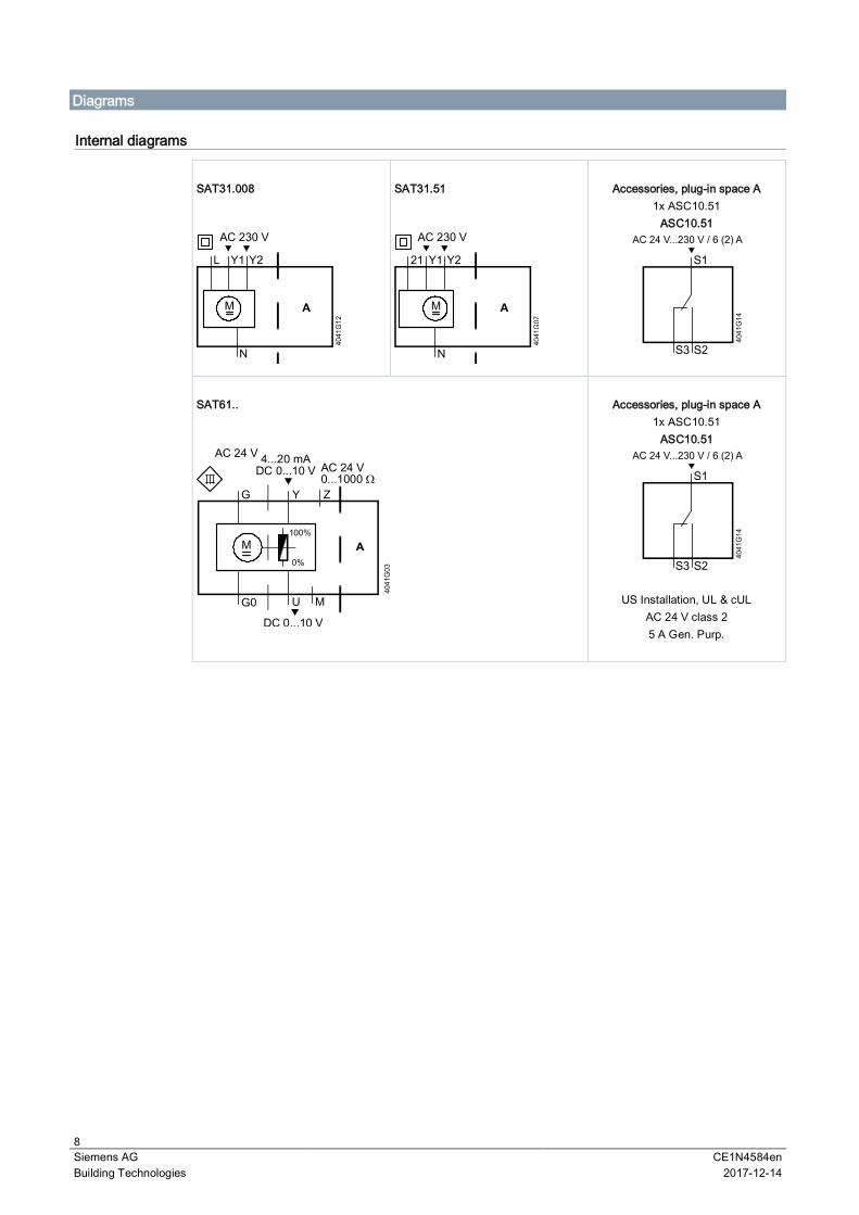
Diagrams
Internal diagrams
SAT31.008
AC 230 V
M
SAT31.51
AC 230 V
M
Accessories, plug-in space A1x ASC10.51
ASC10.51
SAT61..
M100%
0%
DC 0...10 V
G0 U
G Y
AC 24 V 4...20 mADC 0...10 V
M
Z
AC 24 V0...1000 ς
Accessories, plug-in space A1x ASC10.51
ASC10.51
US Installation, UL & cULAC 24 V class 25 A Gen. Purp.
9Siemens AG CE1N4584enBuilding Technologies 2017-12-14
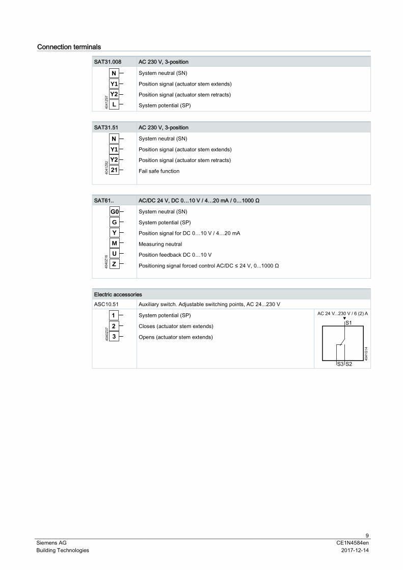
Connection terminals
SAT31.008 AC 230 V, 3-position
Y1
System neutral (SN)
Position signal (actuator stem extends)
Position signal (actuator stem retracts)
System potential (SP)
SAT31.51 AC 230 V, 3-position
Y1
System neutral (SN)
Position signal (actuator stem extends)
Position signal (actuator stem retracts)
Fail safe function
SAT61.. AC/DC 24 V, DC 0…10 V / 4…20 mA / 0…1000 Ω
M
G
System neutral (SN)
System potential (SP)
Position signal for DC 0…10 V / 4…20 mA
Measuring neutral
Position feedback DC 0…10 V
Positioning signal forced control AC/DC ≤ 24 V, 0...1000 Ω
Electric accessories
ASC10.51 Auxiliary switch. Adjustable switching points, AC 24...230 V
System potential (SP)
Closes (actuator stem extends)
Opens (actuator stem extends)
10Siemens AG CE1N4584enBuilding Technologies 2017-12-14
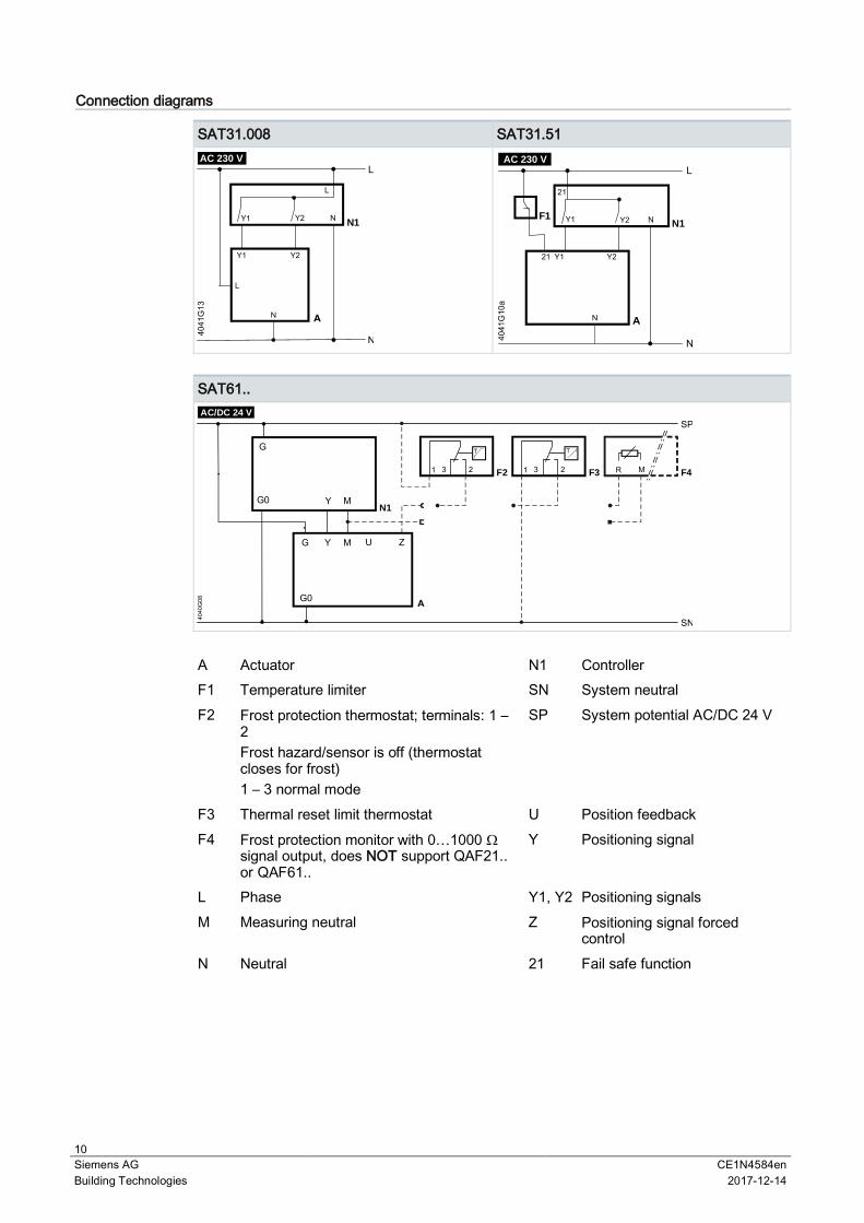
Connection diagrams
SAT31.008 SAT31.51
L
Y1 Y2 N1
L
N
N
AC 230 V
L
N1
N
LAC 230 V
Y1 Y2
21
F1
SAT61..
G
N1
G M U
SN
F2
M
AC/DC 24 V
Z
1 3 2 F31 3 2 F4R M
SP
A Actuator N1 ControllerF1 Temperature limiter SN System neutralF2 Frost protection thermostat; terminals: 1 –
2Frost hazard/sensor is off (thermostatcloses for frost)1 – 3 normal mode
SP System potential AC/DC 24 V
F3 Thermal reset limit thermostat U Position feedbackF4 Frost protection monitor with 0…1000 Ω
signal output, does NOT support QAF21..or QAF61..
Y Positioning signal
L Phase Y1, Y2 Positioning signalsM Measuring neutral Z Positioning signal forced
controlN Neutral 21 Fail safe function
11Siemens AG CE1N4584enBuilding Technologies 2017-12-14
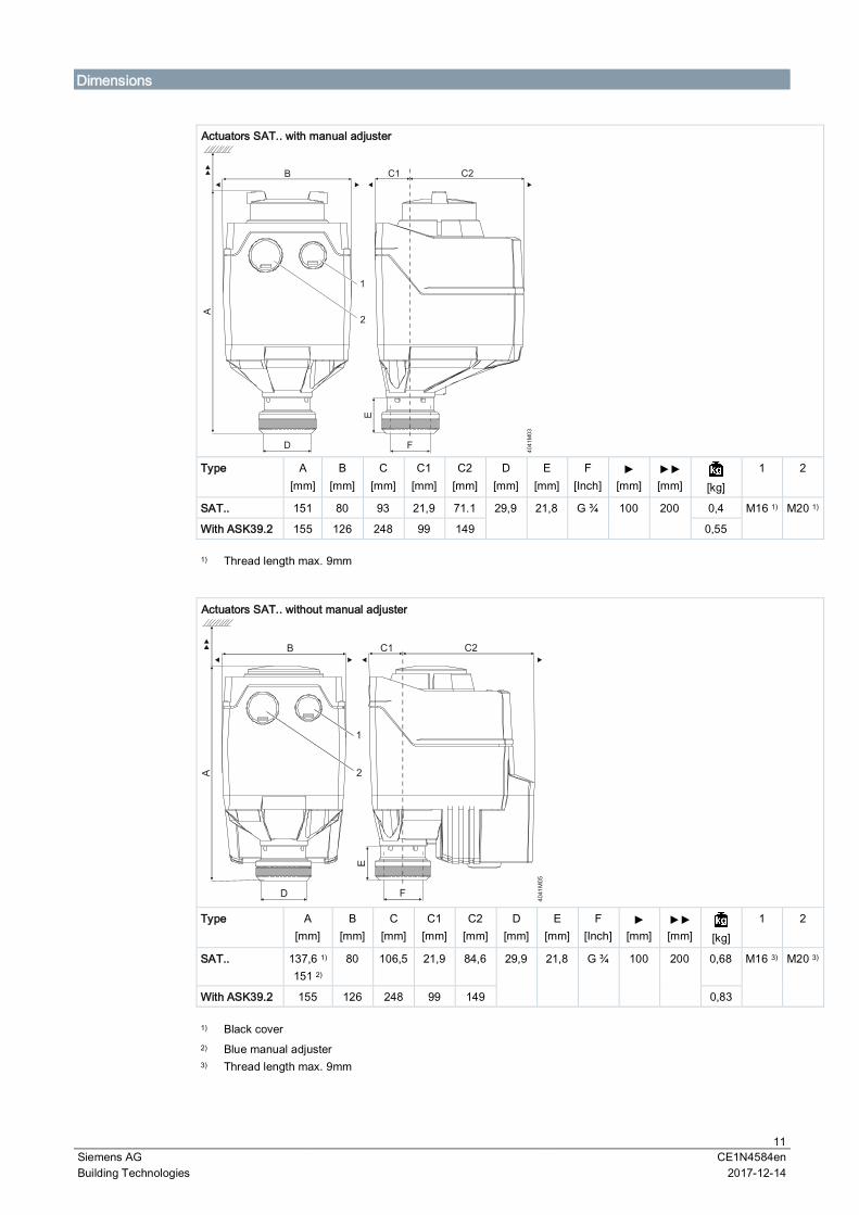
Dimensions
Actuators SAT.. with manual adjuster
Type A[mm]
B[mm]
C[mm]
C1[mm]
C2[mm]
D[mm]
E[mm]
F[Inch] [mm] [mm] [kg]
1 2
SAT.. 151 80 93 21,9 71.1 29,9 21,8 G ¾ 100 200 0,4 M16 1) M20 1)
With ASK39.2 155 126 248 99 149 0,55
1) Thread length max. 9mm
Actuators SAT.. without manual adjuster
Type A[mm]
B[mm]
C[mm]
C1[mm]
C2[mm]
D[mm]
E[mm]
F[Inch] [mm] [mm] [kg]
1 2
SAT.. 137,6 1)
151 2)
80 106,5 21,9 84,6 29,9 21,8 G ¾ 100 200 0,68 M16 3) M20 3)
With ASK39.2 155 126 248 99 149 0,83
1) Black cover2)
3)
Blue manual adjusterThread length max. 9mm
12Siemens AG CE1N4584enBuilding Technologies 2017-12-14
Issued bySiemens Switzerland LtdBuilding Technologies DivisionInternational HeadquartersGubelstrasse 22CH-6301 ZugTel. +41 58-724 24 24www.siemens.com/buildingtechnologies
© Siemens Switzerland Ltd, 2015Technical specifications and availability subject to change without notice.
Document ID CE1N4584enEdition 2017-12-14
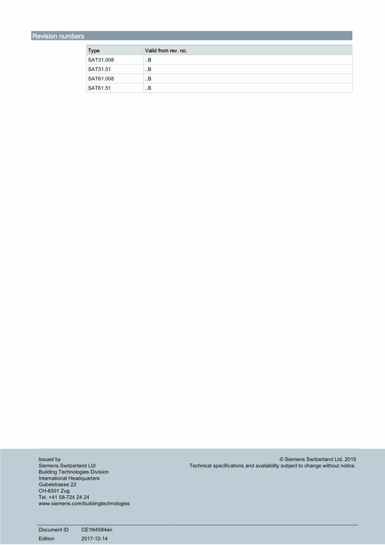
Revision numbers
Type Valid from rev. no.
SAT31.008 ..B
SAT31.51 ..B
SAT61.008 ..B
SAT61.51 ..B