FPGA Based Controller for High-Speed Permanent Magnet ...
6
Φ Abstract -- This paper presents the development of a controller for a high-speed permanent magnet synchronous motor based on Field Programmable Gate Arrays (FPGA). The controller was tested on a motor with maximal speed 42000 RPM, nominal speed 25000 RPM, nominal torque 1,2 Nm and nominal current 11 A. The novel controller design shows much promise to handle field-oriented control for higher speeds than previously available with digital signal processors. According to our tests, the controller is able to handle speeds at least 40x higher. Index Terms-- High-speed motors, Permanent magnet motors I. NOMENCLATURE v x (t) – instantaneous voltage value in phase x [V] R s – stator resistance [Ω] Ψ – flux linkage [Wb] i x – instantaneous current value in phase x [A] φ - rotor angle [rad] L – inductance ω – electrical speed [rad/s] ω m –mechanical speed [rad/s] T e – electrical torque [Nm] p p - number of pole-pairs [-] II. INTRODUCTION HE design and applications of high-speed motors are becoming a demanded topic in the industry. They can be used as high-speed spindles, microturbine power generators, blowers, pumps, hybrid electric vehicles, turbo molecular pumps, electrically driven turbo-compressors etc. [1] - [4]. For systems with high dynamics and feedback control, Field-Oriented Control (FOC) needs to be used. Traditional permanent magnet synchronous motor (PMSM) controller systems are based on digital signal processors (DSP). For systems with lower dynamic requirements, V/f control can be easily employed [5]-[7]. Those systems can be easily driven up to speeds of several hundredth thousand RPM. When FOC is used, the situation changes quickly. The algorithm requires much more computational power and so the maximal speed is usually limited to much lower speeds, Φ This work was supported in part by the Czech ministry of education, youth and sport grant no. MSM6840770035 “The Development of Environmental - Friendly Decentralized Power Engineering”, internal CTU Grant "Development of measuring, simulation and experimental methods with focus on non-traditional energy source" and support of EU Regional Development Fund in OP R&D for Innovations (OP VaVpI) and Ministry for Education, Czech Republic, project # CZ.1.05/2.1.00/03.0125 Acquisition of Technology for Vehicle Center of Sustainable Mobility. This support is gratefully acknowledged. M. Novak is with Department of Instrumentation and Control Engineering, Faculty of Mechanical Engineering, Czech Technical University in Prague, Prague, Czech republic (e-mail: Martin.Novak2 @fs.cvut.cz). around 70 000 RPM [8]. For higher speeds and by maintaining the advantages of FOC, we have developed a novel FPGA based controller for high-speed permanent magnet motors. It removes the limit presented by the insufficient computational power of a DSP and allows increasing the available speed by a factor at least 40. III. CONTROL OF PMSM As the principle of Field-Oriented Control of PMSM is well known, it will be stated only very briefly. Vector control in principle controls both the magnitude and phase of the controlled currents. This allows to decouple torque and flux (both are functions of current and frequency) and provides faster transient responses [9]. This control structure, by achieving a very accurate steady state and transient control, leads to high dynamic performance in terms of response times and power conversion [10]. The principle of field oriented control is in recalculation of currents to an equivalent 2 phase machine with direct (d) and quadrature (q) axes for stator and rotor. The input values for FOC are torque component (aligned with q co-ordinate) and flux (aligned with d co-ordinate). The electrical PMSM model in dq coordinate system is q q sq q dd m di v Ri L Li dt ϖ ψ ϖ = + + + (1) d d sd d qq di v Ri L Li dt ϖ = + - (2) The electric torque produced by the PMSM is ( 29 3 2 e p mq d q dq T p i L L ii ψ = + - (3) The i d and i q currents in (1) - (3) are controlled by two independent PI controllers either with or without decoupling. It is well known, that the required Park and Clarke transformations need information about instantaneous rotor angle. This can be obtained either with a position sensor or estimated with a sensor-less approach. The general block diagram of such controller system either for DSP or FPGA implementation is shown in Fig. 1. IV. DESCRIPTION OF THE EXPERIMENTAL SYSTEM The described project was about building an experimental setup and testing a high-speed power generator. It is one of the principles with good perspectives for micro energy generation with a micro turbine. This solution uses a miniature gas powered turbine powered e.g. with natural gas, biogas, gasoline etc. The turbine is coupled to a generator providing electrical energy. The advantages over a classical piston based generator are significantly higher efficiency and smaller dimensions for the same output power. They are also less sensitive for fuel impurities. FPGA Based Controller for High-Speed Permanent Magnet Synchronous Motor M. Novak T
Transcript of FPGA Based Controller for High-Speed Permanent Magnet ...
ΦΦΦΦAbstract -- This paper presents the development of a controller for a high-speed permanent magnet synchronous motor based on Field Programmable Gate Arrays (FPGA). The controller was tested on a motor with maximal speed 42000 RPM, nominal speed 25000 RPM, nominal torque 1,2 Nm and nominal current 11 A. The novel controller design shows much promise to handle field-oriented control for higher speeds than previously available with digital signal processors. According to our tests, the controller is able to handle speeds at least 40x higher.
Index Terms-- High-speed motors, Permanent magnet motors
I. NOMENCLATURE
vx(t) – instantaneous voltage value in phase x [V] Rs – stator resistance [Ω] Ψ – flux linkage [Wb] ix – instantaneous current value in phase x [A] φ - rotor angle [rad] L – inductance ω – electrical speed [rad/s] ωm –mechanical speed [rad/s] Te – electrical torque [Nm] pp - number of pole-pairs [-]
II. INTRODUCTION
HE design and applications of high-speed motors are becoming a demanded topic in the industry. They can be used as high-speed spindles, microturbine power
generators, blowers, pumps, hybrid electric vehicles, turbo molecular pumps, electrically driven turbo-compressors etc. [1] - [4]. For systems with high dynamics and feedback control, Field-Oriented Control (FOC) needs to be used. Traditional permanent magnet synchronous motor (PMSM) controller systems are based on digital signal processors (DSP). For systems with lower dynamic requirements, V/f control can be easily employed [5]-[7]. Those systems can be easily driven up to speeds of several hundredth thousand RPM. When FOC is used, the situation changes quickly. The algorithm requires much more computational power and so the maximal speed is usually limited to much lower speeds,
ΦThis work was supported in part by the Czech ministry of education,
youth and sport grant no. MSM6840770035 “The Development of Environmental - Friendly Decentralized Power Engineering”, internal CTU Grant "Development of measuring, simulation and experimental methods with focus on non-traditional energy source" and support of EU Regional Development Fund in OP R&D for Innovations (OP VaVpI) and Ministry for Education, Czech Republic, project # CZ.1.05/2.1.00/03.0125 Acquisition of Technology for Vehicle Center of Sustainable Mobility. This support is gratefully acknowledged.
M. Novak is with Department of Instrumentation and Control Engineering, Faculty of Mechanical Engineering, Czech Technical University in Prague, Prague, Czech republic (e-mail: Martin.Novak2 @fs.cvut.cz).
around 70 000 RPM [8]. For higher speeds and by maintaining the advantages of FOC, we have developed a novel FPGA based controller for high-speed permanent magnet motors. It removes the limit presented by the insufficient computational power of a DSP and allows increasing the available speed by a factor at least 40.
III. CONTROL OF PMSM
As the principle of Field-Oriented Control of PMSM is well known, it will be stated only very briefly. Vector control in principle controls both the magnitude and phase of the controlled currents. This allows to decouple torque and flux (both are functions of current and frequency) and provides faster transient responses [9]. This control structure, by achieving a very accurate steady state and transient control, leads to high dynamic performance in terms of response times and power conversion [10]. The principle of field oriented control is in recalculation of currents to an equivalent 2 phase machine with direct (d) and quadrature (q) axes for stator and rotor. The input values for FOC are torque component (aligned with q co-ordinate) and flux (aligned with d co-ordinate).
The electrical PMSM model in dq coordinate system is
qq s q q d d m
div R i L L i
dtω ψω= + + + (1)
dd s d d q q
div R i L L i
dtω= + − (2)
The electric torque produced by the PMSM is
( )3
2e p m q d q d qT p i L L i iψ = + − (3)
The id and iq currents in (1) - (3) are controlled by two independent PI controllers either with or without decoupling. It is well known, that the required Park and Clarke transformations need information about instantaneous rotor angle. This can be obtained either with a position sensor or estimated with a sensor-less approach.
The general block diagram of such controller system either for DSP or FPGA implementation is shown in Fig. 1.
IV. DESCRIPTION OF THE EXPERIMENTAL SYSTEM
The described project was about building an experimental setup and testing a high-speed power generator. It is one of the principles with good perspectives for micro energy generation with a micro turbine. This solution uses a miniature gas powered turbine powered e.g. with natural gas, biogas, gasoline etc. The turbine is coupled to a generator providing electrical energy. The advantages over a classical piston based generator are significantly higher efficiency and smaller dimensions for the same output power. They are also less sensitive for fuel impurities.
FPGA Based Controller for High-Speed Permanent Magnet Synchronous Motor
M. Novak
T
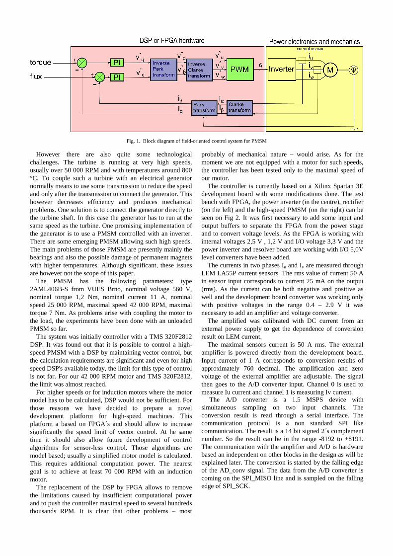
Fig. 1. Block diagram of field-oriented control system for PMSM
However there are also quite some technological challenges. The turbine is running at very high speeds, usually over 50 000 RPM and with temperatures around 800 °C. To couple such a turbine with an electrical generator normally means to use some transmission to reduce the speed and only after the transmission to connect the generator. This however decreases efficiency and produces mechanical problems. One solution is to connect the generator directly to the turbine shaft. In this case the generator has to run at the same speed as the turbine. One promising implementation of the generator is to use a PMSM controlled with an inverter. There are some emerging PMSM allowing such high speeds. The main problems of those PMSM are presently mainly the bearings and also the possible damage of permanent magnets with higher temperatures. Although significant, these issues are however not the scope of this paper.
The PMSM has the following parameters: type 2AML406B-S from VUES Brno, nominal voltage 560 V, nominal torque 1,2 Nm, nominal current 11 A, nominal speed 25 000 RPM, maximal speed 42 000 RPM, maximal torque 7 Nm. As problems arise with coupling the motor to the load, the experiments have been done with an unloaded PMSM so far.
The system was initially controller with a TMS 320F2812 DSP. It was found out that it is possible to control a high-speed PMSM with a DSP by maintaining vector control, but the calculation requirements are significant and even for high speed DSP's available today, the limit for this type of control is not far. For our 42 000 RPM motor and TMS 320F2812, the limit was almost reached.
For higher speeds or for induction motors where the motor model has to be calculated, DSP would not be sufficient. For those reasons we have decided to prepare a novel development platform for high-speed machines. This platform a based on FPGA´s and should allow to increase significantly the speed limit of vector control. At he same time it should also allow future development of control algorithms for sensor-less control. Those algorithms are model based; usually a simplified motor model is calculated. This requires additional computation power. The nearest goal is to achieve at least 70 000 RPM with an induction motor.
The replacement of the DSP by FPGA allows to remove the limitations caused by insufficient computational power and to push the controller maximal speed to several hundreds thousands RPM. It is clear that other problems – most
probably of mechanical nature – would arise. As for the moment we are not equipped with a motor for such speeds, the controller has been tested only to the maximal speed of our motor.
The controller is currently based on a Xilinx Spartan 3E development board with some modifications done. The test bench with FPGA, the power inverter (in the centre), rectifier (on the left) and the high-speed PMSM (on the right) can be seen on Fig 2. It was first necessary to add some input and output buffers to separate the FPGA from the power stage and to convert voltage levels. As the FPGA is working with internal voltages 2,5 V , 1,2 V and I/O voltage 3,3 V and the power inverter and resolver board are working with I/O 5,0V level converters have been added.
The currents in two phases Iu and Iv are measured through LEM LA55P current sensors. The rms value of current 50 A in sensor input corresponds to current 25 mA on the output (rms). As the current can be both negative and positive as well and the development board converter was working only with positive voltages in the range 0.4 – 2.9 V it was necessary to add an amplifier and voltage converter.
The amplified was calibrated with DC current from an external power supply to get the dependence of conversion result on LEM current.
The maximal sensors current is 50 A rms. The external amplifier is powered directly from the development board. Input current of 1 A corresponds to conversion results of approximately 760 decimal. The amplification and zero voltage of the external amplifier are adjustable. The signal then goes to the A/D converter input. Channel 0 is used to measure Iu current and channel 1 is measuring Iv current.
The A/D converter is a 1.5 MSPS device with simultaneous sampling on two input channels. The conversion result is read through a serial interface. The communication protocol is a non standard SPI like communication. The result is a 14 bit signed 2´s complement number. So the result can be in the range -8192 to +8191. The communication with the amplifier and A/D is hardware based an independent on other blocks in the design as will be explained later. The conversion is started by the falling edge of the AD_conv signal. The data from the A/D converter is coming on the SPI_MISO line and is sampled on the falling edge of SPI_SCK.
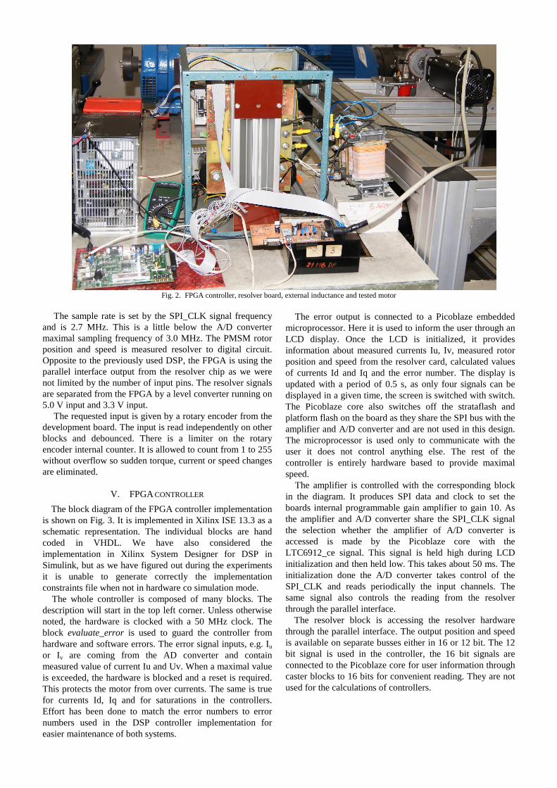
Fig. 2. FPGA controller, resolver board, external inductance and tested motor
The sample rate is set by the SPI_CLK signal frequency
and is 2.7 MHz. This is a little below the A/D converter maximal sampling frequency of 3.0 MHz. The PMSM rotor position and speed is measured resolver to digital circuit. Opposite to the previously used DSP, the FPGA is using the parallel interface output from the resolver chip as we were not limited by the number of input pins. The resolver signals are separated from the FPGA by a level converter running on 5.0 V input and 3.3 V input.
The requested input is given by a rotary encoder from the development board. The input is read independently on other blocks and debounced. There is a limiter on the rotary encoder internal counter. It is allowed to count from 1 to 255 without overflow so sudden torque, current or speed changes are eliminated.
V. FPGA CONTROLLER
The block diagram of the FPGA controller implementation is shown on Fig. 3. It is implemented in Xilinx ISE 13.3 as a schematic representation. The individual blocks are hand coded in VHDL. We have also considered the implementation in Xilinx System Designer for DSP in Simulink, but as we have figured out during the experiments it is unable to generate correctly the implementation constraints file when not in hardware co simulation mode.
The whole controller is composed of many blocks. The description will start in the top left corner. Unless otherwise noted, the hardware is clocked with a 50 MHz clock. The block evaluate_error is used to guard the controller from hardware and software errors. The error signal inputs, e.g. Iu or Iv are coming from the AD converter and contain measured value of current Iu and Uv. When a maximal value is exceeded, the hardware is blocked and a reset is required. This protects the motor from over currents. The same is true for currents Id, Iq and for saturations in the controllers. Effort has been done to match the error numbers to error numbers used in the DSP controller implementation for easier maintenance of both systems.
The error output is connected to a Picoblaze embedded microprocessor. Here it is used to inform the user through an LCD display. Once the LCD is initialized, it provides information about measured currents Iu, Iv, measured rotor position and speed from the resolver card, calculated values of currents Id and Iq and the error number. The display is updated with a period of 0.5 s, as only four signals can be displayed in a given time, the screen is switched with switch. The Picoblaze core also switches off the strataflash and platform flash on the board as they share the SPI bus with the amplifier and A/D converter and are not used in this design. The microprocessor is used only to communicate with the user it does not control anything else. The rest of the controller is entirely hardware based to provide maximal speed.
The amplifier is controlled with the corresponding block in the diagram. It produces SPI data and clock to set the boards internal programmable gain amplifier to gain 10. As the amplifier and A/D converter share the SPI_CLK signal the selection whether the amplifier of A/D converter is accessed is made by the Picoblaze core with the LTC6912_ce signal. This signal is held high during LCD initialization and then held low. This takes about 50 ms. The initialization done the A/D converter takes control of the SPI_CLK and reads periodically the input channels. The same signal also controls the reading from the resolver through the parallel interface.
The resolver block is accessing the resolver hardware through the parallel interface. The output position and speed is available on separate busses either in 16 or 12 bit. The 12 bit signal is used in the controller, the 16 bit signals are connected to the Picoblaze core for user information through caster blocks to 16 bits for convenient reading. They are not used for the calculations of controllers.
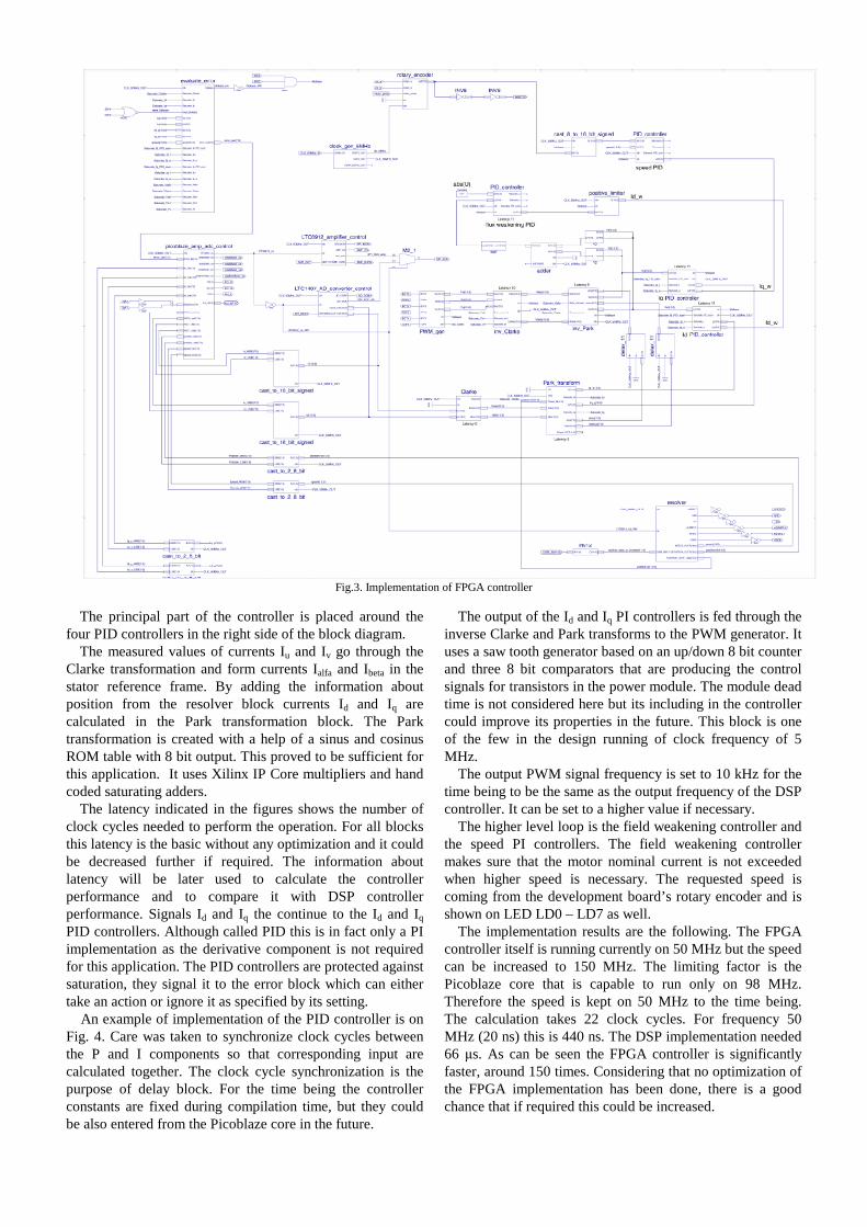
Fig.3. Implementation of FPGA controller
The principal part of the controller is placed around the four PID controllers in the right side of the block diagram.
The measured values of currents Iu and Iv go through the Clarke transformation and form currents Ialfa and Ibeta in the stator reference frame. By adding the information about position from the resolver block currents Id and Iq are calculated in the Park transformation block. The Park transformation is created with a help of a sinus and cosinus ROM table with 8 bit output. This proved to be sufficient for this application. It uses Xilinx IP Core multipliers and hand coded saturating adders.
The latency indicated in the figures shows the number of clock cycles needed to perform the operation. For all blocks this latency is the basic without any optimization and it could be decreased further if required. The information about latency will be later used to calculate the controller performance and to compare it with DSP controller performance. Signals Id and Iq the continue to the Id and Iq PID controllers. Although called PID this is in fact only a PI implementation as the derivative component is not required for this application. The PID controllers are protected against saturation, they signal it to the error block which can either take an action or ignore it as specified by its setting.
An example of implementation of the PID controller is on Fig. 4. Care was taken to synchronize clock cycles between the P and I components so that corresponding input are calculated together. The clock cycle synchronization is the purpose of delay block. For the time being the controller constants are fixed during compilation time, but they could be also entered from the Picoblaze core in the future.
The output of the Id and Iq PI controllers is fed through the inverse Clarke and Park transforms to the PWM generator. It uses a saw tooth generator based on an up/down 8 bit counter and three 8 bit comparators that are producing the control signals for transistors in the power module. The module dead time is not considered here but its including in the controller could improve its properties in the future. This block is one of the few in the design running of clock frequency of 5 MHz.
The output PWM signal frequency is set to 10 kHz for the time being to be the same as the output frequency of the DSP controller. It can be set to a higher value if necessary.
The higher level loop is the field weakening controller and the speed PI controllers. The field weakening controller makes sure that the motor nominal current is not exceeded when higher speed is necessary. The requested speed is coming from the development board’s rotary encoder and is shown on LED LD0 – LD7 as well.
The implementation results are the following. The FPGA controller itself is running currently on 50 MHz but the speed can be increased to 150 MHz. The limiting factor is the Picoblaze core that is capable to run only on 98 MHz. Therefore the speed is kept on 50 MHz to the time being. The calculation takes 22 clock cycles. For frequency 50 MHz (20 ns) this is 440 ns. The DSP implementation needed 66 µs. As can be seen the FPGA controller is significantly faster, around 150 times. Considering that no optimization of the FPGA implementation has been done, there is a good chance that if required this could be increased.
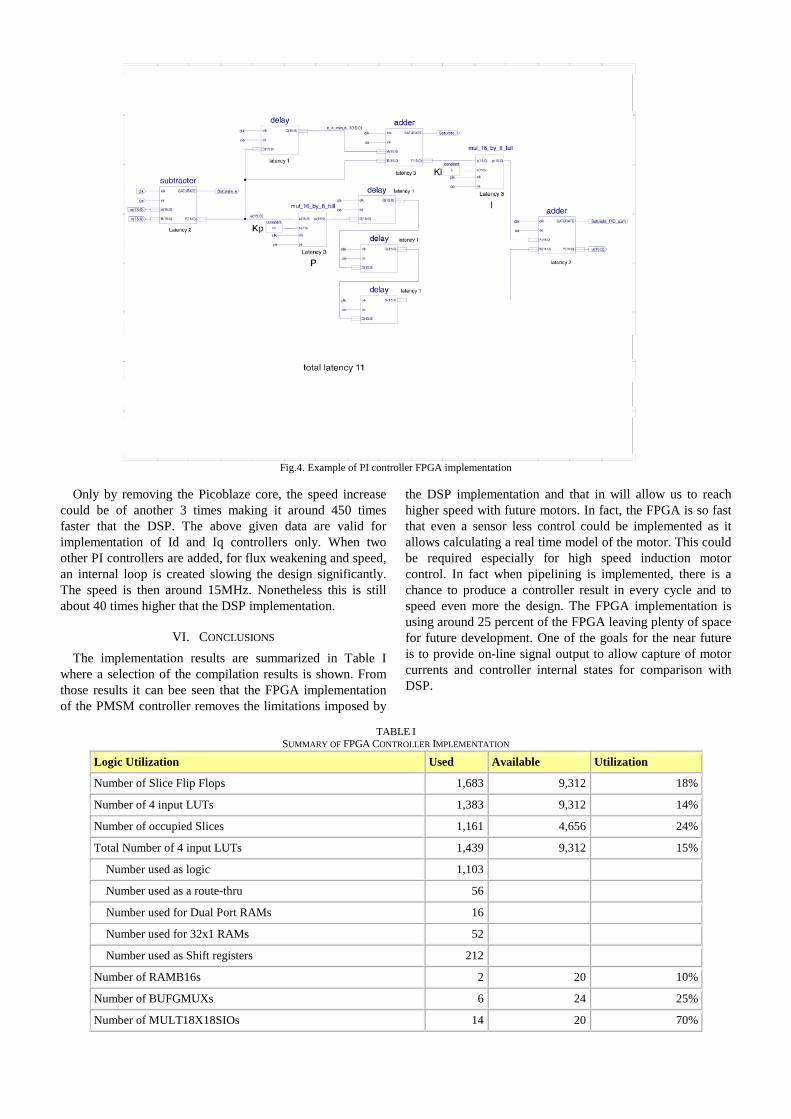
Fig.4. Example of PI controller FPGA implementation
Only by removing the Picoblaze core, the speed increase could be of another 3 times making it around 450 times faster that the DSP. The above given data are valid for implementation of Id and Iq controllers only. When two other PI controllers are added, for flux weakening and speed, an internal loop is created slowing the design significantly. The speed is then around 15MHz. Nonetheless this is still about 40 times higher that the DSP implementation.
VI. CONCLUSIONS
The implementation results are summarized in Table I where a selection of the compilation results is shown. From those results it can bee seen that the FPGA implementation of the PMSM controller removes the limitations imposed by
the DSP implementation and that in will allow us to reach higher speed with future motors. In fact, the FPGA is so fast that even a sensor less control could be implemented as it allows calculating a real time model of the motor. This could be required especially for high speed induction motor control. In fact when pipelining is implemented, there is a chance to produce a controller result in every cycle and to speed even more the design. The FPGA implementation is using around 25 percent of the FPGA leaving plenty of space for future development. One of the goals for the near future is to provide on-line signal output to allow capture of motor currents and controller internal states for comparison with DSP.
TABLE I SUMMARY OF FPGA CONTROLLER IMPLEMENTATION
Logic Utilization Used Available Utilization
Number of Slice Flip Flops 1,683 9,312 18%
Number of 4 input LUTs 1,383 9,312 14%
Number of occupied Slices 1,161 4,656 24%
Total Number of 4 input LUTs 1,439 9,312 15%
Number used as logic 1,103
Number used as a route-thru 56
Number used for Dual Port RAMs 16
Number used for 32x1 RAMs 52
Number used as Shift registers 212
Number of RAMB16s 2 20 10%
Number of BUFGMUXs 6 24 25%
Number of MULT18X18SIOs 14 20 70%
VII. REFERENCES [1] Chunyuan B. - Shuangyan R. - Liangyu M.: Sensorless DTC of Super
High-speed PMSM, Proceeding of the IEEE International Conference on Automation and Logistics, August 18-21, 2007, Jinan, China,1-4244-1531-4/07
[2] Rahman M.A. - Chiba A. - Fukao T.: Super High Speed Electrical Machines - Summary, In. Extended Sumary for IEEE-PES Meeting at Denver 2004 Panel Session on Super High Speed Drive, ISBN 0-7803-8465-2, DOI.: 10.1109/PES.2004.1373062
[3] Anh J.B. - Jeong Y.H. - Kang D.H. - Park J.H.: Development of High Speed PMSM for Distributed Generation Using Microturbine, In proceedings of 30th Annual Conference of the IEEE Industrial Electronics Society, November 2004, Busan, Korea, ISBN 0-7803-8730-9, DOI.: 10.1109/IECON.2004.1432151
[4] MiTi Developments, Oil-free, Motorized, Automotive Fuel Cell Air Compressor/Expander System, Mohawk Innovative Technology, Vol. 25, November 2005, Available on < http://www.miti.cc/newsletters/25_Motorized_Fuel_Cell_Air_Compressor.pdf > [accessed 5.1.2012]
[5] Zhao L. - Ham Ch. H. - Wu T. X - Zheng L. - Seuigneur H.P. - Sundaraml B. - Kapat J. - Vaidya J. - Chow L.: Development of A Super High-Speed Permanent Magnet Synchronous Motor (PMSM) Controller and Analysis of The Experimental Results, Journal of Systemics, Cybernetics and Informatics, Volume 3 - Number 1, ISSN 1690-4524
[6] Zheng L. - Wu X. T. - Acharya D. - Sundaram K. B. - Vaidya J. - Zhao L. - Zhou L. - Ham Ch. H. - Arakere N. - Kapat J. - Chow L.: Design of a Superhigh-Speed Cryogenic Permanent Magnet Synchronous Motor, IEEE Transactions on magnetics, Vol. 41, No 10. October 2005
[7] Zhao L. - Ham Ch. H. - Wu T. X. - Zheng L. - Sundaram K. B. - Kapat J. - Chow L.: A DSP Based Super High-Speed PMSM Controller Development and Optimization, 2004 IEEE 11th Digital Signal Processing Workshop & IEEE Signal Procesing Education Workshop, 0-7803-8434-2/04
[8] Bae B-H. - Sul S-K. - Kwon J-H. - Shin J-S: Implementation of Sensorless Vector Control for Super-High Speed PMSM of Turbo-Compressor, In: IEEE Transactions on Industry Applications, Volume : 39(3), Page(s) : 811-818, 05/2003
[9] An Introduction to Vector Control of AC Motors Using the V850 [online], November, 2002, Vol.12, No. U16483EE1V0AN00, Available on <www2.renesas.eu/_pdf/U16483EE1V0AN00.PDF> [accessed 6.12.2011]
[10] Field Orientated Control of 3-Phase AC-Motors [online], February, 1998, Available on <www.ti.com/lit/an/bpra073/bpra073.pdf> [accessed 6.12.2011]
![Material Magnet [Compatibility Mode]](https://static.fdocument.org/doc/165x107/5885bc341a28ab1c198c4f13/material-magnet-compatibility-mode.jpg)