FINITE ELEMENT ANALYSIS AND OPTIMIZATION OF...
13
http://www.iaeme.com/IJMET/index.asp 48 [email protected] International Journal of Mechanical Engineering and Technology (IJMET) Volume 7, Issue 4, July–Aug 2016, pp.48–60, Article ID: IJMET_07_04_006 Available online at http://www.iaeme.com/ijmet/issues.asp?JType=IJMET&VType=7&IType=4 Journal Impact Factor (2016): 9.2286 (Calculated by GISI) www.jifactor.com ISSN Print: 0976-6340 and ISSN Online: 0976-6359 © IAEME Publication FINITE ELEMENT ANALYSIS AND OPTIMIZATION OF TRACTOR TROLLEY AXLE Vishal. R. Kashid B. E graduate in Mechanical Engineering, Genba Sopanrao Moze College of Engineering, Pune, India. Ashwini M. Mane M.E student, Design Engineering, TPCTE’s College of Engineering, Osmanabad, India. ABSTRACT Tractor trailers are very popular mode of transport, especially in rural area & used for transport of various materials like building construction material, agricultural crops, heavy machineries & other miscellaneous material. In rural area off road condition includes uneven agricultural field surfaces and bumpy village roads on which the tractor has to operate. These ground irregularities leads to unexpected loads coming on the tractor components. The existing trolley designed by the industry uses heavy axle without considering static and dynamic loading conditions which in turn leads to higher factor of safety increasing the overall cost of the axle. In this study, existing trolley axle is redesigned considering the static and dynamic load conditions. Based on finite element analysis, redesign of axle was carried out for reducing the cost, weight and maintains the mechanical strength with easy manufacturability and cost reduction. Results of static, modal and transient analysis of proposed axle under loading due to modified combine showed that the proposed model is suitable to install on trolley. The design is optimized based on the manufacturing cost of the axle. The failure analysis is performed on the axle of trolley used in agricultural area. These results provide a technical basis to prevent future damage to the location axle. Key words: Trolley axle, optimization, Ansys, weight reduction. Cite this Article: Vishal. R. Kashid and Ashwini M. Mane, Finite Element Analysis and Optimization of Tractor Trolley Axle. International Journal of Mechanical Engineering and Technology, 7(4), 2016, pp. 48–60. http://www.iaeme.com/ijmet/issues.asp?JType=IJMET&VType=7&IType=4
Transcript of FINITE ELEMENT ANALYSIS AND OPTIMIZATION OF...
http://www.iaeme.com/IJMET/index.asp 48 [email protected]
International Journal of Mechanical Engineering and Technology (IJMET) Volume 7, Issue 4, July–Aug 2016, pp.48–60, Article ID: IJMET_07_04_006
Available online at
http://www.iaeme.com/ijmet/issues.asp?JType=IJMET&VType=7&IType=4
Journal Impact Factor (2016): 9.2286 (Calculated by GISI) www.jifactor.com
ISSN Print: 0976-6340 and ISSN Online: 0976-6359
© IAEME Publication
FINITE ELEMENT ANALYSIS AND
OPTIMIZATION OF TRACTOR TROLLEY
AXLE
Vishal. R. Kashid
B. E graduate in Mechanical Engineering,
Genba Sopanrao Moze College of Engineering, Pune, India.
Ashwini M. Mane
M.E student, Design Engineering,
TPCTE’s College of Engineering, Osmanabad, India.
ABSTRACT
Tractor trailers are very popular mode of transport, especially in rural
area & used for transport of various materials like building construction
material, agricultural crops, heavy machineries & other miscellaneous
material. In rural area off road condition includes uneven agricultural field
surfaces and bumpy village roads on which the tractor has to operate. These
ground irregularities leads to unexpected loads coming on the tractor
components. The existing trolley designed by the industry uses heavy axle
without considering static and dynamic loading conditions which in turn leads
to higher factor of safety increasing the overall cost of the axle. In this study,
existing trolley axle is redesigned considering the static and dynamic load
conditions. Based on finite element analysis, redesign of axle was carried out
for reducing the cost, weight and maintains the mechanical strength with easy
manufacturability and cost reduction. Results of static, modal and transient
analysis of proposed axle under loading due to modified combine showed that
the proposed model is suitable to install on trolley. The design is optimized
based on the manufacturing cost of the axle. The failure analysis is performed
on the axle of trolley used in agricultural area. These results provide a
technical basis to prevent future damage to the location axle.
Key words: Trolley axle, optimization, Ansys, weight reduction.
Cite this Article: Vishal. R. Kashid and Ashwini M. Mane, Finite Element
Analysis and Optimization of Tractor Trolley Axle. International Journal of
Mechanical Engineering and Technology, 7(4), 2016, pp. 48–60.
http://www.iaeme.com/ijmet/issues.asp?JType=IJMET&VType=7&IType=4
Finite Element Analysis and Optimization of Tractor Trolley Axle
http://www.iaeme.com/IJMET/index.asp 49 [email protected]
1. INTRODUCTION
Small scale industries play a strategic role in the progress of the whole country. These
industries by and large represent a stage in economic transition from traditional to
modern technology. The challenge of economic growth is to accelerate the
productivity of agriculture and industry through their techniques of production. This
will improve the adoption of a progressively superior technology in semi urban and
rural areas particularly. [1] Tractor trailers are very popular mode of transport,
especially in rural area and used for transport of various materials like building
construction material, agricultural crops, heavy machineries and other miscellaneous
material. In rural area off road condition includes uneven agricultural field surfaces
and bumpy village roads on which the tractor has to operate. These ground
irregularities leads to unexpected loads coming on the tractor components. , it is
noticed that the rear axle beam of trailer is a weak member, having negligible
deflection, but having premature failure problem, even though the number of failures
is small, they are important because they may affect the manufacturer’s reputation for
reliability.[4,5] Trolley axle is a supporting shaft or member on which a wheel
revolves. The axle is fixed to its surroundings with the wheels rotating around the
axle. A bearing or bushing sits inside the hub with which a wheel or a set of wheels
revolves around the axle. A premature fatigue failure analysis that occurred prior to
the expected load cycles in the tractor trolley rear axle is done in the present work. [1,
2]
Fatigue failures occur due to the application of fluctuating stresses those are much
lower than the stress required causing failure during a single application of stress. It
has been estimated that fatigue contributes to approximately 90% of all mechanical
service failures. Fatigue is a problem that can affect any part or component that
moves. [2, 3, 4]
2. PROBLEM DEFINITION
• Due to end movements are created in tractor trolley rear axle, the beam is considered
as fix supported beam for this study.
• Modified Goodman method is used to fatigue failure analysis of rear axle of tractor
trolley.
• Static analysis results and hand calculation results are matched.[5,7]
3. PROBLEM IDENTIFICATION
Especially in the small and middle scale agricultural machinery industry, insufficient
awareness and use of new technology, and new design features can cause problems
such as breakdowns and failures during field operations. Failure of machinery devices
is one of the major problems in engineering. Tractor is one of the multifunctional
machines that are used for different agricultural operations. Because the tractors work
on difficult conditions than other machines, components of that should have high
safety of factor. Its main components must be resistant to tolerate additional stress and
loads as some of its component may face additional stress. This additional stresses
may cause the parts to failure or face permanent deformation. [5, 7]
The axle of a tractor trolley is one of the major and very important components
and needs to be designed carefully, since this part also experiences the worst load
condition such as static and dynamic loads. The dynamic load i.e. sudden or impact
load due to off road condition and is almost equal to static load. In the present work
axle is identified as weak member of the tractor trolley and investigations are carried
Vishal. R. Kashid and Ashwini M. Mane
http://www.iaeme.com/IJMET/index.asp 50 [email protected]
out on its failure. The investigation of failure mainly covers three areas as follows. [4,
5, 7]
a. Initial observation and background data
b. Laboratory studies
c. Synthesis of failure
4. DYNAMIC LOAD FOR AXLE
Due to their higher loading capacity, solid axles are typically used in the commercial
vehicles. Solid axles are loaded with dynamic load when vehicle runs on road.
Dynamic stress is generated in the solid axles. The dynamic load is the major cause
leading to solid axle’s fatigue failure when vehicle runs.
At present when designers design the vehicle solid axle housing, the dynamic load
generated in axle has to be considering due to influence of random road roughness.
When vehicle runs on the road and carries heavy load, the inertia load caused by
vibration and impact load increase greatly. Influence of road roughness and variation
of the loading must to be taken into consideration. Because of the vertical acceleration
of lumped mass of the vehicle body due to the road surface roughness, maximum
dynamic loading on each coil spring seat is estimated about twice as much as static
loading. [4, 8]
4.1. Analytical Calculation
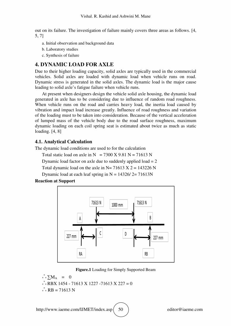
The dynamic load conditions are used to for the calculation
Total static load on axle in N = 7300 X 9.81 N = 71613 N
Dynamic load factor on axle due to suddenly applied load = 2
Total dynamic load on the axle in N= 71613 X 2 = 143226 N
Dynamic load at each leaf spring in N = 14326/ 2= 71613N
Reaction at Support
Figure.1 Loading for Simply Supported Beam
*** ∑MA = 0
*** RBX 1454 - 71613 X 1227 -71613 X 227 = 0
*** RB = 71613 N
71613 N 71613 N 1000 mm
227 mm 227 mm
RA
RB
A
B
C
D
Finite Element Analysis and Optimization of Tractor Trolley Axle
http://www.iaeme.com/IJMET/index.asp 51 [email protected]
And now finding the reaction at point B, we take the summation of the vertical
forces,
*** RA + RB – 71613- 71613 = 0
*** RA = 71613 N
Bending moments are zero at the end of simply supported beam
Bending moment at point A = 0 KN- mm
Bending moment at point B = 0 KN- mm
Now we find the bending moment at point C, D
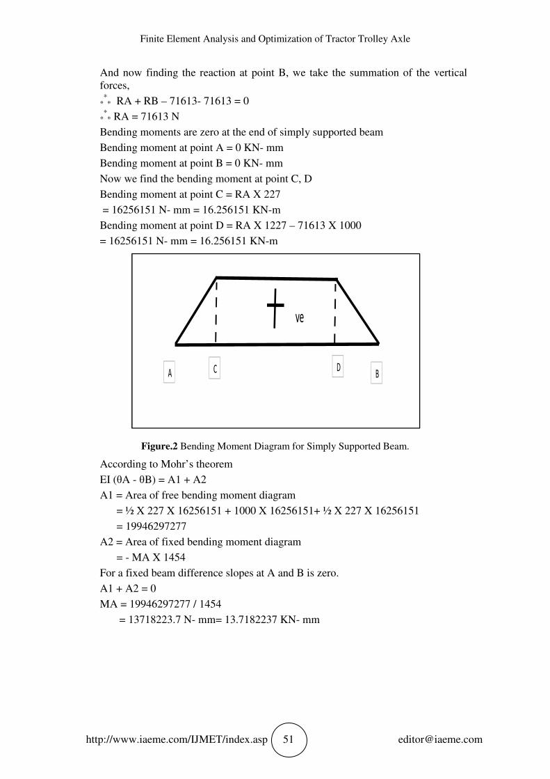
Bending moment at point C = RA X 227
= 16256151 N- mm = 16.256151 KN-m
Bending moment at point D = RA X 1227 – 71613 X 1000
= 16256151 N- mm = 16.256151 KN-m
Figure.2 Bending Moment Diagram for Simply Supported Beam.
According to Mohr’s theorem
EI (θA - θB) = A1 + A2
A1 = Area of free bending moment diagram
= ½ X 227 X 16256151 + 1000 X 16256151+ ½ X 227 X 16256151
= 19946297277
A2 = Area of fixed bending moment diagram
= - MA X 1454
For a fixed beam difference slopes at A and B is zero.
A1 + A2 = 0
MA = 19946297277 / 1454
= 13718223.7 N- mm= 13.7182237 KN- mm
ve
A
B
C
D
Vishal. R. Kashid and Ashwini M. Mane
http://www.iaeme.com/IJMET/index.asp 52 [email protected]
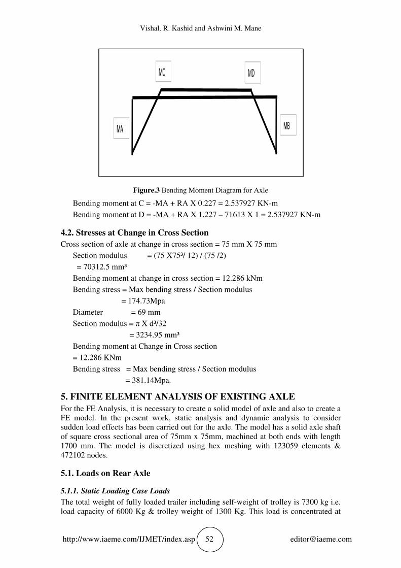
Figure.3 Bending Moment Diagram for Axle
Bending moment at C = -MA + RA X 0.227 = 2.537927 KN-m
Bending moment at D = -MA + RA X 1.227 – 71613 X 1 = 2.537927 KN-m
4.2. Stresses at Change in Cross Section
Cross section of axle at change in cross section = 75 mm X 75 mm
Section modulus = (75 X75³/ 12) / (75 /2)
= 70312.5 mm³
Bending moment at change in cross section = 12.286 kNm
Bending stress = Max bending stress / Section modulus
= 174.73Mpa
Diameter = 69 mm
Section modulus = π X d³/32
= 3234.95 mm³
Bending moment at Change in Cross section
= 12.286 KNm
Bending stress = Max bending stress / Section modulus
= 381.14Mpa.
5. FINITE ELEMENT ANALYSIS OF EXISTING AXLE
For the FE Analysis, it is necessary to create a solid model of axle and also to create a
FE model. In the present work, static analysis and dynamic analysis to consider
sudden load effects has been carried out for the axle. The model has a solid axle shaft
of square cross sectional area of 75mm x 75mm, machined at both ends with length
1700 mm. The model is discretized using hex meshing with 123059 elements &
472102 nodes.
5.1. Loads on Rear Axle
5.1.1. Static Loading Case Loads
The total weight of fully loaded trailer including self-weight of trolley is 7300 kg i.e.
load capacity of 6000 Kg & trolley weight of 1300 Kg. This load is concentrated at
MB
MD
MC
MA
Finite Element Analysis and Optimization of Tractor Trolley Axle
http://www.iaeme.com/IJMET/index.asp 53 [email protected]
two mounting points for leaf spring on the axle as shown in Figure 6.6 & axle is
shown in Figure 6.5
Y = 9810 mm/s²- Gravity for self- weight of axle
Y = - 35807 N - Gross load at leaf spring
= (Pay load + Trolley load) x 9810 / 2
= (6 + 1.3) x 9810 / 2
STEPS
• Model
• Geometry
Part 1
• Mesh
• Static Structural
Analysis settings
Loads
Supports
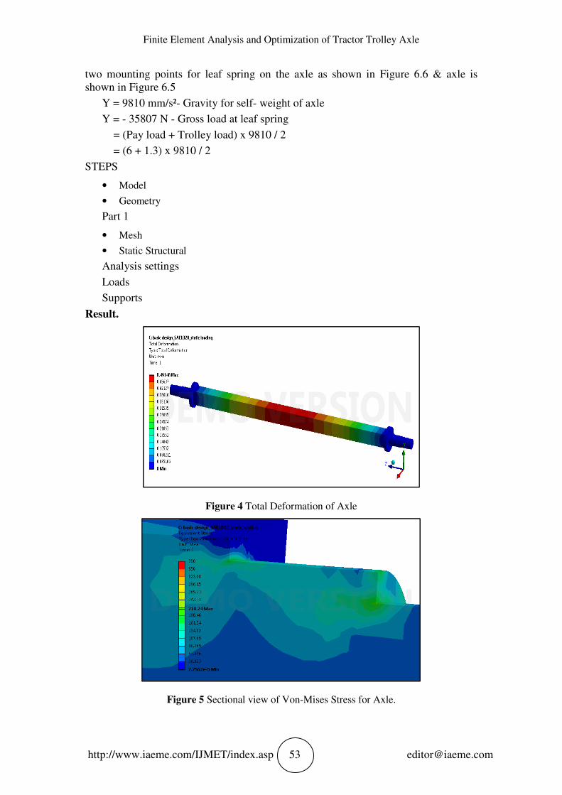
Result.
Figure 4 Total Deformation of Axle
Figure 5 Sectional view of Von-Mises Stress for Axle.
Vishal. R. Kashid and Ashwini M. Mane
http://www.iaeme.com/IJMET/index.asp 54 [email protected]
5.1.2. Dynamic Loading Case
5.1.2.1. Loads
The total weight of fully loaded trailer including self-weight of trolley is 7300 kg i.e.
load capacity of 6000 Kg & trolley weight of 1300 Kg. This load is concentrated at
two mounting points for leaf spring on the axle as shown in figure 6.13 Because of the
vertical acceleration of lumped mass of the vehicle body due to the road surface
roughness, maximum dynamic loading estimated about twice as much as static
loading & load acting at each point is 7300 x 9.81 =71613 N.
Y = 9810 mm/s2 - Gravity for self- weight of axle
Y = - 71613 N: Gross load at leaf spring
= (Pay load + Trolley load) x 9810 x Dynamic Factor / 2= (6 + 1.3) x 9810 x 2 / 2
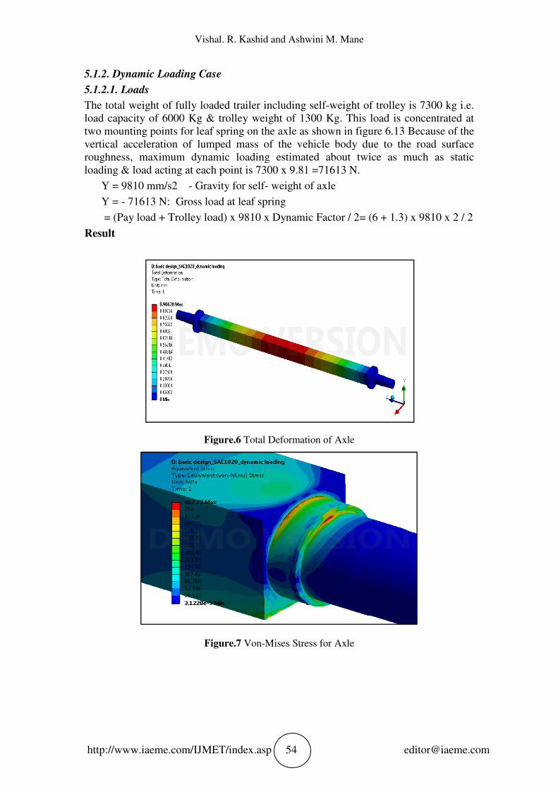
Result
Figure.6 Total Deformation of Axle
Figure.7 Von-Mises Stress for Axle
Finite Element Analysis and Optimization of Tractor Trolley Axle
http://www.iaeme.com/IJMET/index.asp 55 [email protected]
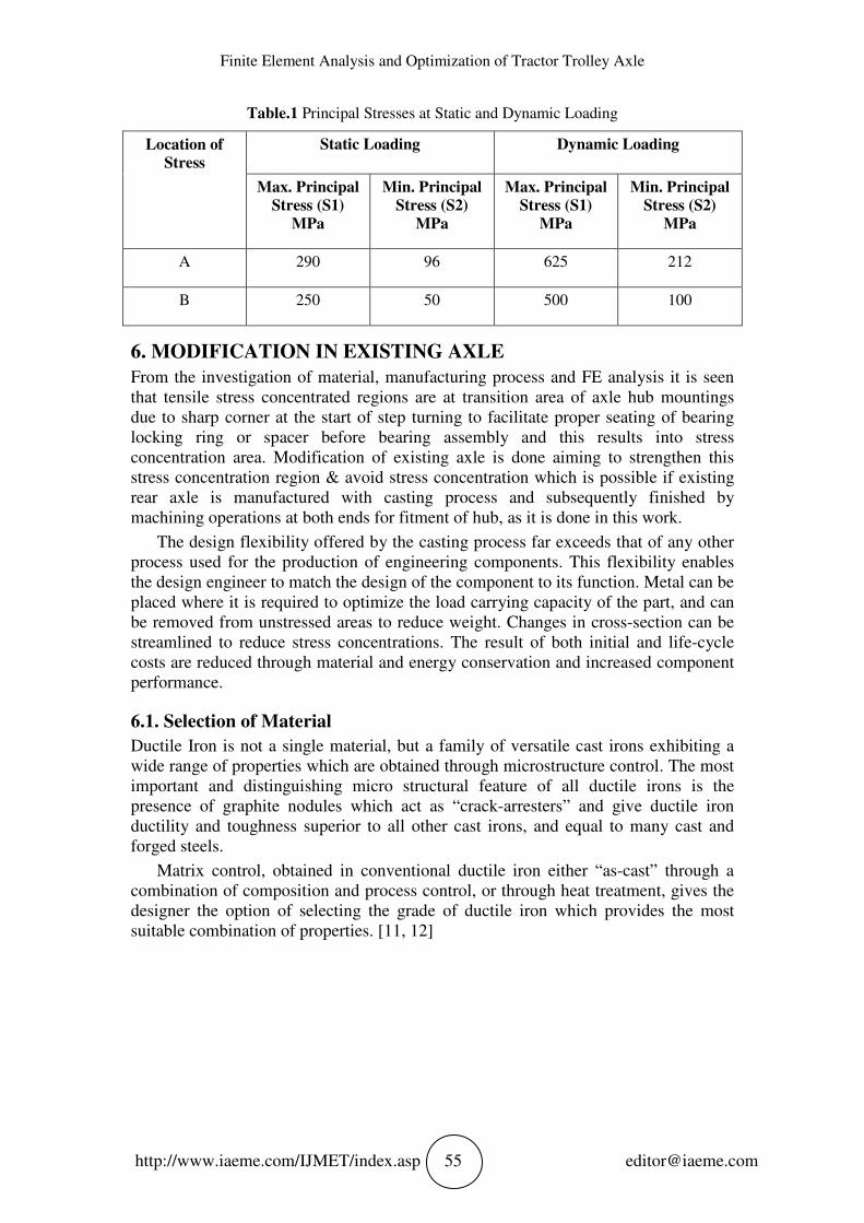
Table.1 Principal Stresses at Static and Dynamic Loading
Location of
Stress
Static Loading Dynamic Loading
Max. Principal
Stress (S1)
MPa
Min. Principal
Stress (S2)
MPa
Max. Principal
Stress (S1)
MPa
Min. Principal
Stress (S2)
MPa
A 290 96 625 212
B 250 50 500 100
6. MODIFICATION IN EXISTING AXLE
From the investigation of material, manufacturing process and FE analysis it is seen
that tensile stress concentrated regions are at transition area of axle hub mountings
due to sharp corner at the start of step turning to facilitate proper seating of bearing
locking ring or spacer before bearing assembly and this results into stress
concentration area. Modification of existing axle is done aiming to strengthen this
stress concentration region & avoid stress concentration which is possible if existing
rear axle is manufactured with casting process and subsequently finished by
machining operations at both ends for fitment of hub, as it is done in this work.
The design flexibility offered by the casting process far exceeds that of any other
process used for the production of engineering components. This flexibility enables
the design engineer to match the design of the component to its function. Metal can be
placed where it is required to optimize the load carrying capacity of the part, and can
be removed from unstressed areas to reduce weight. Changes in cross-section can be
streamlined to reduce stress concentrations. The result of both initial and life-cycle
costs are reduced through material and energy conservation and increased component
performance.
6.1. Selection of Material
Ductile Iron is not a single material, but a family of versatile cast irons exhibiting a
wide range of properties which are obtained through microstructure control. The most
important and distinguishing micro structural feature of all ductile irons is the
presence of graphite nodules which act as “crack-arresters” and give ductile iron
ductility and toughness superior to all other cast irons, and equal to many cast and
forged steels.
Matrix control, obtained in conventional ductile iron either “as-cast” through a
combination of composition and process control, or through heat treatment, gives the
designer the option of selecting the grade of ductile iron which provides the most
suitable combination of properties. [11, 12]
Vishal. R. Kashid and Ashwini M. Mane
http://www.iaeme.com/IJMET
Table.
Specifications
Tensile strength, min MPa
Yield strength, min, MPa
Elongation in 50 mm, min, %
Endurance Strength Mpa
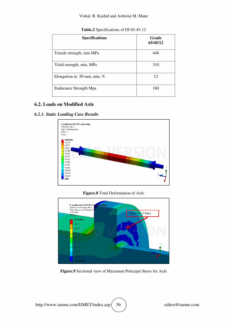
6.2. Loads on Modified Axle
6.2.1. Static Loading Case
Figure.9 Sectional view of Maximum
Vishal. R. Kashid and Ashwini M. Mane
IJMET/index.asp 56
Table.2 Specifications of DI 65-45-12
Specifications Grade
65/45/12
Tensile strength, min MPa 448
Yield strength, min, MPa 310
Elongation in 50 mm, min, % 12
Endurance Strength Mpa 180
Loads on Modified Axle
Static Loading Case Results
Figure.8 Total Deformation of Axle
Sectional view of Maximum Principal Stress for Axle
Principal Stress for Axle
Finite Element Analysis and Optimization of Tractor Trolley Axle
http://www.iaeme.com/IJMET/index.asp 57 [email protected]
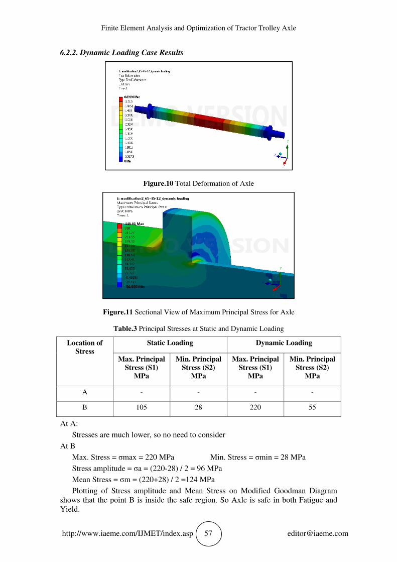
6.2.2. Dynamic Loading Case Results
Figure.10 Total Deformation of Axle
Figure.11 Sectional View of Maximum Principal Stress for Axle
Table.3 Principal Stresses at Static and Dynamic Loading
Location of
Stress
Static Loading Dynamic Loading
Max. Principal
Stress (S1)
MPa
Min. Principal
Stress (S2)
MPa
Max. Principal
Stress (S1)
MPa
Min. Principal
Stress (S2)
MPa
A - - - -
B 105 28 220 55
At A:
Stresses are much lower, so no need to consider
At B
Max. Stress = σmax = 220 MPa Min. Stress = σmin = 28 MPa
Stress amplitude = σa = (220-28) / 2 = 96 MPa
Mean Stress = σm = (220+28) / 2 =124 MPa
Plotting of Stress amplitude and Mean Stress on Modified Goodman Diagram
shows that the point B is inside the safe region. So Axle is safe in both Fatigue and
Yield.
Vishal. R. Kashid and Ashwini M. Mane
http://www.iaeme.com/IJMET/index.asp 58 [email protected]
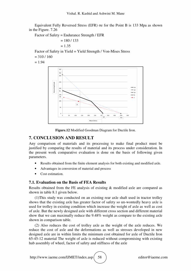
Equivalent Fully Reversed Stress (EFR) σe for the Point B is 133 Mpa as shown
in the Figure. 7.26
Factor of Safety = Endurance Strength / EFR
= 180 / 133
= 1.35
Factor of Safety in Yield = Yield Strength / Von-Mises Stress
= 310 / 160
= 1.94
Figure.12 Modified Goodman Diagram for Ductile Iron.
7. CONCLUSION AND RESULT
Any comparison of materials and its processing to make final product must be
justified by comparing the results of material and its process under consideration. In
the present work comparative evaluation is done on the basis of following given
parameters.
• Results obtained from the finite element analysis for both existing and modified axle.
• Advantages in conversion of material and process
• Cost estimation.
7.1. Evaluation on the Basis of FEA Results
Results obtained from the FE analysis of existing & modified axle are compared as
shown in table 8.1 given below.
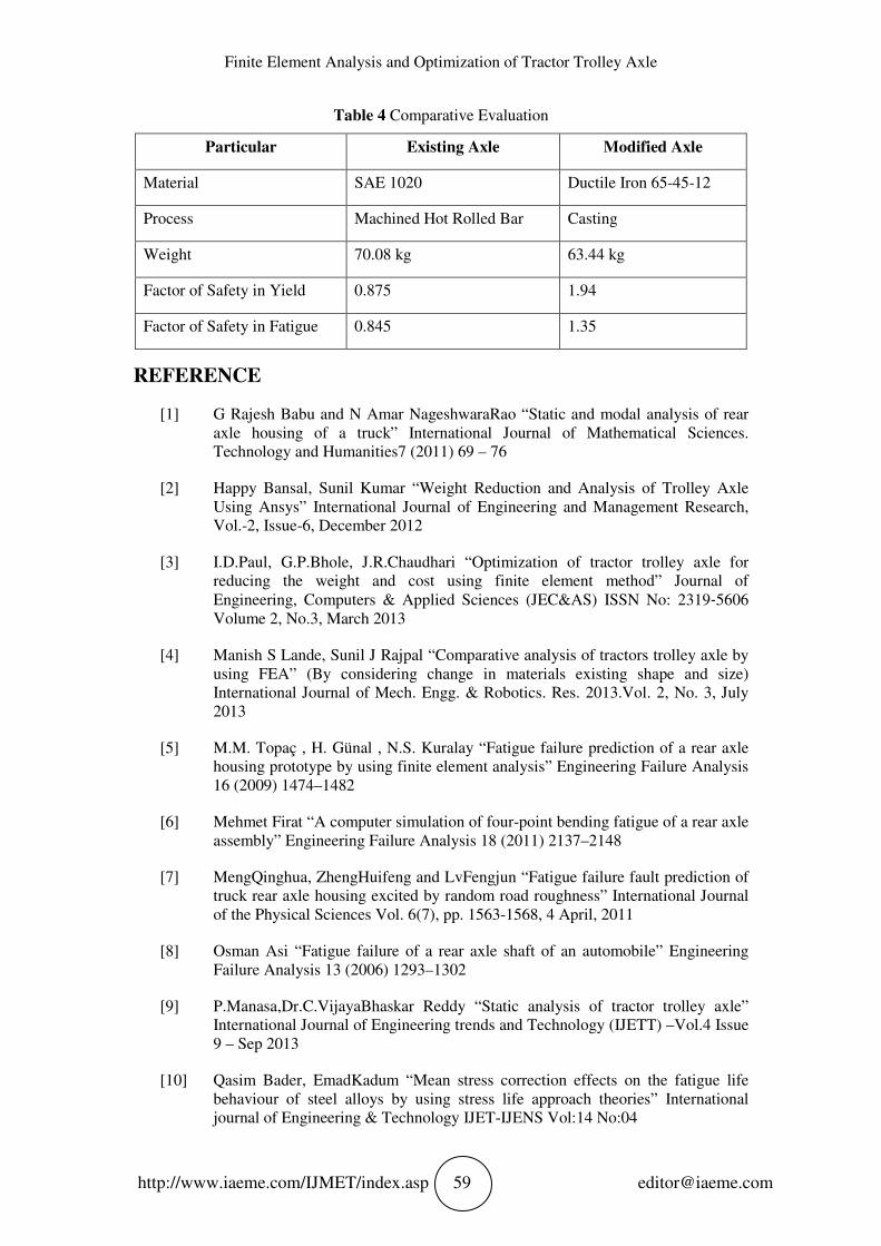
(1)This study was conducted on an existing rear axle shaft used in tractor trolley
shows that the existing axle has greater factor of safety so un-wontedly heavy axle is
used for trolley in existing condition which increase the weight of axle as well as cost
of axle. But the newly designed axle with different cross section and different material
show that we can maximally reduce the 9.48% weight as compare to the existing axle
shown in comparison table.
(2) Also reduces the cost of trolley axle as the weight of the axle reduces. We
reduce the cost of axle and the deformations as well as stresses developed in new
designed axle are in within limits the minimum cost obtained for axle of Ductile Iron
65-45-12 material The weight of axle is reduced without compromising with existing
hub assembly of wheel, factor of safety and stiffness of the axle
0
50
100
150
200
250
300
350
0 50 100 150 200 250 300 350 400 450 500
Sut
Syt
Syt
Se
2
Str
ess
Am
pli
tud
e
Mean Stress
B
Syt
Syt
Sut
Se
σe
Finite Element Analysis and Optimization of Tractor Trolley Axle
http://www.iaeme.com/IJMET/index.asp 59 [email protected]
Table 4 Comparative Evaluation
Particular Existing Axle Modified Axle
Material SAE 1020 Ductile Iron 65-45-12
Process Machined Hot Rolled Bar Casting
Weight 70.08 kg 63.44 kg
Factor of Safety in Yield 0.875 1.94
Factor of Safety in Fatigue 0.845 1.35
REFERENCE
[1] G Rajesh Babu and N Amar NageshwaraRao “Static and modal analysis of rear
axle housing of a truck” International Journal of Mathematical Sciences.
Technology and Humanities7 (2011) 69 – 76
[2] Happy Bansal, Sunil Kumar “Weight Reduction and Analysis of Trolley Axle
Using Ansys” International Journal of Engineering and Management Research,
Vol.-2, Issue-6, December 2012
[3] I.D.Paul, G.P.Bhole, J.R.Chaudhari “Optimization of tractor trolley axle for
reducing the weight and cost using finite element method” Journal of
Engineering, Computers & Applied Sciences (JEC&AS) ISSN No: 2319‐5606
Volume 2, No.3, March 2013
[4] Manish S Lande, Sunil J Rajpal “Comparative analysis of tractors trolley axle by
using FEA” (By considering change in materials existing shape and size)
International Journal of Mech. Engg. & Robotics. Res. 2013.Vol. 2, No. 3, July
2013
[5] M.M. Topaç , H. Günal , N.S. Kuralay “Fatigue failure prediction of a rear axle
housing prototype by using finite element analysis” Engineering Failure Analysis
16 (2009) 1474–1482
[6] Mehmet Firat “A computer simulation of four-point bending fatigue of a rear axle
assembly” Engineering Failure Analysis 18 (2011) 2137–2148
[7] MengQinghua, ZhengHuifeng and LvFengjun “Fatigue failure fault prediction of
truck rear axle housing excited by random road roughness” International Journal
of the Physical Sciences Vol. 6(7), pp. 1563-1568, 4 April, 2011
[8] Osman Asi “Fatigue failure of a rear axle shaft of an automobile” Engineering
Failure Analysis 13 (2006) 1293–1302
[9] P.Manasa,Dr.C.VijayaBhaskar Reddy “Static analysis of tractor trolley axle”
International Journal of Engineering trends and Technology (IJETT) –Vol.4 Issue
9 – Sep 2013
[10] Qasim Bader, EmadKadum “Mean stress correction effects on the fatigue life
behaviour of steel alloys by using stress life approach theories” International
journal of Engineering & Technology IJET-IJENS Vol:14 No:04
Vishal. R. Kashid and Ashwini M. Mane
http://www.iaeme.com/IJMET/index.asp 60 [email protected]
[11] R.A.Gujar,S.V.Bhaskar “ Shaft design under fatigue loading by using modified
Goodman method” International Journal of Engineering Research and
Application (IJERA) –Vol.3 Issue 4 – July- Aug 2013, pp.1061-1066
[12] SrivatsanKannan, Sivakumar M. Srinivasan “Influence of manufacturing
processes and their sequence of execution on fatigue life of axle house tubes in
automobiles” Engineering Failure Analysis 34 (2013) 79–92
[13] Abhijeet Rane, Gajendra V. Patil, Gajanan Thokal and Vinayak Khatwate,
Design and Optimization of Electrostatic Precipitator using Finite Element
Analysis Tool, "International Journal of Mechanical Engineering and Technology
(IJMET)", 5(1), 2014, pp.90–97.
[14] V. S. Khangar, Dr. S. B. Jaju “A Review of Various Methodologies Used for
shaft failure analysis” International Journal of Emerging Technology and
Advanced Engineering.
[15] “Annual Meeting Report June-2012”, by Ductile Iron Society
[16] “Westermann Tables”, by Jutz-Scharkus.
[17] “Mechanical Engineering Design”, by J.E. Shigley, McGraw Hill.
[18] Shubham Srivastava, Satish Kulkarni and Kiran Shet, A Comparative Study of
Two Methodologies for Non Linear Finite Element Analysis of Knife Edge Gate
Valve Sleeve, "International Journal of Mechanical Engineering and Technology
(IJMET)", 6(12), 2016, pp.81–90.
[19] “Introduction to Physical Metallurgy”, by Sideny H. Avner, McGraw Hill.