DSP 2 MARKS Q&A1
38
DSP Q&A GCE, NAMAKKAL Page 1 UNIT–I FAST FOURIER TRANSFORM 1. Define DFT and IDFT (or) what are the analysis and synthesis equations of DFT? DFT (Analysis Equation) N-1 X(k) = Σ x(n) e –j2πkn / N k = 0,1,2,3…….N-1 n=0 IDFT (Synthesis Equation) N-1 x(n) = 1/N Σ X(K) e j2πkn / N n = 0,1,2,3…….N-1 k=0 2. State the properties of DFT. 1. Periodicity 2. Linearity and symmetry 3. Multiplication of two DFTs 4. Circular convolution 5. Time reversal 6. Circular time shift and frequency shift 7. Complex conjugate 8. Circular correlation 3. Compute the DFT of x(n) = δ(n-n0) Given x(n) = δ(n-n0) = 1, when n=n0 = 0, otherwise N-1 X (k) = Σ x(n) e –j2πkn / N k = 0,1,2,3…….N-1 n=0 N-1 X (k) = Σ x(n) e –j2πkn0/ N k = 0,1,2,3…….N-1 n=0 = e –j2πkn0/ N 4. Find out the DFT of the signal X(n)= δ (n) δ(n) = ቄ 1 for n = 0 0 for n ≠ 0 X(n)={1,0,0,0} X(k) = ∑ x(n) ଵ ୬ୀ e ୨ଶπ୬୩ / k = 0,1,2,3 … … . N − 1 X(k) = x(n) ଷ ୬ୀ e ୨ଶπ୬୩ /ସ k = 0,1,2,3 X(k) = x(0) + x(1)e ୨୩π ଶ + x(2)e ୨୩π + x(3)e ୨ଷ୩π ସ k = 0,1,2,3. X(k)={1,1,1,1} 5. Define circular convolution. Let x1(n) and x2(n) are finite duration sequences both of length n with DFTs x1(k) and x2(k).If x3(k) = x1(k) x2(k), then the sequence x3(k) can be obtained by circular convolution, defined as N-1 x3(n) = Σ x1(n) x2(m-n) n=0
Transcript of DSP 2 MARKS Q&A1
DSP Q&A
GCE, NAMAKKAL Page 1
UNIT–I FAST FOURIER TRANSFORM
1. Define DFT and IDFT (or) what are the analysis and synthesis equations of DFT? DFT (Analysis Equation)
N-1 X(k) = Σ x(n) e –j2πkn / N k = 0,1,2,3…….N-1
n=0 IDFT (Synthesis Equation)
N-1 x(n) = 1/N Σ X(K) ej2πkn / N n = 0,1,2,3…….N-1
k=0 2. State the properties of DFT.
1. Periodicity 2. Linearity and symmetry 3. Multiplication of two DFTs 4. Circular convolution 5. Time reversal 6. Circular time shift and frequency shift 7. Complex conjugate 8. Circular correlation
3. Compute the DFT of x(n) = δ(n-n0) Given x(n) = δ(n-n0) = 1, when n=n0
= 0, otherwise N-1
X (k) = Σ x(n) e –j2πkn / N k = 0,1,2,3…….N-1 n=0
N-1 X (k) = Σ x(n) e –j2πkn0/ N k = 0,1,2,3…….N-1
n=0 = e –j2πkn0/ N
4. Find out the DFT of the signal X(n)= δ (n)
δ(n) = 1 for n = 00 for n ≠ 0 X(n)=1,0,0,0
X(k) = ∑ x(n) e π / k = 0,1,2,3 … … . N − 1
X(k) = x(n) e π / k = 0,1,2,3
X(k) = x(0) + x(1)e π+ x(2)e π + x(3)e
π k = 0,1,2,3.
X(k)=1,1,1,1
5. Define circular convolution. Let x1(n) and x2(n) are finite duration sequences both of length n with DFTs x1(k) and x2(k).If x3(k) = x1(k) x2(k), then the sequence x3(k) can be obtained by circular convolution, defined as
N-1 x3(n) = Σ x1(n) x2(m-n)
n=0
DSP Q&A
GCE, NAMAKKAL Page 2
6. IF N-point sequence x(n) has N- point DFT X(k) then what is the DFT of the following?
NjN enxivlnxiiinNxiinxi ln/2)()())(()()()()()(
Solution:
NNj
NkljN
lkXenxDFTivekXlnxDFTiii
kXnNxDFTiikNXnxDFTi
))(()()()())(()()()()(
)()()(
ln/2
/2
7. Calculate the DFT of the sequence x(n) = 1641
forN
n
Solution:
1
0
/2)()(N
n
NknjenxkX K=0, 1 , 2…..N-1
8/
216
15
0
8/
16/215
0
411
411
41
41
kj
kj
n
n
kj
knjn
n
e
e
e
e
8. State the time shifting property of DFT.
The time shifting properties of DFT states that If DFT[x(n)] = X(k), then DFT[x ((n-m)) N] = )(/2 kXe Nknj
DSP Q&A
GCE, NAMAKKAL Page 3
9. Find the DFT of the sequence x(n) = 1,1,0,0 Solution:
1
0
/2)()(N
n
NknjenxkX ; k = 0,1,2,…..N-1.
32 /4
0
3
0
3/2
03
0
33 /2
0
( ) 0,1, 2 , 3.
(0) ( ) 1 1 0 0 2
(1) ( ) 1 0 0 1
(2) ( ) 1 1 0 0 0
(3) ( ) 1 0 0 1
( ) 2,1 , 0,1
j kn
n
n
j n
n
j n
n
j n
n
x n e k
X x n
X x n e j j
X x n e
X x n e j j
X k j j
10. How to obtain same result from linear and circular convolution?
To obtain the same result from both convolutions the following steps are used: 1. Calculate the value of N. that means number of samples contained in linear Convolution. 2. By doing zero padding make the length of samples contained in linear convolution. 3. Perform the circular convolution; the result of circular and linear convolution will
be same. 11. What is the main advantage of FFT algorithm?
Fast Fourier Transform reduces the computation time required to compute Discrete Fourier Transform.
12. When the DFT X(k) of a sequence x(n) is imaginary? If the sequence x(n) is real and odd (or) imaginary and even, then X(k) is purely imaginary.
13. When the DFT X(k) of a sequence x(n) is real? If the sequence x(n) is real and even (or) imaginary and odd , then X(k) is purely real
14. State Circular frequency shifting property of DFT.
The circular frequency shifting property of DFT states that If DFT[x(n)]=X(k),
Then DFT[x(n) N
Nj lkXe ))((]ln/2
DSP Q&A
GCE, NAMAKKAL Page 4
15. What is FFT? FFT is a method for computing the DFT with reduced number of calculations using symmetry and periodicity properties of twiddle factor WNk. The computational efficiency is achieved by employing divide and conquers approach. This is based on the decomposing of an N point DFT into successively smaller DFTs to increase the speed of computation.
16. Why FFT is needed? The direct evaluation DFT requires N2 complex multiplications and N2 –N complex
additions. Thus for large values of N direct evaluation of the DFT is difficult. By using FFT algorithm the number of complex computations can be reduced. So we use FFT. FFT is needed to compute DFT with reduced number of calculations. DFT is required for spectrum analysis and filtering operations on the signals using digital computers.
17. How many multiplications and additions are required to compute N point DFT
using Radix-2 FFT? The total number of multiplications and additions required to compute N point DFT
using radix-2 FFT are N log2 N complex additions and N/2 log2 N complex multiplications respectively.
18. Calculate the number of multiplications needed in the calculation of DFT and FFT
with 64- Point sequence. The number of complex multiplications required using direct computation is N2 = 642
= 4096 . The number of complex multiplications required using FFT is (N/2) log2 N = (64/2) log264 = 192
19. Calculate the number of multiplications needed in the calculation of DFT using FFT with 32- Point sequence.
The number of complex multiplications required using FFT is (N/2) log2N = (32/2) log232 = 80
20. What is meant by radix-2 FFT? The FFT algorithm is most efficient in calculating N point DFT. If the number of
output points N can be expressed as a power of 2 that is N=2M, where M is an integer, then this algorithm is known as radix-2 algorithm.
21. What is DIT radix-2 algorithm?
Decimation-In-Time algorithm is used to calculate the DFT of a N point sequence. The idea is to break the N point sequence into two sequences, the DFTs of which can be combined to give the DFT of the original N point sequence. This algorithm is called DIT because the sequence x(n) is often spitted into smaller sub- sequences. In which the Time domain N-point sequences x(n) are converted into Frequency domain Npoint sequences X(k).
22. What is DIF radix-2 algorithm?
The radix 2 DIF FFT is an efficient algorithm for computing DFT in this the output sequence x(k) is divided in two smaller and smaller. The idea is to break N point sequence in to two sequences. In which the Frequency domain -point sequences X(k) are converted into the Time domain N-point sequences x(n).
DSP Q&A
GCE, NAMAKKAL Page 5
23. What are the applications of FFT algorithm? The applications of FFT algorithm includes 1. Linear filtering 2. Correlation 3. Spectrum analysis
24. Define Twiddle factor (or) Phase factor. The complex number WN is called as Twiddle factor (or) Phase factor. it also represent an Nth root of unity. It is expressed by WNkn = e –j2πkn / N
25. What are the properties of Twiddle factor (WNK )? 1. Periodicity Property
WNK+N = WNK 2. Symmetric Property WNK+N/2 = -WNK
26. What is zero padding? What are its uses? The process of lengthening the sequence by adding zero – valued samples is called appending with zeros or zero – padding. USES:
(i) We can get “better display” of the frequency spectrum. (ii) With zero padding, the DFT can be used in linear filtering.
27. How the circular convolution is obtained by using Graphical method?
Given two sequences )(1 nx and )(2 nx , the circular convolution of these two sequences )()()( 213 nNxnxnx can be obtained by using the following steps.
1. Graph N samples of )(1 nx , as equally spaced points around an outer circle in counter clockwise direction.
2. Start at the same point as )(1 nx graph N samples of )(2 nx as equally spaced points around an inner circle in clock wise direction.
3. Multiply corresponding samples on the two circles and sum the products to produce output.
4. Rotate the inner circle one sample at a time in clock wise direction and go to step3 to obtain the next value of output.
5. Repeat step4 until the inner circle first sample lines up with the first sample of the exterior circle once again.
28. Distinguish between linear and circular convolution of two sequences.
Sl.NO Linear Convolution Circular convolution 1. If x(n) is a sequence of L number of
samples and h(n) with M number of samples , after convolution y(n) will contain N=L+M-1
If x(n) is a sequence of L number of samples and h(n) with M number of samples , after convolution y(n) will contain N=Max(L,M) samples.
2. Linear convolution can be used to find the response of a linear filter.
Circular convolution cannot be used to find the response of a filter.
3. Zero padding is not necessary to find the response of a linear filter.
Zero padding is necessary to find the response of a filter.
DSP Q&A
GCE, NAMAKKAL Page 6
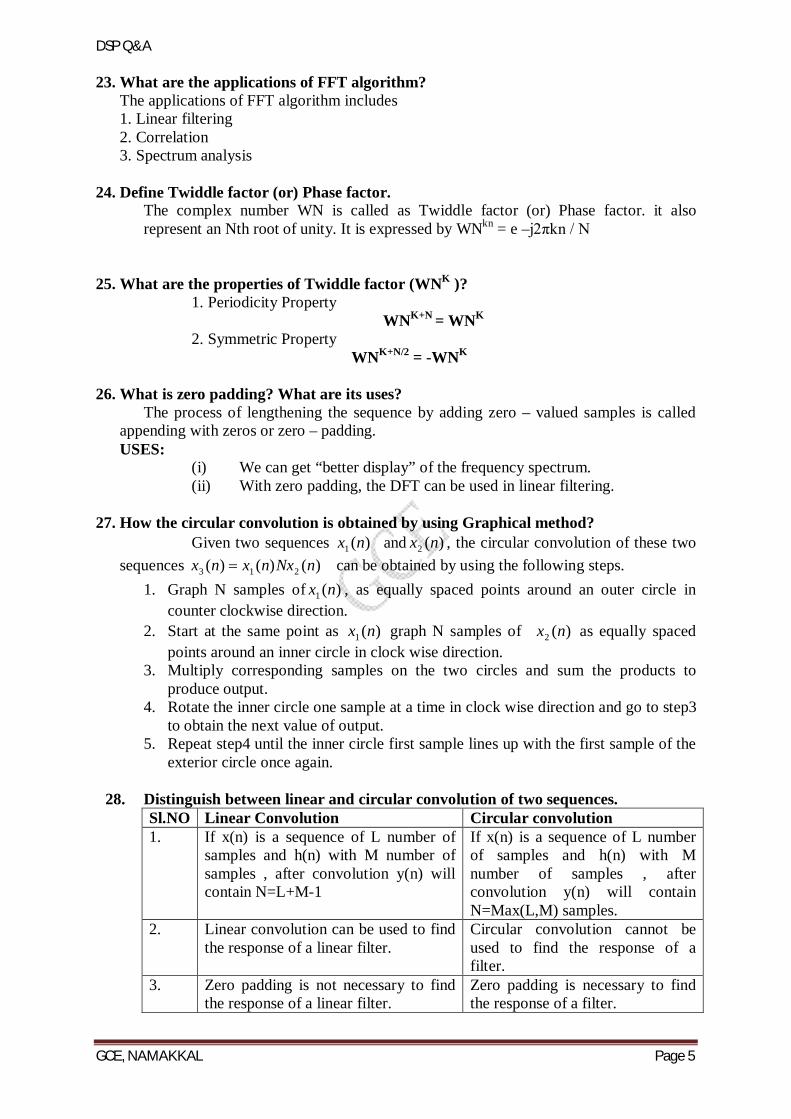
29. What is meant by bit reversal and in place commutation as applied to FFT? "Bit reversal" is just what it sounds like: reversing the bits in a binary word
from left to write. Therefore the MSB's become LSB's and the LSB's become MSB's.The data ordering required by radix-2 FFT's turns out to be in "bit reversed" order, so bit-reversed indexes are used to combine FFT stages.
Input sample index
Binary Representation
Bit reversed binary
Bit reversal sample index
0 000 000 0 1 001 100 4 2 010 010 2 3 011 110 6 4 100 001 1 5 101 101 5 6 110 011 3 7 111 111 7
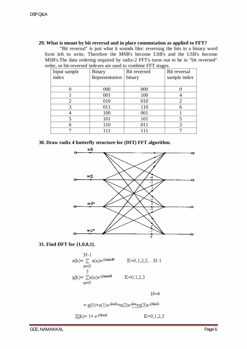
30. Draw radix 4 butterfly structure for (DIT) FFT algorithm.
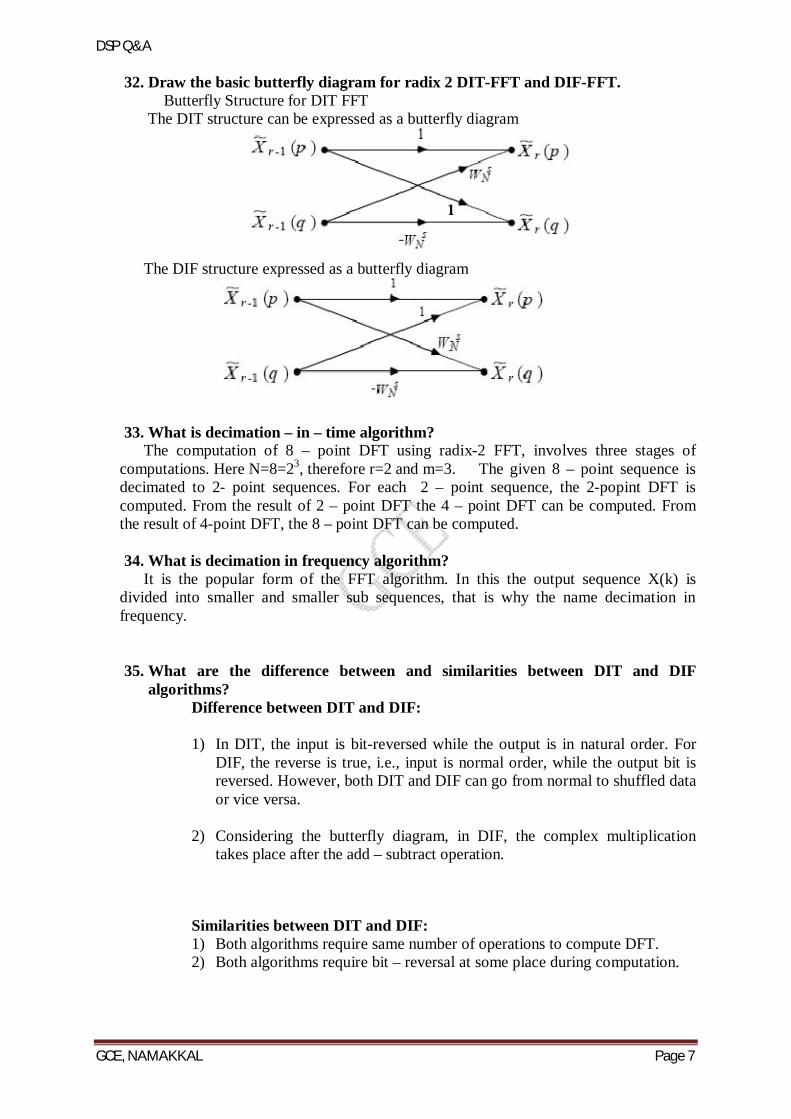
31. Find DFT for 1,0,0,1.
DSP Q&A
GCE, NAMAKKAL Page 7
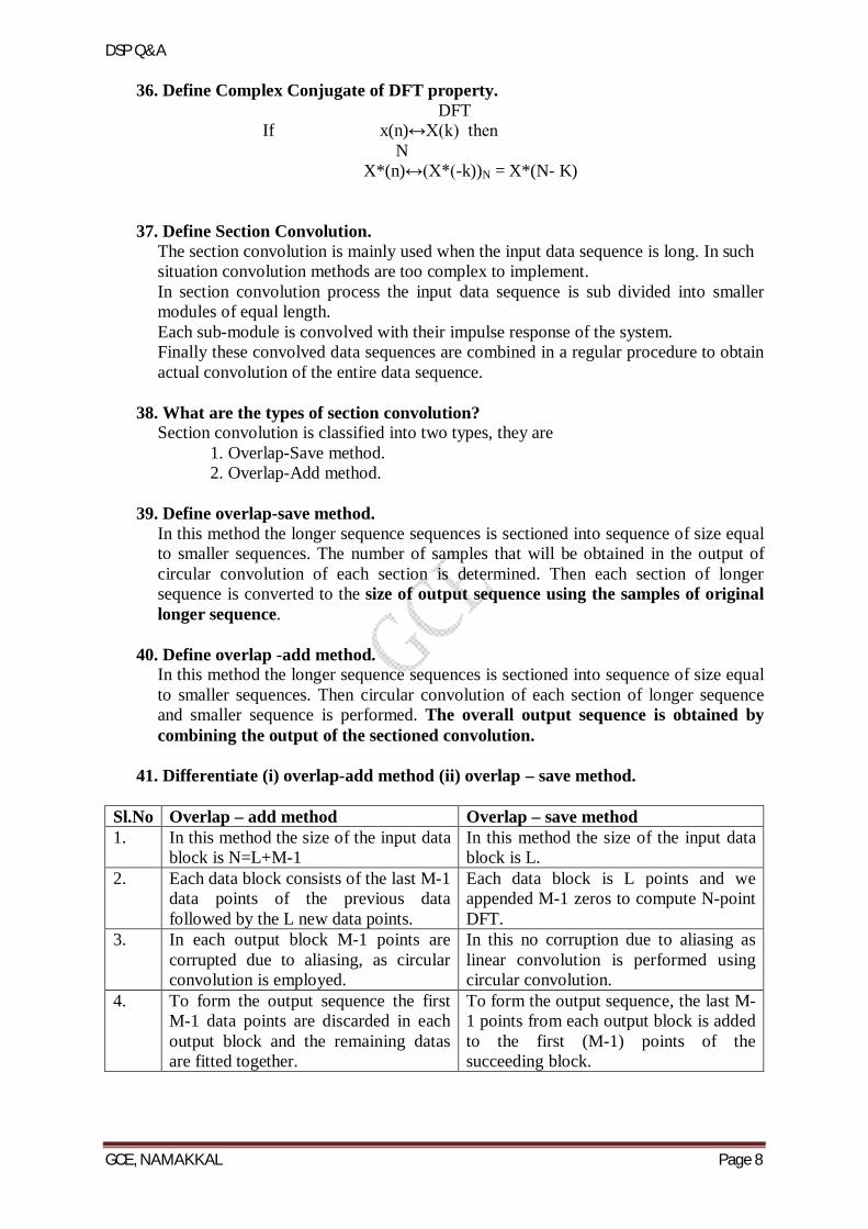
32. Draw the basic butterfly diagram for radix 2 DIT-FFT and DIF-FFT. Butterfly Structure for DIT FFT The DIT structure can be expressed as a butterfly diagram
The DIF structure expressed as a butterfly diagram
33. What is decimation – in – time algorithm? The computation of 8 – point DFT using radix-2 FFT, involves three stages of computations. Here N=8=23, therefore r=2 and m=3. The given 8 – point sequence is decimated to 2- point sequences. For each 2 – point sequence, the 2-popint DFT is computed. From the result of 2 – point DFT the 4 – point DFT can be computed. From the result of 4-point DFT, the 8 – point DFT can be computed. 34. What is decimation in frequency algorithm?
It is the popular form of the FFT algorithm. In this the output sequence X(k) is divided into smaller and smaller sub sequences, that is why the name decimation in frequency. 35. What are the difference between and similarities between DIT and DIF
algorithms? Difference between DIT and DIF:
1) In DIT, the input is bit-reversed while the output is in natural order. For
DIF, the reverse is true, i.e., input is normal order, while the output bit is reversed. However, both DIT and DIF can go from normal to shuffled data or vice versa.
2) Considering the butterfly diagram, in DIF, the complex multiplication
takes place after the add – subtract operation.
Similarities between DIT and DIF: 1) Both algorithms require same number of operations to compute DFT. 2) Both algorithms require bit – reversal at some place during computation.
DSP Q&A
GCE, NAMAKKAL Page 8
36. Define Complex Conjugate of DFT property. DFT
If x(n)↔X(k) then N
X*(n)↔(X*(-k))N = X*(N- K)
37. Define Section Convolution. The section convolution is mainly used when the input data sequence is long. In such situation convolution methods are too complex to implement. In section convolution process the input data sequence is sub divided into smaller modules of equal length. Each sub-module is convolved with their impulse response of the system. Finally these convolved data sequences are combined in a regular procedure to obtain actual convolution of the entire data sequence.
38. What are the types of section convolution? Section convolution is classified into two types, they are
1. Overlap-Save method. 2. Overlap-Add method.
39. Define overlap-save method. In this method the longer sequence sequences is sectioned into sequence of size equal to smaller sequences. The number of samples that will be obtained in the output of circular convolution of each section is determined. Then each section of longer sequence is converted to the size of output sequence using the samples of original longer sequence.
40. Define overlap -add method. In this method the longer sequence sequences is sectioned into sequence of size equal to smaller sequences. Then circular convolution of each section of longer sequence and smaller sequence is performed. The overall output sequence is obtained by combining the output of the sectioned convolution.
41. Differentiate (i) overlap-add method (ii) overlap – save method.
Sl.No Overlap – add method Overlap – save method 1. In this method the size of the input data
block is N=L+M-1 In this method the size of the input data block is L.
2. Each data block consists of the last M-1 data points of the previous data followed by the L new data points.
Each data block is L points and we appended M-1 zeros to compute N-point DFT.
3. In each output block M-1 points are corrupted due to aliasing, as circular convolution is employed.
In this no corruption due to aliasing as linear convolution is performed using circular convolution.
4. To form the output sequence the first M-1 data points are discarded in each output block and the remaining datas are fitted together.
To form the output sequence, the last M-1 points from each output block is added to the first (M-1) points of the succeeding block.
DSP Q&A
GCE, NAMAKKAL Page 9
42. Distinguish between DFT and DTFT.
Sl.No DFT DTFT 1. Obtained by performing sampling
operation in both the time and frequency domains.
Sampling is performed only in time domain.
2. Discrete frequency spectrum Continuous function of
43. Determine the DIFT of a sequence x(n) = an u(n)
X(K) = x(n) ej2πkn/N
The given sequence x(n) = an u(n) DTFTx(n) = x(n) ej2πkn/N
= (a ej2πk/N)n Where an = 1-an/(1-a) X(K) = (1 – aNej2πk)/ (1-aej2πk/N)
44. What do you mean by in place computation in FFT. FFT algorithms, for computing the DFT when the size N is a power of 2 and when it is a power of 4.
45. Is the DFT is a finite length sequence periodic. Then state the reason DFT is a finite length sequence periodic.
N-1 X(ej )= Σ x(n) e-jn
n =0 X(ej ) is continuous & periodic in , with period 2π.
46. What is meant by Convolution? Convolution is a mathematical operation on two sequences x(n)and h(n), producing a third function y(n), that is typically viewed as a modified version of one of the original sequences. Convolution is similar to cross-correlation.
47. What are the types of convolution? Convolution is classified into two types, there are 1. Linear Convolution 2. Circular Convolution 3. Sectioned Convolution
48. What is Linear Convolution? The response of a LTI system for any arbitrary input is given by convolution of input x(n) and the impulse response h(n) of the system.
α y(n)= Σ x(k) h(n-k)
k=-α 49. Find the Fourier transform of a sequence x(n) = 1 for 22 n
= 0 otherwise.
Solution:
2
2
)()(n
nj
n
nj eenxX
22 1 jjjj eeee 2cos2cos21
DSP Q&A
GCE, NAMAKKAL Page 10
50. What are the different methods performing circular convolution? 1. Graphical method 2. Stockhman’s method 3. Tabular array method 4. Matrix method.
UNIT II FINITE IMPULSE RESPONSE DIGITAL FILTERS 1. Define filter
Filter is a frequency selective device, which amplifies particular range of frequencies and attenuate particular range of frequencies.
2. What are the types of digital filter according to their impulse response? IIR(Infinite impulse response )filter FIR(Finite Impulse Response)filter. 3. How phase distortion and delay distortion are introduced?
The phase distortion is introduced when the phase characteristics of a filter is nonlinear within the desired frequency band. The delay distortion is introduced when the delay is not constant within the desired
frequency band.
4. What is mean by FIR filter? The filter designed by selecting finite number of samples of impulse response (h(n) obtained from inverse Fourier transform of desired frequency response H(w)) are called FIR filters
5. Write the steps involved in FIR filter design Choose the desired frequency response Hd(w) Take the inverse Fourier transform and obtain Hd(n) Convert the infinite duration sequence Hd(n) to h(n) Take Z transform of h(n) to get H(Z) 6. What are advantages of FIR filter? Linear phase FIR filter can be easily designed.
Efficient realization of FIR filter exists as both recursive and non-recursive structures. FIR filter realized non-recursively stable. The round off noise can be made small in non recursive realization of FIR filter.
7. What are the disadvantages of FIR filter? The duration of impulse response should be large to realize sharp cut-off filters.
The non integral delay can lead to problems in some signal processing applications. 8. What is the necessary and sufficient condition for the linear phase characteristic of a
FIR filter? The phase function should be a linear function of w, which in turn requires constant group delay and phase delay. / O9/
9. List the well known design technique for linear phase FIR filter design? Fourier series method and window method Frequency sampling method. Optimal filter design method.
DSP Q&A
GCE, NAMAKKAL Page 11
10. What is gibb’s Phenomenon. The oscillatory behavior of the approximation XN(W) to the function X(w) at a point of discontinuity of X(w) is called Gibb’s Phenomenon
11. Write procedure for designing FIR filter using windows. 1. Begin with the desired frequency response specification Hd(w)
2. Determine the corresponding unit sample response hd(n) 3. Indeed hd(n) is related to Hd(w) by the Fourier Transform relation.
12. What are Gibbs oscillations? Oscillatory behavior observed when a square wave is reconstructed from finite number of harmonics.
The unit cell of the square wave is given by
Its Fourier series representation is
13. Explain briefly the need for scaling in the digital filter realization
To prevent overflow, the signal level at certain points in the digital filters must be scaled so that no overflow occur in the adder
14. Define Phase Dealy When the input signal X(n) is applied which has non zero response
the output signal y(n) experience a delay with respect to the input signal .Let the input signal be
X(n)=A , + Where A= Maximum Amplitude of the signal Wo=Frequency in radians f=phase angle Due to the delay in the system response ,the output signal lagging in phase but the frequency remain the same Y(n)= A , In This equation that the output is the time delayed signal and is more commonly
known as phase delayed at w=wo Is called phase delay 15. State the advantages and disadvantages of FIR filter over IIR filter. Advantages of FIR filter over IIR filter
It is a stable filter It exhibit linear phase, hence can be easily designed. It can be realized with recursive and non-recursive structures It is free of limit cycle oscillations when implemented on a finite word length
digital system Disadvantages of FIR filter over IIR filter
Obtaining narrow transition band is more complex. Memory requirement is very high Execution time in processor implementation is very high.
DSP Q&A
GCE, NAMAKKAL Page 12
16. List out the different forms of structural realization available for realizing a FIR system
The different types of structures for realization of FIR system are 1.Direct form-I 2. Direct form-II
17. What are the desirable and undesirable features of FIR Filters? The width of the main lobe should be small and it should contain as much of total energy as possible. The side lobes should decrease in energy rapidly as w tends to π. 18. Define Hanning and Blackman window functions
The window function of a causal hanning window is given by WHann(n) = 0.5 – 0.5cos2πn/ (M-1), 0≤n≤M-1
0, Otherwise The window function of non-causal Hanning window I s expressed by WHann(n) = 0.5 + 0.5cos2πn/ (M-1), 0≤|n|≤(M-1)/2
0, Otherwise The width of the main lobe is approximately 8π/M and thee peak of the first side lobe is at -32dB. The window function of a causal Blackman window is expressed by
WB(n) = 0.42 – 0.5 cos2πn/ (M-1) +0.08 cos4πn/(M-1), 0≤n≤M-1 = 0, otherwise The window function of a non causal Blackman window is expressed by
WB(n) = 0.42 + 0.5 cos2πn/ (M-1) +0.08 cos4πn/(M-1), 0≤|n|≤(M-1)/2 = 0, otherwise The width of the main lobe is approximately 12π/M and the peak of the first side lobe is at -58dB. 19. What is the condition for linear phase of a digital filter? h(n) = h(M-1-n) Linear phase FIR filter with a nonzero response at ω=0 h(n) = -h(M-1-n)Low pass Linear phase FIR filter with a nonzero response at ω=0 20. Define backward and forward predictions in FIR lattice filter. The reflection coefficient in the lattice predictor is the negative of the cross correlation coefficients between forward and backward prediction errors in the lattice. 21. List the important characteristics of physically realizable filters
Symmetric and anti- symmetric Linear phase frequency response Impulse invariance
22. Write the magnitude function of Butterworth filter. What is the effect of varying order of N on magnitude and phase response?
|H(jΏ)|2 = 1 / [ 1 + (Ώ/ΏC)2N] where N= 1,2,3,….
23. List the characteristics of FIR filters designed using window functions. The Fourier transform of the window function W(ejw) should have a small width of main lobe containing as much of the total energy as possible. The fourier transform of the window function W(ejw) should have side lobes that decrease in energy rapidly as w to π. Some of the most frequently used window functions are described in the following sections
24. Give the Kaiser Window function. The Kaiser Window function is given by WK(n) = I0(β) / I0(α) , for |n| ≤ (M-1)/2 Where α is an independent variable determined by Kaiser. Β = α[ 1 – (2n/M-1)2]
DSP Q&A
GCE, NAMAKKAL Page 13
25. What is meant by FIR filter? And why is it stable?
FIR filter Finite Impulse Response. The desired frequency response of a FIR filter can be represented as ∞ Hd(ejω)= Σ hd(n)e-jωn n= -∞
If h(n) is absolutely summable(i.e., Bounded Input Bounded Output Stable). So, it is in stable.
26. Mention two transformations to digitize an analog filter. (i) Impulse-Invariant transformation techniques (ii) Bilinear transformation techniques
27. Give the equation specifying Barlett and hamming window.
The transfer function of Barlett window wB(n) = 1-(2|n|)/(N-1), ((N-1)/2)≥n≥-((N-1)/2) The transfer function of Hamming window whm(n) = 0.54+0.46cos((2πn)/(N-1), ((N-1)/2)≥n≥-((N-1)/2) α = 0.54
28. What is the condition for the impulse response of FIR filter to satisfy for constant group and phase delay and for only constant group delay? For linear phase FIR filter to have both constant group delay and constant phase delay. )( For satisfying above condition )1()( nNhnh
that is the impulse response must be symmetrical about 2
1
Nn
If one constant group delay is desired then )( For satisfying the above condition )1()( nNhnh
that is the impulse response must be antisymmetrical about 2
1
Nn
29. What are the properties of FIR filter? The properties of FIR filters are
1. FIR filter is always stable because all its poles are at the origin. 2. A realizable filter can always be obtained. 3. FIR filter has a linear phase response.
30. How the constant group delay and phase delay is achieved in linear phase FIR
filters. Frequency response of FIR filters with constant group and phase delay )()()( jeHH The following conditions have to be satisfied to achieve constant group and phase delay.
Phase delay, 2
1
N (i.e., phase delay is constant)
Group delay, 2 (i.e., group delay is constant)
Impulse response, h(n) = - h( N -1 – n ) (i.e., impulse response is anti symmetric)
DSP Q&A
GCE, NAMAKKAL Page 14
31. What are the possible types of impulse response for linear phase FIR filters? There are four types of impulse response for linear phase FIR filters
1. Symmetric impulse response when N is odd. 2. Symmetric impulse response when N is even. 3. Antisymmetric impulse response when N is odd. 4. Antisymmetric impulse response when N is even.
32. Write the two concepts that lead to the Fourier series or window method of designing FIR filters.
The following two concepts lead to the design of FIR filters by Fourier series method. The frequency response of a digital filter is periodic with period equal to sampling frequency Any periodic function can be expressed as a linear combination of complex exponentials
33. Write the procedure for designing FIR filter by Fourier series method. The procedure for designing FIR filter by Fourier series method is
i) Choose the desired (ideal) frequency response )(dH of the filter i) Evaluate the Fourier series co-efficient of )(dH which gives the desired
impulse response )(nhd
deHnh njdd )(
21)(
ii) Truncate the infinite sequence )(nhd to a finite duration sequence)(nh
iii) Take Z – transform of )(nh to get a noncausal filter transfer function )(zH of the FIR filter
iv) Multiply )(zH by
2
1N
z to convert noncausal transfer function to a realizable causal FIR filter transfer function
)(zH
21
1
21
)()0(
N
n
nnN
zznhhz
34. What are the disadvantages of Fourier series method? In designing FIR filter using Fourier series method the infinite duration impulse
response is truncated at n=
2
1N . Direct truncation of the series will lead to fixed
percentage overshoots and undershoots before and after an approximated discontinuity in the frequency response
35. Write the procedure for designing FIR filter using windows. The procedure for designing FIR filter using windows are
i) Choose the desired (ideal) frequency response )(dH of the filter ii) Evaluate the Fourier series co-efficient of )(dH which gives the desired
impulse response )(nhd
deHnh njdd )(
21)(
iii) Choose a window sequence w(n) and multiply the infinite sequence )(nhd by w(n)to convert the infinite duration impulse response to finite
duration impulse response )(nh )()()( nwnhnh d
DSP Q&A
GCE, NAMAKKAL Page 15
iv) Find the transfer function of the realizable FIR filter
)(zH
21
1
21
)()0(
N
n
nnN
zznhhz
36. What are the desirable characteristics of the window?
The desirable characteristics of the window are 1. The central lobe of the frequency response of the window should contain most of
the energy and should be narrow 2. The highest side lobe level of the frequency response should be small 3. The side lobe of the frequency response should decrease in energy rapidly as
tends to 37. What is window and why it is necessary?
One possible way of finding an FIR filter that approximates )( jeH would be
to truncate the infinite Fourier series at n=
2
1N . The abrupt truncation of the
series will lead to oscillation both in passband and in stopband. These oscillations can be reduced through the use of less abrupt truncation of the Fourier series. This can be achieved by multiplying the infinite impulse response with a finite weighing )(nw , called a window.
38. List characteristics of FIR filter designed using windows. The characteristics of FIR filter designed using windows are
i) The width of the transition band depends on the type of window ii) The width of the transition band can be made narrow by increasing the value of N where N is the length of the window sequence
iii) The attenuation in the stop band is fixed for a given window, except in case of Kaiser window where it is variable
39. Write the procedure for FIR filter design by frequency sampling method. The procedures for FIR filter design by frequency sampling method are
1. Choose the desired frequency response )(dH 2. Take N – samples of )(dH to generate the sequence )(~ kH 3. Take inverse DFT of ).(~ kH to get the impulse response h(n) 4. The transfer function H(z) of the filter is obtained by taking Z – transform of
impulse response
40. What is meant by Optimum equiripple design criterion? Why it is followed? In FIR filter design by Chebyshev approximation technique, the weighted
approximation error between the desired frequency and the actual frequency response is spread evenly across the passband and stopband.The resulting filter will have ripples in both the passband and stopband. This concept of design is called optimum equiripple design criterion. The optimum equiripple criterion is used to design FIR filter in order to satisfy the specifications of passband and stopband.
41. Write the expression for frequency response of rectangular window. The frequency response of rectangular window is given by
2sin
2sin
)(
N
RW
DSP Q&A
GCE, NAMAKKAL Page 16
42. Write the characteristic features of rectangular window.
The characteristic features of rectangular window are
The main lobe width is equal to N4
The maximum sidelobe magnitude is -13dB The sidelobe magnitude does not decreases significantly with increasing
43. List the features of FIR filter designed using rectangular window.
The features of FIR filter designed using rectangular window are i) The width of the transition region is related to the width of the mainlobe of window spectrum ii) Gibb’s oscillations are noticed in the passband and stop band iii) The attenuation in the stopband is constant and cannot be varied
44. Write the equation specifying Hanning windows. The equation for Hanning window is given by
1
2cos5.05.0)(
N
nnw nH
for 2
)1(2
)1(
NnN
= 0 Otherwise. 45. Write the equation specifying Hamming windows.
The equation for Hamming window is given by
1
2cos46.054.0)(
N
nnwH
for 2
)1(2
)1(
NnN
= 0 Otherwise. 46. Write the equation specifying Blackman windows.
The equation for Blackman window is given by
14cos08.0
12cos5.042.0)(
Nn
NnnwB
for
2)1(
2)1(
NnN
= 0 Otherwise. 47. Write the equation specifying Kaiser windows.
The equation for Kaiser window is given by
)(
121
)(0
0
IN
n
Inwk for 2
)1(
Nn
= 0 Otherwise. Where
is an independent parameter. 0I (x) is the zeroth order Bessel function of the first kind
2
10 2!
11)(I
k
kxk
x
DSP Q&A
GCE, NAMAKKAL Page 17
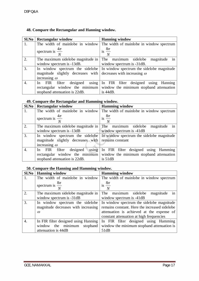
48. Compare the Rectangular and Hanning window.
Sl.No Rectangular window Hanning window 1. The width of mainlobe in window
spectrum is N4
The width of mainlobe in window spectrum
is N8
2. The maximum sidelobe magnitude in window spectrum is -13dB.
The maximum sidelobe magnitude in window spectrum is -31dB.
3. In window spectrum the sidelobe magnitude slightly decreases with increasing
In window spectrum the sidelobe magnitude decreases with increasing
4. In FIR filter designed using rectangular window the minimum stopband attenuation is 22dB.
In FIR filter designed using Hanning window the minimum stopband attenuation is 44dB.
49. Compare the Rectangular and Hamming window.
Sl.No Rectangular window Hamming window 1. The width of mainlobe in window
spectrum is N4
The width of mainlobe in window spectrum
is N8
2. The maximum sidelobe magnitude in window spectrum is -13dB
The maximum sidelobe magnitude in window spectrum is -41dB
3. In window spectrum the sidelobe magnitude slightly decreases with increasing
In window spectrum the sidelobe magnitude remains constant
4. In FIR filter designed using rectangular window the minimum stopband attenuation is 22dB.
In FIR filter designed using Hamming window the minimum stopband attenuation is 51dB
50. Compare the Hanning and Hamming window.
Sl.No Hanning window Hamming window 1. The width of mainlobe in window
spectrum is N8
The width of mainlobe in window spectrum
is N8
2. The maximum sidelobe magnitude in window spectrum is -31dB
The maximum sidelobe magnitude in window spectrum is -41dB
3. In window spectrum the sidelobe magnitude decreases with increasing
In window spectrum the sidelobe magnitude remains constant. Here the increased sidelobe attenuation is achieved at the expense of constant attenuation at high frequencies
4. In FIR filter designed using Hanning window the minimum stopband attenuation is 44dB
In FIR filter designed using Hamming window the minimum stopband attenuation is 51dB
DSP Q&A
GCE, NAMAKKAL Page 18
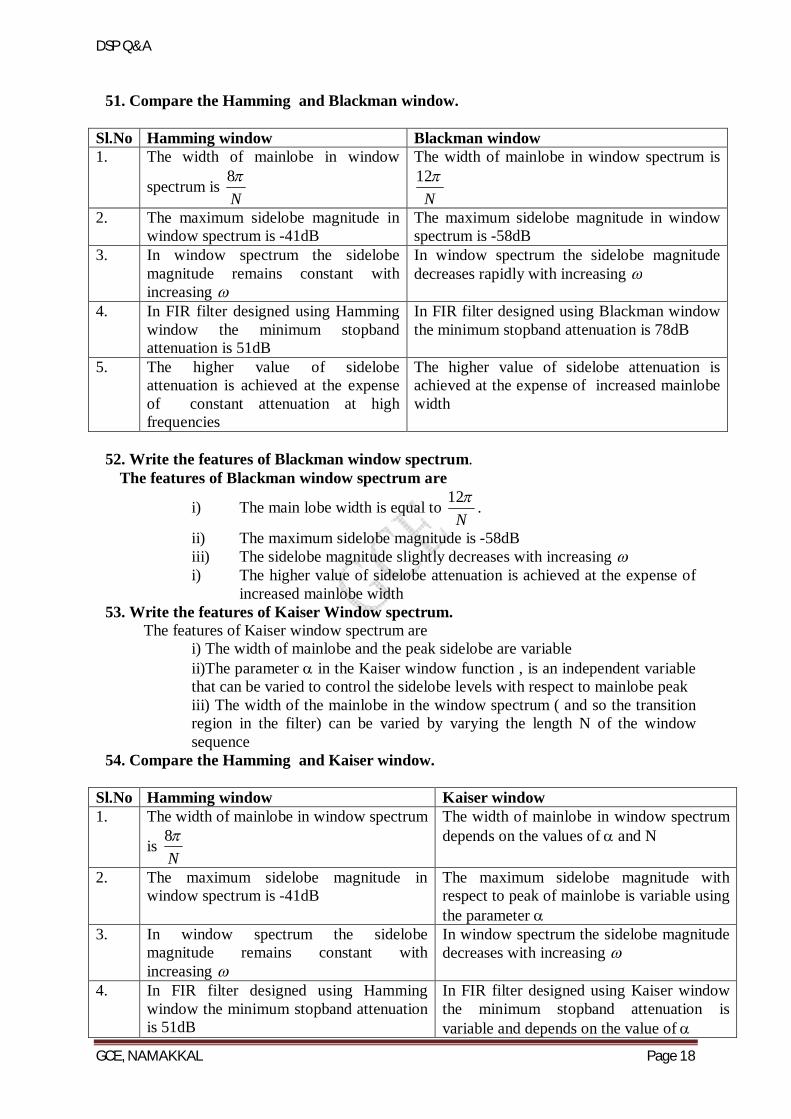
51. Compare the Hamming and Blackman window.
Sl.No Hamming window Blackman window 1. The width of mainlobe in window
spectrum is N8
The width of mainlobe in window spectrum is
N12
2. The maximum sidelobe magnitude in window spectrum is -41dB
The maximum sidelobe magnitude in window spectrum is -58dB
3. In window spectrum the sidelobe magnitude remains constant with increasing
In window spectrum the sidelobe magnitude decreases rapidly with increasing
4. In FIR filter designed using Hamming window the minimum stopband attenuation is 51dB
In FIR filter designed using Blackman window the minimum stopband attenuation is 78dB
5. The higher value of sidelobe attenuation is achieved at the expense of constant attenuation at high frequencies
The higher value of sidelobe attenuation is achieved at the expense of increased mainlobe width
52. Write the features of Blackman window spectrum.
The features of Blackman window spectrum are
i) The main lobe width is equal to N12
.
ii) The maximum sidelobe magnitude is -58dB iii) The sidelobe magnitude slightly decreases with increasing i) The higher value of sidelobe attenuation is achieved at the expense of
increased mainlobe width 53. Write the features of Kaiser Window spectrum.
The features of Kaiser window spectrum are i) The width of mainlobe and the peak sidelobe are variable
ii)The parameter in the Kaiser window function , is an independent variable that can be varied to control the sidelobe levels with respect to mainlobe peak iii) The width of the mainlobe in the window spectrum ( and so the transition region in the filter) can be varied by varying the length N of the window sequence
54. Compare the Hamming and Kaiser window.
Sl.No Hamming window Kaiser window 1. The width of mainlobe in window spectrum
is N8
The width of mainlobe in window spectrum depends on the values of and N
2. The maximum sidelobe magnitude in window spectrum is -41dB
The maximum sidelobe magnitude with respect to peak of mainlobe is variable using the parameter
3. In window spectrum the sidelobe magnitude remains constant with increasing
In window spectrum the sidelobe magnitude decreases with increasing
4. In FIR filter designed using Hamming window the minimum stopband attenuation is 51dB
In FIR filter designed using Kaiser window the minimum stopband attenuation is variable and depends on the value of
DSP Q&A
GCE, NAMAKKAL Page 19
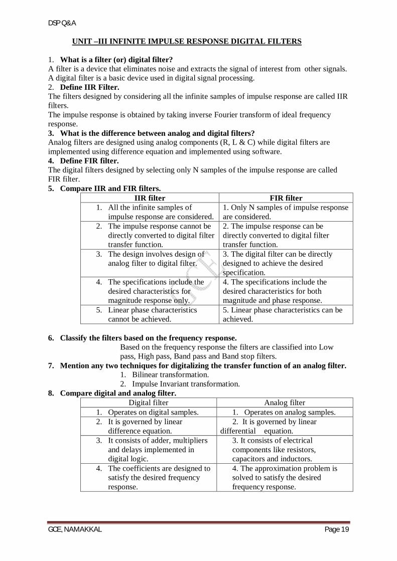
UNIT –III INFINITE IMPULSE RESPONSE DIGITAL FILTERS 1. What is a filter (or) digital filter? A filter is a device that eliminates noise and extracts the signal of interest from other signals. A digital filter is a basic device used in digital signal processing. 2. Define IIR Filter. The filters designed by considering all the infinite samples of impulse response are called IIR filters. The impulse response is obtained by taking inverse Fourier transform of ideal frequency response. 3. What is the difference between analog and digital filters? Analog filters are designed using analog components (R, L & C) while digital filters are implemented using difference equation and implemented using software. 4. Define FIR filter. The digital filters designed by selecting only N samples of the impulse response are called FIR filter. 5. Compare IIR and FIR filters.
IIR filter FIR filter 1. All the infinite samples of
impulse response are considered. 1. Only N samples of impulse response are considered.
2. The impulse response cannot be directly converted to digital filter transfer function.
2. The impulse response can be directly converted to digital filter transfer function.
3. The design involves design of analog filter to digital filter.
3. The digital filter can be directly designed to achieve the desired specification.
4. The specifications include the desired characteristics for magnitude response only.
4. The specifications include the desired characteristics for both magnitude and phase response.
5. Linear phase characteristics cannot be achieved.
5. Linear phase characteristics can be achieved.
6. Classify the filters based on the frequency response.
Based on the frequency response the filters are classified into Low pass, High pass, Band pass and Band stop filters.
7. Mention any two techniques for digitalizing the transfer function of an analog filter. 1. Bilinear transformation. 2. Impulse Invariant transformation.
8. Compare digital and analog filter. Digital filter Analog filter
1. Operates on digital samples. 1. Operates on analog samples. 2. It is governed by linear
difference equation. 2. It is governed by linear differential equation.
3. It consists of adder, multipliers and delays implemented in digital logic.
3. It consists of electrical components like resistors, capacitors and inductors.
4. The coefficients are designed to satisfy the desired frequency response.
4. The approximation problem is solved to satisfy the desired frequency response.
DSP Q&A
GCE, NAMAKKAL Page 20
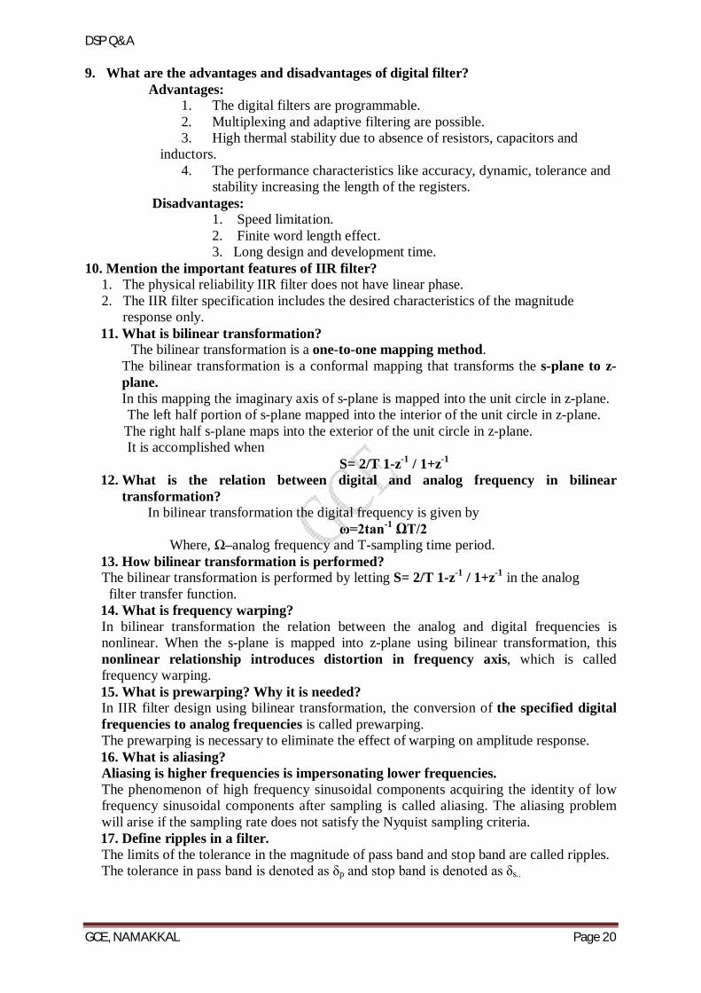
9. What are the advantages and disadvantages of digital filter? Advantages:
1. The digital filters are programmable. 2. Multiplexing and adaptive filtering are possible. 3. High thermal stability due to absence of resistors, capacitors and
inductors. 4. The performance characteristics like accuracy, dynamic, tolerance and
stability increasing the length of the registers. Disadvantages:
1. Speed limitation. 2. Finite word length effect. 3. Long design and development time.
10. Mention the important features of IIR filter? 1. The physical reliability IIR filter does not have linear phase. 2. The IIR filter specification includes the desired characteristics of the magnitude
response only. 11. What is bilinear transformation?
The bilinear transformation is a one-to-one mapping method. The bilinear transformation is a conformal mapping that transforms the s-plane to z- plane. In this mapping the imaginary axis of s-plane is mapped into the unit circle in z-plane.
The left half portion of s-plane mapped into the interior of the unit circle in z-plane. The right half s-plane maps into the exterior of the unit circle in z-plane. It is accomplished when S= 2/T 1-z-1 / 1+z-1
12. What is the relation between digital and analog frequency in bilinear transformation?
In bilinear transformation the digital frequency is given by ω=2tan-1 ΩT/2
Where, Ω–analog frequency and T-sampling time period. 13. How bilinear transformation is performed? The bilinear transformation is performed by letting S= 2/T 1-z-1 / 1+z-1 in the analog filter transfer function. 14. What is frequency warping? In bilinear transformation the relation between the analog and digital frequencies is nonlinear. When the s-plane is mapped into z-plane using bilinear transformation, this nonlinear relationship introduces distortion in frequency axis, which is called frequency warping. 15. What is prewarping? Why it is needed? In IIR filter design using bilinear transformation, the conversion of the specified digital frequencies to analog frequencies is called prewarping. The prewarping is necessary to eliminate the effect of warping on amplitude response. 16. What is aliasing? Aliasing is higher frequencies is impersonating lower frequencies. The phenomenon of high frequency sinusoidal components acquiring the identity of low frequency sinusoidal components after sampling is called aliasing. The aliasing problem will arise if the sampling rate does not satisfy the Nyquist sampling criteria. 17. Define ripples in a filter. The limits of the tolerance in the magnitude of pass band and stop band are called ripples. The tolerance in pass band is denoted as δp and stop band is denoted as δs..
DSP Q&A
GCE, NAMAKKAL Page 21
18. Why the aliasing is absent in bilinear transformation? Because the bilinear mapping is one-to-one mapping and so there is no effect of aliasing present in BT. 19. What are the advantages and disadvantages of bilinear transformation?
Advantages: 1. It is one-to-one mapping method. 2. There is no aliasing. 3. The effect of warping on amplitude response can be eliminated by prewarping the
analog filter. 4. It is used to design digital filters with prescribed magnitude response with piecewise
constant values. Disadvantages: 1. The nonlinear relationship between the analog to digital frequencies introduces
frequency distortion which is called frequency warping. 2. A linear phase analog filter cannot be transformed to a linear digital filter.
20. Compare the impulse invariant transformation and bilinear transformation.
Impulse invariant transformation Bilinear transformation 1. It is many-to-one method. 1. It is one-to-one method. 2. Aliasing effect is present. 2. Aliasing effect is not present. 3. No frequency warping effect. 3. Frequency warping effect is
present. 4. It is not suitable for high pass
and band reject filter designs. 4. It is suitable for high pass and band reject filter designs.
5. Only poles of the system can be mapped.
5.Poles as well as zeros can be mapped.
6. It is accomplished by applying practical fraction expansion method .
4.it is accomplished when applying S= 2/T 1-z-1 / 1+z-1.
21. What is impulse invariant transformation?
The transformation of analog filter to digital filter without modifying the impulse response of the filter is called impulse invariant transformation. 22. What is the importance of poles in filter design?
The stability of a filter is related to the location of the poles. For a stable analog filter the poles should lie on the left of s-plane. For a stable digital filter the poles should lie inside the unit circle in the z-plane.
23. Why an Impulse Invariant Transformation is not considered to be one-to-one?
In impulse invariant transformation any strip of width 2π /T in the s-plane for values of s in the range (2k-1)/T ≤ Ω ≤ (2k+1) is mapped into the entire z-plane. The left half portion of each strip in s-plane maps into the interior of the unit circle in z-plane. The right half portion of each strip in s-plane maps into the exterior of the unit circle in z-plane. The imaginary of each strip in s-plane maps into the unit circle in z-plane. Hence the impulse invariant transformation is many-to-one.
24. What is the relation between digital and analog frequency in IIT? Digital frequency ω = Ω T Where, Ω – analog frequency and T-sampling time period.
DSP Q&A
GCE, NAMAKKAL Page 22
25. Why impulse invariant transformation method is not preferred in the design of
IIR filter other than low pass filter? In impulse invariant transformation method, the mapping from s-plane to z-plane is
many to one. Thus there is an infinite number of poles that map to the same location in the z-plane so it produce aliasing effect. That is why the IIT is not preferred in the design of IIR filter other than low pass filters. 26. What is butterworth approximation?
In butterworth approximation, the error function is selected such that the magnitude is maximally flat in the origin and monotonically decreasing with increasing Ω. 27. What is chebyshev approximation?
In chebyshev approximation, the approximation function is selected such that the error is minimized over a prescribed band of frequencies. 28. Write the properties of butterworth filter.
1. The butterworth filters are all pole designs. 2. At the cutoff frequency, the magnitude of normalized butterworth filter is 1/√2. 3. The magnitude is maximally flat in the origin and monotonically decreasing with
increasing Ω. 4. The filter order N, completely specifies the filter and as the value of N increases
the magnitude response approaches the ideal response. 29. Write the properties of chebyshev filter.
1. The chebyshev filters are all poles designs. 2. The normalizing magnitude function has a value of 1/√1+ε2. 3. The magnitude response is equipple in the passband and monotonic in the
stopband. 4. The magnitude response approaches the ideal response as the value of N increases.
30. What are the requirements for converting a stable analog filter into a stable digital filter?
The JΩ axis in the s plane should be map into the unit circle in the Z plane .thus there will be a direct relationship between the two frequency variables in the two domains
The left half plane of the s plane should be map into the inside of the unit circle in the z –plane .thus the stable analog filter will be converted to a stable digital filter
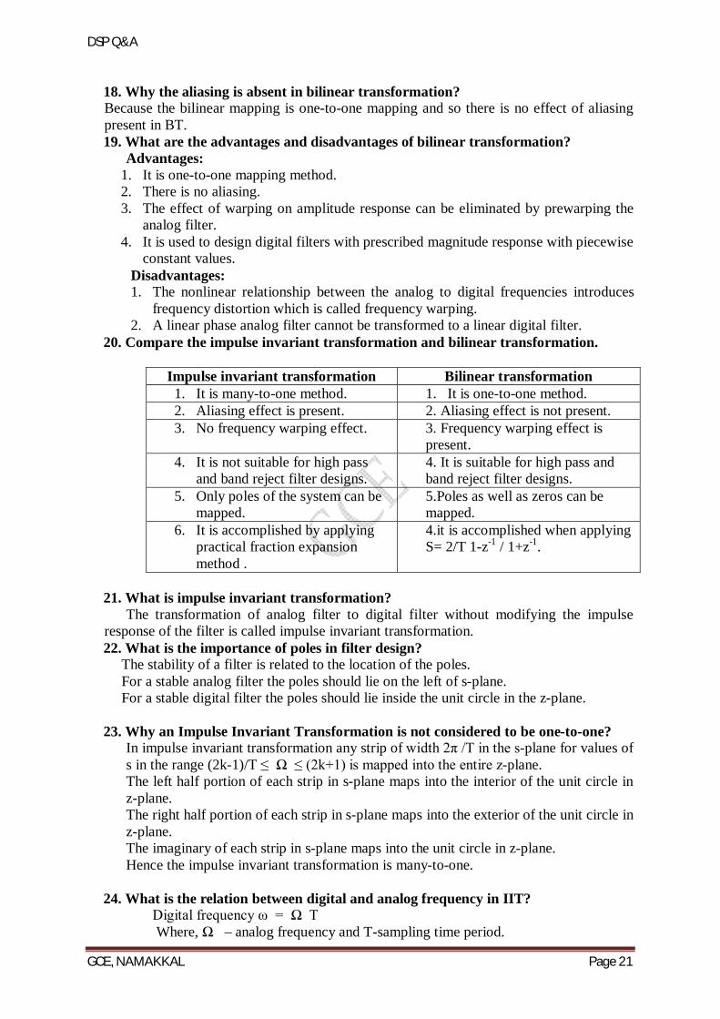
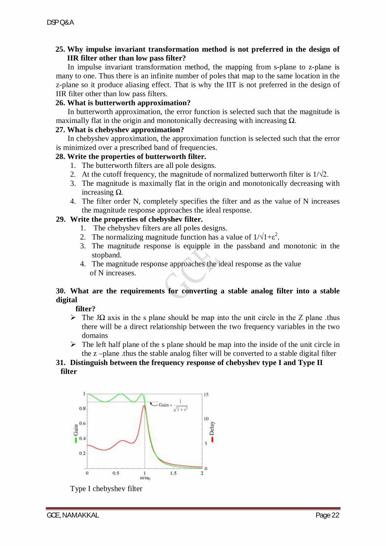
31. Distinguish between the frequency response of chebyshev type I and Type II filter
Type I chebyshev filter
DSP Q&A
GCE, NAMAKKAL Page 23
Type II chebyshev filter Type I chebyshev filters are all pole filters that exhibit equirpple behavior in the pass band and monotonic in stop band .Type II chebyshev filters contain both poles and zeros and exhibits a monotonic behavior in the pass band and an equiripple behavior in the stop band
32. What is the need for prewraping in the design of IIR filter The warping effect can be eliminated by prewarping the analog filter .This can be
done by finding prewarping analog frequencies using the formula Ω = 2tan-1ΩT/2
33. Write frequency translation for BPF from LPF Low pass with cut – off frequency ΏC to band –pass with lower cut-off frequency Ώ1 and
higher cut-off frequency Ώ2: S ------------- ΏC (s2 + Ώ1 Ώ2) / s (Ώ2 - Ώ1)
The system function of the high pass filter is then H(s) = Hp ΏC ( s2 + Ώ1 Ώ2) / s (Ώ2 - Ώ1)
34. What are the different types of structures for realization of IIR systems? The different types of structures for realization of IIR system are (i) Direct form I structure (ii) Direct form II structure (iii) Cascade form structure (iv) Parallel form structure (v) Lattice – ladder form structure.
35. Distinguish between recursive realization and non-recursive realization. For recursive realization the current output y(n) is a function of past outputs, past and present inputs. This form corresponds to an Infinite – Impulse response (IIR) digital filter. For non-recursive realizations current output sample y(n) is a function of only past and present inputs. This form corresponds to a Finite Impulse response (FIR) digital filter.
36. How many number of additions, multiplications and memory locations are required to realize a system H(z) having M zeros and N poles in (a) Direct form – I realization (b) Direct form – II realization. (a) The Direct form – I realization requires M+N+1 multiplications, M+N additions and M + N + 1 memory locations. (b) The Direct form – II realization requires M+N+1 multiplication, M+N additions and the maximum of (M, N) memory locations.
37. What is the main advantage of Direct form- II realizations when compared to Direct form –I realization?
In Direct form – II realization, the number of memory locations required is less than that of Direct form – I realization.
DSP Q&A
GCE, NAMAKKAL Page 24
38. Define signal flow graph. A signal flow graph is defined as a graphical representation of the relationship
between the variables of a set of linear difference equations.
39. What is transposed theorem and transposed structure? The transpose of a structure is defined by the following operations. (i)Reverse the directions of all branches in the signal flow graph (ii) Interchange the input and outputs
(iii)Reverse the roles of all nodes in the flow graph (iv)Summing points become branching points (v) Branching points become summing points
According to transposition theorem if we reverse the directions of all branch transmittance and interchange the input and output in the flow graph, the system function remains unchanged.
40. What is Canonic form structure? The Direct form –II realization requires minimum number of delays for the realization of the system. Hence it is called as “Canonic form” structure.
41. What is the main disadvantage of direct form realization? The Direct form realization is extremely sensitive to parameter quantization. When the order of the system N is large, a small change in a filter coefficient due to parameter quantization, results in a large change in the location of the poles and zeros of the system.
42. What is the advantage of cascade realization? Quantization errors can be minimized if we realize an LTI system in cascade form.
43. What are the different types of filters based on impulse response? Based on impulse response the filters are of two types 1. IIR filter 2. FIR filter
The IIR filters are of recursive type, whereby the present output sample depends on the present input, past inputs samples and output samples. The FIR filters are of non recursive type whereby the present output sample is depends on the present input sample and previous input samples.
44. What is the general form of IIR filter? The most general form of IIR filter can be written as
N
kk
M
k
kk
a
zbzH
1
0
1)(
45. Give the magnitude of Butterworth filter. What is the effect of varying order of N on magnitude and phase response?
The magnitude function of the Butterworth filter is given by
..............3,2,1
1
1)(21
2
NjHN
c
DSP Q&A
GCE, NAMAKKAL Page 25
Where N is the order of the filter and c is the cut off frequency. The magnitude response of the Butterworth filter closely approximates the ideal response as the order N increases. The phase response becomes more non-linear as N increases.
46. Give any two properties of Butterworth low pass filters.
1. The magnitude response of the Butterworth filter decreases monotonically as the frequency increases from 0 to α
2. The magnitude response of the Butterworth filter closely approximates the ideal response as the order N increases
3. The Butterworth filters are all pole designs 4. The poles of the Butterworth filter lies on a circle 5. At the cut off frequency c , the magnitude of normalized Butterworth filter is
21
47. How the poles of Butterworth transfer function are located in s- plane?
The poles of the normalized Butterworth transfer function symmetrically lies
on a unit circle in s-plane with angular spacing ofN .
48. What is Type –1 Chebyshev approximation? In type –1 Chebyshev approximation, the error function is selected such that, the magnitude response is equiripple in the pass band and monotonic in the stop band.
49. What is Type –2 Chebyshev approximation?
In type –2 Chebyshev approximation, the error function is selected such that, the magnitude response is monotonic in pass band and equiripple in the stop band. The Type -2 magnitude response is called inverse Chebyshev response.
50. Write the magnitude function of Chebyshev lowpass filter. The magnitude response of Type -1 lowpass Chebyshev filter is given by
cN
a
C
H221
1
where is attenuation constant and
cNC is the Chebyshev polynomial of the first kind of degree N
51. How the order of the filter affects the frequency response of Chebyshev filter.
From the magnitude response of Type -1 Chebyshev filter it can be observed that the magnitude response approaches the ideal response as the order of the filter is increased.
DSP Q&A
GCE, NAMAKKAL Page 26
52. How will you determine the order N of Chebyshev filter. The order N of the Chebyshev filter is given by
p
s
N1
1
cosh
cosh
where
110 1.0 p 110 1.0 s
53. Compare the Butterworth and Chebyshev Type -1 filter. Sl.No Butterworth filter Chebyshev filter 1. All pole design All pole design 2. The poles lie on a circle in s-plane The poles lie on a ellipse in s-plane 3. The magnitude response is
maximally flat at the origin and monotonically decreasing function of .
The magnitude response is equiripple in pass band and monotonically decreasing in the stop band.
4. The normalized magnitude response
has a value of 2
1 at the cut off
frequency c .
The normalized magnitude response has
a value of 21
1
at the cut off
frequency c . 5. Only few parameters have to be
calculated to determine the transfer function.
A large number of parameter has to be calculated to determine the transfer function.
UNIT IV-FINITE WORD LENGTH EFFECTS
1. Compare fixed point and floating point arithmetic.
Fixed Point Arithmetic Floating Point Arithmetic 1.Fast Operation Slow Operation 2.Relatively economical More expensive because of
costlier hardware 3.Small dynamic range Increased dynamic range 4.Round off error occur only for additions
Round off errors can occur with both additions and multiplication
5.Overflow occur in addition Overflow does not arise 6.Used in small computers Used in larger, general purpose
computers
2. What are the errors that arise due to truncation in floating point numbers 1.Quantization error 2.Truncation error Et=Nt-N
DSP Q&A
GCE, NAMAKKAL Page 27
3. List errors due to finite world length in filter design Input quantization error Product quantization error
Coefficient quantization error
4. What do you mean by limit cycle oscillations in digital filter? In recursive system the nonlinearities due to the finite precision arithmetic operations often cause periodic oscillations to occur in the output ,even when the input sequence is zero or some non zero constant value .such oscillation in recursive system are called limit cycle oscillation
5. Define truncation error for sign magnitude representation and for 2’s
complement Representation
Truncation is a process of discarding all bits less significant than least significant bit that is retained For truncation in floating point system the effect is seen only in mantissa.if the mantissa is truncated to b bits ,then the error satisfies 0≥ > -2.2-b for x >0 and 0≤ < -2.2-b for x <0
6. What are the types of limit cycle oscillation? i.Zero input limit cycle oscillation
ii.overflow limit cycle oscillation 7. What is meant by overflow limit cycle oscillations? In fixed point addition, overflow occurs due to excess of results bit, which are stored at the registers. Due to this overflow, oscillation will occur in the system. Thus oscillation is called as an overflow limit cycle oscillation.
8. How will you avoid Limit cycle oscillations due to overflow in addition
Condition to avoid the Limit cycle oscillations due to overflow in addition |a1|+|a2|<1 a1 and a2 are the parameter for stable filter from stability triangle.
9. What are the different quantization methods? amplitude quantization vector quantization scalar quantization
10. List the advantages of floating point arithmetic. Large dynamic range Occurrence of overflow is very rare Higher accuracy
11. Give the expression for signal to quantization noise ratio and calculate the improvement with an increase of 2 bits to the existing bit.
SNRA / D = 16.81+6.02b-20log10 (RFS /σx) dB. With b = 2 bits increase, the signal to noise ratio will increase by 6.02 X 2 = 12dB.
12. What is truncation error? Truncation is an approximation scheme wherein the rounded number or digits after the pre-defined decimal position are discarded.
13. What are decimators and interpolators? Decimation is a process of reducing the sampling rate by a factor D, i.e., down-sampling. Interpolation is a process of increasing the sampling rate by a factor I, i.e., up-sampling.
DSP Q&A
GCE, NAMAKKAL Page 28
14. What is the effect of down sampling on the spectrum of a signal?
The signal (n) with spectrum X(ω) is to be down sampled by the factor D. The spectrum X(ω) is assumed to be non-zero in the frequency interval 0≤|ω|≤π.
15. Give the rounding errors for fixed and floating point arithmetic. A number x represented by b bits which results in bR after being Rounded
off. The quantized error εR due to rounding is given by εR=QR(x)-x
where QR(x) = quantized number(rounding error) The rounding error is independent of the types of fixed point arithmetic, since it involves the magnitude of the number. The rounding error is symmetric about zero and falls in the range.
-((2-bT-2-b)/2)≤ εR ≤((2-bT-2-b)/2) εR may be +ve or –ve and depends on the value of x.
The error εR incurred due to rounding off floating point number is in the range -2E.2-bR/2)≤ εR ≤2E.2-bR/2
16. Define the basic operations in multirate signal processing. The basic operations in multirate signal processing are
(i)Decimation (ii)Interpolation
Decimation is a process of reducing the sampling rate by a factor D, i.e., down-sampling. Interpolation is a process of increasing the sampling rate by a factor I, i.e., up-sampling.
17. Define sub band coding of speech. Sub band coding of speech is a method by which the speech signal is subdivided into several frequency bands and each band is digitally encode separately. In the case of speech signal processing, most of its energy is contained in the low frequencies and hence can be coded with more bits then high frequencies.
18. What is the effect of quantization on pole locations? N
D(z) = Π (1-pkz-1) k=1
pk is the error or perturbation resulting from the quantization of the filter coefficients
19. What is an anti-imaging filter? The image signal is due to the aliasing effect. In caseof decimation by M, there will be M-1 additional images of the input spectrum. Thus, the input spectrum X(ω) is band limited to the low pass frequency response. An anti-aliasing filter eliminates the spectrum of X(ω) in the range (л/D≤ ω ≤π.
The anti-aliasing filter is LPF whose frequency response HLPF(ω) is given by HLPF(ω) = 1, |ω|≤ л/M = 0, otherwise. D Decimator
20. What is a decimator? If the input to the decimator is x(n)=1,2,-1,4,0,5,3,2, What is the
output? Decimation is a process of reducing the sampling rate by a factor D, I.e., down-sampling. x(n)=1,2,-1,4,0,5,3,2 D=2 Output y(n) = 1,-1,0,3
DSP Q&A
GCE, NAMAKKAL Page 29
21. What is dead band? In a limit cycle the amplitude of the output are confined to a range of value, which is called dead band.
22. How can overflow limit cycles be eliminated? Saturation Arithmetic Scaling
23. What is meant by finite word length effects in digital filters? The digital implementation of the filter has finite accuracy. When numbers
are represented in digital form, errors are introduced due to their finite accuracy. These errors generate finite precision effects or finite word length effects.
When multiplication or addition is performed in digital filter, the result is to be represented by finite word length (bits). Therefore the result is quantized so that it can be represented by finite word register. This quantization error can create noise or oscillations in the output. These effects are called finite word length effects.
24. What are the different types of arithmetic in digital systems? There are three types of arithmetic used in digital systems are
1.Fixed point arithmetic 2. Floating point arithmetic 3. Block Floating arithmetic
25. What do you understand by a fixed-point number?
In fixed-point arithmetic the positions of the binary point is fixed. The bits to the
right represent the fractional part of the number and those to the left represent the integer part. For example, the binary number 01.1100 has the value 1.75 in decimal.
26. What is meant by block floating point representation? What are its
advantages?
In block floating point arithmetic the set of signals to be handled is divided into blocks. Each block has the same value for the exponent. The arithmetic operations with in the block uses fixed point arithmetic and only one exponent per block is stored thus saving memory. This representation of numbers is most suitable in certain FFT flow graphs and in digital audio applications.
27. What are the advantages of floating point arithmetic?
The advantages of floating point arithmetic are
1.Larger dynamic range 2.Overflow in floating point representation is unlikely.
28. Brief on coefficient inaccuracy. (or)
What is coefficient quantization error? What is its effect? The filter coefficients are computed to infinite precision in theory. But, in digital computation the filter coefficients are represented in binary and are stored in registers. If a b bit register is used, the filter coefficients must be rounded or truncated to b bits, which produces an error.
DSP Q&A
GCE, NAMAKKAL Page 30
Due to quantization of coefficients, the frequency response of the filter may differ appreciably from the desired response and some times the filter may actually fail to meet the desired response and some times the filter may actually fail to meet the desired specifications. If the poles of desired filter are close to the unit circle, then those of the filter with quantized coefficients may lie just outside the unit circle, leading to unstability
29. What is product quantization error (or) What is product round off error in
DSP?
Product quantization errors arise at the output of a multiplier. Multiplication of a b bit data with a b bit coefficient results a product having 2b bits. Since a b bit register is used, the multiplier output must be rounded or truncated to b bits, which produces an error. This error is known as product quantization error.
30. What do you understand by input quantization error?
In DSP, the continuous time input signals are converted into digital using a b
bit ADC. The representation of continuous signal amplitude by a fixed digit produce an error, which is known as input quantization error.
31. What is truncation?
Truncation is process of reducing the size of binary number by discarding all bits
less significant than the least significant bit that is retained. (In the truncation of a binary number to b bits all the less significant bits beyond bth bit are discarded)
32. What is rounding?
Round is the process of reducing the size of a binary number to finite word size of
b bits such that, the rounded b-bit number is closest to the original unquantized number.
33. What is Quantization step size?
In digital systems, the numbers are represented in binary. With b-bit binary we
can generate 2b different binary codes. Any range of analog value to be represented in binary should be divided into 2b levels with equal increment. The 2b levels are called Quantization levels and the increment in each level is called Quantization step size . It R is the range of analog signal then,
Quantization step size, q = R/2b.
34. What are limit cycle?
In recursive systems when the input is zero or some nonzero constant value, the nonlinearities due to finite precision arithmetic operations may cause periodic oscillations in the output. These oscillations are called limit cycle.
DSP Q&A
GCE, NAMAKKAL Page 31
35. What is zero input limit cycle?
In recursive system, the product Quantization may create periodic oscillations in the output. These oscillations are called limit cycles. If the system output enters a limit cycle, it will continue to remain in limit cycle even when the input is made zero. Hence these limit cycles are also called zero input limit cycles.
36. What are the three quantization errors due to finite word length registers in
digital filters? The three quantization errors due to finite word length registers in digital filters are
1. Input quantization error 2. Coefficient quantization error 3. Product quantization error
37. How the multiplication and addition are carried out in floating point
arithmetic?
In floating point arithmetic, multiplications are carried out as follows Let f1 = M1 x 2c1 and f2 = M2 x 2c2. Then f3 = f1x f2 = (M1xM2)2(c1+c2)
That is, mantissas are multiplied using fixed point arithmetic and the exponents are added. The sum of two floating point numbers is carried out by shifting the bits of the mantissa of the smaller number to the right until the exponents of the two number are equal and then adding the mantissas.
38. How the system output can be brought out of limit cycle?
The system output can be brought out of limit cycle by applying an input of large magnitude, which is sufficient to drive the system out of limit cycle.
39. What is overflow limit cycle?
In fixed point addition the overflow occurs when the sum exceeds the finite word length of the register used to store the sum. The overflow in addition may lead to oscillations in the output which is called overflow limit cycle.
40. What is saturation arithmetic?
In saturation arithmetic when the result of arithmetic operations exceeds the dynamic range of number system, then the result is set to maximum or minimum possible value. If the upper limit is exceeded then the result is set to maximum possible value. If the lower limit is exceeded then the result is set to minimum possible value.
41. What is meant by Finite word length effect?
The fundamental operations in digital filters are multiplication and addition. When these operations are performed in a digital system the input data as well as the product and sum have to be represented in finite word length, which depends on the size of the register used to store the data.
In digital computation the input and output data are quantized by rounding and truncation toconvert them to a finite word size. This creates an error in the output or creates oscillations in the output. These effects due to finite precision representation of the number in a digital system are called Finite Word Length.
DSP Q&A
GCE, NAMAKKAL Page 32
42. List some of the finite word length effects in digital filters. 1. Errors due to the quantization of input data. 2. Errors due to the quantization of filter co-efficients. 3. Errors due to the quantization of rounding the product in multiplications. 4. Errors due to over flow in addition. 5. Limit cycles.
43. What are the different formats of fixed point representation?
In fixed point representation there are three different formats for representing the binary numbers. 1. Sign-Magnitude format. 2. One’s –Complement format. 3. Two’s –Complement format In all the above three formats the positive number is same but they differ only in representing the negative numbers
44. What is meant by Coefficient quantization error? In the realization of FIR and IIR filters the location of poles and zeros of digital filters directly depends on the value of coefficients. The quantization of the filter coefficient will modify the value of poles and zeros and so the location of the poles and zeros will be shifted from the desired location. This will create deviations in the frequency response of the system. So that the system fail to met the actual frequency response specifications. If the poles of the desired filter are close to the unit circle, then those of the filter with quantized coefficient may lie just outside the unit circle. 45. What is meant by product quantization error?
In digital computations, the output of multipliers i.e. the products are quantized to finite word length in order to store them in registers and to be used in subsequent calculations. The error due to the quantization of the output of multiplier is referred to as product quantization error. 46. Define Noise Transfer Function (NTF). The Noise Transfer Function (NTF) is defined as the transfer function from the noise source to the filter output. The NTF depends on the structure of the digital network.23
47. What are the types of limit cycle? (Or) what are the two kinds of limit cycle
behavior in DSP? There are two types of limit cycle, 1. Zero input limit cycle. 2. Overflow limit cycle
48. Why scaling is need in the digital filter implementation? (Or) what is the need for scaling in the digital filter implementation?
To prevent overflow, the signal level at certain points in the digital filter must be scaled so that no overflow occurs in the adder.
49. How overflow limit cycles can be eliminated? (Or) what are the methods used to preventoverflow?
The overflow limit cycles can be eliminated either by using saturation arithmetic or by scaling the input signal to the adder. 50. What is the drawback in saturation arithmetic? The saturation arithmetic introduces nonlinearity in the adder which creates signal distortion.
DSP Q&A
GCE, NAMAKKAL Page 33
UNIT-V DIGITAL SIGNAL PROCESSORS
1. What is meant by Digital Signal Processor? A digital signal processor (DSP) is an integrated circuit designed for high-speed data manipulations, and is used in audio, communications, image manipulation, and other data-acquisition and data-control applications.
2. What are the classification digital signal processors?
The digital signal processors are classified as i. General purpose digital signal processors ii. Special purpose digital signal processors
3. Write some examples for fixed point DSPs.
TMS320C50, TM 320C54, TM 320C55, ADSP-219x, ADSP-219xx.
4. Write some examples for floating point DSPs. TMS320C3x, TMS320C67x, ADSP-21xxx.
5. What are the factors that influence selection of DSPs? The factors that influence selection of DSPs are 1.Architectural features 2.Execution speed 3.Type of arithmetic 4.Word length
6. What are the applications of PDSPs? Digital cell phones, automated inspection, voicemail, motor control, video conferencing, Noise cancellation, Medical imaging, speech synthesis, satellite communication etc.
7. What are the advantages and disadvantages of VLIW architecture?
The advantages of VLIW architecture are 1. Increased performance 2. Better compiler targets 3. Potentially scalable 4. Potentially easier to program 5. Can add more execution units, allow more instruction to be packed into the
VLIW instruction.
The disadvantages of VLIW architecture are 1.New kind of programmer/compiler complexity
2.Program must keep track of instruction scheduling 3.Increased memory use 4.High power consumption 5.Misleading MIPS ratings
DSP Q&A
GCE, NAMAKKAL Page 34
8. What is pipelining? Pipelining a processor means breaking down its instruction into a series of discrete pipeline stages which can be completed in sequence by specialized hardware.
9. What is pipeline depth?
The number of pipeline stages is referred to as the pipeline depth.
10. What is the pipeline depth of TMS320C50, TM 320C54x? TMS320C50 – 4 TM 320C54x – 6
11. What are the different stages in pipelining? The different stages in pipelining are i. the Fetch phase ii. the Decode phase iii. Memory read phase
iv. the Execute phase
12. What are the different buses of TM 320C5x and their functions? The ‘C5x architecture has four buses 1.Program bus (PB) 2.Program address bus (PAB) 3.Data read bus (DB) 4.Data read address bus (DAB) The program bus carriers the instruction code and immediate operands from program memory to the CPU. The program address bus provides address to program memory space for both read and write. The data read bus interconnects various elements of the CPU to data memory spaces. The data read address bus provides the address to access the data memory spaces.
13. List the various registers used with ARAU. The various registers used with ARAU are 1. Eight auxiliary registers (AR0 –AR7) 2. Auxiliary register pointer (ARP)
14. What are the elements used for the control processing unit of ‘c5X? The elements used for the control processing unit of ‘c5X are
1. Central arithmetic logic unit (CALU) 2. Parallel logic unit (PLU) 3. Auxiliary register arithmetic unit (ARAU) 4. Memory mapped registers 5. Program controller
15. What is the function of parallel logic unit? The parallel logic unit is second logic units, which execute logic operations on
data without affecting the contents of accumulator. 16. List the on chip peripherals in ‘c5x.
The on-chip peripherals interfaces connected to the ‘c5x CPU include (i) Clock generator (ii) Hardware timer (iii) Software programmable wait state generators (iv) General purpose I/O pins (v) Parallel I/O ports
DSP Q&A
GCE, NAMAKKAL Page 35
(vi) Serial port interface (vii) Buffered serial port (viii) Time-divisions multiplexed (TDM) serial port (ix) Host port interface (x) User unmaskable interrupts
17. What are the general purpose I/O pins? Branch control input OBI External flag (XF)
18. What are the arithmetic instructions of ‘C5x? ADD, ADDB, ADDC, SUB, SUBB, MPY and MPYU.
19. What are the logical instructions of ‘c5x? AND, ANDB, OR, ORB, XOR and XORB
20. What are the shift instructions? ROR, ROL, ROLB, RORB and BSAR
21. What are load/store instructions? LACB, LACC, LACL, LAMM, LAR, SACB, SACH, SACL and SAR
22. What is meant by Programmable Digital Signal Processor (PDSP)? Programmable Digital Signal Processor (PDSP) is general purpose
microprocessors designed specifically for digital processing applications. They contain special architecture and instruction set as to execute compute –intensive DSP algorithms more efficiently
23. What are the differences between general purpose and special purpose digital
signal processors? (Or) Compare general purpose and special purpose digital signal processors.
S.No General purpose digital signal processors
Special purpose digital signal processors
1. Basically these are high speed microprocessors.
Basically these are low speed microprocessors.
2. It has architecture and instruction set. It is only consist of hardware.
3. It does not use for special purpose applications.
It is designed for specific applications such as PCM and filtering.
4. TMS320C5X,
TMS320C4X,TMS320C67XX examples for general purpose digital signal
Mitel’s channel telephony voice echo canceller (MT 93001) and FFT processor (PDSP 16515A)
DSP Q&A
GCE, NAMAKKAL Page 36
24. Write short notes on Harvard architecture. In Harvard architecture instructions are stored on punched tape and data are stored in relay latches. The architecture physically separated memories for their instructions and data, requiring dedicated buses for each of them. Instructions and operands can therefore be fetched simultaneously. Harvard architecture is capable of simultaneous reading an instruction code and writing a memory or peripheral as part of the execution of the previous instruction. Since it has two memories, it is impossible for the CPU to mistakenly write code into the program memory and therefore compute the code while it is executing. It is less flexible. It needs two independent memory banks. These two resources are not interchangeable. 25. What are the advantages of Harvard architecture? The modified Harvard architecture used DSPs multiport memory that has separate bus systems for program and data memory and input / output peripherals. It allows to access the several memory locations simultaneously, thereby increasing the data throughput between memory and CPU. 26. What is the disadvantages if Harvard architecture?
The multiple bus system increasing complexity of the CPU. 27. What is meant by VLIW architecture?
The Very Long Instruction Word processing increasing the number of instructions that are processed per cycle.
28. What are the advantages of VLIW architecture? 1. Increased performance. 2. Better compiler. 3. Easier to program. 4. Potentially scalable.
29. What are the disadvantages of VLIW architecture? 1. Compiler complexity for new programmer. 2. Increased memory use. 3. High power consumption. 4. Misleading MIPS ratings.
30. What is meant by multiply Accumulate unit (MAC)? DSPs have a specialized instruction that allows them to multiply, add, and
save the result in a single cycle. This instruction is usually called MAC (short for Multiply, Accumulate).
31. What is the use of Fetch phase? The fetch phase (F) in which the instruction in the instruction register is decoded and the address in the program counter is incremented. 32. What is the use of Decode phase? The decode phase (D) in which the instruction in the instruction register is decode and the address in the program counter is incremented. 33. What is the use of Memory read phase? Memory read phase reads the data from the data buses and also write data to the data buses. 34. What is the use of Execute phase?
The instruction currently in the instruction registers and also completes the write process.
35. What is pipeline depth? The number of pipeline stages is referred to as the pipeline depth.

DSP Q&A
GCE, NAMAKKAL Page 37
36. What is Addressing mode in TMS320C50?
1. Immediate addressing. 2. Indirect addressing. 3. Register addressing. 4. Memory mapped register addressing. 5. Direct addressing. 6. Circular addressing mode.
37. Explain the functional block of TMS320C50. TMS320C50 functional block diagram can be divided into four sub blocks they are,
1. Bus structure. 2. Central Processing Unit. 3. On chip Memory. 4. On chip Peripherals.
38. What are the important elements of TMS320C50 architecture? Central Processing Logic Unit (CPLU). Parallel Logic Unit (PLU). Auxiliary Register Arithmetic Unit (ARAU). Program Counter.
39. What is Parallel Logic Unit (PLU)? The parallel Logic Unit is a second logic unit. That executes logic operations on
data without affecting the Contents of the accumulator. 40. What is meant by Index Register (INDX)?
The 16-bit index register (INDX) is used by the ARAU as a step value to modify the address in the ARs during the indirect address. It is can be used to or subtracted from the current AR on any AR update Cycle and also it is used to increment or decrement the address in steps larger than 1.
41. What is meant by Auxiliary Register? The 16-bit Auxiliary Register (AR0-AR7) can be accessed by the CALU and
modified by the ARAU or PLU. The primary function of the ARs is to provide 16-bit address for indirect addressing to data space. The ARs can also be used as general purpose register or counter.
42. Explain about the Program Counter. The C5X has a 16-bit program counter (PC) which contains the address of internal or external program memory used to fetch instructions.
43. List the on- chip peripherals in C5X. The on-chip peripherals interfaces connected to the C5X CPU includes
1. Clock generators. 2. Hardware timer. 3. General purpose I/O pins. 4. Parallel I/O ports. 5. Serial port interface. 6. Host port interface. 7. TDM serial port.
44. What is the use of Circular addressing mode? Circular addressing mode is the sophisticated ‘C5X’ addressing mode. It use in many algorithms such as convolution, correlation and FIR filtering can use circular buffers in memory to implement a sliding widow,
DSP Q&A
GCE, NAMAKKAL Page 38
Five dedicated registers are allocated for implementation of circular addressing, they are
1. CBSR 1 2. CBSR 2 3. CBER 1 4. CBER 2 5. CBCR
The registers CBSR 1 and CBSR 2 are used to load the starting address of circular buffer.
The register CBER 1 and CBER 2 are used to load the starting address of circular buffer.
The register CBCR is used for Enable and disables the circular buffer. 45. Give the classification of TMS320C5X instruction set.
1. Arithmetic instructions. 2. Logical instructions. 3. Shift instructions. 4. Load / Store instructions. 5. Move instructions. 6. Branch and Call instructions. 7. PUSH and POP instructions. 8. RET instructions. 9. Repeat instructions. 10. IN and OUT instructions.
46. Explain about the TMS320C54X architecture. The Texas instrument TMS320C54X is a16-bit fixed point digital signal
processor. It has one program Memory bus, three data memory buses and four address buses and also it is fastest processor in the family runs at 160 MHz
The TMS320C54X DSP also has an on chip bidirectional bus for accessing on chip peripherals. 47. Explain the Overflow Handling in TMS320C54X architecture. The ALU saturation prevents a result from overflowing by keeping the result at a Maximum or Minimum value. This feature is useful for filter calculations. The Logic is enabled when the overflow mode bit (OVM) in status register ST1 is set. If OVM = 0, the accumulators are loaded with the ALU result without modification. If OVM = 1, the accumulators are loaded with either the most positive 32-bit value or the most negative value depending on the direction of the overflow.
48. What are the applications of DSP Systems? Since their introduction to the market, DSPs have found a wide variety of
applications. They are used in everyday hi-fi systems as well as high-end virtual-reality applications. Generally, DSP is not an expensive technology. Some DSP systems are:
i. Hi-Fi Equipment ii. Toys
iii. Videophones iv. Modems v. Phone Systems
vi. 3D Graphics Systems vii. Image Processing Systems