EUTECH INSTRUMENTS · Eutech Instruments Pte Ltd. Blk 55, ... 1.1 Description of Unit ... for...
34
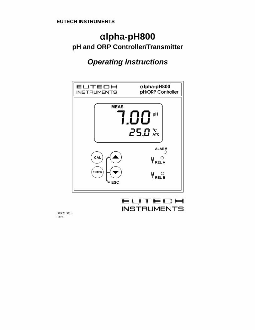
EUTECH INSTRUMENTS αlpha-pH800 pH and ORP Controller/Transmitter Operating Instructions 68X216813 03/99
Transcript of EUTECH INSTRUMENTS · Eutech Instruments Pte Ltd. Blk 55, ... 1.1 Description of Unit ... for...
EUTECH INSTRUMENTS
ααααlpha-pH800pH and ORP Controller/Transmitter
Operating Instructions
68X21681303/99
Preface
Thank you for purchasing the αlpha-pH800 series pH/ORP
controller/transmitter.
This manual serves to explain the use of the αlpha-pH800 series pH/ORP
controller/transmitter. The manual functions in two ways, firstly as a step
by step guide to help the user operate the instrument. Secondly, it serves
as a handy reference guide. This instruction manual is written to cover as
many anticipated applications of the αlpha-pH800 pH/ORP
controller/transmitter. If you have doubts in the use of the instrument,
please do not hesitate to contact the nearest Eutech Instruments’
Authorised Distributor.
The information presented in this manual is subject to change without
notice as improvements are made, and does not represent a commitment
on part of Eutech Instruments Pte Ltd.
Eutech Instruments cannot accept any responsibility for damage or
malfunction of the unit due to improper use of the instrument.
Copyright 1999 Eutech Instruments Pte Ltd. Version 1.0. Allrights reserved.
Eutech Instruments Pte Ltd. Blk 55, Ayer Rajah Crescent #04-14/24,Singapore 139 949. Tel: (65) 778 6876; Fax: (65) 773 0836; e-mail:[email protected]; Home page: http://www.eutechinst.com
TABLE OF CONTENTS
1 INTRODUCTION................................................................................................ 11.1 Description of Unit.................................................................................... 11.2 Applications................................................................................................ 2
2 ASSEMBLY AND INSTALLATIONS............................................................. 32.1 Measurement and Control System........................................................ 32.2 Unit Dimensions ....................................................................................... 3
3 ELECTRICAL CONNECTIONS....................................................................... 43.1 Connection Diagram................................................................................ 43.2 Back Panel ................................................................................................ 6
4 OVERVIEW....................................................................................................... 84.1 Keypad and Display................................................................................. 8Function Groups................................................................................................... 94.2 Control Concept ....................................................................................... 9
5 MEASUREMENT............................................................................................ 105.1 Display in Measurement mode ............................................................ 10
6 CALIBRATION............................................................................................... 116.1 pH Calibration......................................................................................... 116.2 ORP – mV Calibration ........................................................................... 13
7 ADVANCED SET UP MODE......................................................................... 147.1 Electrode Offset (OFS) sub-function ................................................... 147.2 Setting temperature (Set oC) sub-function ......................................... 157.3 Control Relay A/Control Relay B (SP1/SP2) sub-function............... 187.4 Configuration (ConF) sub-function ...................................................... 227.5 Calibration (CAL) sub-function............................................................. 23
8 TECHNICAL SPECIFICATIONS................................................................... 249 ACCESSORIES ............................................................................................... 2510 GENERAL INFORMATION....................................................................... 25
10.1 Warranty.................................................................................................. 2510.2 Packaging ............................................................................................... 2510.3 Return of Goods ..................................................................................... 2610.4 Guidelines for Returning Unit for Repair ............................................ 26
11 APPENDICES.............................................................................................. 2711.1 Appendix 1 .............................................................................................. 2711.2 Appendix 2 .............................................................................................. 2811.3 Appendix 3 .............................................................................................. 29

1
1 INTRODUCTION1.1 Description of UnitThank you for purchasing Eutech’s ¼ DIN alpha-800 series pH/ORP
process controllers. This unit is used for measuring either pH or ORP
parameter one at a time, and the operational mode is switchable from the
menu. You can use this unit to measure pH or ORP with limit control.
This controller has many user-friendly and safety features which include:
• Menu-driven program that simplifies set-up
• Built-in non-volatile memory backup to ensure that calibration and
other information are not erased if power supply fails
• Push-button two-point calibration and electrode offsetadjustment from the keypad
• Automatic temperature compensation (ATC)
• Manual temperature compensation setting without the ATC probe,
with independent setting for calibration and process temperature
• 0 to 2000 second time delay adjustment on all relays – minimise
false alarms
• Separately adjustable high and low set point hysteresis (dead
bands) prevent chattering of relays around the set points
• Asymmetrical/symmetrical input for pH/ORP operation
• Large dual display LCD for easy reading with clear multiple
annunciators, alarm status, operational and error messages
• Two switching contacts as set-point triggering relays
• Hold function freezes output current (4/20mA) and control relays
• LED indicators signal control activities to monitor controller status
from a distance
• Protection against electromagnetic interference – Input and
output are free from external inference
2
1.2 ApplicationsUse this controller in panel mounted enclosures for applications such as
water treatment and monitoring, galvanic-decontamination, chemical
processing food processing, clean or waste water control and
neutralisation process.
3
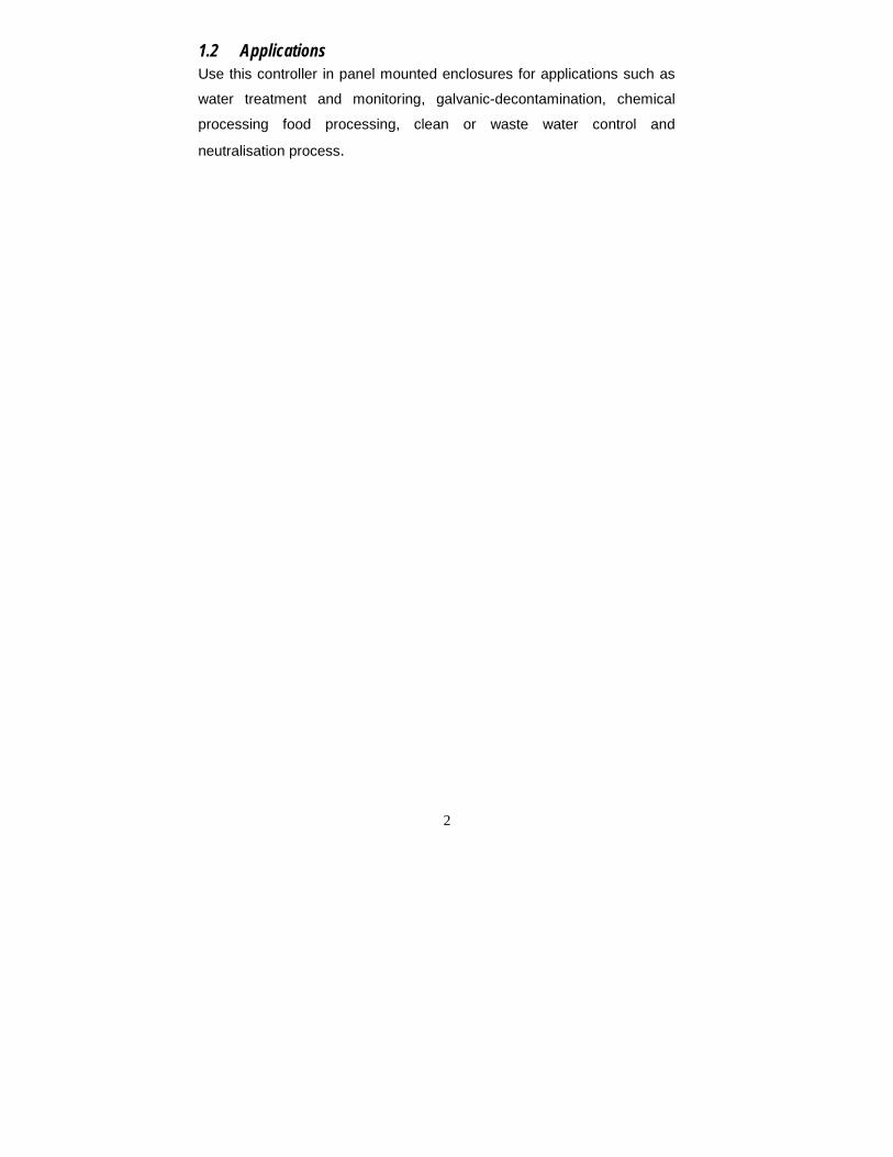
2 ASSEMBLY AND INSTALLATIONS2.1 Measurement and Control SystemA typical measurement system consists of:
• a pH/ORP process controller
• a pH/ORP combination electrode with integrated or separate
temperature sensor Pt 100/1000,
• an immersion, flow or process assembly with or without a potential
matching pin (PMP)
• a final control element such as pump or valve
• a recorder
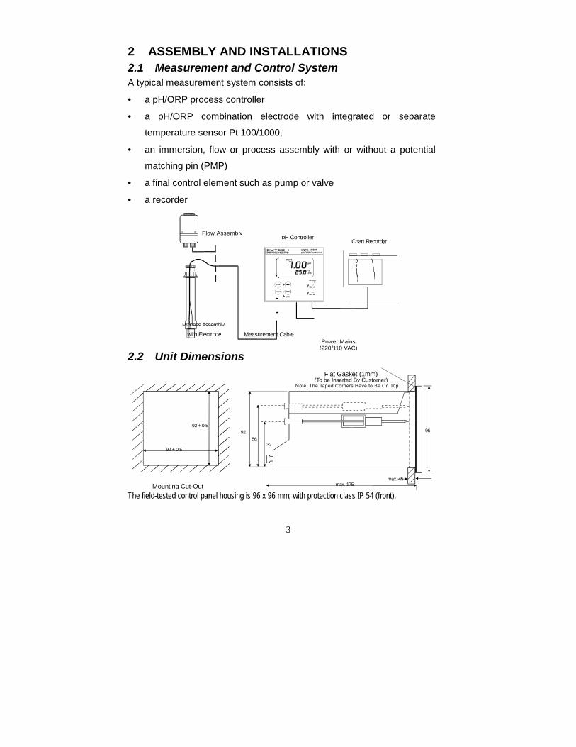
2.2 Unit Dimensions
The field-tested control panel housing is 96 x 96 mm; with protection class IP 54 (front).max. 175
max. 45Mounting Cut-Out
Flat Gasket (1mm)(To be Inserted By Customer)
Note: The Taped Corners Have to Be On Top
92
3256
96
92 + 0.5
92 + 0.5
Power Mains(220/110 VAC)
Flow Assemb
Measurement Cablewith Electrode
erly
Process Assembly
Chart RecordpH Controller
4
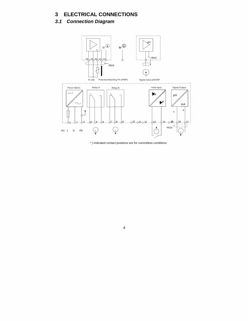
3 ELECTRICAL CONNECTIONS3.1 Connection Diagram
Signal OutputHold InputRelay BRelay APower Mains
pH
mA
- +
PE/SPEAC: NL
1 2 543 6 7 8 9 10 11 12 13 14 15 1715 16
* ) indicated contact positions are for currentless conditions
Pt 100 Potential Matching Pin (PMP) Signal Input pH/ORP
S/V
PE/S
pH
18 19 20 21 22
S/S/
BNC
5
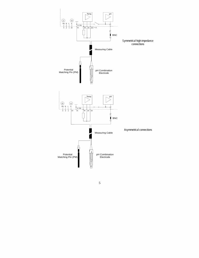
Symmetrical high-impedanceconnections
Asymmetrical connections
Measuring Cable
pH CombinationElectrode
Temp. pH
BNC
0 / PAPE N L S
22 21123 20 19 18
PotentialMatching Pin (PM)
S
Measuring Cable
pH CombinationElectrode
Temp. pH
BNC
0 / PAPE N L S
22 21123 20 19 18
PotentialMatching Pin (PM)
6
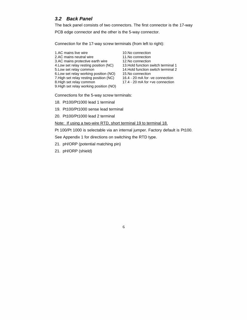
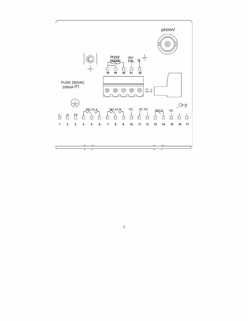
3.2 Back PanelThe back panel consists of two connectors. The first connector is the 17-way
PCB edge connector and the other is the 5-way connector.
Connection for the 17-way screw terminals (from left to right):
1.AC mains live wire 10.No connection2.AC mains neutral wire 11.No connection3.AC mains protective earth wire 12.No connection4.Low set relay resting position (NC) 13.Hold function switch terminal 15.Low set relay common 14.Hold function switch terminal 26.Low set relay working position (NO) 15.No connection7.High set relay resting position (NC) 16.4 - 20 mA for -ve connection8.High set relay common 17.4 - 20 mA for +ve connection9.High set relay working position (NO)
Connections for the 5-way screw terminals:
18. Pt100/Pt1000 lead 1 terminal
19. Pt100/Pt1000 sense lead terminal
20. Pt100/Pt1000 lead 2 terminal
Note: If using a two-wire RTD, short terminal 19 to terminal 18.
Pt 100/Pt 1000 is selectable via an internal jumper. Factory default is Pt100.
See Appendix 1 for directions on switching the RTD type.
21. pH/ORP (potential matching pin)
21. pH/ORP (shield)
7
0V/Pt100/
RELAY A
L N PE
100mA (F)FUSE 250VAC
HOLDRELAY B
Pt1000 PAL S/
NC- +
NC NCNC
8
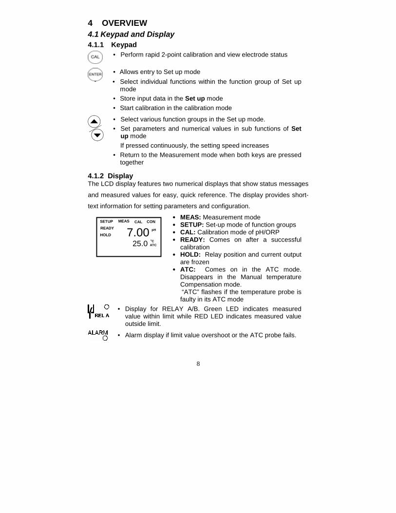
4 OVERVIEW4.1 Keypad and Display4.1.1 Keypad
• Perform rapid 2-point calibration and view electrode status
• Allows entry to Set up mode• Select individual functions within the function group of Set up
mode• Store input data in the Set up mode• Start calibration in the calibration mode
• Select various function groups in the Set up mode.• Set parameters and numerical values in sub functions of Set
up mode If pressed continuously, the setting speed increases• Return to the Measurement mode when both keys are pressed
together
4.1.2 DisplayThe LCD display features two numerical displays that show status messages
and measured values for easy, quick reference. The display provides short-
text information for setting parameters and configuration.
•••• MEAS: Measurement mode•••• SETUP: Set-up mode of function groups•••• CAL: Calibration mode of pH/ORP•••• READY: Comes on after a successful
calibration•••• HOLD: Relay position and current output
are frozen•••• ATC: Comes on in the ATC mode.
Disappears in the Manual temperatureCompensation mode.
“ATC” flashes if the temperature probe isfaulty in its ATC mode
• Display for RELAY A/B. Green LED indicates measuredvalue within limit while RED LED indicates measured valueoutside limit.
• Alarm display if limit value overshoot or the ATC probe fails.
7.00 25.0 ATC
SETUP
HOLD
CALMEAS CONREADY pH
oC
9
Function GroupsThe main function and sub-function groups are organised in a matrix format
for configuration and selection of parameters. The main function groups are:
1) Offset adjustment (OFS)
2) Temperature Measurement / compensation settings (Set oC)
3) Control relay 1 configuration (SP1)
4) Control relay 2 configuration (SP2)
5) Configuration (ConF)
6) Calibration (CAL pH)
4.2 Control ConceptThe main function and sub-function groups are organised in a matrix format
as shown below. These functions can be accessed via the front keypad for
configuration and selection of parameters.
10
5 MEASUREMENT5.1 Display in Measurement modeWhen the controller is initially powered on, it automatically enters into the
Measurement mode after the large dual LCD displays all segments briefly.
The upper display shows the measured pH or ORP value, while the lower
display shows either the temperature value if the controller is set for pH
measurement or “OrP” if it is set for ORP measurement.
Annunciators at the right side of the display indicate whether the controller is
set for pH or mV measurement..
Similarly annunciators or icons at the top or left side of the display shows the
current status of controller, e.g. “MEAS”, “SETUP”, “CAL”, “READY”, etc. In
addition, error messages also guide the user in time of any faulty conditions
as indicated by “ERR” or icons flashing.
5.1.1 Check electrode performanceTo read current electrode slope and offset values:
1) Press the CAL key followed by the ENTER key. The upper display
shows electrode slope. The lower display reading shows the pH reading at 0
mV.
2) Press the ∆∆∆∆ and ∇∇∇∇ keys to return to Measurement mode.
11
6 CALIBRATIONDirect Calibration from the Measurement mode is possible via the CAL key.
The Calibration procedure can also be accessed from the Advanced Setup
mode.
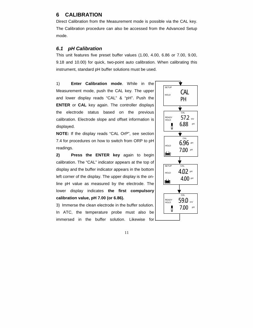
6.1 pH CalibrationThis unit features five preset buffer values (1.00, 4.00, 6.86 or 7.00, 9.00,
9.18 and 10.00) for quick, two-point auto calibration. When calibrating this
instrument, standard pH buffer solutions must be used.
1) Enter Calibration mode. While in the
Measurement mode, push the CAL key. The upper
and lower display reads “CAL” & “pH”. Push the
ENTER or CAL key again. The controller displays
the electrode status based on the previous
calibration. Electrode slope and offset information is
displayed.
NOTE: If the display reads “CAL OrP”, see section
7.4 for procedures on how to switch from ORP to pH
readings.
2) Press the ENTER key again to begin
calibration. The “CAL” indicator appears at the top of
display and the buffer indicator appears in the bottom
left corner of the display. The upper display is the on-
line pH value as measured by the electrode. The
lower display indicates the first compulsorycalibration value, pH 7.00 (or 6.86).3) Immerse the clean electrode in the buffer solution.
In ATC, the temperature probe must also be
immersed in the buffer solution. Likewise for
HOLD 6.96 pH
7.00 pH
CAL
4.02 pH
4.00 pH
SETUP
HOLD
CAL
59.0 mV
7.00 pH
READYHOLD
CAL
CALPH
SETUP
HOLD
57.2 mV
6.88 pH
READYHOLD
CAL
12
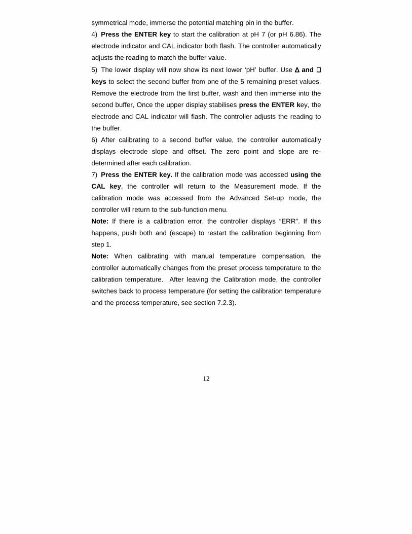
symmetrical mode, immerse the potential matching pin in the buffer.
4) Press the ENTER key to start the calibration at pH 7 (or pH 6.86). The
electrode indicator and CAL indicator both flash. The controller automatically
adjusts the reading to match the buffer value.
5) The lower display will now show its next lower ‘pH’ buffer. Use ∆∆∆∆ and ∇∇∇∇keys to select the second buffer from one of the 5 remaining preset values.
Remove the electrode from the first buffer, wash and then immerse into the
second buffer, Once the upper display stabilises press the ENTER key, the
electrode and CAL indicator will flash. The controller adjusts the reading to
the buffer.
6) After calibrating to a second buffer value, the controller automatically
displays electrode slope and offset. The zero point and slope are re-
determined after each calibration.
7) Press the ENTER key. If the calibration mode was accessed using theCAL key, the controller will return to the Measurement mode. If the
calibration mode was accessed from the Advanced Set-up mode, the
controller will return to the sub-function menu.
Note: If there is a calibration error, the controller displays “ERR”. If this
happens, push both and (escape) to restart the calibration beginning from
step 1.
Note: When calibrating with manual temperature compensation, the
controller automatically changes from the preset process temperature to the
calibration temperature. After leaving the Calibration mode, the controller
switches back to process temperature (for setting the calibration temperature
and the process temperature, see section 7.2.3).
13
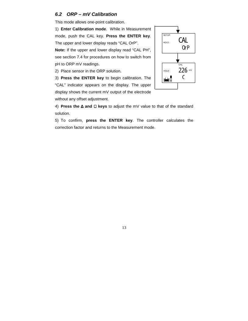
6.2 ORP – mV CalibrationThis mode allows one-point calibration.
1) Enter Calibration mode. While in Measurement
mode, push the CAL key. Press the ENTER key.
The upper and lower display reads “CAL OrP”.
Note: If the upper and lower display read “CAL PH”,
see section 7.4 for procedures on how to switch from
pH to ORP mV readings.
2) Place sensor in the ORP solution.
3) Press the ENTER key to begin calibration. The
“CAL” indicator appears on the display. The upper
display shows the current mV output of the electrode
without any offset adjustment.
4) Press the ∆∆∆∆ and ∇∇∇∇ keys to adjust the mV value to that of the standard
solution.
5) To confirm, press the ENTER key. The controller calculates the
correction factor and returns to the Measurement mode.
CAL OrP
SETUP
HOLD
226 mV
CHOLD
CAL
14
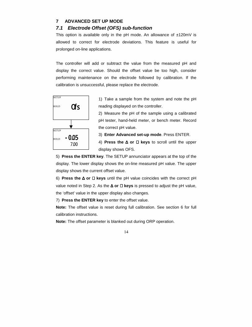
7 ADVANCED SET UP MODE7.1 Electrode Offset (OFS) sub-functionThis option is available only in the pH mode. An allowance of ±120mV is
allowed to correct for electrode deviations. This feature is useful for
prolonged on-line applications.
The controller will add or subtract the value from the measured pH and
display the correct value. Should the offset value be too high, consider
performing maintenance on the electrode followed by calibration. If the
calibration is unsuccessful, please replace the electrode.
1) Take a sample from the system and note the pH
reading displayed on the controller.
2) Measure the pH of the sample using a calibrated
pH tester, hand-held meter, or bench meter. Record
the correct pH value.
3) Enter Advanced set-up mode. Press ENTER.
4) Press the ∆∆∆∆ or ∇∇∇∇ keys to scroll until the upper
display shows OFS.
5) Press the ENTER key. The SETUP annunciator appears at the top of the
display. The lower display shows the on-line measured pH value. The upper
display shows the current offset value.
6) Press the ∆∆∆∆ or ∇∇∇∇ keys until the pH value coincides with the correct pH
value noted in Step 2. As the ∆∆∆∆ or ∇∇∇∇ keys is pressed to adjust the pH value,
the ‘offset’ value in the upper display also changes.
7) Press the ENTER key to enter the offset value.
Note: The offset value is reset during full calibration. See section 6 for full
calibration instructions.
Note: The offset parameter is blanked out during ORP operation.
SETUP
SETUP
HOLD
HOLD
OfsOfsOfsOfs
-0.05-0.05-0.05-0.057.00
15
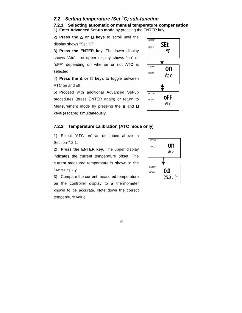
7.2 Setting temperature (Set oC) sub-function7.2.1 Selecting automatic or manual temperature compensation1) Enter Advanced Set-up mode by pressing the ENTER key.
2) Press the ∆∆∆∆ or ∇∇∇∇ keys to scroll until the
display shows “Set oC”.
3) Press the ENTER key. The lower display
shows “Atc”; the upper display shows “on” or
“oFF” depending on whether or not ATC is
selected.
4) Press the ∆∆∆∆ or ∇∇∇∇ keys to toggle between
ATC on and off.
5) Proceed with additional Advanced Set-up
procedures (press ENTER again) or return to
Measurement mode by pressing the ∆∆∆∆ and ∇∇∇∇
keys (escape) simultaneously.
7.2.2 Temperature calibration (ATC mode only)
1) Select “ATC on” as described above in
Section 7.2.1.
2) Press the ENTER key. The upper display
indicates the current temperature offset. The
current measured temperature is shown in the
lower display.
3) Compare the current measured temperature
on the controller display to a thermometer
known to be accurate. Note down the correct
temperature value.
0.00.00.00.025.0 ATC
SETUP
HOLDoC
ononononAtc
SETUP
HOLD
oFFoFFoFFoFFAtc
ononononAtc
SETUP
HOLD
SETUP
SEtSEtSEtSEtooooCCCC
SETUP
HOLD
HOLD
16
4) Press the ∆∆∆∆ or ∇∇∇∇ keys to scroll the lower display to match the correct
value. The upper display will now show the offset value. You can offset
temperature up to ± 5oC.
5) Press the ENTER key to confirm your selection.
6) Continue with additional Advanced Set-up procedures, or return to the
Measurement mode by pressing the ∆∆∆∆ and ∇∇∇∇ keys (escape) simultaneously.
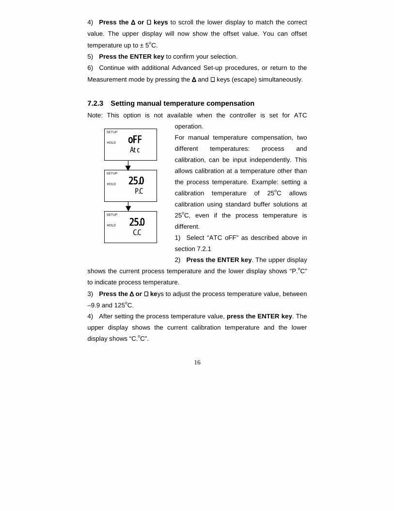
7.2.3 Setting manual temperature compensationNote: This option is not available when the controller is set for ATC
operation.
For manual temperature compensation, two
different temperatures: process and
calibration, can be input independently. This
allows calibration at a temperature other than
the process temperature. Example: setting a
calibration temperature of 25oC allows
calibration using standard buffer solutions at
25oC, even if the process temperature is
different.
1) Select “ATC oFF” as described above in
section 7.2.1
2) Press the ENTER key. The upper display
shows the current process temperature and the lower display shows “P.oC”
to indicate process temperature.
3) Press the ∆∆∆∆ or ∇∇∇∇ keys to adjust the process temperature value, between
–9.9 and 125oC.
4) After setting the process temperature value, press the ENTER key. The
upper display shows the current calibration temperature and the lower
display shows “C.oC”.
25.025.025.025.0C.C
SETUP
HOLD
oFFoFFoFFoFFAtc
SETUP
HOLD
25.025.025.025.0P.C
SETUP
HOLD
17
5) Press the ∆∆∆∆ or ∇∇∇∇ keys to adjust the calibration temperature value,
between –9.9 and 125oC.
6) Press the ENTER key to confirm.
7) Continue with additional Advanced Set-up procedures, or return to
Measurement mode by pressing the ∆∆∆∆ and ∇∇∇∇ keys (escape) simultaneously.
18
7.3 Control Relay A/Control Relay B (SP1/SP2) sub-functionThe SP1 option sets the operating parameters for Relay A; the SP2 option
sets the operating parameters for relay B. Since these groups have the
same set-up parameters, they are described together.
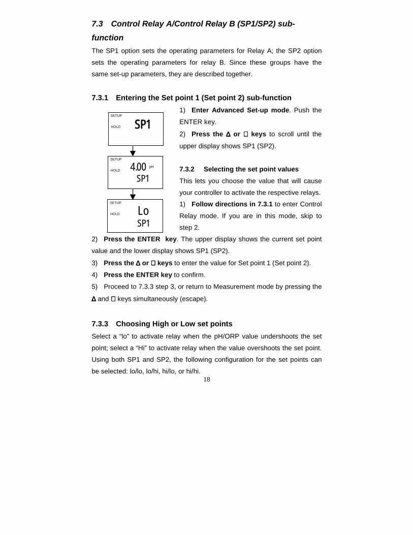
7.3.1 Entering the Set point 1 (Set point 2) sub-function1) Enter Advanced Set-up mode. Push the
ENTER key.
2) Press the ∆∆∆∆ or ∇∇∇∇ keys to scroll until the
upper display shows SP1 (SP2).
7.3.2 Selecting the set point valuesThis lets you choose the value that will cause
your controller to activate the respective relays.
1) Follow directions in 7.3.1 to enter Control
Relay mode. If you are in this mode, skip to
step 2.
2) Press the ENTER key. The upper display shows the current set point
value and the lower display shows SP1 (SP2).
3) Press the ∆∆∆∆ or ∇∇∇∇ keys to enter the value for Set point 1 (Set point 2).
4) Press the ENTER key to confirm.
5) Proceed to 7.3.3 step 3, or return to Measurement mode by pressing the
∆∆∆∆ and ∇∇∇∇ keys simultaneously (escape).
7.3.3 Choosing High or Low set pointsSelect a “lo” to activate relay when the pH/ORP value undershoots the set
point; select a “Hi” to activate relay when the value overshoots the set point.
Using both SP1 and SP2, the following configuration for the set points can
be selected: lo/lo, lo/hi, hi/lo, or hi/hi.
SP1SP1SP1SP1SETUP
HOLD
Lo SP1
SETUP
HOLD
4.00 pH
SP1
SETUP
HOLD
19
1) Follow directions in 7.3.1 to enter Control Relay mode.
2) Press the ENTER key until the upper display shows Lo or Hi and the
lower display shows SP1 (SP2).
3) Press the ∆∆∆∆ or ∇∇∇∇ keys to select low (lo) or high (hi) set point for SP1
(SP2).
4) Press the ENTER key to confirm.
5) Proceed to 7.3.4 step 3, or return Measurement mode by pressing the
∆∆∆∆ and ∇∇∇∇ keys simultaneously (escape).
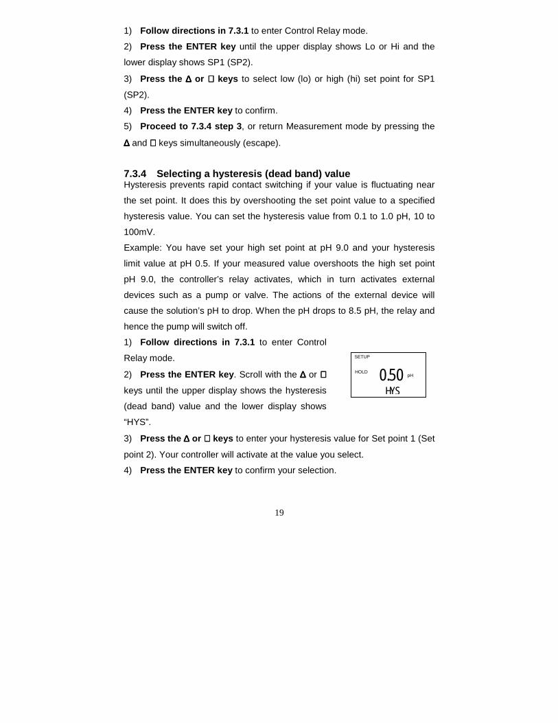
7.3.4 Selecting a hysteresis (dead band) valueHysteresis prevents rapid contact switching if your value is fluctuating near
the set point. It does this by overshooting the set point value to a specified
hysteresis value. You can set the hysteresis value from 0.1 to 1.0 pH, 10 to
100mV.
Example: You have set your high set point at pH 9.0 and your hysteresis
limit value at pH 0.5. If your measured value overshoots the high set point
pH 9.0, the controller’s relay activates, which in turn activates external
devices such as a pump or valve. The actions of the external device will
cause the solution’s pH to drop. When the pH drops to 8.5 pH, the relay and
hence the pump will switch off.
1) Follow directions in 7.3.1 to enter Control
Relay mode.
2) Press the ENTER key. Scroll with the ∆∆∆∆ or ∇∇∇∇keys until the upper display shows the hysteresis
(dead band) value and the lower display shows
“HYS”.
3) Press the ∆∆∆∆ or ∇∇∇∇ keys to enter your hysteresis value for Set point 1 (Set
point 2). Your controller will activate at the value you select.
4) Press the ENTER key to confirm your selection.
0.50 pH
HYS
SETUP
HOLD
20
5) Proceed to 7.3.5 step 3, or return to Measurement mode by pressing
the ∆∆∆∆ and ∇∇∇∇ keys simultaneously (escape).
NOTE: Please refer to Appendix 3 for a graphical representation of the
Hysteresis.
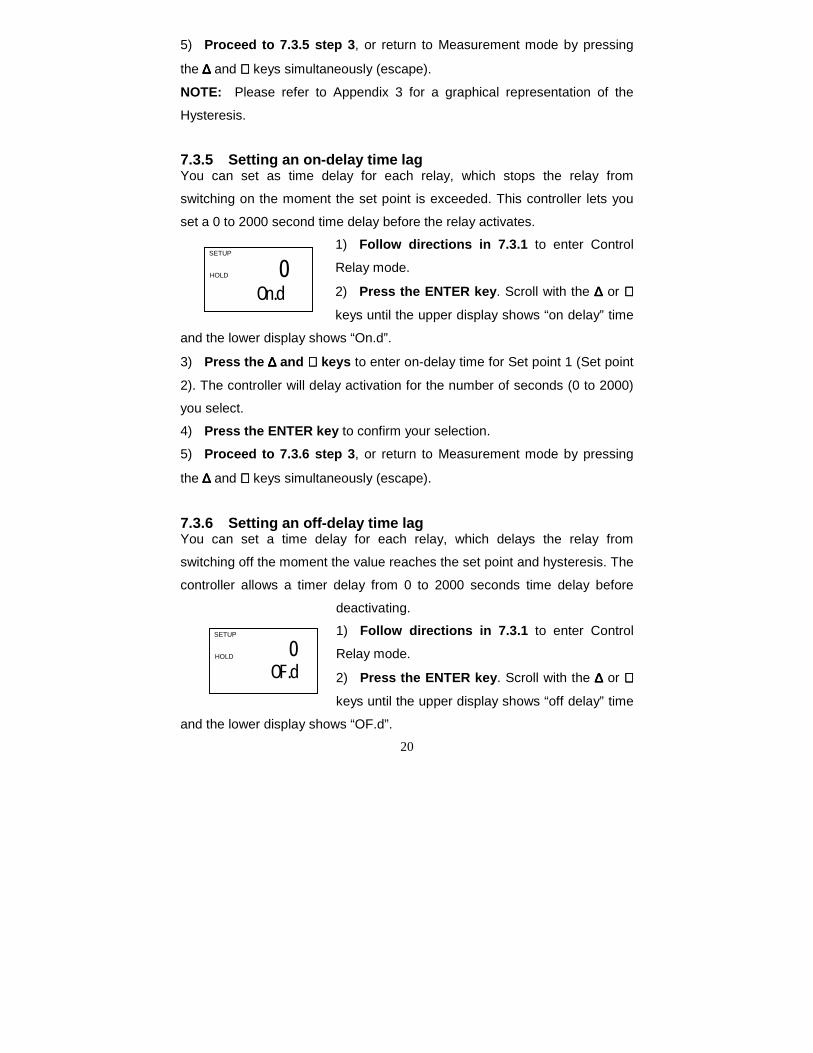
7.3.5 Setting an on-delay time lagYou can set as time delay for each relay, which stops the relay from
switching on the moment the set point is exceeded. This controller lets you
set a 0 to 2000 second time delay before the relay activates.
1) Follow directions in 7.3.1 to enter Control
Relay mode.
2) Press the ENTER key. Scroll with the ∆∆∆∆ or ∇∇∇∇keys until the upper display shows “on delay” time
and the lower display shows “On.d”.
3) Press the ∆∆∆∆ and ∇∇∇∇ keys to enter on-delay time for Set point 1 (Set point
2). The controller will delay activation for the number of seconds (0 to 2000)
you select.
4) Press the ENTER key to confirm your selection.
5) Proceed to 7.3.6 step 3, or return to Measurement mode by pressing
the ∆∆∆∆ and ∇∇∇∇ keys simultaneously (escape).
7.3.6 Setting an off-delay time lagYou can set a time delay for each relay, which delays the relay from
switching off the moment the value reaches the set point and hysteresis. The
controller allows a timer delay from 0 to 2000 seconds time delay before
deactivating.
1) Follow directions in 7.3.1 to enter Control
Relay mode.
2) Press the ENTER key. Scroll with the ∆∆∆∆ or ∇∇∇∇keys until the upper display shows “off delay” time
and the lower display shows “OF.d”.
0 On.d
SETUP
HOLD
0OF.d
SETUP
HOLD

21
3) Press the ∆∆∆∆ or ∇∇∇∇ keys to enter off-delay time for Set point 1 (Set point
2). The controller will delay activation for the number of seconds (0 to 2000)
you select.
4) Press the ENTER key to confirm your selection.
5) Continue with Advanced Set-up mode procedures, or return to
Measurement mode by pressing the ∆∆∆∆ and ∇∇∇∇ keys simultaneously (escape).
22
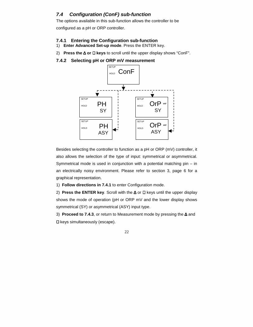
7.4 Configuration (ConF) sub-functionThe options available in this sub-function allows the controller to be
configured as a pH or ORP controller.
7.4.1 Entering the Configuration sub-function1) Enter Advanced Set-up mode. Press the ENTER key.
2) Press the ∆∆∆∆ or ∇∇∇∇ keys to scroll until the upper display shows “ConF”.
7.4.2 Selecting pH or ORP mV measurement
Besides selecting the controller to function as a pH or ORP (mV) controller, it
also allows the selection of the type of input: symmetrical or asymmetrical.
Symmetrical mode is used in conjunction with a potential matching pin – in
an electrically noisy environment. Please refer to section 3, page 6 for a
graphical representation.
1) Follow directions in 7.4.1 to enter Configuration mode.
2) Press the ENTER key. Scroll with the ∆∆∆∆ or ∇∇∇∇ keys until the upper display
shows the mode of operation (pH or ORP mV and the lower display shows
symmetrical (SY) or asymmetrical (ASY) input type.
3) Proceed to 7.4.3, or return to Measurement mode by pressing the ∆∆∆∆ and
∇∇∇∇ keys simultaneously (escape).
SETUP
ConFHOLD
PHSY
SETUP
HOLD
PH ASY
SETUP
HOLD
SETUP
HOLD
OrP mV
SY
SETUP
HOLD
OrP mV
ASY
23
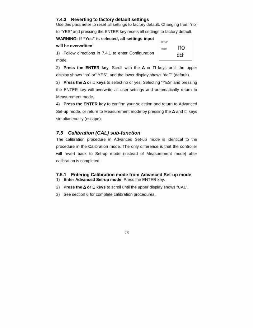
7.4.3 Reverting to factory default settingsUse this parameter to reset all settings to factory default. Changing from “no”
to “YES” and pressing the ENTER key resets all settings to factory default.
WARNING: If “Yes” is selected, all settings inputwill be overwritten!1) Follow directions in 7.4.1 to enter Configuration
mode.
2) Press the ENTER key. Scroll with the ∆∆∆∆ or ∇∇∇∇ keys until the upper
display shows “no” or” YES”, and the lower display shows “deF” (default).
3) Press the ∆∆∆∆ or ∇∇∇∇ keys to select no or yes. Selecting “YES” and pressing
the ENTER key will overwrite all user-settings and automatically return to
Measurement mode.
4) Press the ENTER key to confirm your selection and return to Advanced
Set-up mode, or return to Measurement mode by pressing the ∆∆∆∆ and ∇∇∇∇ keys
simultaneously (escape).
7.5 Calibration (CAL) sub-functionThe calibration procedure in Advanced Set-up mode is identical to the
procedure in the Calibration mode. The only difference is that the controller
will revert back to Set-up mode (instead of Measurement mode) after
calibration is completed.
7.5.1 Entering Calibration mode from Advanced Set-up mode1) Enter Advanced Set-up mode. Press the ENTER key.
2) Press the ∆∆∆∆ or ∇∇∇∇ keys to scroll until the upper display shows “CAL”.
3) See section 6 for complete calibration procedures.
nodEF
SETUP
HOLD
24
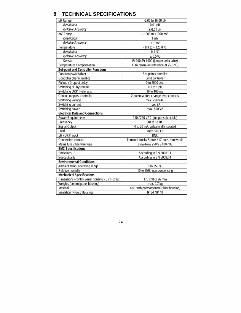
8 TECHNICAL SPECIFICATIONSpH Range -2.00 to 16.00 pH Resolution 0.01 pH Relative Accuracy ± 0.01 pHmV Range - 1000 to +1000 mV Resolution 1 mV Relative Accuracy ± 1 mVTemperature - 9.9 to + 125.0 oC Resolution 0.1 oC Relative Accuracy ± 0.5 oC Sensor Pt 100 /Pt 1000 (jumper selectable)Temperature Compensation Auto / manual (reference at 25.0 oC)Set-point and Controller FunctionsFunction (switchable) Set-point controllerController characteristics Limit controllerPickup / Dropout delay 0 to 2000 sec.Switching pH hysteresis 0.1 to 1 pHSwitching ORP hysteresis 10 to 100 mVContact outputs, controller 2 potential-free change-over contactsSwitching voltage max. 250 VACSwitching current max. 3ASwitching power max. 600 VAElectrical Data and ConnectionsPower Requirements 110 / 220 VAC (jumper selectable)Frequency 48 to 62 HzSignal Output 4 to 20 mA, galvanically isolatedLoad max. 500 ΩpH / ORP input BNCConnection terminal Terminal blocks 5-pole / 17-pole, removableMains fuse / fine wire fuse slow-blow 250 V / 100 mAEMC SpecificationsEmissions According to EN 50081-1Susceptibility According to EN 50082-1Environmental ConditionsAmbient temp. operating range 0 to +50 oCRelative humidity 10 to 95%, non-condensingMechanical SpecificationsDimensions (control panel housing - L x H x W) 175 x 96 x 96 mmWeights (control panel housing) max. 0.7 kgMaterial ABS with polycarbonate (front housing)Insulation (Front / Housing) IP 54 / IP 40
25
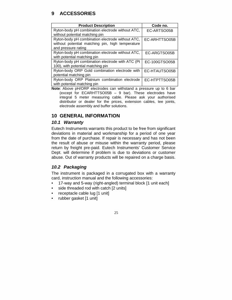
9 ACCESSORIES
Product Description Code no.Ryton-body pH combination electrode without ATC,without potential matching pin
EC-ARTSO05B
Ryton-body pH combination electrode without ATC,without potential matching pin, high temperatureand pressure rating
EC-ARHTTSO05B
Ryton-body pH combination electrode without ATC,with potential matching pin
EC-ARGTSO05B
Ryton-body pH combination electrode with ATC (Pt100), with potential matching pin
EC-100GTSO05B
Ryton-body ORP Gold combination electrode withpotential matching pin
EC-HTAUTSO05B
Ryton-body ORP Platnium combination electrodewith potential matching pin
EC-HTPTTSO05B
Note: Above pH/ORP electrodes can withstand a pressure up to 6 bar(except for ECARHTTSO05B – 9 bar). These electrodes haveintegral 5 meter measuring cable. Please ask your authoriseddistributor or dealer for the prices, extension cables, tee joints,electrode assembly and buffer solutions.
10 GENERAL INFORMATION10.1 WarrantyEutech Instruments warrants this product to be free from significantdeviations in material and workmanship for a period of one yearfrom the date of purchase. If repair is necessary and has not beenthe result of abuse or misuse within the warranty period, pleasereturn by freight pre-paid. Eutech Instruments’ Customer ServiceDept. will determine if problem is due to deviations or customerabuse. Out of warranty products will be repaired on a charge basis.
10.2 PackagingThe instrument is packaged in a corrugated box with a warrantycard, instruction manual and the following accessories:• 17-way and 5-way (right-angled) terminal block [1 unit each]• side threaded rod with catch [2 units]• receptacle cable lug [1 unit]• rubber gasket [1 unit]
26
10.3 Return of GoodsAuthorisation must be obtained from Eutech Instruments’Customer Service Dept. to issue a RGA (Return of GoodsAuthorisation) number before returning items for any reason. Whenapplying for authorisation, please include data requiring the reasonof return. Items must be carefully packed to prevent damage inshipment and insured against possible damage or loss. EutechInstruments will not be responsible for any damage resulting fromcareless or insufficient packing.
Warning: Shipping damage as a result of inadequate packaging isthe user/distributor’s responsibility, whoever applicable.Please follow the guidelines below before shipment.
10.4 Guidelines for Returning Unit for RepairUse the original packaging material, if possible when shipping the unitfor repair. Otherwise wrap it with bubble pack and use a corrugatedbox for better protection. Include a brief description of any faultssuspected for the convenience of Customer Service Dept., if possible.
27
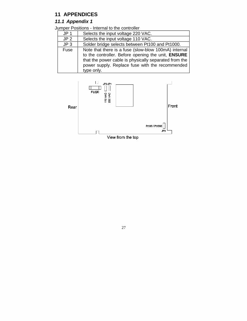
11 APPENDICES11.1 Appendix 1Jumper Positions - Internal to the controller
JP 1 Selects the input voltage 220 VAC.JP 2 Selects the input voltage 110 VAC.JP 3 Solder bridge selects between Pt100 and Pt1000.Fuse Note that there is a fuse (slow-blow 100mA) internal
to the controller. Before opening the unit, ENSUREthat the power cable is physically separated from thepower supply. Replace fuse with the recommendedtype only.
28
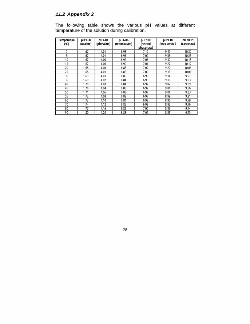
11.2 Appendix 2
The following table shows the various pH values at differenttemperature of the solution during calibration.
Temperature(oC)
pH 1.68(oxalate)
pH 4.01(phthalate)
pH 6.86(tetraoxalate)
pH 7.00(neutral
phosphate)
pH 9.18(tetra borate )
pH 10.01(carbonate)
0 1.67 4.01 6.98 7.12 9.47 10.325 1.67 4.01 6.95 7.09 9.38 10.2510 1.67 4.00 6.92 7.06 9.32 10.1815 1.67 4.00 6.90 7.04 9.27 10.1220 1.68 4.00 6.88 7.02 9.22 10.0625 1.68 4.01 6.86 7.00 9.18 10.0130 1.69 4.01 6.85 6.99 9.14 9.9735 1.69 4.02 6.84 6.98 9.10 9.9340 1.70 4.03 6.84 6.97 9.07 9.8945 1.70 4.04 6.83 6.97 9.04 9.8650 1.71 4.06 6.83 6.97 9.01 9.8355 1.72 4.08 6.83 6.97 8.99 9.8160 1.73 4.10 6.84 6.98 8.96 9.7970 1.74 4.12 6.85 6.99 8.92 9.7680 1.77 4.16 6.86 7.00 8.89 9.7490 1.80 4.20 6.88 7.02 8.85 9.73
29
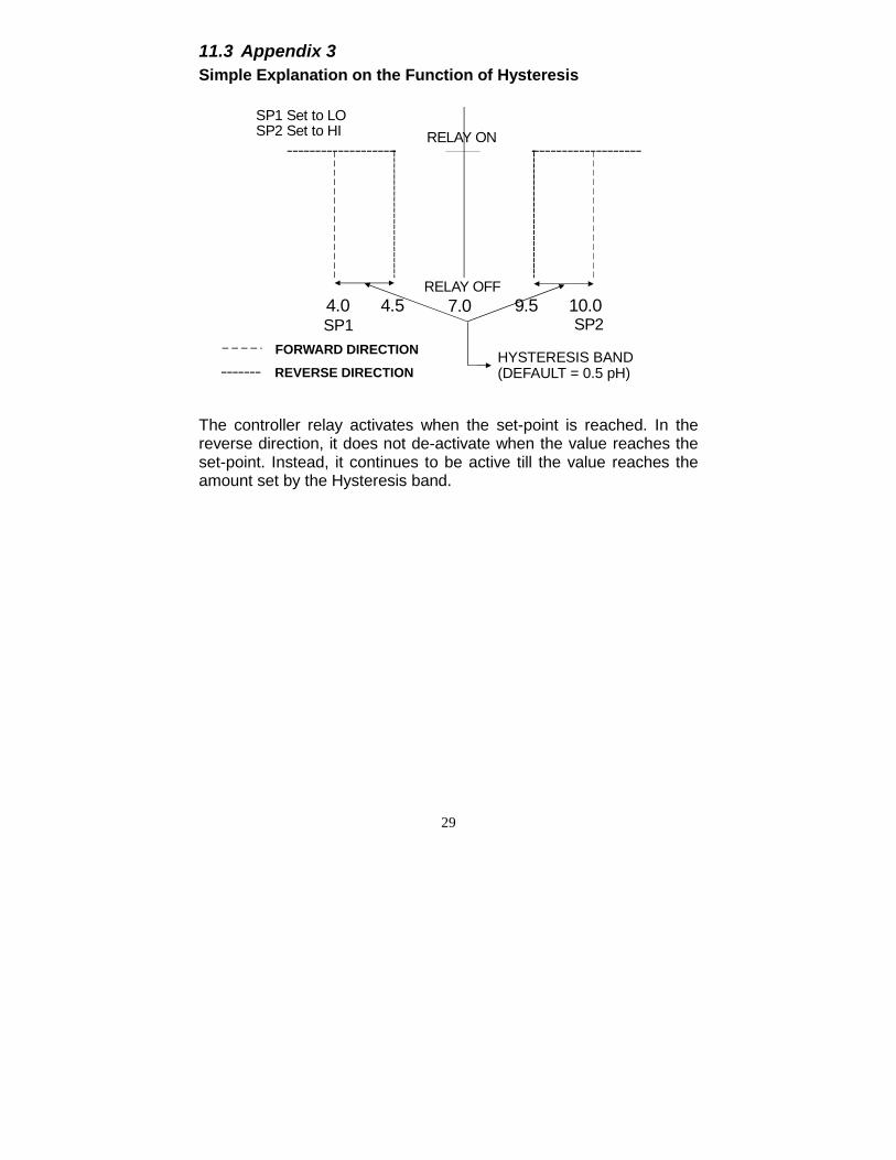
11.3 Appendix 3Simple Explanation on the Function of Hysteresis
The controller relay activates when the set-point is reached. In thereverse direction, it does not de-activate when the value reaches theset-point. Instead, it continues to be active till the value reaches theamount set by the Hysteresis band.
4.0 4.5 9.5 10.07.0RELAY OFF
HYSTERESIS BAND(DEFAULT = 0.5 pH)
FORWARD DIRECTIONREVERSE DIRECTION
SP1 SP2
RELAY ONSP1 Set to LOSP2 Set to HI
CALIBRATION RECORD
Calibration Date Electrode Slope Electrode Offset