piMFC PFC-80 data sheet - MKS Instruments, Inc
8
MFC MODEL PFC-80 π WWW.MKSINST.COM Flow Solutions DISCONTINUED
Transcript of piMFC PFC-80 data sheet - MKS Instruments, Inc
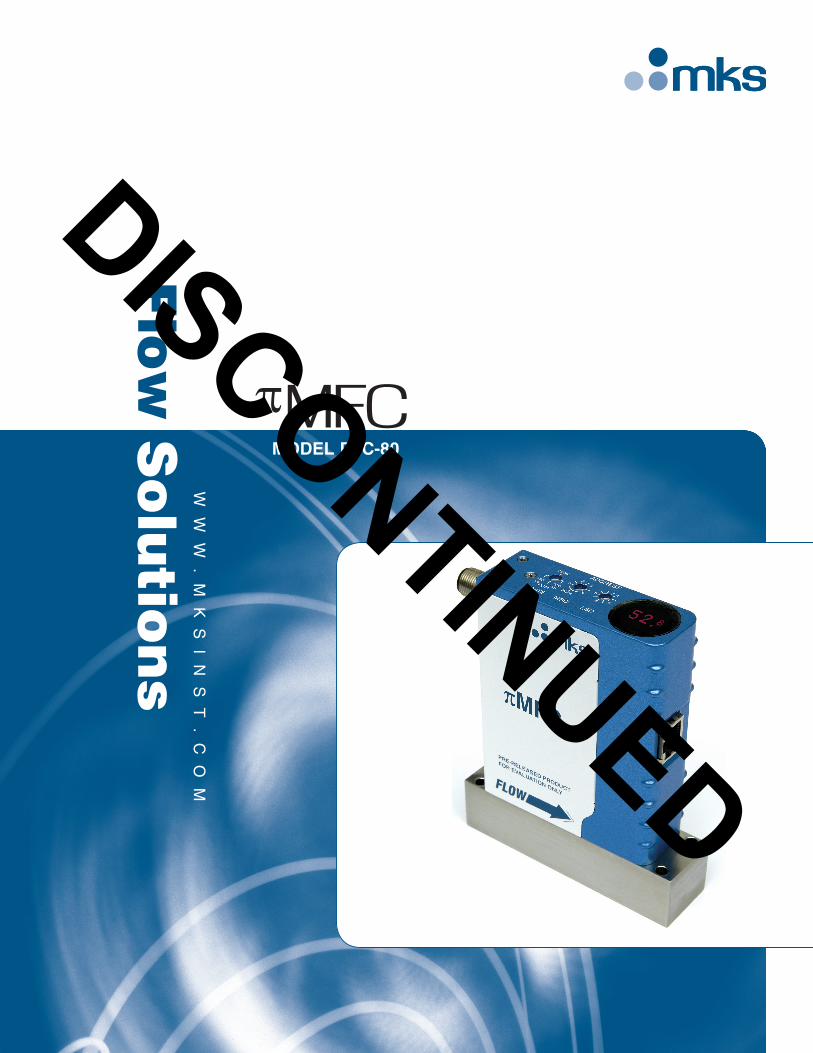
MFCMODEL PFC-80
π
WW
W.
MK
SI
NS
T.
CO
M
Flo
w S
olu
tion
s
DISCONTINUED
The next generation MKS πMFC (mass flow controller) includes technology improvements in functionality and performance to help users in semiconductor and high purity thin-film applications increase tool throughput and reduce overall system costs. Real-time accurate flow control that is insensitive to upstream and downstream pressure disturbances is provided through advanced digital algorithms. Enabling real-time control of process gas flow, accuracy and repeatability is significantly improved over conventional PID based digital MFCs, resulting in better chamber matching.
Cost savings to users are seen through several innovative enhancements. To reduce the number of MFCs in inventory, users can access specific MFC gas calibrations and flow ranges from up to 31 stored gas tables, configuring the πMFC right off the shelf. The integrated pressure sensor and local LED display help to reduce the number of components required in a gas stick. A web based browser interface allows for setup and troubleshooting of MFCs in-situ, thereby reducing the number of “No Problem Found” MFC replacements and the need to break the process gas line.
The πMFC represents MKS’ ongoing dedication to helping customers increase productivity while reducing system costs.
DescriptionFeatures & BenefitsIncreases Throughput and Performance• Insensitive to upstream and downstream pressure disturbances
— Accurate flow control without the need for additional dedicated line pressure regulators
• Enables better chamber matching through increased MFC accuracy of any process gas
• Increases tool uptime through reduction of “No Problem Found” MFC replacements
—Includes embedded diagnostics software that allows users to check MFC functionality without removing the MFC
—E-diagnostics through embedded Ethernet interface
Reduces Overall Costs• Reduces MFC inventory through multi-gas, multi- range availability
• Enables reduction in number of gas stick components needed, such as pressure regulators, filters, and pressure transducers
• Minimizes overall footprint of gas delivery module
Easy to Integrate and Operate• Straightforward configuration and diagnostics through Ethernet interface
— Uses standard web browser – no special software required
—Includes remote PC application
• Easy viewing of line pressure, flow rate, gas type, full scale flow range and Ethernet address with bright LED display
DISCONTINUED
Description (cont’d)
As a technology leader in MFCs, the πMFC represents the latest in cost effective technology and innovation to meet production needs.
The performance of the πMFC is quickly apparent where short process steps are required. The ability to provide accurate and real-time control of high molecular weight gas applications differentiates πMFC from other market brands. This results in precise etch rates and controlled deposition for most critical semiconductor processes.
To enable ease of integration into next generation or existing process tools, a variety of mechanical configurations exist, including surface mount and VCR®. Coupled with its compact size, the πMFC provides an ideal way to migrate from existing analog MFCs where reducing MFC inventory and improving process repeatability are important.
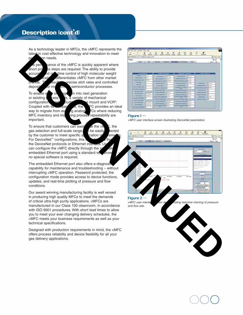
To ensure that customers can easily use the πMFC, the gas selection and full-scale range can be easily selected by the customer to meet specific application requirements. For DeviceNet™ configurations, this is performed through the DeviceNet protocols or Ethernet interface. Users can configure the πMFC directly through the separate embedded Ethernet port using a standard web browser – no special software is required.
The embedded Ethernet port also offers e-diagnostics capability for maintenance and troubleshooting – without interrupting πMFC operation. Password protected, the configuration mode provides access to device functions, updates, and real-time plotting of pressure and flow conditions.
Our award winning manufacturing facility is well versed in producing high quality MFCs to meet the demands of critical ultra-high purity applications. πMFCs are manufactured in our Class 100 cleanroom, in accordance with ISO 9001 procedures. With short lead times to allow you to meet your ever changing delivery schedules, the πMFC meets your business requirements as well as your technical specifications.
Designed with production requirements in mind, the πMFC offers process reliability and device flexibility for all your gas delivery applications.
Figure 1 —πMFC user interface screen illustrating DeviceNet parameters
Figure 2 —πMFC user interface screen demonstrating real-time charting of pressure and flow rate.
DISCONTINUED
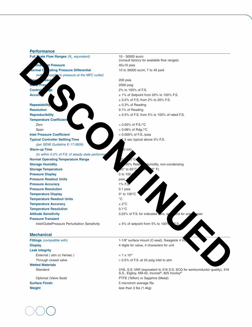
PerformanceFull Scale Flow Ranges (N2 equivalent) 10 - 30000 sccm (consult factory for available flow ranges)
Optimal Inlet Pressure 40±10 psia
Normal Operating Pressure Differential 10 to 30000 sccm; 7 to 45 psid
(with atmospheric pressure at the MFC outlet)
Proof Pressure 200 psia
Burst Pressure 2000 psig
Control Range 2% to 100% of F.S.
Accuracy ± 1% of Setpoint from 20% to 100% F.S.
± 0.2% of F.S. from 2% to 20% F.S.
Repeatability ± 0.3% of Reading
Resolution 0.1% of Reading
Reproducibility ± 0.5% of F.S. from 5% to 100% of rated F.S.
Temperature Coefficients
Zero < 0.05% of F.S./°C
Span < 0.08% of Rdg./°C
Inlet Pressure Coefficient < 0.005% of F.S../psia
Typical Controller Settling Time < 1.5 sec typical above 5% F.S.
(per SEMI Guideline E-17-0600)
Warm-up Time < 30 min
(to within 0.2% of F.S. of steady state performance)
Normal Operating Temperature Range 10° to 50°C
Storage Humidity 0 to 95% Relative Humidity, non-condensing
Storage Temperature -20° to 65°C (-4° to 149° F)
Pressure Display 0 to 100 psia
Pressure Readout Units psia, kPA
Pressure Accuracy 1% F.S.
Pressure Resolution 0.1 psia
Temperature Display 0° to 100°C
Temperature Readout Units °C
Temperature Accuracy ± 2°C
Temperature Resolution 0.1°C
Attitude Sensitivity 0.25% of F.S. for indicated zero, span and for actual span
Pressure Transient
Inlet/OutletPressure Perturbation Sensitivity ± 5% of setpoint from 5% to 100% of F.S.
MechanicalFittings (compatible with) 1-1/8” surface mount (C-seal), Swagelok 4 VCR
Display 4 digits for value, 4 characters for unit
Leak Integrity
External ( atm cc He/sec ) < 1 x 10⁻⁹
Through closed valve ≤ 0.5% of F.S. at 25 psig inlet to atmWetted Materials Standard 316L S.S. VAR (equivalent to 316 S.S. SCQ for semiconductor quality), 316 S.S., Elgiloy, KM-45, Inconel®, 825 Incoloy®
Optional (Valve Seat) PTFE (Teflon) or Sapphire (Metal)
Surface Finish 5 microinch average Ra
Weight less than 3 lbs (1.4kg)
DISCONTINUED
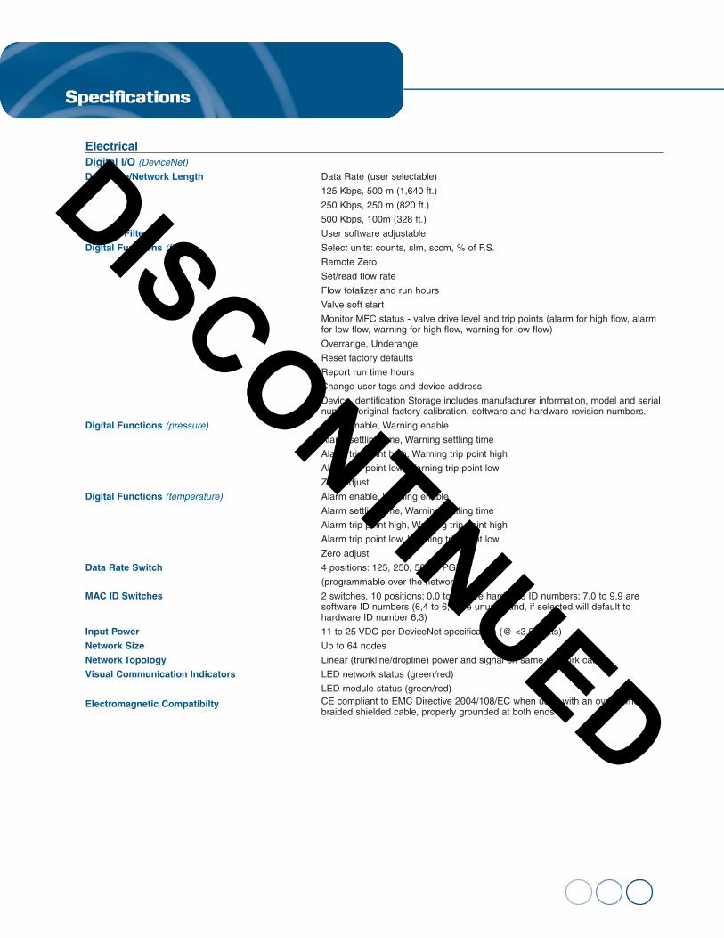
Specifications
Electrical Digital I/O (DeviceNet)
Data Rate/Network Length Data Rate (user selectable)
125 Kbps, 500 m (1,640 ft.)
250 Kbps, 250 m (820 ft.)
500 Kbps, 100m (328 ft.)
Level of Filtering User software adjustable
Digital Functions (flow) Select units: counts, slm, sccm, % of F.S.
Remote Zero
Set/read flow rate
Flow totalizer and run hours
Valve soft start
Monitor MFC status - valve drive level and trip points (alarm for high flow, alarm for low flow, warning for high flow, warning for low flow)
Overrange, Underange
Reset factory defaults
Report run time hours
Change user tags and device address
Device Identification Storage includes manufacturer information, model and serial number, original factory calibration, software and hardware revision numbers.
Digital Functions (pressure) Alarm enable, Warning enable
Alarm settling time, Warning settling time
Alarm trip point high, Warning trip point high
Alarm trip point low, Warning trip point low
Zero adjust
Digital Functions (temperature) Alarm enable, Warning enable
Alarm settling time, Warning settling time
Alarm trip point high, Warning trip point high
Alarm trip point low, Warning trip point low
Zero adjust
Data Rate Switch 4 positions: 125, 250, 500K, PGM
(programmable over the network)
MAC ID Switches 2 switches, 10 positions; 0,0 to 6,3 are hardware ID numbers; 7,0 to 9,9 are software ID numbers (6,4 to 6,9 are unused and, if selected will default to hardware ID number 6,3)
Input Power 11 to 25 VDC per DeviceNet specification (@ <3.5 watts)
Network Size Up to 64 nodes
Network Topology Linear (trunkline/dropline) power and signal on same network cable
Visual Communication Indicators LED network status (green/red)
LED module status (green/red)
Electromagnetic Compatibilty CE compliant to EMC Directive 2004/108/EC when used with an overall metal braided shielded cable, properly grounded at both ends
DISCONTINUED
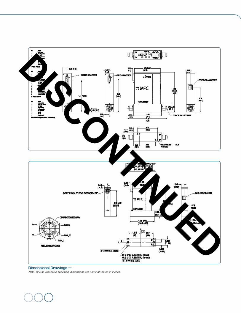
Dimensional Drawings — Note: Unless otherwise specified, dimensions are nominal values in inches.
DISCONTINUED
0
C
013
Ordering Information
M
23
502
P8A
6
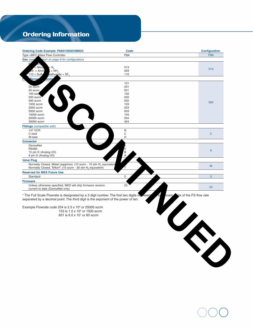
Ordering Code Example: P8A013502C6M023 Code ConfigurationType πMFC Mass Flow Controller P8A
Gas (see gas chart on page 8 for configuration)
For example: 013 = Nitrogen = N2 013 029 = Ammonia = NH3 029 110 = Sulfur Hexafluoride = SF6 110
Flow Range Full Scale* 10 sccm 101 20 sccm 201 50 sccm 501 100 sccm 102 200 sccm 202 500 sccm 502 1000 sccm 103 2000 sccm 203 5000 sccm 503 10000 sccm 104 20000 sccm 204 30000 sccm 304
Fittings (compatible with) 1/4” VCR R C-seal C W-seal H
Connector DeviceNet 6 RS485 5 15 pin D (Analog I/O) B 9 pin D (Analog I/O) A
Valve Plug Normally Closed, Metal (sapphire): (10 sccm - 10 slm N2 equivalent) M Normally Closed, Teflon®: (10 sccm - 30 slm N2 equivalent) T
Reserved for MKS Future Use Standard 0
Firmware Unless otherwise specified, MKS will ship firmware revision 23 current to date (DeviceNet only)
* The Full Scale Flowrate is designated by a 3 digit number. The first two digits represent the significant digits of the FS flow rate separated by a decimal point. The third digit is the exponent of the power of ten.
Example Flowrate code 254 is 2.5 x 10⁴ or 25000 sccm 153 is 1.5 x 10³ or 1500 sccm 601 is 6.0 x 101 or 60 sccm
DISCONTINUED
piMFC_80 - 11/15 © 2005 MKS Instruments, Inc. All rights reserved.
MKS products provided subject to the US Export Regulations. Diversion or transfer contrary to US law is prohibited.
Specifications are subject to change without notice. mksinst™ is a trademark of MKS Instruments, Inc., Andover, MA. Swagelok® and VCR® are registered trademarks of Swagelok Marketing Co., Solon, OH. Inconel® and Incoloy® are registered trademarks of Inco Alloys, Huntington, WV. Teflon® is a registered trademark of E.I. Dupont, Wilmington, DE. DeviceNet™ is a trademark of the Open DeviceNet Vendor Association, Coral Springs, FL.
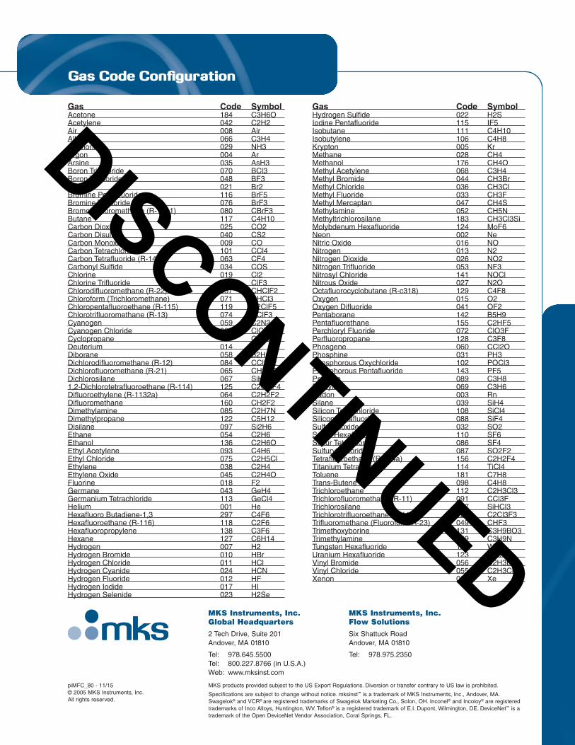
Gas Code Configuration
Gas Code SymbolAcetone 184 C3H6OAcetylene 042 C2H2Air 008 AirAllene 066 C3H4Ammonia 029 NH3Argon 004 ArArsine 035 AsH3Boron Trichloride 070 BCl3Boron Trifluoride 048 BF3Bromine 021 Br2Bromine Pentafluoride 116 BrF5Bromine Trifluoride 076 BrF3Bromotrifluoromethane (R-13b1) 080 CBrF3Butane 117 C4H10Carbon Dioxide 025 CO2Carbon Disulfide 040 CS2Carbon Monoxide 009 COCarbon Tetrachloride 101 CCl4Carbon Tetrafluoride (R-14) 063 CF4Carbonyl Sulfide 034 COSChlorine 019 Cl2Chlorine Trifluoride 077 ClF3Chlorodifluoromethane (R-22) 057 CHClF2Chloroform (Trichloromethane) 071 CHCl3Chloropentafluoroethane (R-115) 119 C2ClF5Chlorotrifluoromethane (R-13) 074 CClF3Cyanogen 059 C2N2Cyanogen Chloride 037 ClCNCyclopropane 061 C3H6Deuterium 014 D2Diborane 058 B2H6Dichlorodifluoromethane (R-12) 084 CCl2F2Dichlorofluoromethane (R-21) 065 CHCl2FDichlorosilane 067 SiH2Cl21,2-Dichlorotetrafluoroethane (R-114) 125 C2Cl2F4Difluoroethylene (R-1132a) 064 C2H2F2Difluoromethane 160 CH2F2Dimethylamine 085 C2H7NDimethylpropane 122 C5H12Disilane 097 Si2H6Ethane 054 C2H6Ethanol 136 C2H6OEthyl Acetylene 093 C4H6Ethyl Chloride 075 C2H5ClEthylene 038 C2H4Ethylene Oxide 045 C2H4OFluorine 018 F2Germane 043 GeH4Germanium Tetrachloride 113 GeCl4Helium 001 HeHexafluoro Butadiene-1,3 297 C4F6Hexafluoroethane (R-116) 118 C2F6Hexafluoropropylene 138 C3F6Hexane 127 C6H14Hydrogen 007 H2Hydrogen Bromide 010 HBrHydrogen Chloride 011 HClHydrogen Cyanide 024 HCNHydrogen Fluoride 012 HFHydrogen Iodide 017 HIHydrogen Selenide 023 H2Se
Gas Code SymbolHydrogen Sulfide 022 H2SIodine Pentafluoride 115 IF5Isobutane 111 C4H10Isobutylene 106 C4H8Krypton 005 KrMethane 028 CH4Methanol 176 CH4OMethyl Acetylene 068 C3H4Methyl Bromide 044 CH3BrMethyl Chloride 036 CH3ClMethyl Fluoride 033 CH3FMethyl Mercaptan 047 CH4SMethylamine 052 CH5NMethyltrichlorosilane 183 CH3Cl3SiMolybdenum Hexafluoride 124 MoF6Neon 002 NeNitric Oxide 016 NONitrogen 013 N2Nitrogen Dioxide 026 NO2Nitrogen Trifluoride 053 NF3Nitrosyl Chloride 141 NOClNitrous Oxide 027 N2OOctafluorocyclobutane (R-c318) 129 C4F8Oxygen 015 O2Oxygen Difluoride 041 OF2Pentaborane 142 B5H9Pentafluorethane 155 C2HF5Perchloryl Fluoride 072 ClO3FPerfluoropropane 128 C3F8Phosgene 060 CCl2OPhosphine 031 PH3Phosphorous Oxychloride 102 POCl3Phosphorous Pentafluoride 143 PF5Propane 089 C3H8Propylene 069 C3H6Radon 003 RnSilane 039 SiH4Silicon Tetrachloride 108 SiCl4Silicon Tetrafluoride 088 SiF4Sulfur Dioxide 032 SO2Sulfur Hexafluoride 110 SF6Sulfur Tetrafluoride 086 SF4Sulfuryl Fluoride 087 SO2F2Tetrafluoroethane (R-134a) 156 C2H2F4Titanium Tetrachloride 114 TiCl4Toluene 181 C7H8Trans-Butene 098 C4H8Trichloroethane 112 C2H3Cl3Trichlorofluoromethane (R-11) 091 CCl3FTrichlorosilane 147 SiHCl3Trichlorotrifluoroethane (R-113) 126 C2Cl3F3Trifluoromethane (Fluoroform R-23) 049 CHF3Trimethoxyborine 131 C3H9BO3Trimethylamine 109 C3H9NTungsten Hexafluoride 121 WF6Uranium Hexafluoride 123 UF6Vinyl Bromide 056 C2H3BrVinyl Chloride 055 C2H3ClXenon 006 Xe
MKS Instruments, Inc.Global Headquarters 2 Tech Drive, Suite 201 Andover, MA 01810
Tel: 978.645.5500 Tel: 800.227.8766 (in U.S.A.) Web: www.mksinst.com
MKS Instruments, Inc.Flow Solutions Six Shattuck Road Andover, MA 01810
Tel: 978.975.2350
DISCONTINUED