ED2 - sankyo-seisakusho.co.jp...ED2.8 Dimensions Figure ED2.8-1 (Unit : mm) ※1(24)M5×0.8,...
16
※1:Mounting holes on sides R, S, V, and W are standard. Mounting holes on only a user-specified side is optional. ED2.8 Dimensions Figure ED2.8-1 (Unit : mm) ※1(24)M5×0.8, 10DP Stop Position Indexing period origin(0°) S T U R V c d b a S V W R T INPUT OUTPUT 6 44 56 27 27 110 25 25 20 20 80 68 6 44 6 φ12 φ8 28 96 40 56 28 38 33 φ15 (0.5) (0.5) φ10 φ8 26 26 28 φ10 0 -0.015 5 0 -0.015 0 -0.015 0 -0.015 ED2.8
Transcript of ED2 - sankyo-seisakusho.co.jp...ED2.8 Dimensions Figure ED2.8-1 (Unit : mm) ※1(24)M5×0.8,...
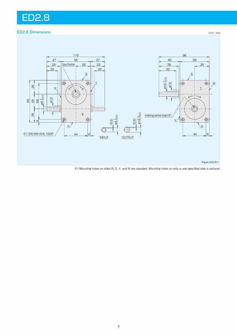
※1:Mounting holes on sides R, S, V, and W are standard. Mounting holes on only a user-specified side is optional.
ED2.8 Dimensions
Figure ED2.8-1
(Unit : mm)
※1(24)M5×0.8, 10DP
Stop Position
Indexing period origin(0°)
S
TU
R
V
c d
b a
S
V
W
R
T
INPUT OUTPUT644
5627 27110
25 252020
80 686
44 6
φ12
φ8
28
9640 56
283833
φ15
(0.5)
(0.5)
φ10
φ8
2626
28
φ10
0 -0.015
5
0 -0.015
0 -0.015
0 -0.015
ED2.8
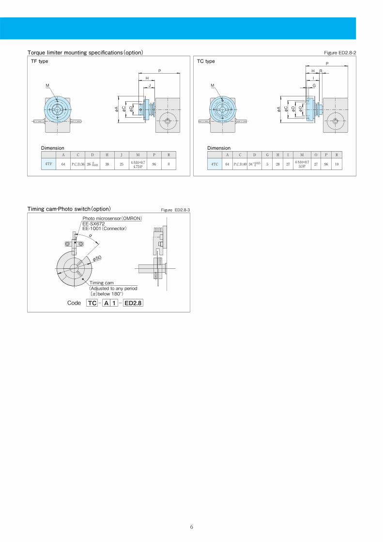
Timing cam‐Photo switch(option)
Code TC A 1 ED2.8
Figure ED2.8-3
φ50
Photo microsensor(OMRON)EE-SX672EE-1001(Connector)
Timing cam(Adjusted to any period 〔α〕below 180°)
α
Torque limiter mounting specifications(option)TF type TC type
A C D H J M P R
64 P.C.D.36 26 38 25 4-M4×0.74.7DP 96 04TF
Dimension Dimension
M
φD
φA
J
H
P
φC
M G
φC
φA
φD
I
H R
P
φO
Figure ED2.8-2
6
0-0.021
A C D G H M P R
64 P.C.D.40 34 5 28 4-M4×0.75DP 96 10
O
27
I
274TC +0.025 0
7
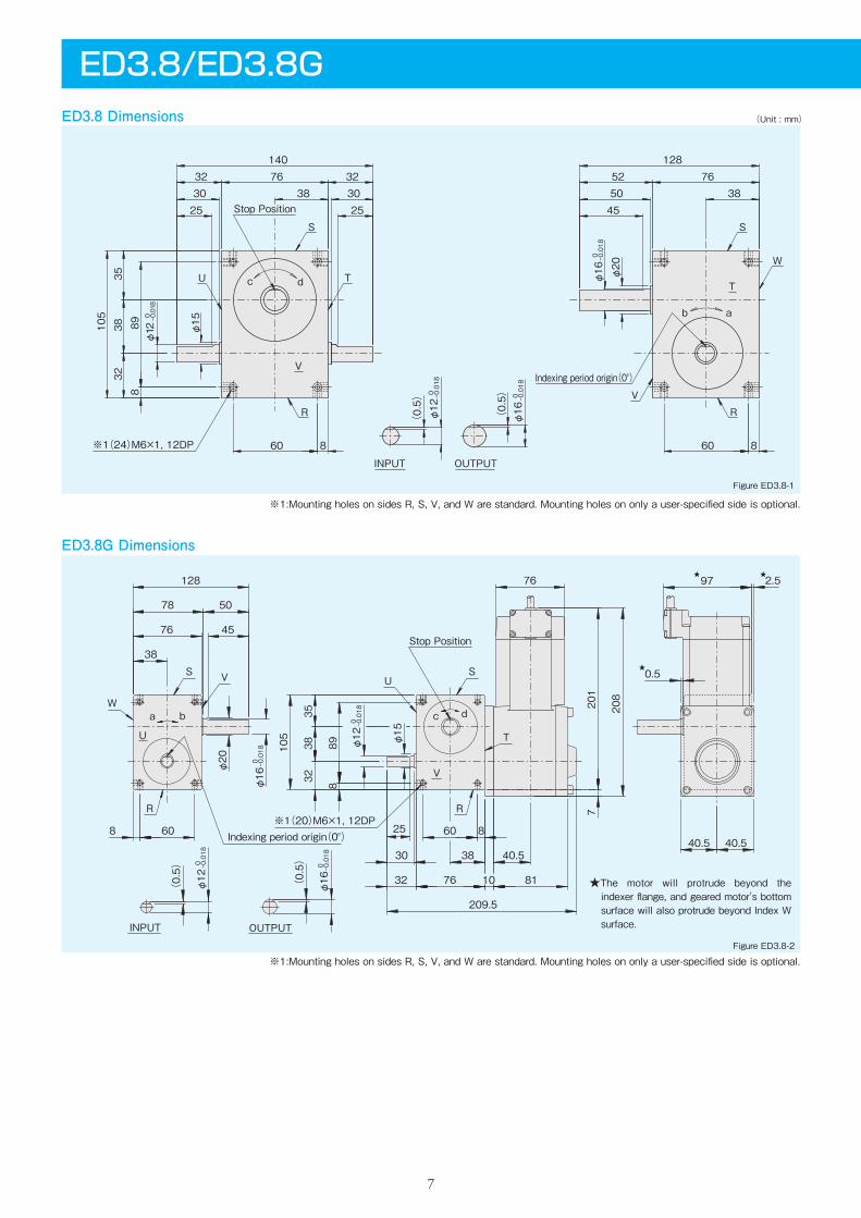
ED3.8/ED3.8GED3.8 Dimensions
ED3.8G Dimensions
(Unit : mm)
※1:Mounting holes on sides R, S, V, and W are standard. Mounting holes on only a user-specified side is optional.
Figure ED3.8-1
Figure ED3.8-2
OUTPUTINPUT
Stop Position
※1(20)M6×1, 12DPIndexing period origin(0°)
R
W
S V
U
US
R
V
T
c da b
76
209.5
40.53830
25
201
φ16
0 -0.018
(0.5)
φ12
0 -0.018
(0.5)
105
208
38
76
78 50
128
45
φ12
0 -0.018
φ15
φ16
0 -0.018
φ20
0.5
7
32 811076
3235
38
889
8 60 860
2.597
40.540.5
★
★
★
※1(24)M6×1, 12DP
Stop Position
S
TU
R
VIndexing period origin(0°)
S
W
VR
Tc d
ab
INPUT OUTPUT
76140
323230 30
2525
898
105
60 8
φ15
φ12
0 -0.018
38
1287652
385045
60 8
φ20
(0.5)
φ12
0 -0.018
φ16
0 -0.018
(0.5)
3532
38
φ16
0 -0.018
※1:Mounting holes on sides R, S, V, and W are standard. Mounting holes on only a user-specified side is optional.
★The motor will protrude beyond the indexer flange, and geared motor's bottom surface will also protrude beyond Index W surface.
8
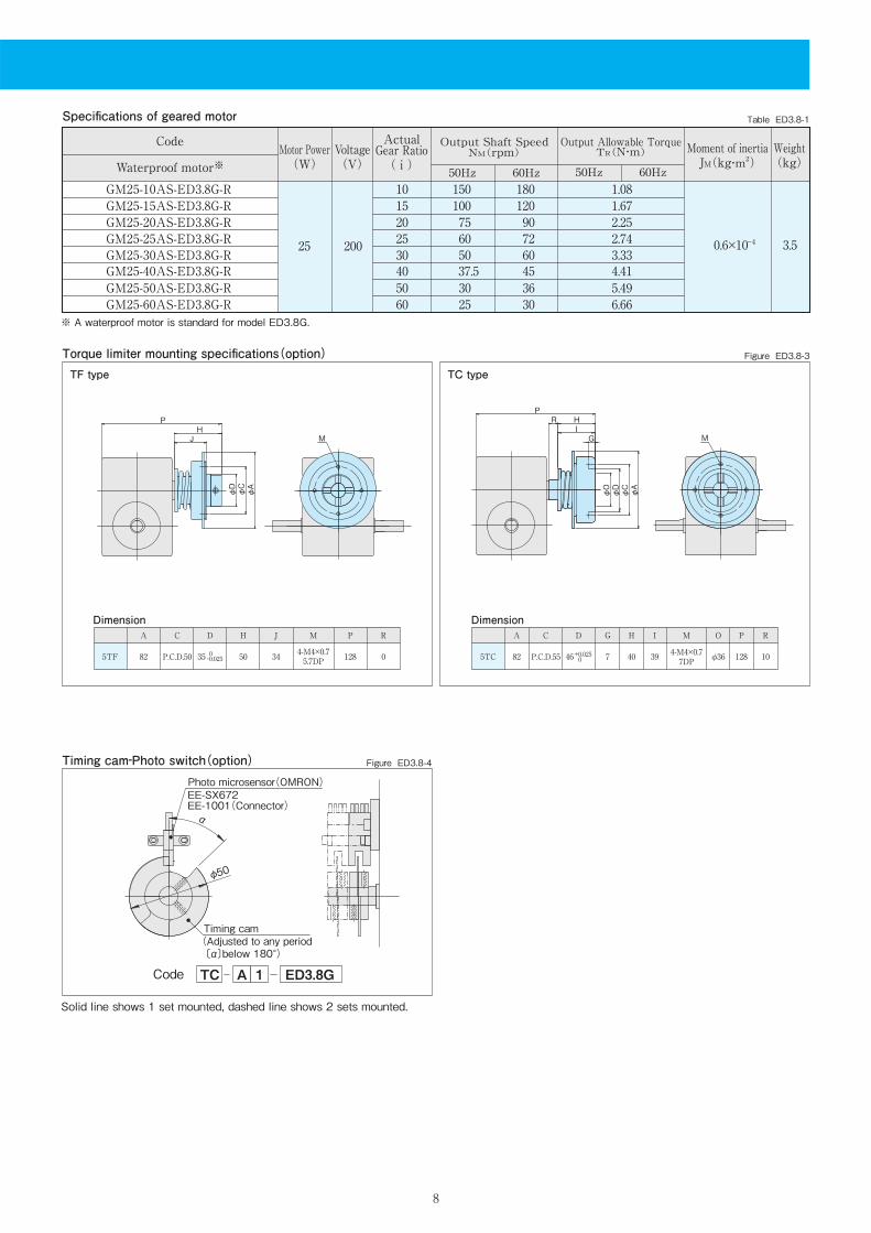
Specifications of geared motor Table ED3.8-1
Figure ED3.8-3
Code
Waterproof motor※Voltage(V)
Motor Power(W)
ActualGear Ratio( i )
Output Shaft SpeedNM(rpm)
50Hz 60Hz
Weight(kg)
Output Allowable TorqueTR(N・m)
50Hz 60Hz
20025 0.6×10⁻⁴ 3.5
2025304050
75 605037.530
90 72 60 45 36
2.252.743.334.415.49
15 100 120 1.6710 150 180 1.08
Moment of inertiaJM(kg・m2)
GM25-20AS-ED3.8G-RGM25-25AS-ED3.8G-RGM25-30AS-ED3.8G-RGM25-40AS-ED3.8G-RGM25-50AS-ED3.8G-R
GM25-15AS-ED3.8G-RGM25-10AS-ED3.8G-R
GM25-60AS-ED3.8G-R 60 25 30 6.66
Torque limiter mounting specifications(option)
Timing cam‐Photo switch(option)
Code TC A 1 ED3.8G
Figure ED3.8-4
50φ
α
Photo microsensor(OMRON)EE-SX672EE-1001(Connector)
Timing cam(Adjusted to any period 〔α〕below 180°)
Solid line shows 1 set mounted, dashed line shows 2 sets mounted.
※ A waterproof motor is standard for model ED3.8G.
TF type TC type
A C D H J M P R
82 P.C.D.50 35 50 34 4-M4×0.75.7DP 128 05TF
DimensionA C D G H M P R
82 P.C.D.55 46 7 40 4-M4×0.77DP 128 10
O
φ36
I
395TC
Dimension
0-0.025
+0.025 0
φAφCφD
JH
P
M G
φAφCφDφO
IR H
P
M
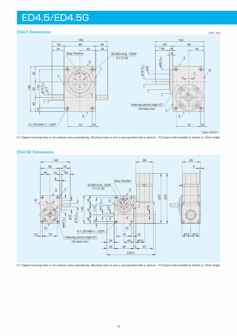
ED4.5G Dimensions
Figure ED4.5-1
Figure ED4.5-2
9
ED4.5/ED4.5GED4.5 Dimensions (Unit : mm)
※1:Tapped mounting holes on all surfaces come automatically. Mounting holes on only a user-specified side is optional. ※2:Output shaft available to shorten to 10mm height.
※1:Tapped mounting holes on all surfaces come automatically. Mounting holes on only a user-specified side is optional. ※2:Output shaft available to shorten to 10mm height.
70 10
4545
130
40
70 10
10110
3435 90 35
34
160-0.011
0φ14 φ17
45 40 10
14050 90
845
-0.011
0φ16φ45
-0.03
0φ68
dc
Indexing period origin(0°)(Scribed line)
P.C.D.30(6)M5×0.8, 10DPStop Position
R
W
S
V
Tab
※1(24)M6×1, 12DP
S
T
U
R
V
※2
dba
c
※2
※1(20)M6×1, 12DP
Indexing period origin(0°)
V
R
U
T
S
Stop Position(6)M5×0.8, 10DP
P.C.D.30
R
W
U
S V
40.5
9035
34
45
90
140
50
8
φ68
0 -0.03
φ45
φ16
0 -0.011
40
130
φ14
0 -0.011
φ17
226.5
80 85
45
233
232
10 70
10
10 81
1070
10110
40.5 40.5
5
4045
45 φ12
(Scribed line)
10
Figure ED4.5-3
Figure ED4.5-5Figure ED4.5-4
Figure ED4.5-6Timing cam‐Photo switch(option)
Code TC A 1 ED4.5G
Input shaft with key-way(option)Reamed hole(option)
3 φ14
0 -0.0115 0-0.03
35
34
26
2-φ6 9DP+0.012 0
40±0.0220±0.1
(W surface)
110±0.02
35±0.1
Torque limiter mounting specifications(option)
φ50
Timing cam(Adjusted to any period 〔α〕below 180°)
Photo microsensor(OMRON)EE-SX672EE-1001(Connector)
α
(36)
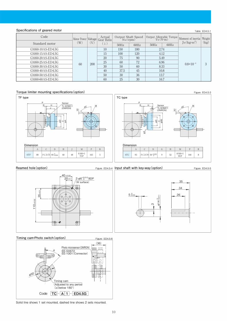
Table ED4.5-1
20060 0.8×10⁻⁴ 3
2025304050
75 605037.530
90 72 60 45 36
5.496.968.3310.813.7
15 100 120 4.1210 150 180 2.74
60 25 30 16.7
Specifications of geared motor
CodeVoltage(V)
Motor Power(W)
ActualGear Ratio( i )
Output Shaft SpeedNM(rpm)
50Hz 60Hz
Weight(kg)
Output Allowable TorqueTR(N・m)
50Hz 60Hz
Moment of inertiaJM(kg・m2)
GM60-20AS-ED4.5GGM60-25AS-ED4.5GGM60-30AS-ED4.5GGM60-40AS-ED4.5GGM60-50AS-ED4.5G
GM60-15AS-ED4.5GGM60-10AS-ED4.5G
GM60-60AS-ED4.5G
Standard motor
Solid line shows 1 set mounted, dashed line shows 2 sets mounted.
TF type TC type
A C D H J M P R
88 P.C.D.75 60 60 48 6-M6×17DP 165 56TF
DimensionA C D G H M P R
93 P.C.D.70 50 9 52 8-M6×19DP 160 86TC
Dimension
0-0.030 +0.025
0
45°HJ
φD C
(6)
RP
φA
TL-W3MC1(OMRON)
SensorM
45°H
C
(6)
RP
G
φ95
φA
φD
MSensorTL-W3MC1(OMRON)
Indexing period origin(0°)
Stop Position(6)M6×1, 10DP
P.C.D.40
T
S
U
V
dcba
※1(20)M8×1.25, 15DP
※2
RR
W
U
VS
φ80
0 -0.03
φ55
φ20
0 -0.013 170
170
40
8
10
50120
60
90
38
270
φ16
0 -0.011
φ20
48
210
220.5
105
15
55
5555
60
12146
1286
40 9612110
12 96 48 48
φ15
(Scribed line)
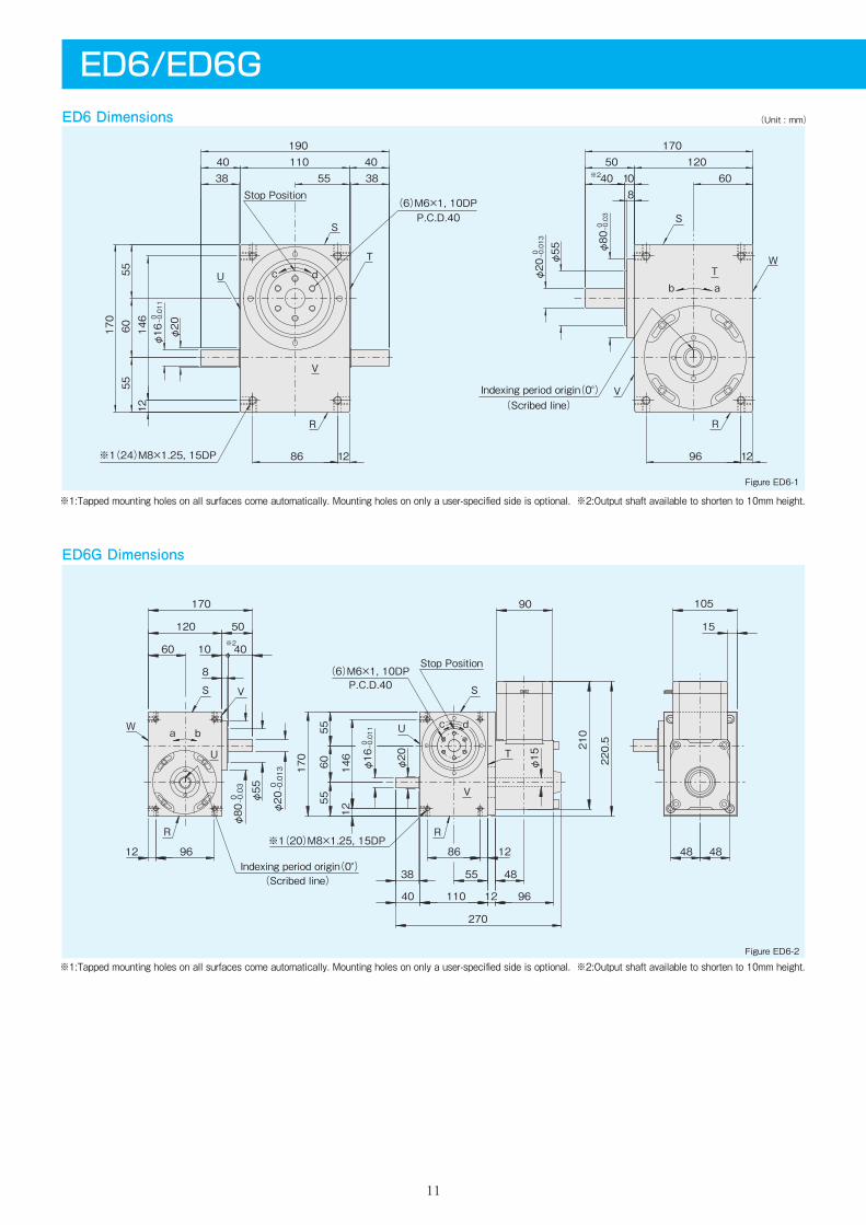
ED6G Dimensions
Figure ED6-1
Figure ED6-2
※1:Tapped mounting holes on all surfaces come automatically. Mounting holes on only a user-specified side is optional. ※2:Output shaft available to shorten to 10mm height.
※1:Tapped mounting holes on all surfaces come automatically. Mounting holes on only a user-specified side is optional. ※2:Output shaft available to shorten to 10mm height.
11
ED6/ED6GED6 Dimensions (Unit : mm)
6055
55146
12
96 1286 12
-0.013
0φ20φ55
-0.03
0φ80
170
8
12060
φ20-0.011
0φ16170
1904038 55
110 4038
501040
V
U
S
T
R
Tb a
W
S
V
R
Indexing period origin(0°)
P.C.D.40
※1(24)M8×1.25, 15DP
(6)M6×1, 10DPStop Position
dc
※2
(Scribed line)

12
Timing cam‐Photo switch(option)
Figure ED6-3
Figure ED6-5
Figure ED6-6
Code TC A 1 ED6G
Input shaft with key-way(option)
3 φ16
0 -0.011
5 0-0.03
40
38
30
Figure ED6-4Reamed hole(option)
2-φ6 9DP+0.012 0
(W surface)
58±0.0229±0.1
156±0.02
48±0.1
Torque limiter mounting specifications(option)
Photo microsensor(OMRON)EE-SX672EE-1001(Connector)
Timing cam(Adjusted to any period 〔α〕below 180°)
φ50
α
Table ED6-1
20090 1.2×10⁻⁴ 42025304050
75 605037.530
90 72 60 45 36
8.3310.812.716.720.6
15 100 120 6.1710 150 180 4.12
60 25 30 24.5
Specifications of geared motor
CodeVoltage(V)
Motor Power(W)
ActualGear Ratio( i )
Output Shaft SpeedNM(rpm)
50Hz 60Hz
Weight(kg)
Output Allowable TorqueTR(N・m)
50Hz 60Hz
Moment of inertiaJM(kg・m2)
GM90-20AS-ED6GGM90-25AS-ED6GGM90-30AS-ED6GGM90-40AS-ED6GGM90-50AS-ED6G
GM90-15AS-ED6GGM90-10AS-ED6G
GM90-60AS-ED6G
Standard motor
Solid line shows 1 set mounted, dashed line shows 2 sets mounted.
TF type TC type
A C D H J M P R
88 P.C.D.75 60 60 48 6-M6×17DP 195 56TF
DimensionA C D G H M P R
93 P.C.D.70 50 9 52 8-M6×19DP 192 106TC
Dimension
0-0.030 +0.025
0
45°H
P
J
φD C φA
R
(6)
MTL-W3MC1(OMRON)
Sensor45°
H
φA
G
φ95
P
φD C
R
(6)
MTL-W3MC1(OMRON)
Sensor
ED7G Dimensions
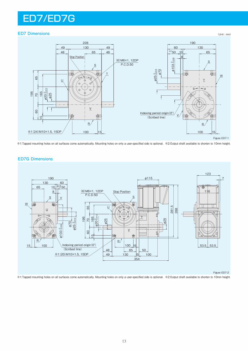
Figure ED7-1
Figure ED7-2
※1:Tapped mounting holes on all surfaces come automatically. Mounting holes on only a user-specified side is optional. ※2:Output shaft available to shorten to 10mm height.
※1:Tapped mounting holes on all surfaces come automatically. Mounting holes on only a user-specified side is optional. ※2:Output shaft available to shorten to 10mm height.
13
ED7/ED7GED7 Dimensions (Unit : mm)
7065
60165
15
6560 130
100 15100 15
50φ25
-0.013
0φ20195
65
-0.035
0φ103
φ70
-0.013
0φ25
190
108
228
4849 130 49
48
V
(6)M6×1, 12DP
※1(24)M10×1.5, 15DP
P.C.D.50
Stop Position
Indexing period origin(0°)V
R
W
b a
T
S
R
U
S
Tdc
※2
(Scribed line)
φ25
φ20
0 -0.013
φ103 0 -0.035 φ70
φ25
0 -0.013
53.553.5
7123
288
φ25
281.5
φ115
15
100354
1304948 65
6560
10
190
50
1565
7060
195
1550
165
10010015
8
130
116
※2
(Scribed line)Indexing period origin(0°)
dc
P.C.D.50(6)M6×1, 12DP Stop Position
T
R
U
S
V
※1(20)M10×1.5, 15DP
U
S
W
V
R
a b
14
Timing cam‐Photo switch(option)
A C D H J M P R
88 P.C.D.75 60 60 48 6-M6×17DP 205 5
128 P.C.D.95 75 70 55 6-M6×19DP 215 5
6TF
7TF
DimensionA C D G H M P R
93 P.C.D.70 50 9 52 8-M6×19DP 211 19
128 P.C.D.90 70 10 65 8-M8×1.2510DP
212 7
6TC
7TC
Dimension
Code TC A 1 ED7G
Input shaft with key-way(option)
3.5
φ20
0 -0.013
6 0-0.03
49
48
40
Figure ED7-3
Figure ED7-5
Figure ED7-6
Figure ED7-4Reamed hole(option)
2-φ6 9DP+0.012 0
(W surface)
80±0.0240±0.1
181±0.02
58±0.1
Torque limiter mounting specifications(option)
Timing cam(Adjusted to any period 〔α〕below 180°)
φ66
α
Photo microsensor(OMRON)EE-SX672EE-1001(Connector)
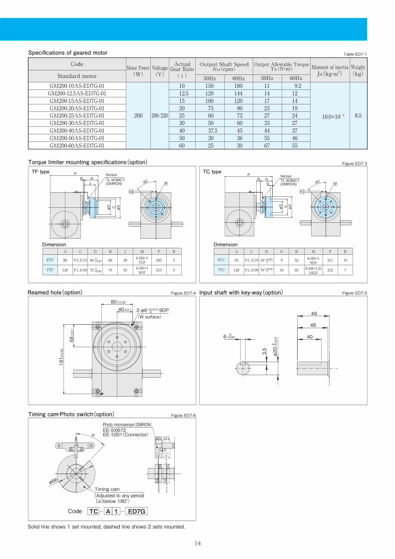
Table ED7-1
200/220200 10.0×10⁻⁴ 8.5
1520253040
100 75605037.5
120 90 72 60 45
1723273344
14 12.5 120 144 14 12 10 150 180 11 9.2
19 24 27 37
50 30 36 55 46 60 25 30 67 55
Specifications of geared motor
Code Voltage(V)
Motor Power(W)
ActualGear Ratio( i )
Output Shaft SpeedNM(rpm)
50Hz 60Hz
Weight(kg)
Output Allowable TorqueTR(N・m)
50Hz 60Hz
Moment of inertiaJM(kg・m2)
GM200-15AS-ED7G-01GM200-20AS-ED7G-01GM200-25AS-ED7G-01GM200-30AS-ED7G-01GM200-40AS-ED7G-01
GM200-12.5AS-ED7G-01GM200-10AS-ED7G-01
GM200-50AS-ED7G-01GM200-60AS-ED7G-01
Standard motor
Solid line shows 1 set mounted, dashed line shows 2 sets mounted.
0-0.030
0-0.030
+0.025 0
+0.030 0
TF type TC type
45°J
φAC
PHR
φD
(6)
M
SensorTL-W3MC1(OMRON) 45°
φAC
G
PHR
φD
(6)
M
SensorTL-W3MC1(OMRON)
ED8G Dimensions
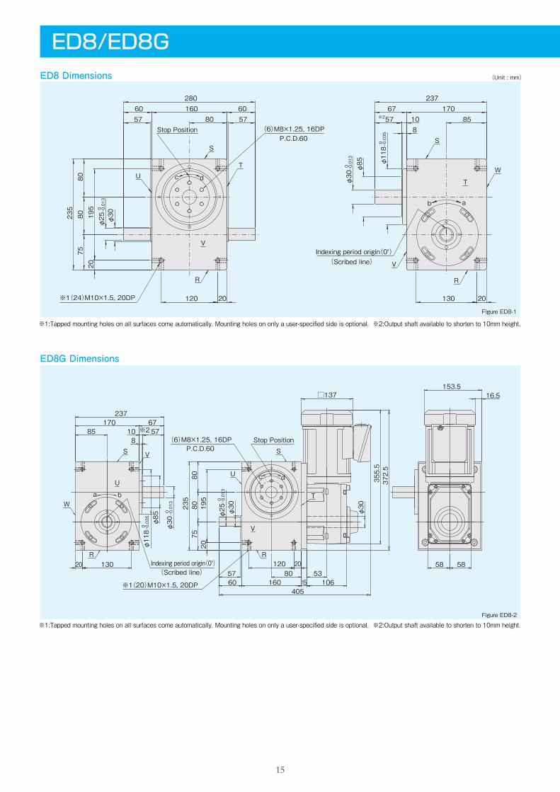
Figure ED8-1
Figure ED8-2
※1:Tapped mounting holes on all surfaces come automatically. Mounting holes on only a user-specified side is optional. ※2:Output shaft available to shorten to 10mm height.
※1:Tapped mounting holes on all surfaces come automatically. Mounting holes on only a user-specified side is optional. ※2:Output shaft available to shorten to 10mm height.
15
ED8/ED8GED8 Dimensions (Unit : mm)
120 20
195
2080
8075
8567 170
130 20
235
80160 6060
57
280
810
237
-0.013
0φ30φ85
-0.035
0φ118
-0.013
0φ25 φ30
5757
b a
※1(24)M10×1.5, 20DP
(6)M8×1.25, 16DPStop PositionP.C.D.60
Indexing period origin(0°)
dc
R
U
S
T
V
R
T
W
S
V
※2
(Scribed line)
φ118 0 -0.035
0 -0.013
φ85
φ30
φ25 φ30
5760 160 15
20
10 57
10653
237
13020
858
170 67
7580
16.5153.5
120
20195
80235
□137372.5
405
8058 58
φ30
355.5
dc
S
W
V
R
U
(Scribed line)
S
U
T
R
V
Stop PositionP.C.D.60
※2
Indexing period origin(0°)
※1(20)M10×1.5, 20DP
(6)M8×1.25, 16DP
a b
0 -0.013
16
Timing cam‐Photo switch(option)
A C D H J M P R
128 P.C.D.95 75 70 55 6-M6×19DP 255 5
164 P.C.D.120 100 82 65 6-M8×1.2511DP 267 5
7TF
8TF
DimensionA C D G H M P R
128 P.C.D.90 70 10 65 8-M8×1.2510DP 260 15
164 P.C.D.110 90 12 75 8-M8×1.2512DP 262 7
7TC
8TC
Dimension
Code TC A 1 ED8G
Input shaft with key-way(option)
4 φ25
0 -0.013
8 0-0.036
60
57
47
Figure ED8-3
Figure ED8-5
Figure ED8-6
Figure ED8-4Reamed hole(option)
2-φ8 12DP+0.015 0
(W surface)
90±0.0245±0.1
215±0.02
70±0.1
Torque limiter mounting specifications(option)
α
Timing cam(Adjusted to any period 〔α〕below 180°)
φ90
Photo microsensor(OMRON)EE-SX672EE-1001(Connector)
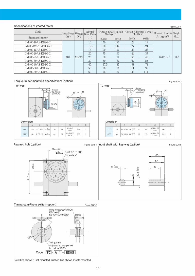
Table ED8-1
200/220400 15.0×10⁻⁴ 11.5
1520253040
100 75605037.5
120 90 72 60 45
3344556788
2712.5 120 144 27 2410 150 180 23 19
37465574
50 30 36 111 9260 25 30 133 111
Specifications of geared motor
Code Voltage(V)
Motor Power(W)
ActualGear Ratio( i )
Output Shaft SpeedNM(rpm)
50Hz 60Hz
Weight(kg)
Output Allowable TorqueTR(N・m)
50Hz 60Hz
Moment of inertiaJM(kg・m2)Standard motor
GM400-15AS-ED8G-01GM400-20AS-ED8G-01GM400-25AS-ED8G-01GM400-30AS-ED8G-01GM400-40AS-ED8G-01
GM400-12.5AS-ED8G-01GM400-10AS-ED8G-01
GM400-50AS-ED8G-01GM400-60AS-ED8G-01
Solid line shows 1 set mounted, dashed line shows 2 sets mounted.
0-0.030
0-0.035
+0.030 0
+0.035 0
TF type TC type
45°HJ
φACφD
PR
(6)
MSensorTL-W3MC1(OMRON)
45°HR
φD
G
φA
P
(6)
C
TL-W3MC1(OMRON)
SensorM
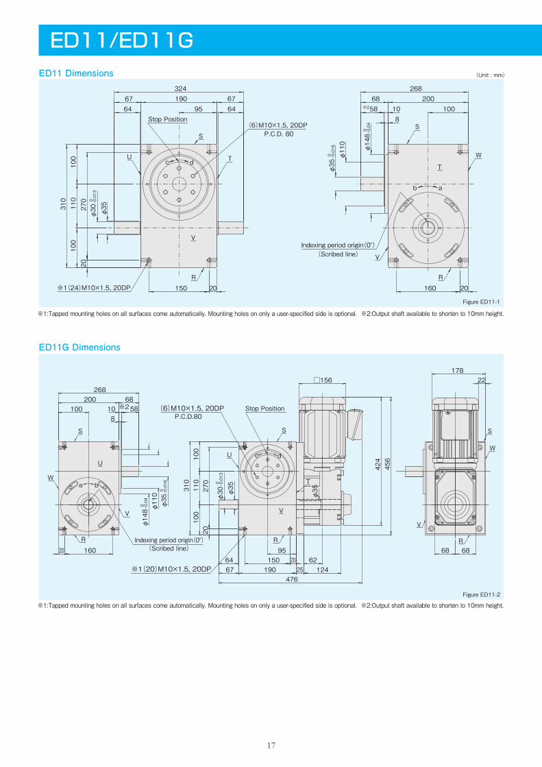
ED11G Dimensions
Figure ED11-1
Figure ED11-2
※1:Tapped mounting holes on all surfaces come automatically. Mounting holes on only a user-specified side is optional. ※2:Output shaft available to shorten to 10mm height.
※1:Tapped mounting holes on all surfaces come automatically. Mounting holes on only a user-specified side is optional. ※2:Output shaft available to shorten to 10mm height.
17
ED11/ED11GED11 Dimensions (Unit : mm)
160 20150 20
270
20110
100
310
100
586467
9519067
64
324
10020068
810
268-0.013
0φ30 φ35
-0.016
0φ35φ110
-0.04
0φ148P.C.D. 80
Indexing period origin(0°)
※1(24)M10×1.5, 20DP
(6)M10×1.5, 20DPStop Position
R
W
S
T
b a
R
T
V
U
S
dc
V
※2
(Scribed line)
686895
2520
1906764
424□156
φ148 0 -0.04
0 -0.016 0 -0.013
φ110
φ35
68
φ30 φ35
588
268200
100
20 160
310
100
110
100
20270
150
φ35
10
12462
456
476
22178
※2 (6)M10×1.5, 20DP
※1(20)M10×1.5, 20DP
Indexing period origin(0°)
Stop PositionP.C.D.80
c d
S S
T
U
R R
W
V
V
U
V
W
R
S
(Scribed line)
ba
18
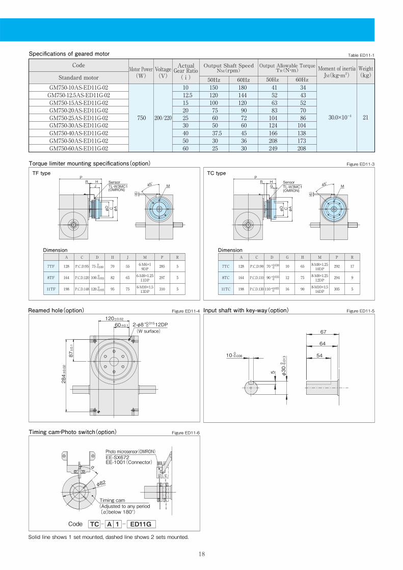
A C D H J M P R
128 P.C.D.95 75 70 55 6-M6×19DP 285 5
164 P.C.D.120 100 82 65 6-M8×1.2511DP 297 5
7TF
8TF
198 P.C.D.148 120 95 75 6-M10×1.513DP 310 511TF
DimensionA C D G H M P R
128 P.C.D.90 70 10 65 8-M8×1.2510DP
292 17
164 P.C.D.110 90 12 75 8-M8×1.2512DP 294 9
7TC
8TC
198 P.C.D.130 110 16 90 8-M10×1.516DP 305 511TC
Dimension
Timing cam‐Photo switch(option)
Code TC A 1 ED11G
Input shaft with key-way(option)
5 300 -0.013
φ
10 0-0.036
67
64
54
Figure ED11-3
Figure ED11-5
Figure ED11-6
Figure ED11-4Reamed hole(option)120±0.02
60±0.1
284±0.02
87±0.1
2-φ8 12DP+0.015 0
(W surface)
Torque limiter mounting specifications(option)
α
82φ
Timing cam(Adjusted to any period 〔α〕below 180°)
Photo microsensor(OMRON)EE-SX672EE-1001(Connector)
Table ED11-1
200/220750 30.0×10⁻⁴ 21
1520253040
100 75605037.5
120 90 72 60 45
6383104124166
5212.5 120 144 52 4310 150 180 41 34
7086104138
50 30 36 208 17360 25 30 249 208
Specifications of geared motor
Code Voltage(V)
Motor Power(W)
ActualGear Ratio( i )
Output Shaft SpeedNM(rpm)
50Hz 60Hz
Weight(kg)
Output Allowable TorqueTR(N・m)
50Hz 60Hz
Moment of inertiaJM(kg・m2)
GM750-15AS-ED11G-02GM750-20AS-ED11G-02GM750-25AS-ED11G-02GM750-30AS-ED11G-02GM750-40AS-ED11G-02
GM750-12.5AS-ED11G-02GM750-10AS-ED11G-02
GM750-50AS-ED11G-02GM750-60AS-ED11G-02
Standard motor
Solid line shows 1 set mounted, dashed line shows 2 sets mounted.
0-0.030
0-0.035
0-0.035
+0.030 0
+0.035 0
+0.035 0
TF type TC type
45°
(6)
φD C φA
JHR
PSensorTL-W3MC1(OMRON)
M 45°
(6)
φD C φA
GHR
PSensorTL-W3MC1(OMRON)
M
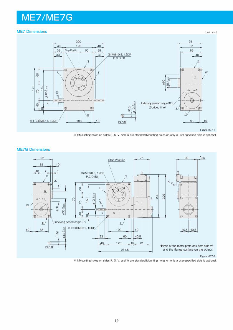
ME7G Dimensions
Figure ME7-1
Figure ME7-2
※1:Mounting holes on sides R, S, V, and W are standard.Mounting holes on only a user-specified side is optional.
※1:Mounting holes on sides R, S, V, and W are standard.Mounting holes on only a user-specified side is optional.
ME7/ME7GME7 Dimensions (Unit : mm)
INPUT
b a
dc T
R
V
W
S
Indexing period origin(0°)
V
R
U T
S
(6)M5×0.8, 12DP
※1(24)M6×1, 12DP
Stop Position
P.C.D.50
φ12
0 -0.018
(0.5)
1065
φ60
φ35
0 -0.025
40858795
10100
φ12
0 -0.018
φ15
170
10150
333338 3840 40
200120
60
6040
70
(Scribed line)
P.C.D.50(6)M5×0.8, 12DP
V
Stop Position
R
T
U
S
c d
Indexing period origin(0°)R
a b
U
W
SV
※1(20)M6×1, 12DP
INPUT
33
95
85
40
12
0.5★
208
209
φ35
0 -0.025
φ60
φ12
0 -0.018
φ15170
76
261.5
40.560φ12
0 -0.018
(0.5)
2 8
10
99
40.5 40.510 65
4060
70
10150
40 8110120
10100
★
★Part of the motor protrudes from side W and the flange surface on the output.
19
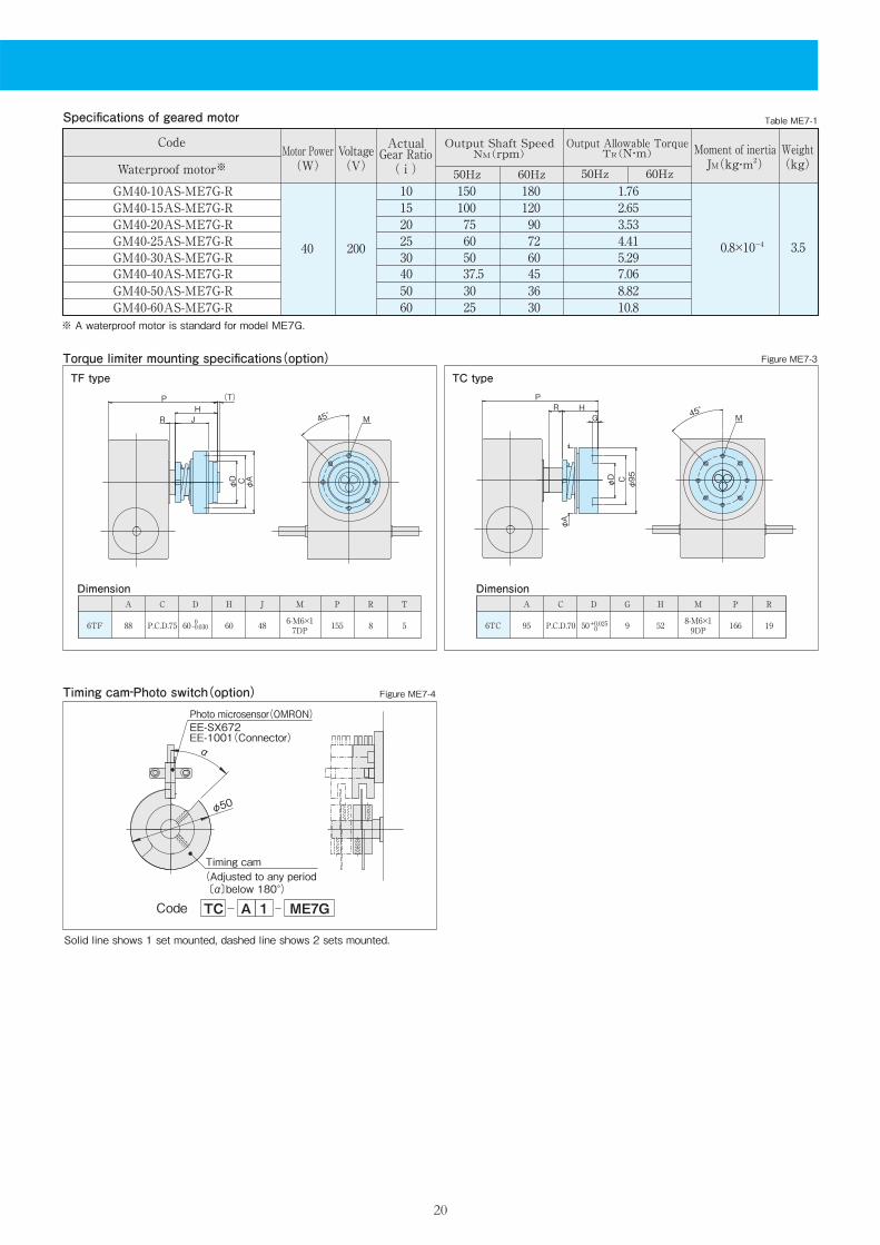
Table ME7-1Specifications of geared motor
ActualGear Ratio( i )
Output Shaft SpeedNM(rpm)
50Hz 60Hz
Weight(kg)
Output Allowable TorqueTR(N・m)
50Hz 60Hz
20040 0.8×10⁻⁴ 3.5
2025304050
75 605037.530
90 72 60 45 36
3.534.415.297.068.82
15 100 120 2.6510 150 180 1.76
Moment of inertiaJM(kg・m2)
GM40-20AS-ME7G-RGM40-25AS-ME7G-RGM40-30AS-ME7G-RGM40-40AS-ME7G-RGM40-50AS-ME7G-R
GM40-15AS-ME7G-RGM40-10AS-ME7G-R
GM40-60AS-ME7G-R 60 25 30 10.8
Code
Waterproof motor※Voltage(V)
Motor Power(W)
Torque limiter mounting specifications(option)
Dimension Dimension
Timing cam‐Photo switch(option)
A C D H J M P R
88 P.C.D.75 60 60 48 6-M6×17DP 155
T
586TF
A C D G H M P R
95 P.C.D.70 50 9 52 8-M6×19DP 166 196TC
Code TC A 1 ME7G
Figure ME7-3
Figure ME7-4
φ50
α
Photo microsensor(OMRON)EE-SX672EE-1001(Connector)
Timing cam(Adjusted to any period 〔α〕below 180°)
Solid line shows 1 set mounted, dashed line shows 2 sets mounted.
20
0-0.030 +0.025
0
※ A waterproof motor is standard for model ME7G.
TF type TC type
45°
φD C φA
P (T)
R JH
M45°
φD C
φ95
PR H
G
φA
M


![N r G s · 2021. 1. 21. · G r r x s r ~t Z ( ] o Á ] Z } Á U 2 X 2 r 3 v U x X í ô9 ì. ^ : { s x s _ rs X s v' } P Z í ô ô ñ 4 { v r X X X G A { r v v x õ](https://static.fdocument.org/doc/165x107/6102738e79d2112f03059c6e/n-r-g-s-2021-1-21-g-r-r-x-s-r-t-z-o-z-u-2-x-2-r-3-v-u-x-x-.jpg)