ECE112 - Lab 7 - Oregon State Universityweb.engr.oregonstate.edu/~traylor/ece112/labs/lab7.pdfECE112...
4
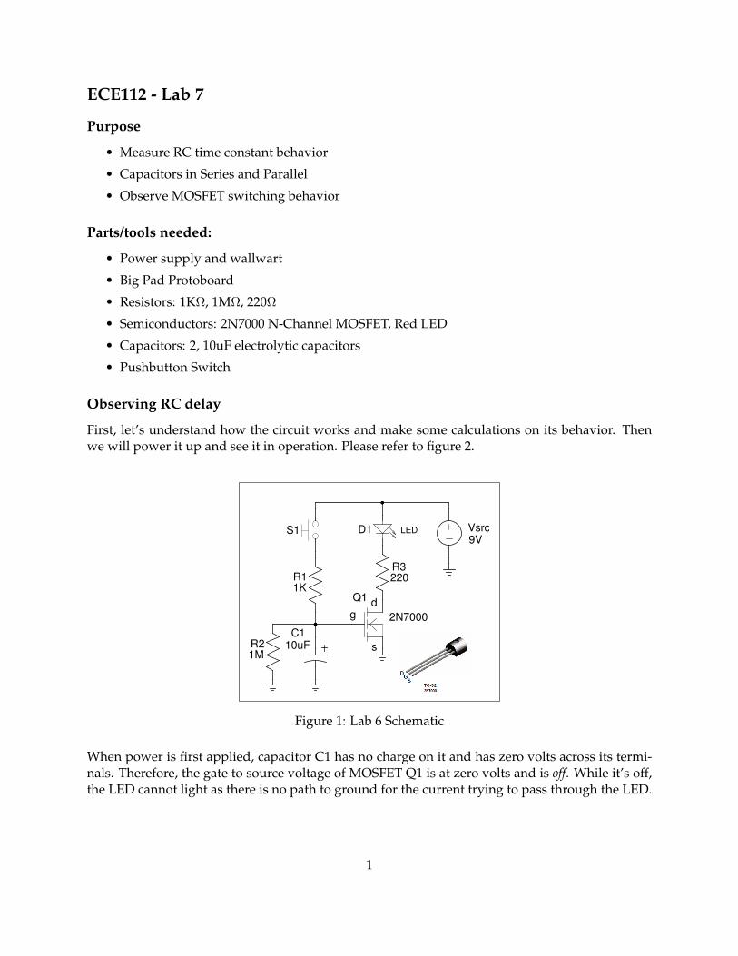
ECE112 - Lab 7 Purpose • Measure RC time constant behavior • Capacitors in Series and Parallel • Observe MOSFET switching behavior Parts/tools needed: • Power supply and wallwart • Big Pad Protoboard • Resistors: 1KΩ, 1MΩ, 220Ω • Semiconductors: 2N7000 N-Channel MOSFET, Red LED • Capacitors: 2, 10uF electrolytic capacitors • Pushbutton Switch Observing RC delay First, let’s understand how the circuit works and make some calculations on its behavior. Then we will power it up and see it in operation. Please refer to figure 2. Vsrc 9V R1 1K S1 g d s Q1 2N7000 R3 220 D1 LED C1 10uF R2 1M Figure 1: Lab 6 Schematic When power is first applied, capacitor C1 has no charge on it and has zero volts across its termi- nals. Therefore, the gate to source voltage of MOSFET Q1 is at zero volts and is off. While it’s off, the LED cannot light as there is no path to ground for the current trying to pass through the LED. 1
Transcript of ECE112 - Lab 7 - Oregon State Universityweb.engr.oregonstate.edu/~traylor/ece112/labs/lab7.pdfECE112...
ECE112 - Lab 7
Purpose
• Measure RC time constant behavior
• Capacitors in Series and Parallel
• Observe MOSFET switching behavior
Parts/tools needed:
• Power supply and wallwart
• Big Pad Protoboard
• Resistors: 1KΩ, 1MΩ, 220Ω
• Semiconductors: 2N7000 N-Channel MOSFET, Red LED
• Capacitors: 2, 10uF electrolytic capacitors
• Pushbutton Switch
Observing RC delay
First, let’s understand how the circuit works and make some calculations on its behavior. Thenwe will power it up and see it in operation. Please refer to figure 2.
Vsrc9V
R11K
S1
gd
s
Q1
2N7000
R3220
D1 LED
C110uFR2
1M
a
Figure 1: Lab 6 Schematic
When power is first applied, capacitor C1 has no charge on it and has zero volts across its termi-nals. Therefore, the gate to source voltage of MOSFET Q1 is at zero volts and is off. While it’s off,the LED cannot light as there is no path to ground for the current trying to pass through the LED.
1
When the pushbutton is pressed, C1 will charge quickly through resistor R1. The time constantfor charging, τ is determined by the value of R1 and capacitor C1. Calculate this time constantbelow.
Take note that the tolerance of the capacitor (±20%) may give quite a variation in the observedtime constant. However, typical values are often quite close to those stated for the part.
If the pushbutton is depressed for say 10τ , the voltage on the positive end of the capacitor and theMOSFET gate will rise beyond the gate-source on voltage so that the resistance between the drainand source terminals will become very small and the LED will illuminate.
Once the pushbutton is released, the capacitor will begin to slowly discharge through the 1Mresistor since the pushbutton is an open circuit and no current can flow into the gate of Q1. Thetime constant for the discharge of the capacitor is determined by the 1M resistor and the 10ufcapacitor. However, Q1 will remain on until the voltage between its gate and source terminalsfalls below about 2 volts. Calculate the amount of time it will take for the LED to go out once thepushbutton is released.
Test the Theory
1. Build the circuit shown in figure 2 on the big pad protoboard.2. Plug your power supply into the power buses on the protoboard.3. Plug the wallwart into your power supply. Initially, the LED should be off. If not, something iswired wrong.4. Briefly depress and release the pushbutton. The LED should light immediately as the capacitorcharges quickly through R1 and Q1 turns on. Once the pushbutton is released, the voltage on thecapacitor will decay below the MOSFET threshold voltage and the LED will go out. Using sometiming device, measure the delay from pushbutton release to the LED turning off.
2
Delay from pushbutton release to LED going out:
5. Now, modify your circuit by putting the second 10uF capacitor in series with the first one. Besure to observe proper polarity for the second capacitor. Both capacitors will have their positiveends oriented away from ground.
Delay from pushbutton release to LED going out (caps in series):
6. Now put the two capacitors in parallel and do the test in step 4 again.
Delay from pushbutton release to LED going out (caps in parallel):
Which connection of capacitors gave the biggest delay and why?
7. We would like to measure the resistance of the MOSFET in both on and off states, remember-ing that it should approximate a real switch. Thus, the resistance drain to source of the MOSFETshould be:
-if off : nearly infinite ohms-if on: a few ohms, probably < 10
To measure off resistance:Power must be disconnected (not just cut off) from the circuit, otherwise you will be measuringthe resistance through the power supply. Make sure the MOSFET gate is at zero volts by brieflyshorting the gate terminal to ground. Then connecting the positive lead of the ohmmeter to thedrain and the negative lead to the source, you can directly measure the resistance.
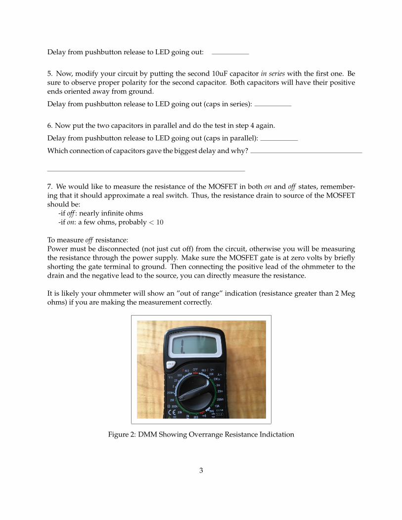
It is likely your ohmmeter will show an ”out of range” indication (resistance greater than 2 Megohms) if you are making the measurement correctly.
Figure 2: DMM Showing Overrange Resistance Indictation
3
6a. Measure the off resistance of the MOSFET.
Off resistance of Q1:
To measure on resistance:MOSFET on resistance cannot be directly measured but is computed. We determine the on resis-tance by measuring the voltage from drain to source and then the current (drain to source) throughthe device. Using Ohm’s law R = V
I , we can determine the resistance. You do not need to breakthe circuit to make the current measurement. The current through the 220 ohm resistor is identical
to the MOSFET drain current. Thus, the drain current Id through the MOSFET is Id =Vr3220
.
Clearly, on resistance must be measured while the circuit is on. In addition, you will need to con-tinuously hold the pushbutton down. If you push and release it, the voltage on the gate terminalwill begin to creep down as the capacitor discharges and the resistance of the MOSFET will change.
6b. Making the on resistance measurement:
Voltage, drain to source of Q1:
Current through 220 ohm resistor (show calculation):
On resistance of MOSFET (show calculation) :
7. Have your TA check off your work.
4


![Edc Lab Manuals[1]](https://static.fdocument.org/doc/165x107/5514bf77497959ee1d8b487c/edc-lab-manuals1.jpg)