budynas SM ch13 - Oakland Universitylatcha/me486/SM/budynas_SM_ch13.pdfbudynas_SM_ch13.qxd 1/29/07...
24
Chapter 13 13-1 d P = 17/8 = 2.125 in d G = N 2 N 3 d P = 1120 544 (2.125) = 4.375 in N G = Pd G = 8(4.375) = 35 teeth Ans. C = (2.125 + 4.375) /2 = 3.25 in Ans. 13-2 n G = 1600(15/60) = 400 rev/min Ans. p = π m = 3π mm Ans. C = [3(15 + 60)]/2 = 112.5 mm Ans. 13-3 N G = 20(2.80) = 56 teeth Ans. d G = N G m = 56(4) = 224 mm Ans. d P = N P m = 20(4) = 80 mm Ans. C = (224 + 80) /2 = 152 mm Ans. 13-4 Mesh: a = 1/ P = 1/3 = 0.3333 in Ans. b = 1.25/ P = 1.25/3 = 0.4167 in Ans. c = b − a = 0.0834 in Ans. p = π/ P = π/3 = 1.047 in Ans. t = p/2 = 1.047/2 = 0.523 in Ans. Pinion Base-Circle: d 1 = N 1 / P = 21/3 = 7 in d 1b = 7 cos 20° = 6.578 in Ans. Gear Base-Circle: d 2 = N 2 / P = 28/3 = 9.333 in d 2b = 9.333 cos 20° = 8.770 in Ans. Base pitch: p b = p c cos φ = ( π/3) cos 20° = 0.984 in Ans. Contact Ratio: m c = L ab / p b = 1.53/0.984 = 1.55 Ans. See the next page for a drawing of the gears and the arc lengths. budynas_SM_ch13.qxd 1/29/07 7:06 PM Page 325
Transcript of budynas SM ch13 - Oakland Universitylatcha/me486/SM/budynas_SM_ch13.pdfbudynas_SM_ch13.qxd 1/29/07...

Chapter 13
13-1
dP = 17/8 = 2.125 in
dG = N2
N3dP = 1120
544(2.125) = 4.375 in
NG = PdG = 8(4.375) = 35 teeth Ans.
C = (2.125 + 4.375)/2 = 3.25 in Ans.
13-2
nG = 1600(15/60) = 400 rev/min Ans.
p = πm = 3π mm Ans.
C = [3(15 + 60)]/2 = 112.5 mm Ans.
13-3NG = 20(2.80) = 56 teeth Ans.
dG = NGm = 56(4) = 224 mm Ans.
dP = NPm = 20(4) = 80 mm Ans.
C = (224 + 80)/2 = 152 mm Ans.
13-4 Mesh: a = 1/P = 1/3 = 0.3333 in Ans.
b = 1.25/P = 1.25/3 = 0.4167 in Ans.
c = b − a = 0.0834 in Ans.
p = π/P = π/3 = 1.047 in Ans.
t = p/2 = 1.047/2 = 0.523 in Ans.
Pinion Base-Circle: d1 = N1/P = 21/3 = 7 in
d1b = 7 cos 20° = 6.578 in Ans.
Gear Base-Circle: d2 = N2/P = 28/3 = 9.333 in
d2b = 9.333 cos 20° = 8.770 in Ans.
Base pitch: pb = pc cos φ = (π/3) cos 20° = 0.984 in Ans.
Contact Ratio: mc = Lab/pb = 1.53/0.984 = 1.55 Ans.
See the next page for a drawing of the gears and the arc lengths.
budynas_SM_ch13.qxd 1/29/07 7:06 PM Page 325
326 Solutions Manual • Instructor’s Solution Manual to Accompany Mechanical Engineering Design
13-5
(a) AO =[(
14/6
2
)2
+(
32/6
2
)2]1/2
= 2.910 in Ans.
(b) γ = tan−1(14/32) = 23.63° Ans.
� = tan−1(32/14) = 66.37° Ans.
(c) dP = 14/6 = 2.333 in,
dG = 32/6 = 5.333 in Ans.
(d) From Table 13-3, 0.3AO = 0.873 in and 10/P = 10/6 = 1.67
0.873 < 1.67 ∴ F = 0.873 in Ans.
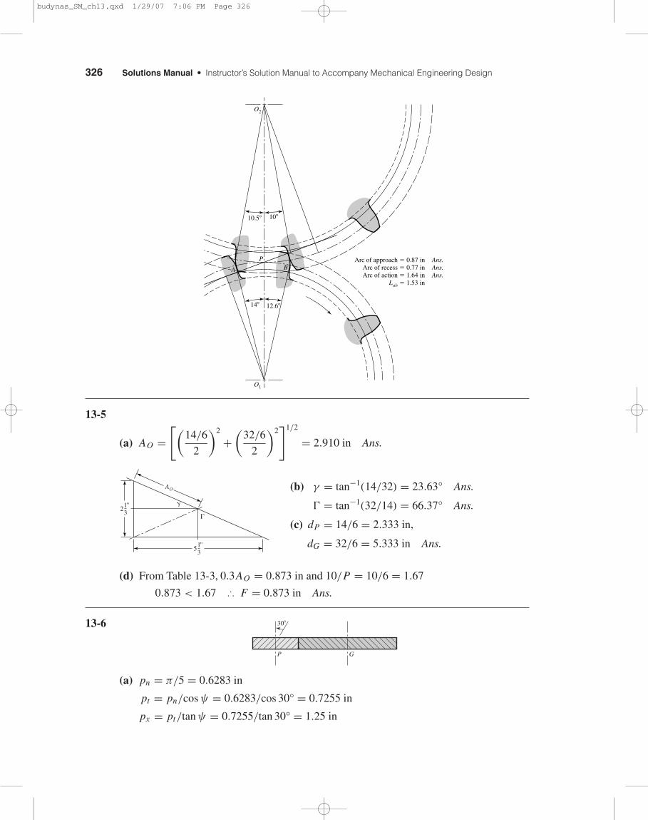
13-6
(a) pn = π/5 = 0.6283 in
pt = pn/cos ψ = 0.6283/cos 30° = 0.7255 in
px = pt/tan ψ = 0.7255/tan 30° = 1.25 in
30�
P G
213"
513"
AO
�
�
10.5�
Arc of approach � 0.87 in Ans.Arc of recess � 0.77 in Ans.Arc of action � 1.64 in Ans.
Lab � 1.53 in
10�
O2
O1
14� 12.6�
PBA
budynas_SM_ch13.qxd 1/29/07 7:06 PM Page 326
Chapter 13 327
(b) Eq. (13-7): pnb = pn cos φn = 0.6283 cos 20° = 0.590 in Ans.
(c) Pt = Pn cos ψ = 5 cos 30° = 4.33 teeth/in
φt = tan−1(tan φn/cos ψ) = tan−1(tan 20°/cos 30◦) = 22.8° Ans.
(d) Table 13-4:
a = 1/5 = 0.200 in Ans.
b = 1.25/5 = 0.250 in Ans.
dP = 17
5 cos 30°= 3.926 in Ans.
dG = 34
5 cos 30°= 7.852 in Ans.
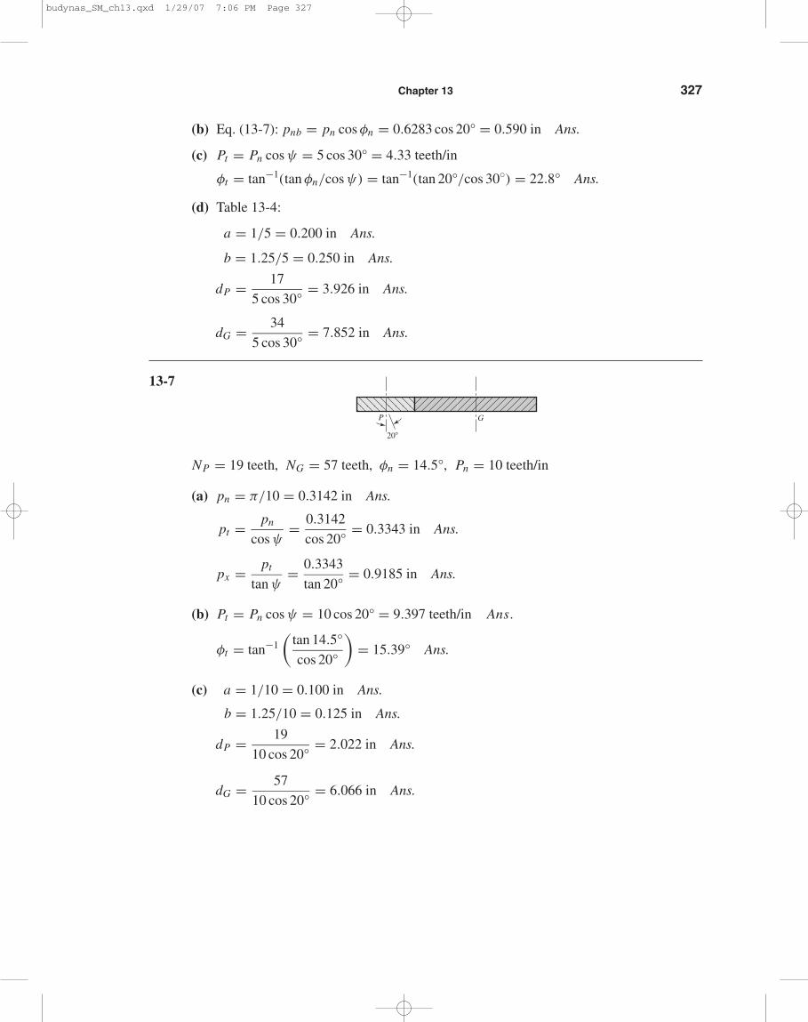
13-7
NP = 19 teeth, NG = 57 teeth, φn = 14.5°, Pn = 10 teeth/in
(a) pn = π/10 = 0.3142 in Ans.
pt = pn
cos ψ= 0.3142
cos 20°= 0.3343 in Ans.
px = pt
tan ψ= 0.3343
tan 20°= 0.9185 in Ans.
(b) Pt = Pn cos ψ = 10 cos 20° = 9.397 teeth/in Ans.
φt = tan−1(
tan 14.5°
cos 20°
)= 15.39° Ans.
(c) a = 1/10 = 0.100 in Ans.
b = 1.25/10 = 0.125 in Ans.
dP = 19
10 cos 20°= 2.022 in Ans.
dG = 57
10 cos 20°= 6.066 in Ans.
G
20�
P
budynas_SM_ch13.qxd 1/29/07 7:06 PM Page 327
328 Solutions Manual • Instructor’s Solution Manual to Accompany Mechanical Engineering Design
13-8 (a) The smallest pinion tooth count that will run with itself is found from Eq. (13-10)
NP ≥ 2k
3 sin2 φ
(1 +
√1 + 3 sin2 φ
)
≥ 2(1)
3 sin2 20°
(1 +
√1 + 3 sin2 20°
)≥ 12.32 → 13 teeth Ans.
(b) The smallest pinion that will mesh with a gear ratio of mG = 2.5, from Eq. (13-11) is
NP ≥ 2(1)
[1 + 2(2.5)] sin2 20°
{2.5 +
√2.52 + [1 + 2(2.5)] sin2 20°
}
≥ 14.64 → 15 pinion teeth Ans.
The largest gear-tooth count possible to mesh with this pinion, from Eq. (13-12) is
NG ≤ N 2P sin2 φ − 4k2
4k − 2NP sin2 φ
≤ 152 sin2 20° − 4(1)2
4(1) − 2(15) sin2 20°
≤ 45.49 → 45 teeth Ans.
(c) The smallest pinion that will mesh with a rack, from Eq. (13-13)
NP ≥ 2k
sin2 φ= 2(1)
sin2 20°
≥ 17.097 → 18 teeth Ans.
13-9 φn = 20°, ψ = 30°, φt = tan−1 (tan 20°/cos 30°) = 22.80°
(a) The smallest pinion tooth count that will run itself is found from Eq. (13-21)
NP ≥ 2k cos ψ
3 sin2 φt
(1 +
√1 + 3 sin2 φt
)
≥ 2(1) cos 30°
3 sin2 22.80°
(1 +
√1 + 3 sin2 22.80°
)≥ 8.48 → 9 teeth Ans.
(b) The smallest pinion that will mesh with a gear ratio of m = 2.5, from Eq. (13-22) is
NP ≥ 2(1) cos 30°
[1 + 2(2.5)] sin2 22.80°
{2.5 +
√2.52 + [1 + 2(2.5)] sin2 22.80°
}≥ 9.95 → 10 teeth Ans.
The largest gear-tooth count possible to mesh with this pinion, from Eq. (13-23) is
NG ≤ 102 sin2 22.80° − 4(1) cos2 30°
4(1) cos2 30° − 2(20) sin2 22.80°
≤ 26.08 → 26 teeth Ans.
budynas_SM_ch13.qxd 1/29/07 7:06 PM Page 328
Chapter 13 329
(c) The smallest pinion that will mesh with a rack, from Eq. (13-24) is
NP ≥ 2(1) cos 30°
sin2 22.80°
≥ 11.53 → 12 teeth Ans.
13-10 Pressure Angle: φt = tan−1(
tan 20°
cos 30°
)= 22.796°
Program Eq. (13-24) on a computer using a spreadsheet or code and increment NP . Thefirst value of NP that can be doubled is NP = 10 teeth, where NG ≤ 26.01 teeth. So NG =20 teeth will work. Higher tooth counts will work also, for example 11:22, 12:24, etc.
Use 10:20 Ans.
13-11 Refer to Prob. 13-10 solution. The first value of NP that can be multiplied by 6 isNP = 11 teeth where NG ≤ 93.6 teeth. So NG = 66 teeth.
Use 11:66 Ans.
13-12 Begin with the more general relation, Eq. (13-24), for full depth teeth.
NG = N 2P sin2 φt − 4 cos2 ψ
4 cos ψ − 2NP sin2 φt
For a rack, set the denominator to zero4 cos ψ − 2NP sin2 φt = 0
From which
sin φt =√
2 cos ψ
NP
φt = sin−1
√2 cos ψ
NP
For NP = 9 teeth and ψ = 0 for spur gears,
φt = sin−1
√2(1)
9= 28.126° Ans.
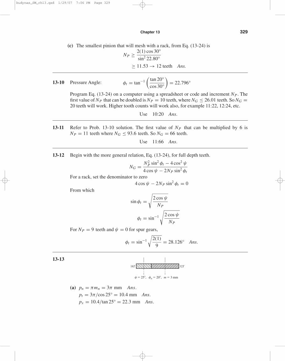
13-13
(a) pn = πmn = 3π mm Ans.
pt = 3π/cos 25° = 10.4 mm Ans.
px = 10.4/tan 25° = 22.3 mm Ans.
18T 32T
� � 25�, �n � 20�, m � 3 mm
budynas_SM_ch13.qxd 1/29/07 7:06 PM Page 329
330 Solutions Manual • Instructor’s Solution Manual to Accompany Mechanical Engineering Design
(b) mt = 10.4/π = 3.310 mm Ans.
φt = tan−1 tan 20°
cos 25°= 21.88° Ans.
(c) dP = 3.310(18) = 59.58 mm Ans.
dG = 3.310(32) = 105.92 mm Ans.
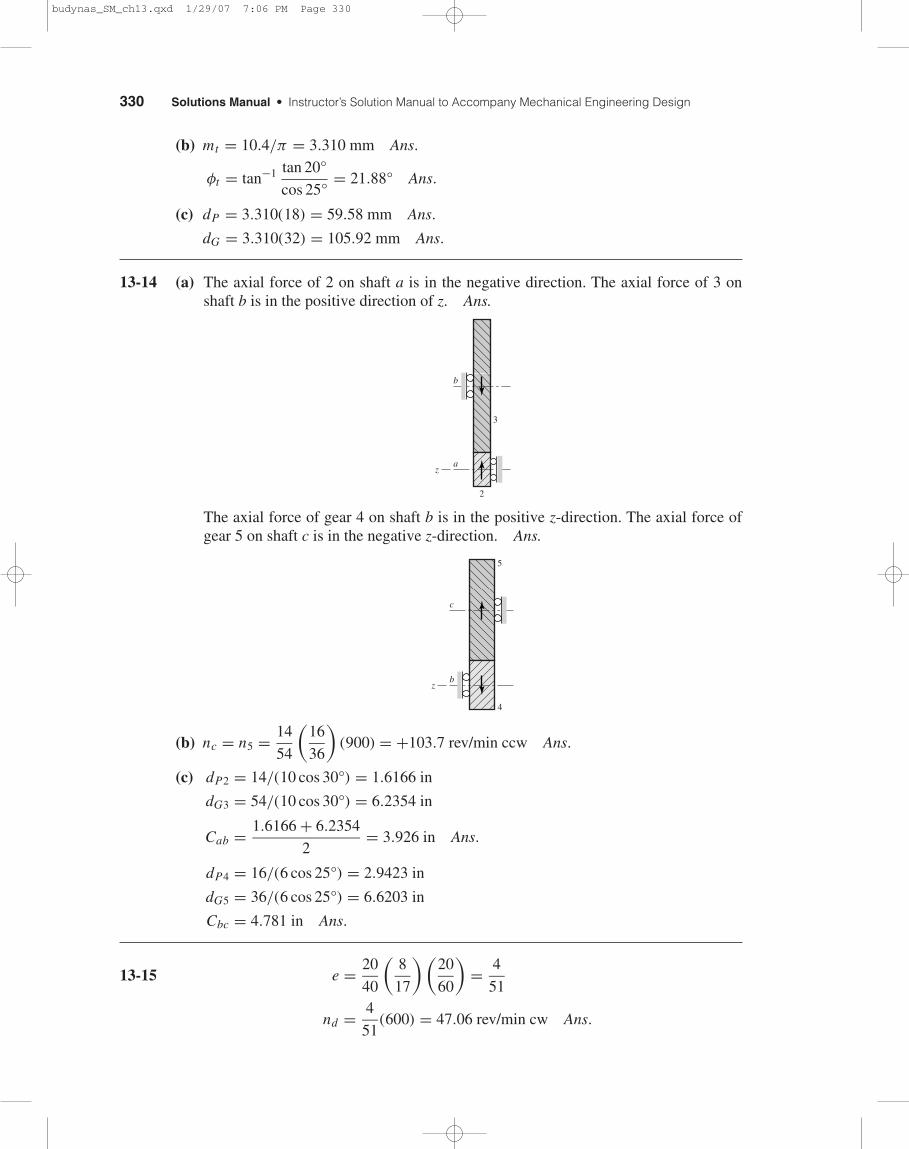
13-14 (a) The axial force of 2 on shaft a is in the negative direction. The axial force of 3 onshaft b is in the positive direction of z. Ans.
The axial force of gear 4 on shaft b is in the positive z-direction. The axial force ofgear 5 on shaft c is in the negative z-direction. Ans.
(b) nc = n5 = 14
54
(16
36
)(900) = +103.7 rev/min ccw Ans.
(c) dP2 = 14/(10 cos 30°) = 1.6166 in
dG3 = 54/(10 cos 30°) = 6.2354 in
Cab = 1.6166 + 6.2354
2= 3.926 in Ans.
dP4 = 16/(6 cos 25°) = 2.9423 in
dG5 = 36/(6 cos 25°) = 6.6203 in
Cbc = 4.781 in Ans.
13-15 e = 20
40
(8
17
)(20
60
)= 4
51
nd = 4
51(600) = 47.06 rev/min cw Ans.
5
4
c
bz
a
3
z
2
b
budynas_SM_ch13.qxd 1/29/07 7:06 PM Page 330
Chapter 13 331
13-16
e = 6
10
(18
38
)(20
48
)(3
36
)= 3
304
na = 3
304(1200) = 11.84 rev/min cw Ans.
13-17
(a) nc = 12
40· 1
1(540) = 162 rev/min cw about x . Ans.
(b) dP = 12/(8 cos 23°) = 1.630 in
dG = 40/(8 cos 23°) = 5.432 in
dP + dG
2= 3.531 in Ans.
(c) d = 32
4= 8 in at the large end of the teeth. Ans.
13-18 (a) The planet gears act as keys and the wheel speeds are the same as that of the ring gear.Thus
n A = n3 = 1200(17/54) = 377.8 rev/min Ans.
(b) nF = n5 = 0, nL = n6, e = −1
−1 = n6 − 377.8
0 − 377.8
377.8 = n6 − 377.8
n6 = 755.6 rev/min Ans.
Alternatively, the velocity of the center of gear 4 is v4c ∝ N6n3 . The velocity of theleft edge of gear 4 is zero since the left wheel is resting on the ground. Thus, the ve-locity of the right edge of gear 4 is 2v4c ∝ 2N6n3. This velocity, divided by the radiusof gear 6 ∝ N6, is angular velocity of gear 6–the speed of wheel 6.
∴ n6 = 2N6n3
N6= 2n3 = 2(377.8) = 755.6 rev/min Ans.
(c) The wheel spins freely on icy surfaces, leaving no traction for the other wheel. Thecar is stalled. Ans.
13-19 (a) The motive power is divided equally among four wheels instead of two.
(b) Locking the center differential causes 50 percent of the power to be applied to therear wheels and 50 percent to the front wheels. If one of the rear wheels, rests ona slippery surface such as ice, the other rear wheel has no traction. But the frontwheels still provide traction, and so you have two-wheel drive. However, if the reardifferential is locked, you have 3-wheel drive because the rear-wheel power is nowdistributed 50-50.
budynas_SM_ch13.qxd 1/29/07 7:06 PM Page 331
332 Solutions Manual • Instructor’s Solution Manual to Accompany Mechanical Engineering Design
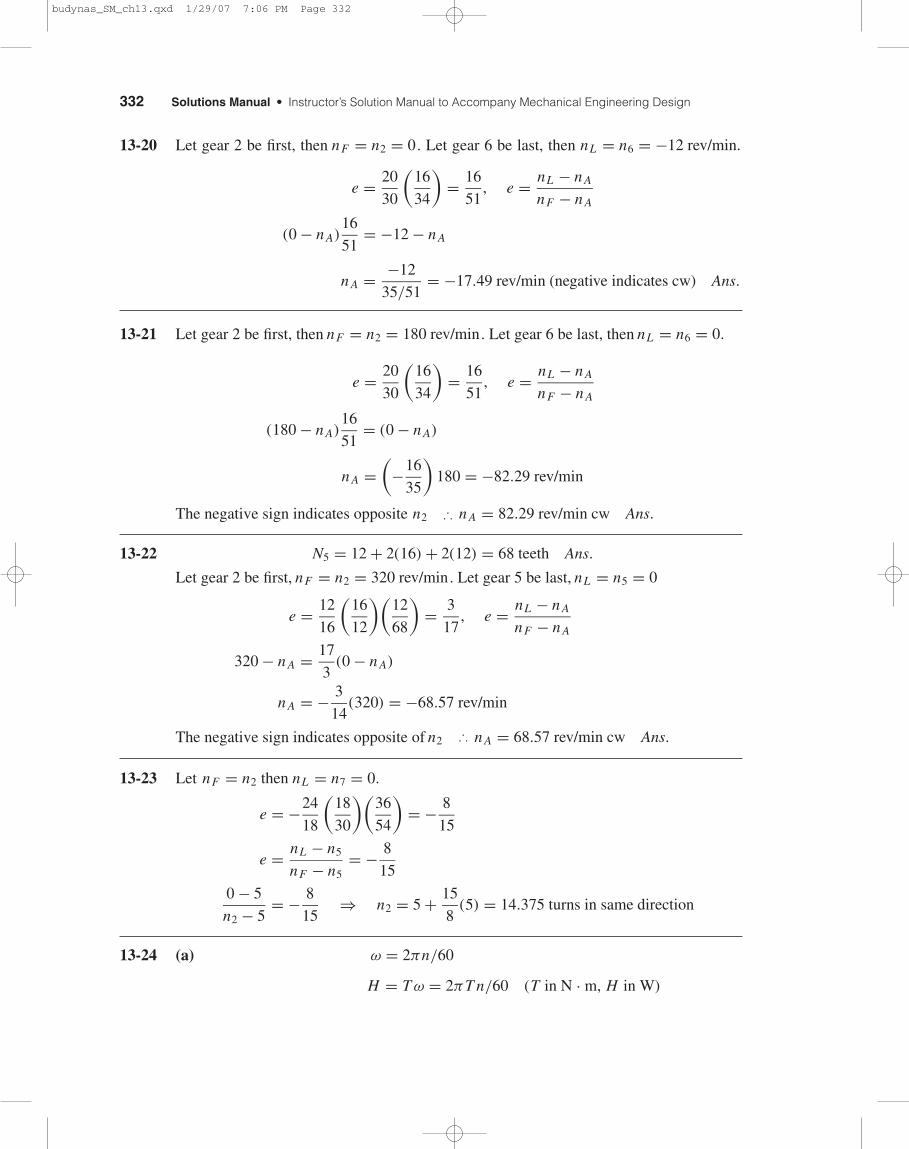
13-20 Let gear 2 be first, then nF = n2 = 0. Let gear 6 be last, then nL = n6 = −12 rev/min.
e = 20
30
(16
34
)= 16
51, e = nL − n A
nF − n A
(0 − n A)16
51= −12 − n A
n A = −12
35/51= −17.49 rev/min (negative indicates cw) Ans.
13-21 Let gear 2 be first, then nF = n2 = 180 rev/min. Let gear 6 be last, then nL = n6 = 0.
e = 20
30
(16
34
)= 16
51, e = nL − n A
nF − n A
(180 − n A)16
51= (0 − n A)
n A =(
−16
35
)180 = −82.29 rev/min
The negative sign indicates opposite n2 ∴ n A = 82.29 rev/min cw Ans.
13-22 N5 = 12 + 2(16) + 2(12) = 68 teeth Ans.
Let gear 2 be first, nF = n2 = 320 rev/min. Let gear 5 be last, nL = n5 = 0
e = 12
16
(16
12
)(12
68
)= 3
17, e = nL − n A
nF − n A
320 − n A = 17
3(0 − n A)
n A = − 3
14(320) = −68.57 rev/min
The negative sign indicates opposite of n2 ∴ n A = 68.57 rev/min cw Ans.
13-23 Let nF = n2 then nL = n7 = 0.
e = −24
18
(18
30
)(36
54
)= − 8
15
e = nL − n5
nF − n5= − 8
15
0 − 5
n2 − 5= − 8
15⇒ n2 = 5 + 15
8(5) = 14.375 turns in same direction
13-24 (a) ω = 2πn/60
H = T ω = 2πT n/60 (T in N · m, H in W)
budynas_SM_ch13.qxd 1/29/07 7:06 PM Page 332
Chapter 13 333
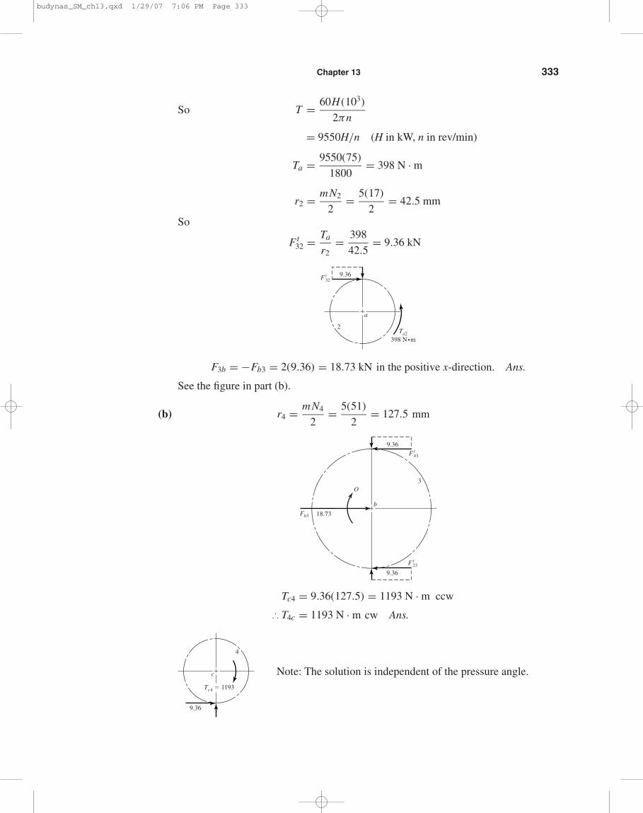
So T = 60H (103)
2πn
= 9550H/n (H in kW, n in rev/min)
Ta = 9550(75)
1800= 398 N · m
r2 = mN2
2= 5(17)
2= 42.5 mm
So
Ft32 = Ta
r2= 398
42.5= 9.36 kN
F3b = −Fb3 = 2(9.36) = 18.73 kN in the positive x-direction. Ans.
See the figure in part (b).
(b) r4 = mN4
2= 5(51)
2= 127.5 mm
Tc4 = 9.36(127.5) = 1193 N · m ccw
∴ T4c = 1193 N · m cw Ans.
Note: The solution is independent of the pressure angle.
9.36
4
c
Tc4 � 1193
b
9.36
O3
F t43
9.36
18.73
F t23
Fb3
9.36
2
a
Ta2
398 N•m
Ft32
budynas_SM_ch13.qxd 1/29/07 7:06 PM Page 333
334 Solutions Manual • Instructor’s Solution Manual to Accompany Mechanical Engineering Design
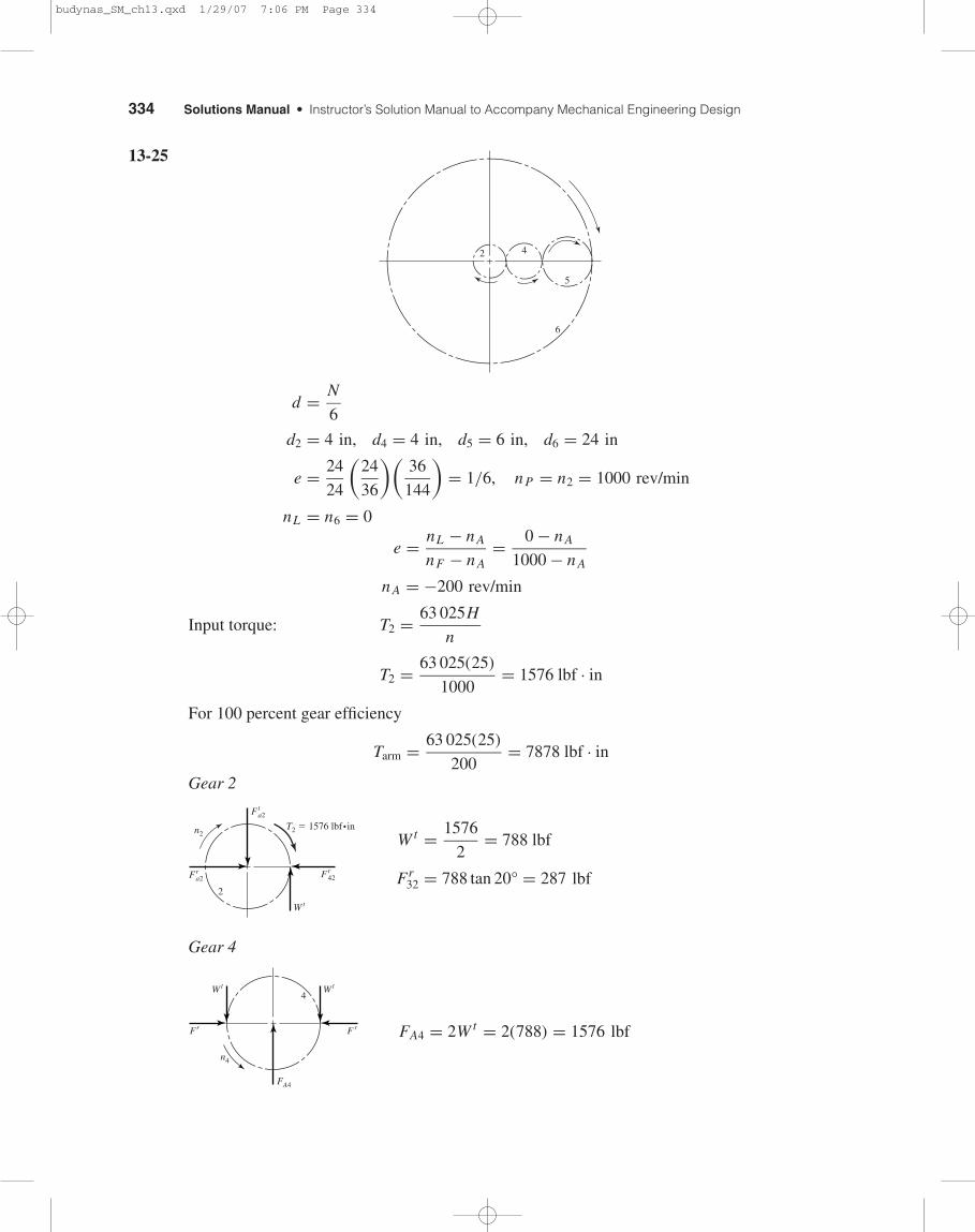
13-25
d = N
6
d2 = 4 in, d4 = 4 in, d5 = 6 in, d6 = 24 in
e = 24
24
(24
36
)(36
144
)= 1/6, nP = n2 = 1000 rev/min
nL = n6 = 0
e = nL − n A
nF − n A= 0 − n A
1000 − n A
n A = −200 rev/min
Input torque: T2 = 63 025H
n
T2 = 63 025(25)
1000= 1576 lbf · in
For 100 percent gear efficiency
Tarm = 63 025(25)
200= 7878 lbf · in
Gear 2
W t = 1576
2= 788 lbf
Fr32 = 788 tan 20° = 287 lbf
Gear 4
FA4 = 2W t = 2(788) = 1576 lbf
4
n4
FA4
WtWt
Fr F r
2
T2 � 1576 lbf • inn2
Fta2
W t
Fra2 Fr
42
2 4
5
6
budynas_SM_ch13.qxd 1/29/07 7:06 PM Page 334
Chapter 13 335
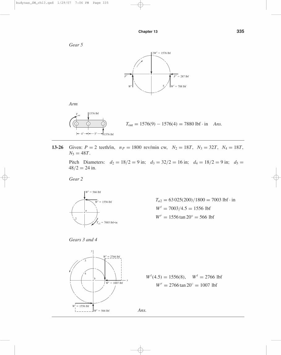
Gear 5
Arm
Tout = 1576(9) − 1576(4) = 7880 lbf · in Ans.
13-26 Given: P = 2 teeth/in, nP = 1800 rev/min cw, N2 = 18T , N3 = 32T , N4 = 18T ,N5 = 48T .
Pitch Diameters: d2 = 18/2 = 9 in; d3 = 32/2 = 16 in; d4 = 18/2 = 9 in; d5 =48/2 = 24 in.
Gear 2
Ta2 = 63 025(200)/1800 = 7003 lbf · in
W t = 7003/4.5 = 1556 lbf
Wr = 1556 tan 20° = 566 lbf
Gears 3 and 4
W t (4.5) = 1556(8), W t = 2766 lbf
Wr = 2766 tan 20◦ = 1007 lbf
Ans.
b
3
4
y
x
Wr � 566 lbf
Wt � 1556 lbf
Wt � 2766 lbf
Wr � 1007 lbf
2
a
W t � 1556 lbf
Wr � 566 lbf
Ta2 � 7003 lbf•in
4" 5"
1576 lbf
1576 lbf
Tout
���
5 Wt � 788 lbf
Fr � 287 lbf
2W t � 1576 lbf
Wt
Fr
budynas_SM_ch13.qxd 1/29/07 7:06 PM Page 335
336 Solutions Manual • Instructor’s Solution Manual to Accompany Mechanical Engineering Design
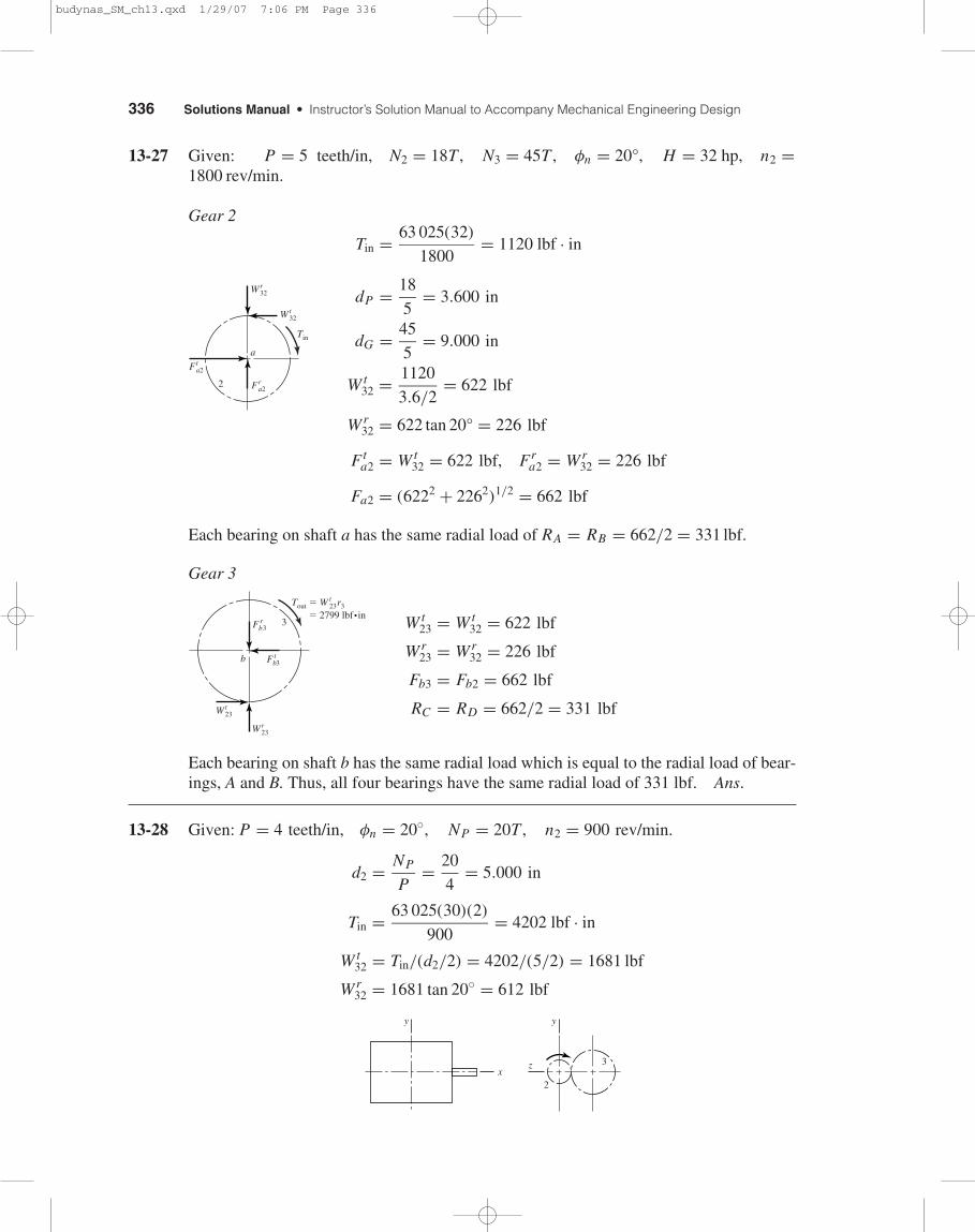
13-27 Given: P = 5 teeth/in, N2 = 18T , N3 = 45T , φn = 20°, H = 32 hp, n2 =1800 rev/min.
Gear 2
Tin = 63 025(32)
1800= 1120 lbf · in
dP = 18
5= 3.600 in
dG = 45
5= 9.000 in
W t32 = 1120
3.6/2= 622 lbf
Wr32 = 622 tan 20° = 226 lbf
Fta2 = W t
32 = 622 lbf, Fra2 = Wr
32 = 226 lbf
Fa2 = (6222 + 2262)1/2 = 662 lbf
Each bearing on shaft a has the same radial load of RA = RB = 662/2 = 331 lbf.
Gear 3
W t23 = W t
32 = 622 lbf
Wr23 = Wr
32 = 226 lbf
Fb3 = Fb2 = 662 lbf
RC = RD = 662/2 = 331 lbf
Each bearing on shaft b has the same radial load which is equal to the radial load of bear-ings, A and B. Thus, all four bearings have the same radial load of 331 lbf. Ans.
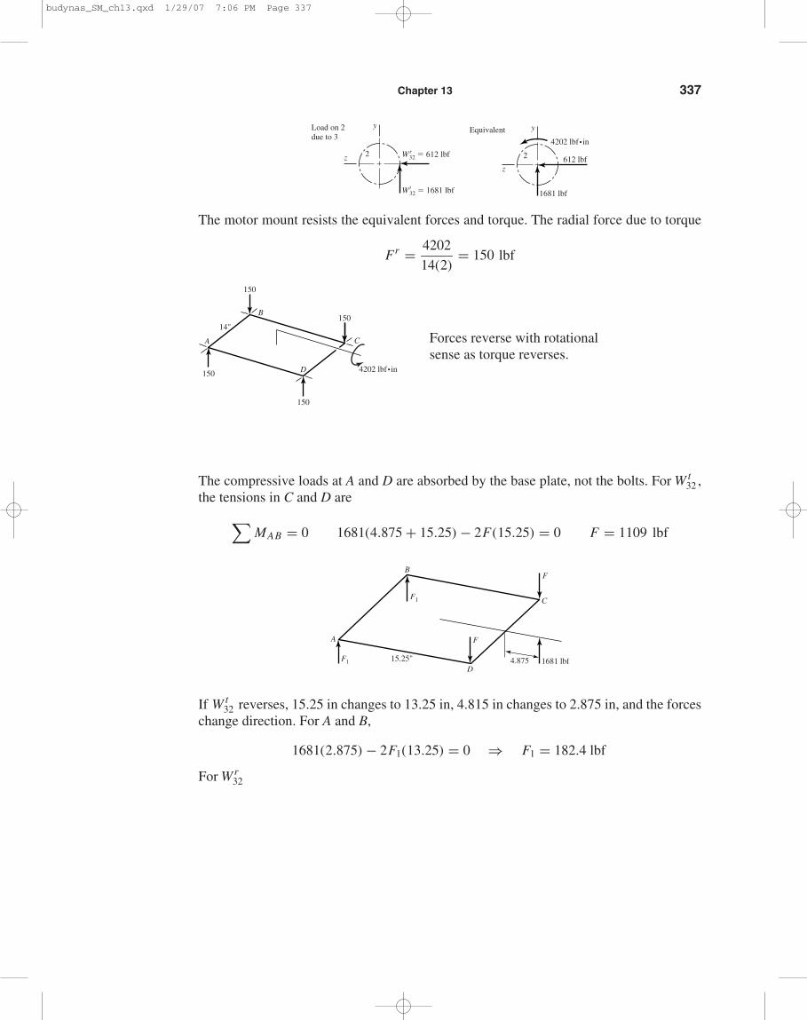
13-28 Given: P = 4 teeth/in, φn = 20◦, NP = 20T , n2 = 900 rev/min.
d2 = NP
P= 20
4= 5.000 in
Tin = 63 025(30)(2)
900= 4202 lbf · in
W t32 = Tin/(d2/2) = 4202/(5/2) = 1681 lbf
Wr32 = 1681 tan 20◦ = 612 lbf
3
2
y
x
y
z
3
Tout � W t23r3
� 2799 lbf•in
b Fbt3
Wt23
Wr23
Fbr3
2
a
Tin
Wt32
Wr32
Fra2
Fta2
budynas_SM_ch13.qxd 1/29/07 7:06 PM Page 336
Chapter 13 337
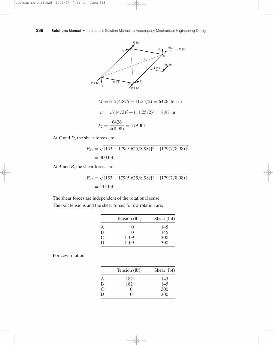
The motor mount resists the equivalent forces and torque. The radial force due to torque
Fr = 4202
14(2)= 150 lbf
Forces reverse with rotational sense as torque reverses.
The compressive loads at A and D are absorbed by the base plate, not the bolts. For W t32 ,
the tensions in C and D are
∑MAB = 0 1681(4.875 + 15.25) − 2F(15.25) = 0 F = 1109 lbf
If W t32 reverses, 15.25 in changes to 13.25 in, 4.815 in changes to 2.875 in, and the forces
change direction. For A and B,
1681(2.875) − 2F1(13.25) = 0 ⇒ F1 = 182.4 lbf
For Wr32
B
C
1681 lbf4.87515.25"
F
F
DF1
F1
A
C
D
A
B
150
14"
150
150
4202 lbf•in150
y
2 612 lbf
4202 lbf•in
1681 lbf
z
Equivalenty
z 2
Wt32 � 1681 lbf
Wr32 � 612 lbf
Load on 2due to 3
budynas_SM_ch13.qxd 1/29/07 7:06 PM Page 337
338 Solutions Manual • Instructor’s Solution Manual to Accompany Mechanical Engineering Design
M = 612(4.875 + 11.25/2) = 6426 lbf · in
a =√
(14/2)2 + (11.25/2)2 = 8.98 in
F2 = 6426
4(8.98)= 179 lbf
At C and D, the shear forces are:
FS1 =√
[153 + 179(5.625/8.98)]2 + [179(7/8.98)]2
= 300 lbf
At A and B, the shear forces are:
FS2 =√
[153 − 179(5.625/8.98)]2 + [179(7/8.98)]2
= 145 lbf
The shear forces are independent of the rotational sense.
The bolt tensions and the shear forces for cw rotation are,
Tension (lbf) Shear (lbf)
A 0 145B 0 145C 1109 300D 1109 300
For ccw rotation,
Tension (lbf) Shear (lbf)
A 182 145B 182 145C 0 300D 0 300
C
aD
153 lbf
153 lbfF2
F2F2
F2
6124 � 153 lbf
4.875
11.25
14612 lbf
153 lbf
budynas_SM_ch13.qxd 1/29/07 7:06 PM Page 338
Chapter 13 339
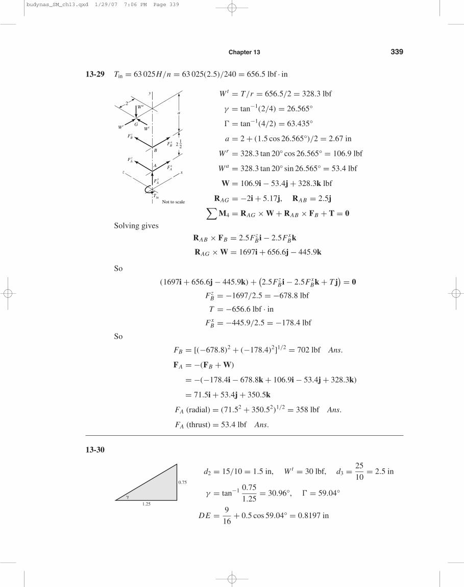
13-29 Tin = 63 025H/n = 63 025(2.5)/240 = 656.5 lbf · in
W t = T/r = 656.5/2 = 328.3 lbf
γ = tan−1(2/4) = 26.565°
� = tan−1(4/2) = 63.435°
a = 2 + (1.5 cos 26.565°)/2 = 2.67 in
Wr = 328.3 tan 20° cos 26.565° = 106.9 lbf
W a = 328.3 tan 20° sin 26.565° = 53.4 lbf
W = 106.9i − 53.4j + 328.3k lbf
RAG = −2i + 5.17j, RAB = 2.5j∑M4 = RAG × W + RAB × FB + T = 0
Solving gives
RAB × FB = 2.5FzB i − 2.5Fx
Bk
RAG × W = 1697i + 656.6j − 445.9k
So
(1697i + 656.6j − 445.9k) + (2.5Fz
B i − 2.5FxBk + T j
) = 0
FzB = −1697/2.5 = −678.8 lbf
T = −656.6 lbf · in
FxB = −445.9/2.5 = −178.4 lbf
So
FB = [(−678.8)2 + (−178.4)2]1/2 = 702 lbf Ans.
FA = −(FB + W)
= −(−178.4i − 678.8k + 106.9i − 53.4j + 328.3k)
= 71.5i + 53.4j + 350.5k
FA (radial) = (71.52 + 350.52)1/2 = 358 lbf Ans.
FA (thrust) = 53.4 lbf Ans.
13-30
d2 = 15/10 = 1.5 in, W t = 30 lbf, d3 = 25
10= 2.5 in
γ = tan−1 0.75
1.25= 30.96°, � = 59.04°
DE = 9
16+ 0.5 cos 59.04° = 0.8197 in
1.25
0.75
�
y
2
212
B
A
GWtWr
Wa
Tin
Not to scale
xz
a
F yA
F zA
F zB
F xA
F xB
budynas_SM_ch13.qxd 1/29/07 7:06 PM Page 339
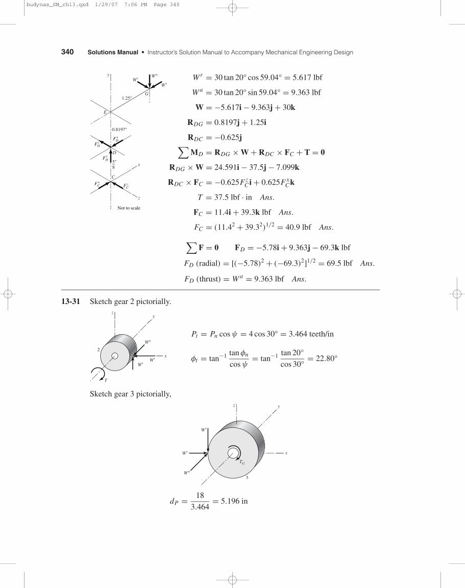
340 Solutions Manual • Instructor’s Solution Manual to Accompany Mechanical Engineering Design
Wr = 30 tan 20° cos 59.04° = 5.617 lbf
W a = 30 tan 20° sin 59.04° = 9.363 lbf
W = −5.617i − 9.363j + 30k
RDG = 0.8197j + 1.25i
RDC = −0.625j∑MD = RDG × W + RDC × FC + T = 0
RDG × W = 24.591i − 37.5j − 7.099k
RDC × FC = −0.625FzC i + 0.625Fx
Ck
T = 37.5 lbf · in Ans.
FC = 11.4i + 39.3k lbf Ans.
FC = (11.42 + 39.32)1/2 = 40.9 lbf Ans.
∑F = 0 FD = −5.78i + 9.363j − 69.3k lbf
FD (radial) = [(−5.78)2 + (−69.3)2]1/2 = 69.5 lbf Ans.
FD (thrust) = W a = 9.363 lbf Ans.
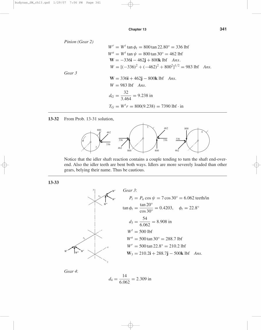
13-31 Sketch gear 2 pictorially.
Pt = Pn cos ψ = 4 cos 30° = 3.464 teeth/in
φt = tan−1 tan φn
cos ψ= tan−1 tan 20°
cos 30°= 22.80°
Sketch gear 3 pictorially,
dP = 18
3.464= 5.196 in
W a
TG
Wr
W t
x
3
yz
Wa
Wr
T
Wt
x
yz
2
Wr
Wa
Wt
z
C
D
E
G
x
y
5"8
0.8197"
1.25"
Not to scale
F xD
F zD
F xC F z
C
F yD
budynas_SM_ch13.qxd 1/29/07 7:06 PM Page 340
Chapter 13 341
Pinion (Gear 2)Wr = W t tan φt = 800 tan 22.80° = 336 lbf
W a = W t tan ψ = 800 tan 30° = 462 lbfW = −336i − 462j + 800k lbf Ans.
W = [(−336)2 + (−462)2 + 8002]1/2 = 983 lbf Ans.Gear 3
W = 336i + 462j − 800k lbf Ans.
W = 983 lbf Ans.
dG = 32
3.464= 9.238 in
TG = W tr = 800(9.238) = 7390 lbf · in
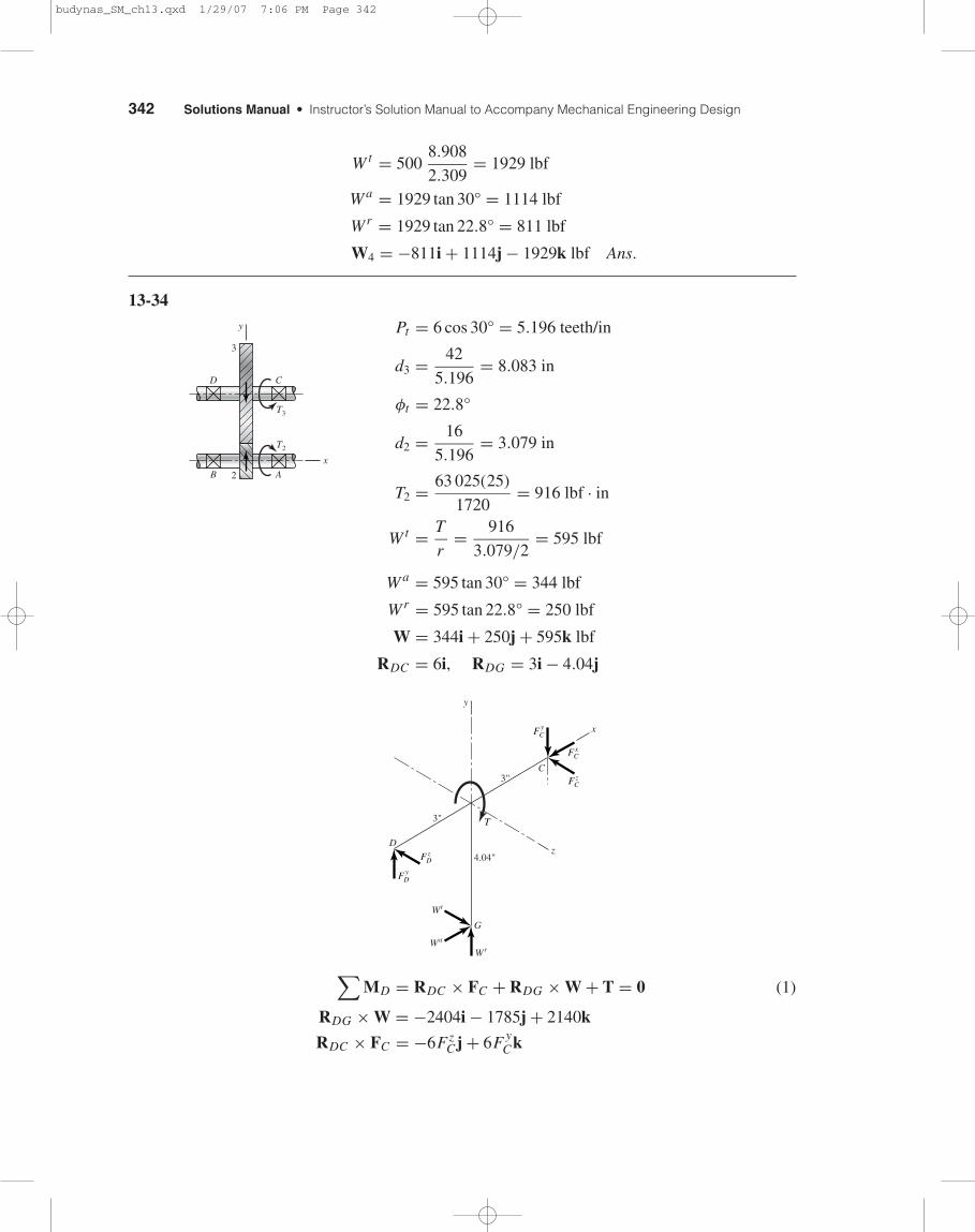
13-32 From Prob. 13-31 solution,
Notice that the idler shaft reaction contains a couple tending to turn the shaft end-over-end. Also the idler teeth are bent both ways. Idlers are more severely loaded than othergears, belying their name. Thus be cautious.
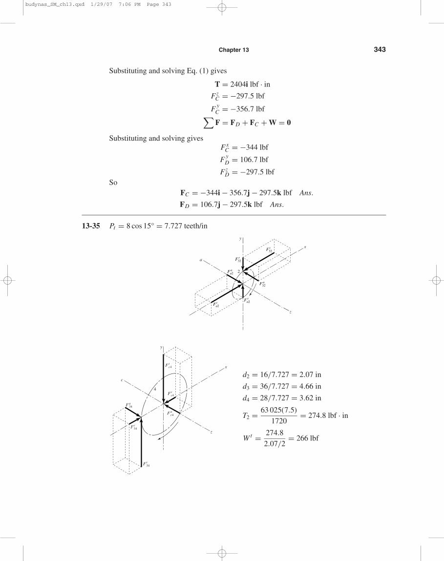
13-33
Gear 3:
Pt = Pn cos ψ = 7 cos 30° = 6.062 teeth/in
tan φt = tan 20°
cos 30°= 0.4203, φt = 22.8°
d3 = 54
6.062= 8.908 in
W t = 500 lbf
W a = 500 tan 30° = 288.7 lbf
Wr = 500 tan 22.8° = 210.2 lbf
W3 = 210.2i + 288.7j − 500k lbf Ans.
Gear 4:
d4 = 14
6.062= 2.309 in
z
y
x
W tWr
Wa
Wt
Wr
Wa
r4
r3
800
336
462
4
800800
336336
4623
462
800
2336
462
budynas_SM_ch13.qxd 1/29/07 7:06 PM Page 341
342 Solutions Manual • Instructor’s Solution Manual to Accompany Mechanical Engineering Design
W t = 5008.908
2.309= 1929 lbf
W a = 1929 tan 30° = 1114 lbf
Wr = 1929 tan 22.8° = 811 lbf
W4 = −811i + 1114j − 1929k lbf Ans.
13-34
Pt = 6 cos 30° = 5.196 teeth/in
d3 = 42
5.196= 8.083 in
φt = 22.8°
d2 = 16
5.196= 3.079 in
T2 = 63 025(25)
1720= 916 lbf · in
W t = T
r= 916
3.079/2= 595 lbf
W a = 595 tan 30° = 344 lbf
Wr = 595 tan 22.8° = 250 lbf
W = 344i + 250j + 595k lbf
RDC = 6i, RDG = 3i − 4.04j
∑MD = RDC × FC + RDG × W + T = 0 (1)
RDG × W = −2404i − 1785j + 2140k
RDC × FC = −6FzC j + 6F y
Ck
G
C
D
x
z
y
WrWa
Wt
4.04"
3"
3"
F yC
F xC
F zC
F z
T
D
F yD
T3
C
AB
D
T2
y
3
2
x
budynas_SM_ch13.qxd 1/29/07 7:06 PM Page 342
Chapter 13 343
Substituting and solving Eq. (1) gives
T = 2404i lbf · in
FzC = −297.5 lbf
F yC = −356.7 lbf∑F = FD + FC + W = 0
Substituting and solving givesFx
C = −344 lbf
F yD = 106.7 lbf
FzD = −297.5 lbf
SoFC = −344i − 356.7j − 297.5k lbf Ans.
FD = 106.7j − 297.5k lbf Ans.
13-35 Pt = 8 cos 15° = 7.727 teeth/in
d2 = 16/7.727 = 2.07 in
d3 = 36/7.727 = 4.66 in
d4 = 28/7.727 = 3.62 in
T2 = 63 025(7.5)
1720= 274.8 lbf · in
W t = 274.8
2.07/2= 266 lbf
y
F tc4
Frc4
F ac4
4
Fa34
Fr34
Ft34
z
x
c
y
2
z
x
a
F aa2
F ta2
F ra2
F a32
F r32
F t32
budynas_SM_ch13.qxd 1/29/07 7:06 PM Page 343
344 Solutions Manual • Instructor’s Solution Manual to Accompany Mechanical Engineering Design
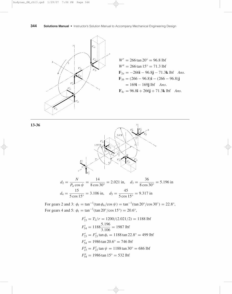
Wr = 266 tan 20° = 96.8 lbf
W a = 266 tan 15° = 71.3 lbf
F2a = −266i − 96.8j − 71.3k lbf Ans.
F3b = (266 − 96.8)i − (266 − 96.8)j
= 169i − 169j lbf Ans.
F4c = 96.8i + 266j + 71.3k lbf Ans.
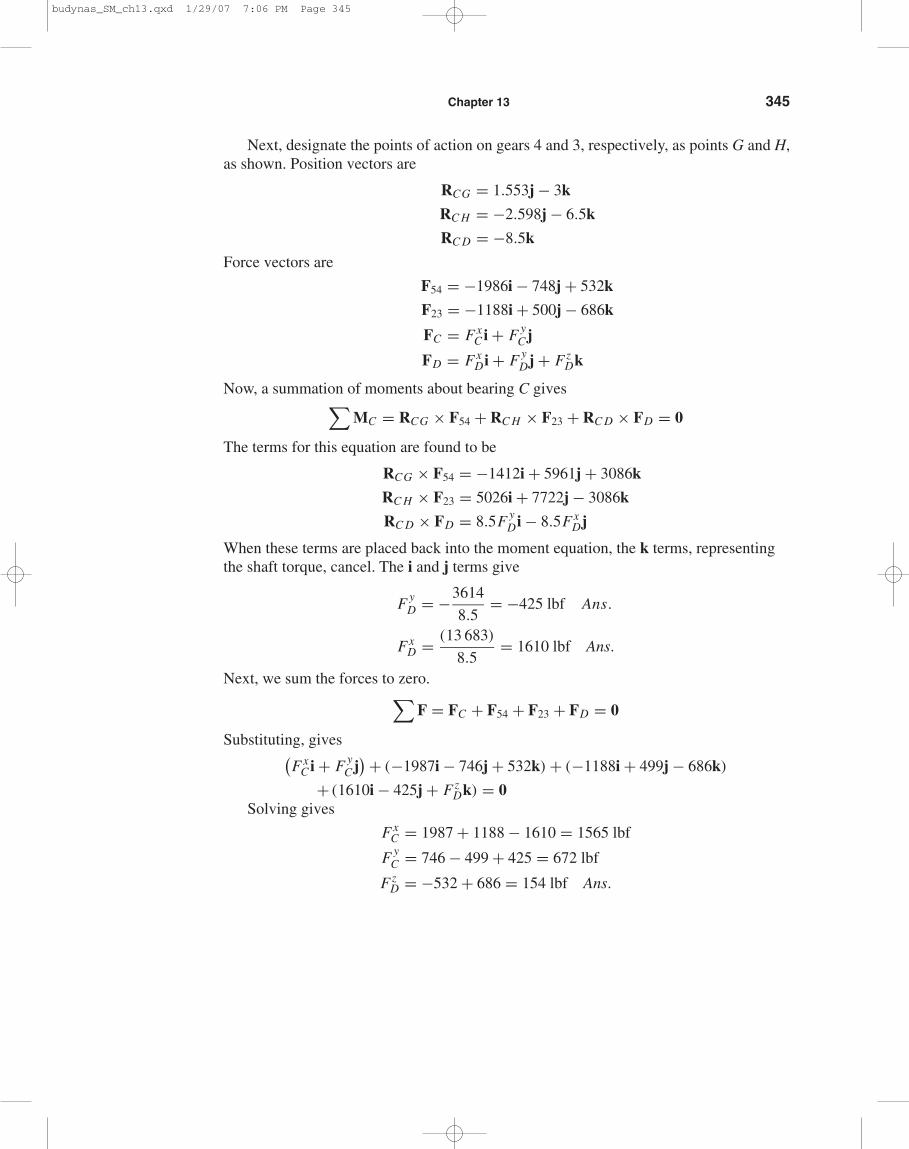
13-36
d2 = N
Pn cos ψ= 14
8 cos 30°= 2.021 in, d3 = 36
8 cos 30°= 5.196 in
d4 = 15
5 cos 15°= 3.106 in, d5 = 45
5 cos 15°= 9.317 in
For gears 2 and 3: φt = tan−1(tan φn/cos ψ) = tan−1(tan 20°/cos 30◦) = 22.8°,
For gears 4 and 5: φt = tan−1(tan 20°/cos 15°) = 20.6°,
Ft23 = T2/r = 1200/(2.021/2) = 1188 lbf
Ft54 = 1188
5.196
3.106= 1987 lbf
Fr23 = Ft
23 tan φt = 1188 tan 22.8° = 499 lbf
Fr54 = 1986 tan 20.6° = 746 lbf
Fa23 = Ft
23 tan ψ = 1188 tan 30° = 686 lbf
Fa54 = 1986 tan 15° = 532 lbf
C
x
y
z
b
F t23
Fr23
Fa23
Ft54
Fa54
Fr54
D
G
H
3"
2"
3
2.6"R
1.55"R
4
31"2
F yDF x
D
F xC
F yC
F zD
y
Fr43
Fxb3
Fyb3
F a23
F r23
Ft23
F t43
F a43
3
Fb3
z
x
b
budynas_SM_ch13.qxd 1/29/07 7:06 PM Page 344
Chapter 13 345
Next, designate the points of action on gears 4 and 3, respectively, as points G and H,as shown. Position vectors are
RCG = 1.553j − 3k
RC H = −2.598j − 6.5k
RC D = −8.5k
Force vectors are
F54 = −1986i − 748j + 532k
F23 = −1188i + 500j − 686k
FC = FxC i + F y
C j
FD = FxDi + F y
Dj + FzDk
Now, a summation of moments about bearing C gives∑MC = RCG × F54 + RC H × F23 + RC D × FD = 0
The terms for this equation are found to be
RCG × F54 = −1412i + 5961j + 3086k
RC H × F23 = 5026i + 7722j − 3086k
RC D × FD = 8.5F yDi − 8.5Fx
Dj
When these terms are placed back into the moment equation, the k terms, representingthe shaft torque, cancel. The i and j terms give
F yD = −3614
8.5= −425 lbf Ans.
FxD = (13 683)
8.5= 1610 lbf Ans.
Next, we sum the forces to zero.∑F = FC + F54 + F23 + FD = 0
Substituting, gives(Fx
C i + F yC j
) + (−1987i − 746j + 532k) + (−1188i + 499j − 686k)
+ (1610i − 425j + FzDk) = 0
Solving gives
FxC = 1987 + 1188 − 1610 = 1565 lbf
F yC = 746 − 499 + 425 = 672 lbf
FzD = −532 + 686 = 154 lbf Ans.
budynas_SM_ch13.qxd 1/29/07 7:06 PM Page 345
346 Solutions Manual • Instructor’s Solution Manual to Accompany Mechanical Engineering Design
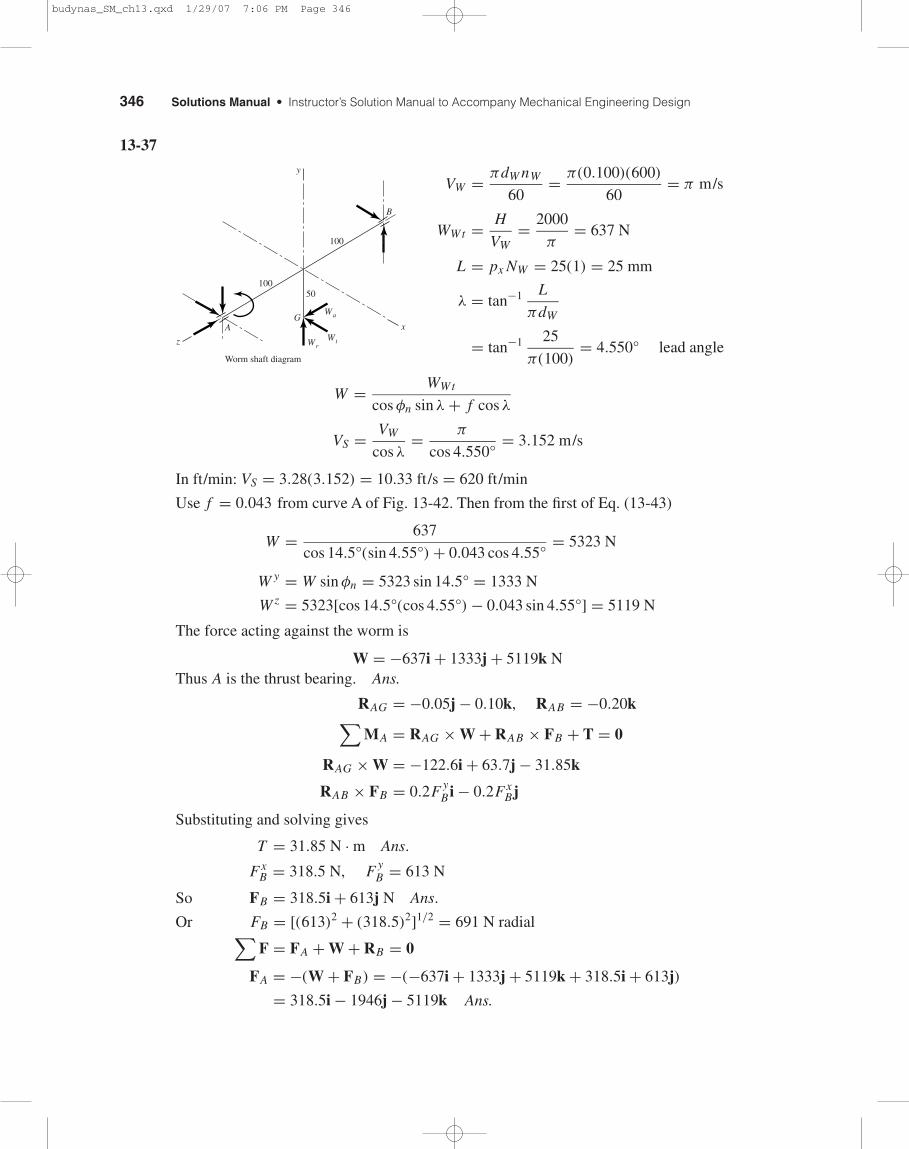
13-37
VW = πdW nW
60= π(0.100)(600)
60= π m/s
WWt = H
VW= 2000
π= 637 N
L = px NW = 25(1) = 25 mm
λ = tan−1 L
πdW
= tan−1 25
π(100)= 4.550° lead angle
W = WWt
cos φn sin λ + f cos λ
VS = VW
cos λ= π
cos 4.550°= 3.152 m/s
In ft/min: VS = 3.28(3.152) = 10.33 ft/s = 620 ft/min
Use f = 0.043 from curve A of Fig. 13-42. Then from the first of Eq. (13-43)
W = 637
cos 14.5°(sin 4.55°) + 0.043 cos 4.55°= 5323 N
W y = W sin φn = 5323 sin 14.5° = 1333 N
W z = 5323[cos 14.5°(cos 4.55°) − 0.043 sin 4.55°] = 5119 N
The force acting against the worm is
W = −637i + 1333j + 5119k NThus A is the thrust bearing. Ans.
RAG = −0.05j − 0.10k, RAB = −0.20k∑MA = RAG × W + RAB × FB + T = 0
RAG × W = −122.6i + 63.7j − 31.85k
RAB × FB = 0.2F yB i − 0.2Fx
Bj
Substituting and solving gives
T = 31.85 N · m Ans.
FxB = 318.5 N, F y
B = 613 N
So FB = 318.5i + 613j N Ans.
Or FB = [(613)2 + (318.5)2]1/2 = 691 N radial∑F = FA + W + RB = 0
FA = −(W + FB) = −(−637i + 1333j + 5119k + 318.5i + 613j)
= 318.5i − 1946j − 5119k Ans.
B
GA x
y
z
Worm shaft diagram
100
100
WrWt
Wa
50
budynas_SM_ch13.qxd 1/29/07 7:06 PM Page 346
Chapter 13 347
Radial FrA = 318.5i − 1946j N,
FrA = [(318.5)2 + (−1946)2]1/2 = 1972 N
Thrust FaA = −5119 N
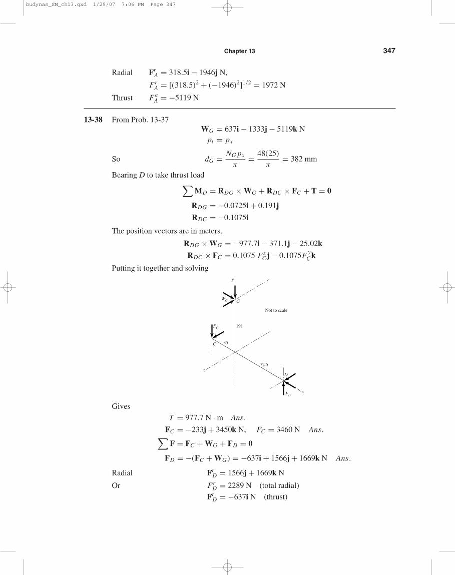
13-38 From Prob. 13-37WG = 637i − 1333j − 5119k N
pt = px
So dG = NG px
π= 48(25)
π= 382 mm
Bearing D to take thrust load∑MD = RDG × WG + RDC × FC + T = 0
RDG = −0.0725i + 0.191j
RDC = −0.1075i
The position vectors are in meters.
RDG × WG = −977.7i − 371.1j − 25.02k
RDC × FC = 0.1075 FzC j − 0.1075F y
Ck
Putting it together and solving
Gives
T = 977.7 N · m Ans.
FC = −233j + 3450k N, FC = 3460 N Ans.∑F = FC + WG + FD = 0
FD = −(FC + WG) = −637i + 1566j + 1669k N Ans.
Radial FrD = 1566j + 1669k N
Or FrD = 2289 N (total radial)
FtD = −637i N (thrust)
G
x
y
z
FD
FC
WG
D
C
72.5
191
35
Not to scale
budynas_SM_ch13.qxd 1/29/07 7:06 PM Page 347
348 Solutions Manual • Instructor’s Solution Manual to Accompany Mechanical Engineering Design
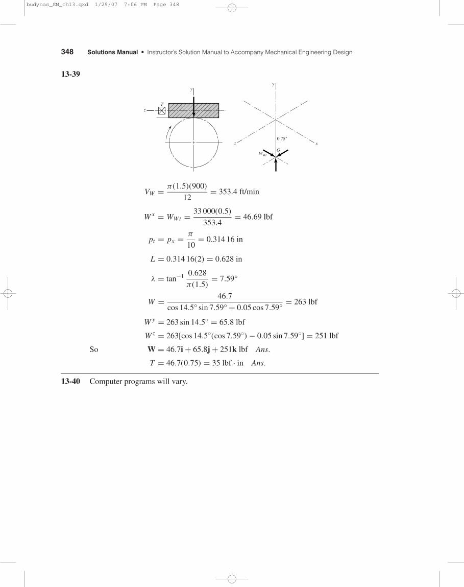
13-39
VW = π(1.5)(900)
12= 353.4 ft/min
W x = WWt = 33 000(0.5)
353.4= 46.69 lbf
pt = px = π
10= 0.314 16 in
L = 0.314 16(2) = 0.628 in
λ = tan−1 0.628
π(1.5)= 7.59°
W = 46.7
cos 14.5° sin 7.59° + 0.05 cos 7.59°= 263 lbf
W y = 263 sin 14.5◦ = 65.8 lbf
W z = 263[cos 14.5◦(cos 7.59◦) − 0.05 sin 7.59◦] = 251 lbf
So W = 46.7i + 65.8j + 251k lbf Ans.
T = 46.7(0.75) = 35 lbf · in Ans.
13-40 Computer programs will vary.
x
y
z
WWtG
0.75"
T
y
z
budynas_SM_ch13.qxd 1/29/07 7:06 PM Page 348