ΛΦ45/55 series
188
STRUCTURE ' 200436 DW23259602 0 1 2 3 4 5 ΛΦ45/55 series 6 Structure TECHNICAL DATA DIAGNOSTICS BRAKE DIAGRAMS FOR THE FULLY PNEUMATIC BRAKE SYSTEM OPERATION OF BRAKE COMPONENTS BRAKE SYSTEM AND COMPONENTS BRAKING PERFORMANCE AND BRAKE EQUALISATION https://www.truck-manuals.net/
Transcript of ΛΦ45/55 series
STRUCTURE
© 200436 DW23259602
0
1
2
3
4
5
ΛΦ45/55 series6
Structure TECHNICAL DATA
DIAGNOSTICS
BRAKE DIAGRAMS FOR THE FULLY PNEUMATIC BRAKE SYSTEM
OPERATION OF BRAKE COMPONENTS
BRAKE SYSTEM AND COMPONENTS
BRAKING PERFORMANCE AND BRAKE EQUALISATION
https://www.truck-manuals.net/

https://www.truck-manuals.net/
© 200436 1
ContentsTECHNICAL DATA
ΛΦ45/55 series6
00 Technical dataCONTENTS
Page Date
1. BRAKE SYSTEM AND COMPONENTS. . . . . . . . . . . . . . . . . . . . . . . . . . . . . . . 1-1 . . . . . 2004361.1 General . . . . . . . . . . . . . . . . . . . . . . . . . . . . . . . . . . . . . . . . . . . . . . . . . . . 1-1 . . . . . 2004361.2 Tightening torques. . . . . . . . . . . . . . . . . . . . . . . . . . . . . . . . . . . . . . . . . . . 1-12 . . . . 2004361.3 Lubricants . . . . . . . . . . . . . . . . . . . . . . . . . . . . . . . . . . . . . . . . . . . . . . . . 1-16 . . . . 200436
https://www.truck-manuals.net/

TECHNICAL DATA
2 © 200436
Contents
0
ΛΦ45/55 series6
https://www.truck-manuals.net/
© 200436 1-1
Brake system and componentsTECHNICAL DATA
ΛΦ45/55 series6
01. BRAKE SYSTEM AND COMPONENTS1.1 GENERAL
Coding of componentsAll components have been provided with number codes.
Structure of the codeFirst digitOften used:
Little used:
Where one connection performs several functions, additional 1stdigits will be allocated. These are separated by a hyphen.
Second digitIf there are several connections with the same function, a 2nd digit will be added immediately after the 1st one.
Application example: empty/load relay valve
Meaning:
COMPRESSORKnorr model
1 Energy supply (pressure)2 Energy discharge (outgoing command)3 Bleed4 Control connection (incoming command)
0 Suction connection5 Free6 Free7 Anti-freeze connection8 Lubricating oil connection9 Coolant connection
1 Air compressor energy supply2 Energy discharge (command) to the next
component41 Control connection (incoming)42 Second control connection (incoming)
Type: LK3839Version: 1-cylinder, liquid-cooled
https://www.truck-manuals.net/
TECHNICAL DATA
1-2 © 200436
Brake system and components
0
ΛΦ45/55 series6
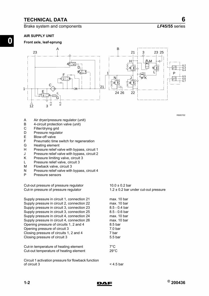
AIR SUPPLY UNIT
Front axle, leaf-sprung
24
21
1F
D
N J K
L
MH
P
3
A
E
C
G
1
12
26 22
2123 3 23 25
P U6.26.36.4
6.1
6.2
P U6.56.66.7
B
R600702
0
A Air dryer/pressure regulator (unit)B 4-circuit protection valve (unit)C Filter/drying gridD Pressure regulatorE Blow-off valveF Pneumatic time switch for regenerationG Heating elementH Pressure relief valve with bypass, circuit 1J Pressure relief valve with bypass, circuit 2K Pressure limiting valve, circuit 3L Pressure relief valve, circuit 3M Flowback valve, circuit 3N Pressure relief valve with bypass, circuit 4P Pressure sensors
Cut-out pressure of pressure regulator 10.0 ≥ 0.2 barCut-in pressure of pressure regulator 1.2 ≥ 0.2 bar under cut-out pressure
Supply pressure in circuit 1, connection 21 max. 10 barSupply pressure in circuit 2, connection 22 max. 10 barSupply pressure in circuit 3, connection 23 8.5 - 0.4 barSupply pressure in circuit 3, connection 25 8.5 - 0.6 barSupply pressure in circuit 4, connection 24 max. 10 barSupply pressure in circuit 4, connection 26 max. 10 barOpening pressure of circuits 1, 2 and 4 8.5 barOpening pressure of circuit 3 7.0 barClosing pressure of circuits 1, 2 and 4 7 barClosing pressure of circuit 3 5.5 bar
Cut-in temperature of heating element 7CCut-out temperature of heating element 29C
Circuit 1 activation pressure for flowback function of circuit 3 < 4.5 bar
https://www.truck-manuals.net/
© 200436 1-3
Brake system and componentsTECHNICAL DATA
ΛΦ45/55 series6
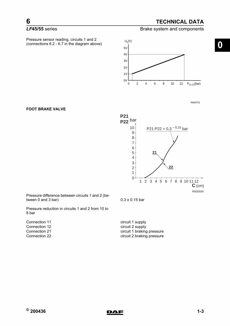
0Pressure sensor reading, circuits 1 and 2(connections 6.2 - 6.7 in the diagram above)
FOOT BRAKE VALVE
Pressure reduction in circuits 1 and 2 from 10 to 8 bar
1V
0V
2V
3V
4V
5V
120 2 4 6 8 10 P21.22(bar)
Ua(V)
R600701
456789
10
barP21P22
321
1 2 3 4 5 6 7 8 9 10 11 12C (cm)
0
P21-P22 = 0,3 – 0,15 bar
21
22
R600594
Pressure difference between circuits 1 and 2 (be-tween 0 and 3 bar) 0.3 ≥ 0.15 bar
Connection 11 circuit 1 supplyConnection 12 circuit 2 supplyConnection 21 circuit 1 braking pressureConnection 22 circuit 2 braking pressure
https://www.truck-manuals.net/
TECHNICAL DATA
1-4 © 200436
Brake system and components
0
ΛΦ45/55 series6
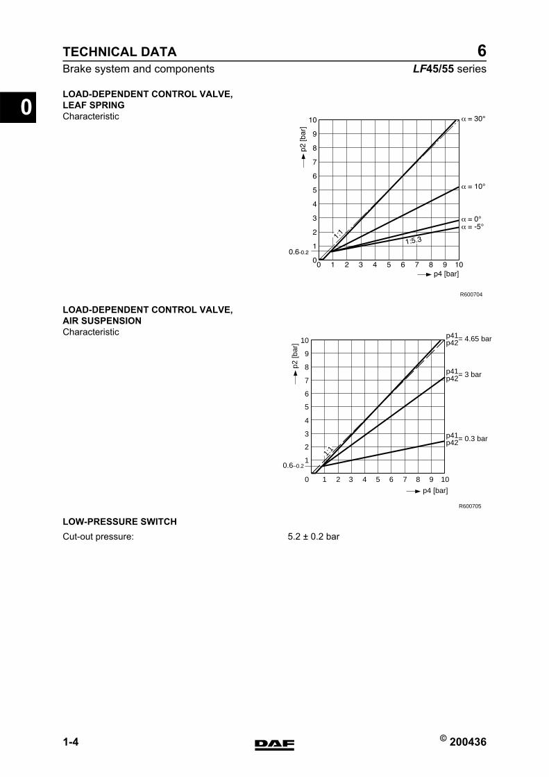
LOAD-DEPENDENT CONTROL VALVE, LEAF SPRINGCharacteristic
LOAD-DEPENDENT CONTROL VALVE, AIR SUSPENSIONCharacteristic
LOW-PRESSURE SWITCH
R600704
10
0.6–0.21
2
3
4
5
6
7
8
9
10
2 3 4 5 6 7 8 9 10
R600705
p41p42= 4.65 bar
p41p42= 3 bar
p41p42= 0.3 bar
p4 [bar]
p2 [b
ar]
1:1
Cut-out pressure: 5.2 ≥ 0.2 bar
https://www.truck-manuals.net/
© 200436 1-5
Brake system and componentsTECHNICAL DATA
ΛΦ45/55 series6
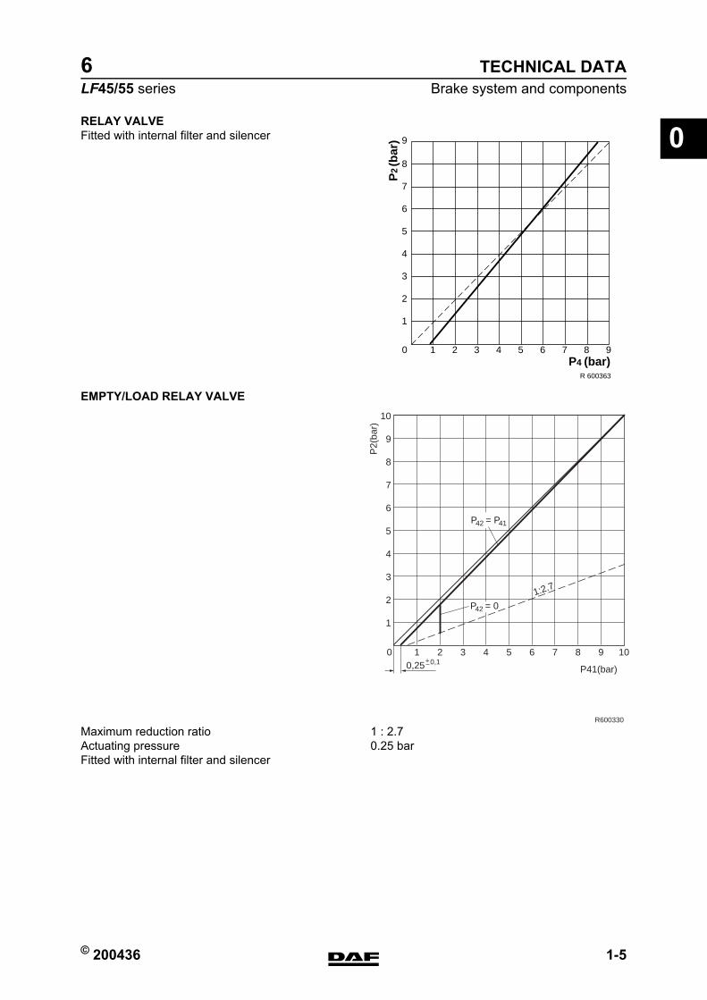
0RELAY VALVEFitted with internal filter and silencer
EMPTY/LOAD RELAY VALVE
10 2 3 4 5 6 7 8 9
1
2
3
4
5
6
7
8
9
P2
(bar
)
P4 (bar)R 600363
0
1
2
3
4
5
6
7
8
9
10
10,25 P41(bar)
P2(
bar)
R600330
2 3 4 5 6 7 8 9 100,1+
P42 = P41
P42 = 01:2.7
Maximum reduction ratio 1 : 2.7Actuating pressure 0.25 barFitted with internal filter and silencer
https://www.truck-manuals.net/

TECHNICAL DATA
1-6 © 200436
Brake system and components
0
ΛΦ45/55 series6
ABS VALVE
Electrical connections
ASR solenoid valve
TRAILER VEHICLE CONTROL VALVEKnorr model
Advance
Resistance of magnet coil 15 ≥ 5 ohm at 25C
1
2 3
2 1
1 2 3
3
R600370
1. Bleed magnet coil2. Earth3. Aerate magnet coil
13
2
R600484
1. Supply2. Port, two-way valve3. Bleed
Type: AC 597BA
Input pressure 3 barOutput pressure 3.2 bar(equals 0.2 bar advance = factory setting)
https://www.truck-manuals.net/

© 200436 1-7
Brake system and componentsTECHNICAL DATA
ΛΦ45/55 series6
0Advance adjustmentAdjusting screw (Allen type, 6 mm)Clockwise increases the advanceAnti-clockwise decreases the advance
Knorr model
Advance
Advance adjustmentAdjusting screw (Allen type, 6 mm)Clockwise increases the advanceAnti-clockwise decreases the advance
PARKING BRAKE VALVE WITH TRAILER VEHICLE CONNECTION
Wabco model
Type: AC 597C
Input pressure 3 barOutput pressure 3.5 bar(equals 0.5 bar advance = factory setting)
Type: 961 723 134 0Max. output pressure in driving position approx. 8 bar
https://www.truck-manuals.net/
TECHNICAL DATA
1-8 © 200436
Brake system and components
0
ΛΦ45/55 series6
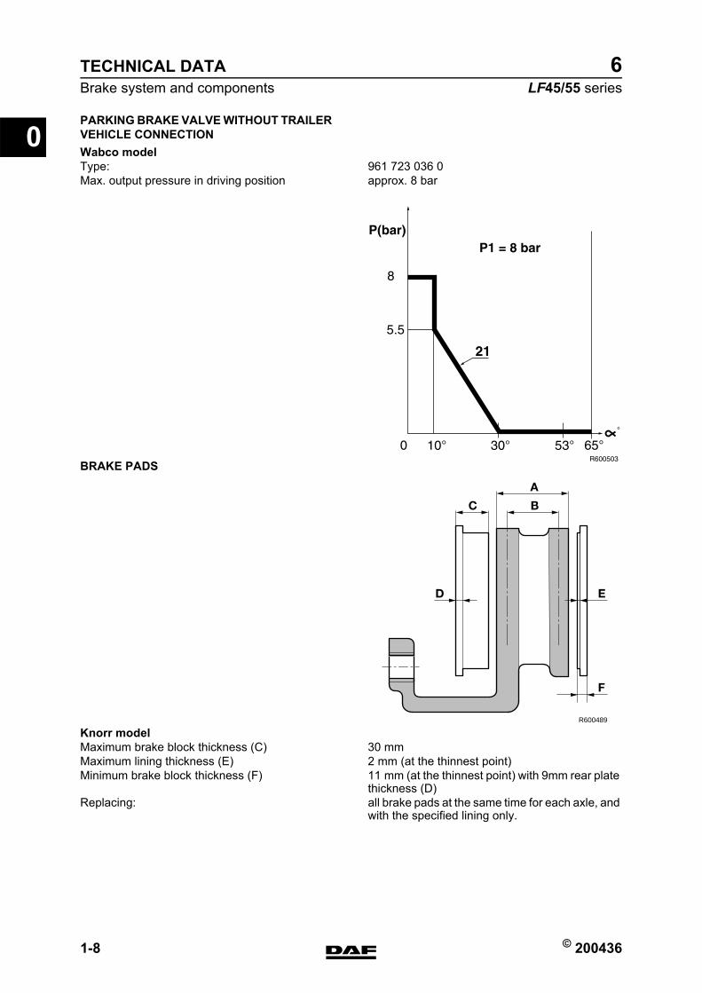
PARKING BRAKE VALVE WITHOUT TRAILER VEHICLE CONNECTIONWabco model
BRAKE PADS
Knorr model
Type: 961 723 036 0Max. output pressure in driving position approx. 8 bar
R600489
A
B
F
ED
C
Maximum brake block thickness (C) 30 mmMaximum lining thickness (E) 2 mm (at the thinnest point)Minimum brake block thickness (F) 11 mm (at the thinnest point) with 9mm rear plate
thickness (D)Replacing: all brake pads at the same time for each axle, and
with the specified lining only.
https://www.truck-manuals.net/
© 200436 1-9
Brake system and componentsTECHNICAL DATA
ΛΦ45/55 series6
0Wabco PAN 17 version:
Wabco PAN 19-1+ and PAN 19-2 versions:
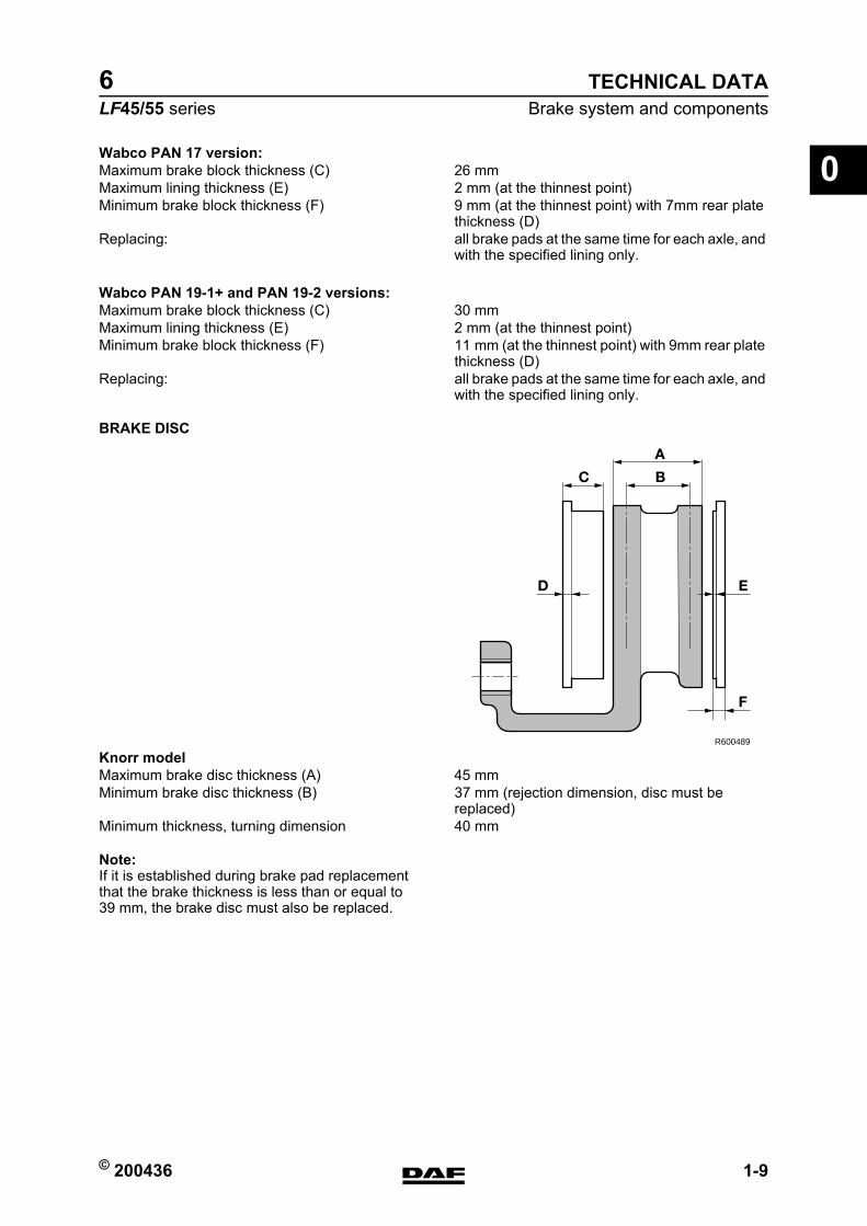
BRAKE DISC
Knorr model
Note:If it is established during brake pad replacement that the brake thickness is less than or equal to 39 mm, the brake disc must also be replaced.
Maximum brake block thickness (C) 26 mmMaximum lining thickness (E) 2 mm (at the thinnest point)Minimum brake block thickness (F) 9 mm (at the thinnest point) with 7mm rear plate
thickness (D)Replacing: all brake pads at the same time for each axle, and
with the specified lining only.
Maximum brake block thickness (C) 30 mmMaximum lining thickness (E) 2 mm (at the thinnest point)Minimum brake block thickness (F) 11 mm (at the thinnest point) with 9mm rear plate
thickness (D)Replacing: all brake pads at the same time for each axle, and
with the specified lining only.
R600489
A
B
F
ED
C
Maximum brake disc thickness (A) 45 mmMinimum brake disc thickness (B) 37 mm (rejection dimension, disc must be
replaced)Minimum thickness, turning dimension 40 mm
https://www.truck-manuals.net/
TECHNICAL DATA
1-10 © 200436
Brake system and components
0
ΛΦ45/55 series6
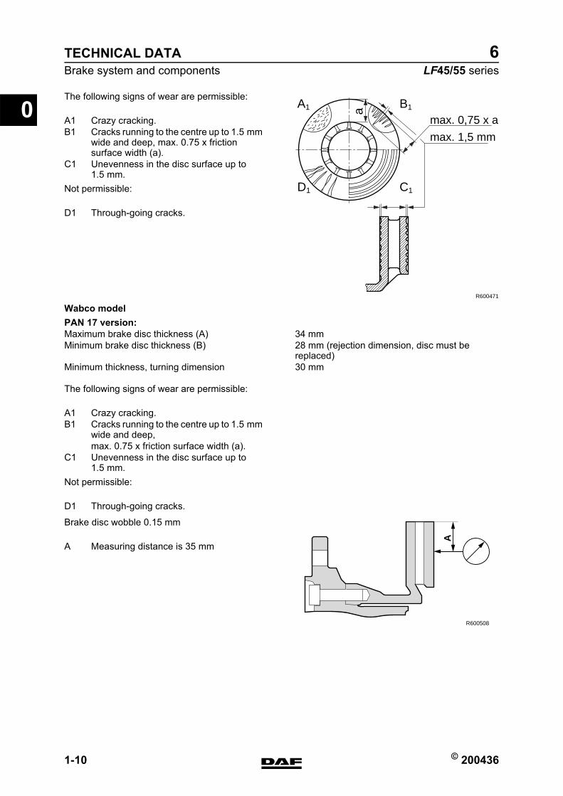
The following signs of wear are permissible:
Not permissible:
Wabco modelPAN 17 version:
The following signs of wear are permissible:
Not permissible:
Brake disc wobble 0.15 mm
max. 0,75 x a
max. 1,5 mm
R600471
A1 B1
D1 C1
a
A1 Crazy cracking.B1 Cracks running to the centre up to 1.5 mm
wide and deep, max. 0.75 x friction surface width (a).
C1 Unevenness in the disc surface up to 1.5 mm.
D1 Through-going cracks.
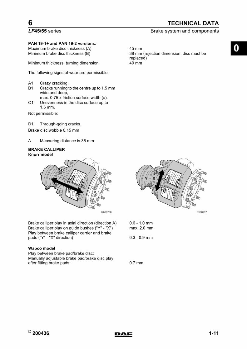
Maximum brake disc thickness (A) 34 mmMinimum brake disc thickness (B) 28 mm (rejection dimension, disc must be
replaced)Minimum thickness, turning dimension 30 mm
A1 Crazy cracking.B1 Cracks running to the centre up to 1.5 mm
wide and deep,max. 0.75 x friction surface width (a).
C1 Unevenness in the disc surface up to 1.5 mm.
D1 Through-going cracks.
A
R600508
A Measuring distance is 35 mm
https://www.truck-manuals.net/
© 200436 1-11
Brake system and componentsTECHNICAL DATA
ΛΦ45/55 series6
0PAN 19-1+ and PAN 19-2 versions:
The following signs of wear are permissible:
Not permissible:
Brake disc wobble 0.15 mm
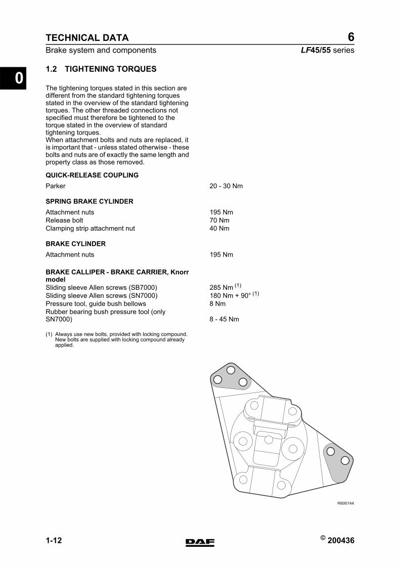
BRAKE CALLIPERKnorr model
Wabco model
Maximum brake disc thickness (A) 45 mmMinimum brake disc thickness (B) 38 mm (rejection dimension, disc must be
replaced)Minimum thickness, turning dimension 40 mm
A1 Crazy cracking.B1 Cracks running to the centre up to 1.5 mm
wide and deep,max. 0.75 x friction surface width (a).
C1 Unevenness in the disc surface up to 1.5 mm.
D1 Through-going cracks.
A Measuring distance is 35 mm
R600708
A
R600712
Y - X
Brake calliper play in axial direction (direction A) 0.6 - 1.0 mmBrake calliper play on guide bushes ("Y" - "X") max. 2.0 mmPlay between brake calliper carrier and brake pads ("Y" - "X" direction) 0.3 - 0.9 mm
Play between brake pad/brake disc:Manually adjustable brake pad/brake disc play after fitting brake pads: 0.7 mm
https://www.truck-manuals.net/
TECHNICAL DATA
1-12 © 200436
Brake system and components
0
ΛΦ45/55 series6
1.2 TIGHTENING TORQUES
The tightening torques stated in this section are different from the standard tightening torques stated in the overview of the standard tightening torques. The other threaded connections not specified must therefore be tightened to the torque stated in the overview of standard tightening torques.When attachment bolts and nuts are replaced, it is important that - unless stated otherwise - these bolts and nuts are of exactly the same length and property class as those removed.
QUICK-RELEASE COUPLING
SPRING BRAKE CYLINDER
BRAKE CYLINDER
BRAKE CALLIPER - BRAKE CARRIER, Knorr model
(1) Always use new bolts, provided with locking compound. New bolts are supplied with locking compound already applied.
Parker 20 - 30 Nm
Attachment nuts 195 NmRelease bolt 70 NmClamping strip attachment nut 40 Nm
Attachment nuts 195 Nm
Sliding sleeve Allen screws (SB7000) 285 Nm (1)
Sliding sleeve Allen screws (SN7000) 180 Nm + 90 (1)
Pressure tool, guide bush bellows 8 NmRubber bearing bush pressure tool (only SN7000) 8 - 45 Nm
R600744
https://www.truck-manuals.net/
© 200436 1-13
Brake system and componentsTECHNICAL DATA
ΛΦ45/55 series6
0(1) From production date 2003-37 there is one fitted bolt and
flange bolts are also fitted.The fitted bolt must be fitted at the position marked by a small hole.
(2) In the case of versions with Knorr disc brakes, the attachment of the brake calliper against the stub axle changed starting from production week 2002-25. Five bolts are now used instead of six bolts. There is still a hole for the 6th bolt on the brake carrier, but there is no hole on the stub axle.
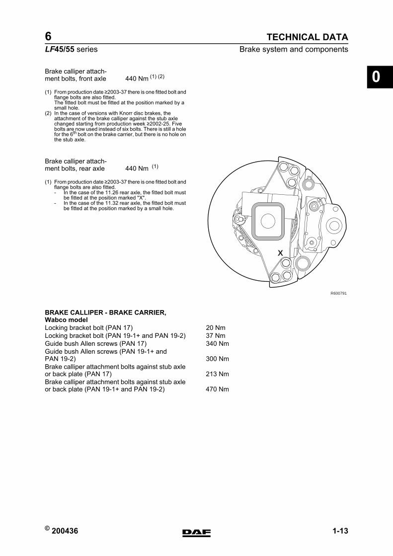
(1) From production date 2003-37 there is one fitted bolt and flange bolts are also fitted.- In the case of the 11.26 rear axle, the fitted bolt must
be fitted at the position marked "X".- In the case of the 11.32 rear axle, the fitted bolt must
be fitted at the position marked by a small hole.
BRAKE CALLIPER - BRAKE CARRIER, Wabco model
Brake calliper attach-ment bolts, front axle 440 Nm (1) (2)
X
R600791
Brake calliper attach-ment bolts, rear axle 440 Nm (1)
Locking bracket bolt (PAN 17) 20 NmLocking bracket bolt (PAN 19-1+ and PAN 19-2) 37 NmGuide bush Allen screws (PAN 17) 340 NmGuide bush Allen screws (PAN 19-1+ and PAN 19-2) 300 NmBrake calliper attachment bolts against stub axle or back plate (PAN 17) 213 NmBrake calliper attachment bolts against stub axle or back plate (PAN 19-1+ and PAN 19-2) 470 Nm
https://www.truck-manuals.net/
TECHNICAL DATA
1-14 © 200436
Brake system and components
0
ΛΦ45/55 series6
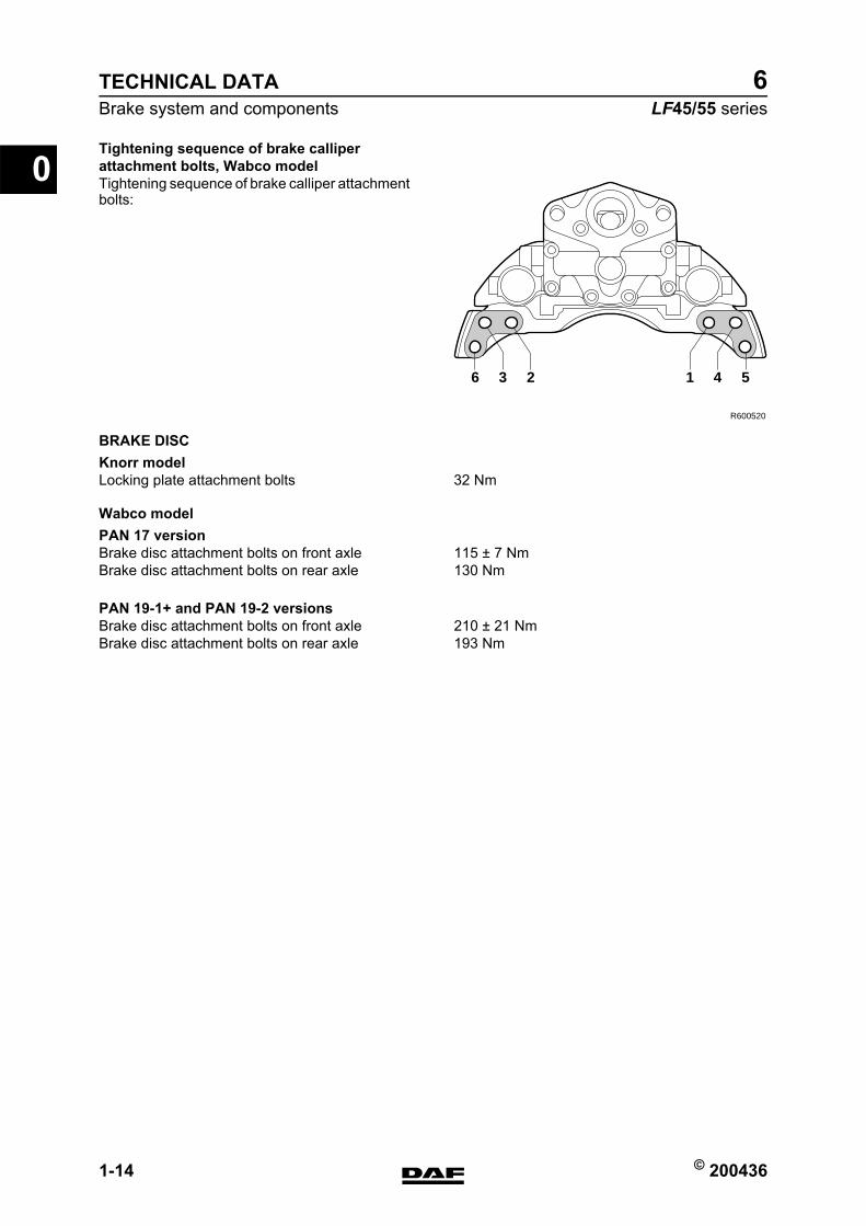
Tightening sequence of brake calliper attachment bolts, Wabco modelTightening sequence of brake calliper attachment bolts:
BRAKE DISCKnorr model
Wabco modelPAN 17 version
PAN 19-1+ and PAN 19-2 versions
R600520
6 23 1 54
Locking plate attachment bolts 32 Nm
Brake disc attachment bolts on front axle 115 ≥ 7 NmBrake disc attachment bolts on rear axle 130 Nm
Brake disc attachment bolts on front axle 210 ≥ 21 NmBrake disc attachment bolts on rear axle 193 Nm
https://www.truck-manuals.net/
© 200436 1-15
Brake system and componentsTECHNICAL DATA
ΛΦ45/55 series6
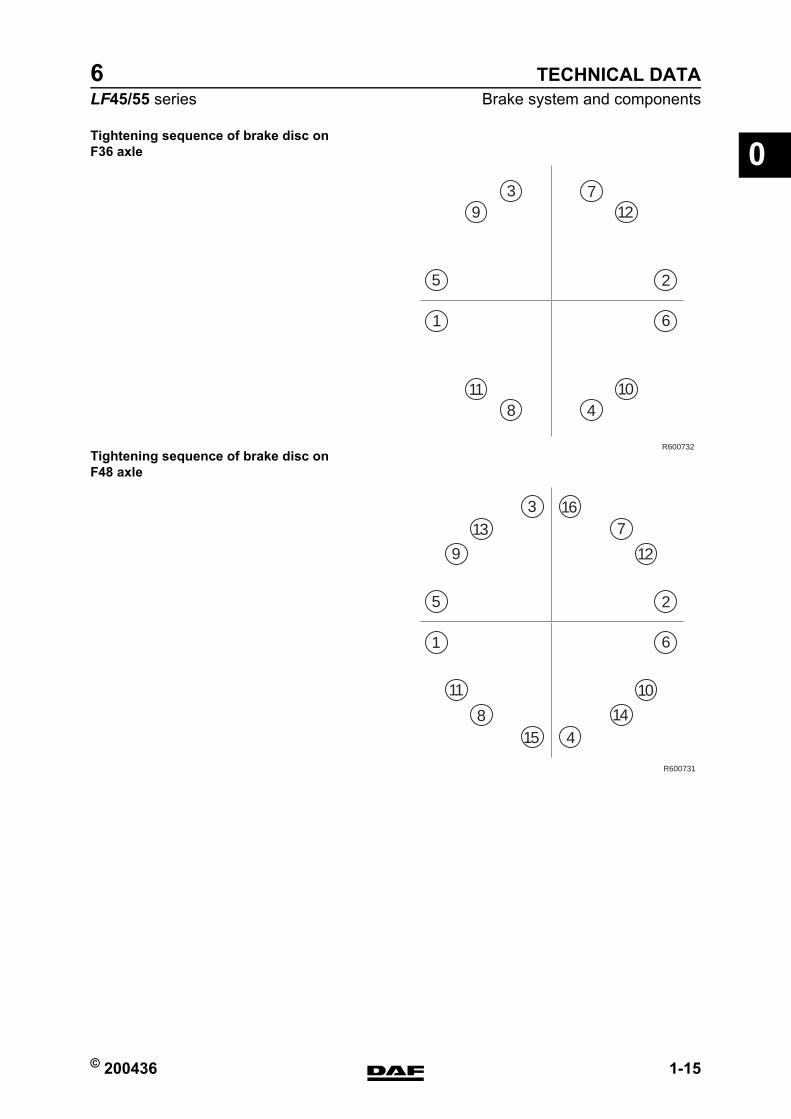
0Tightening sequence of brake disc on F36 axle
Tightening sequence of brake disc on F48 axle
1011
12
1
5 2
6
3 7
8
9
4
R600732
13
10
1415
11
16
12
1
5 2
6
37
8
9
4
R600731
https://www.truck-manuals.net/
TECHNICAL DATA
1-16 © 200436
Brake system and components
0
ΛΦ45/55 series6
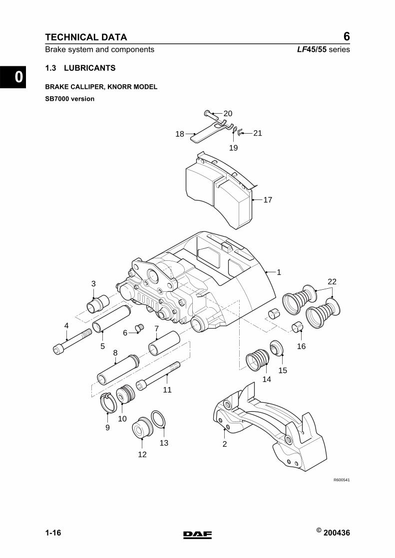
1.3 LUBRICANTS
BRAKE CALLIPER, KNORR MODEL
SB7000 version
R600541
18
122
7
19
1114
15
16
109
12
13 2
17
20
21
85
4
3
6
https://www.truck-manuals.net/
© 200436 1-17
Brake system and componentsTECHNICAL DATA
ΛΦ45/55 series6
0Renolit HLT2 (white) for parts 6, 7, 8, the adjusters (not shown), the brake cylinder lever and the flange surface for attachment of the brake cylinder 1448907Syntheso GL EP1 (green), for parts 3, 5 1448908
https://www.truck-manuals.net/
TECHNICAL DATA
1-18 © 200436
Brake system and components
0
ΛΦ45/55 series6
BRAKE CALLIPER, WABCO MODEL
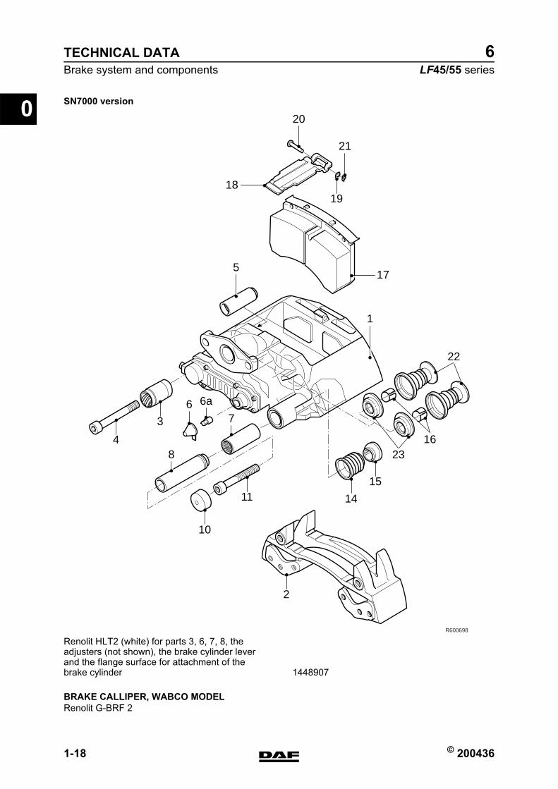
SN7000 version
R600698
17
22
2316
18
20
21
5
1
6 6a
7
8
19
15
14
2
11
10
4
3
Renolit HLT2 (white) for parts 3, 6, 7, 8, the adjusters (not shown), the brake cylinder lever and the flange surface for attachment of the brake cylinder 1448907
Renolit G-BRF 2
https://www.truck-manuals.net/
© 200436 1
ContentsDIAGNOSTICS
ΛΦ45/55 series6
1
1 DiagnosticsCONTENTSPage Date
1. DISC BRAKE CONSTRUCTION. . . . . . . . . . . . . . . . . . . . . . . . . . . . . . . . . . . . . 1-1 . . . . . 2004361.1 Fault-finding table . . . . . . . . . . . . . . . . . . . . . . . . . . . . . . . . . . . . . . . . . . . 1-1 . . . . . 200436
https://www.truck-manuals.net/

DIAGNOSTICS
2 © 200436
Contents
1
ΛΦ45/55 series6
https://www.truck-manuals.net/
© 200436 1-1
Disc brake constructionDIAGNOSTICS
ΛΦ45/55 series6
1
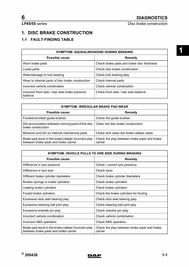
1. DISC BRAKE CONSTRUCTION1.1 FAULT-FINDING TABLE
SYMPTOM: SQUEALING/NOISE DURING BRAKING
Possible cause Remedy
Worn brake pads Check brake pads and brake disc thickness
Loose parts Check disc brake construction
Wear/damage to hub bearing Check hub bearing play
Wear to internal parts of disc brake construction Check internal parts
Incorrect vehicle combination Check vehicle combination
Incorrect front axle / rear axle brake pressure balance
Check front axle / rear axle balance
SYMPTOM: IRREGULAR BRAKE PAD WEAR
Possible cause Remedy
Fouled/corroded guide bushes Check the guide bushes
Dirt accumulation between moving parts of the disc brake construction
Clean the disc brake construction
Moisture and dirt on internal mechanical parts Check and clean the brake calliper seals
Brake pad stuck in the brake calliper Incorrect play between brake pads and brake carrier
Check the play between brake pads and brake carrier
SYMPTOM: VEHICLE PULLS TO ONE SIDE DURING BRAKING
Possible cause Remedy
Difference in tyre pressure Check / correct tyre pressure
Difference in tyre size Check tyres
Different brake cylinder diameters Check brake cylinder diameters
Broken springs in brake cylinders Check brake cylinders
Leaking brake cylinders Check brake cylinders
Fouled brake cylinders Check the brake cylinders for fouling
Excessive stub axle bearing play Check stub axle bearing play
Excessive steering ball joint play Check steering ball joint play
Excessive shackle pin play Check shackle pin play
Incorrect vehicle combination Check vehicle combination
Incorrect ABS operation Check ABS operation
Brake pad stuck in the brake calliper Incorrect play between brake pads and brake carrier
Check the play between brake pads and brake carrier
https://www.truck-manuals.net/
DIAGNOSTICS
1-2 © 200436
Disc brake construction
1
ΛΦ45/55 series6
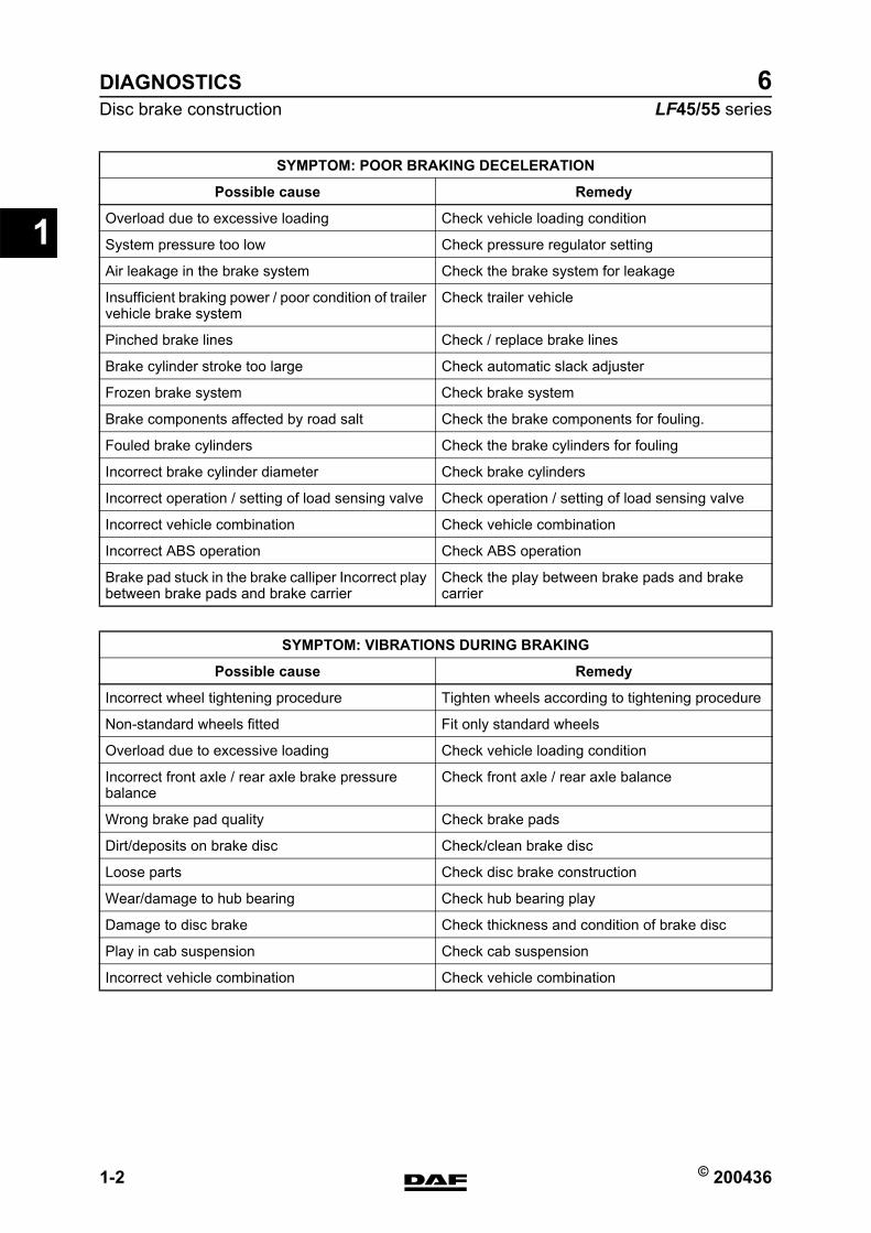
SYMPTOM: POOR BRAKING DECELERATION
Possible cause Remedy
Overload due to excessive loading Check vehicle loading condition
System pressure too low Check pressure regulator setting
Air leakage in the brake system Check the brake system for leakage
Insufficient braking power / poor condition of trailer vehicle brake system
Check trailer vehicle
Pinched brake lines Check / replace brake lines
Brake cylinder stroke too large Check automatic slack adjuster
Frozen brake system Check brake system
Brake components affected by road salt Check the brake components for fouling.
Fouled brake cylinders Check the brake cylinders for fouling
Incorrect brake cylinder diameter Check brake cylinders
Incorrect operation / setting of load sensing valve Check operation / setting of load sensing valve
Incorrect vehicle combination Check vehicle combination
Incorrect ABS operation Check ABS operation
Brake pad stuck in the brake calliper Incorrect play between brake pads and brake carrier
Check the play between brake pads and brake carrier
SYMPTOM: VIBRATIONS DURING BRAKING
Possible cause Remedy
Incorrect wheel tightening procedure Tighten wheels according to tightening procedure
Non-standard wheels fitted Fit only standard wheels
Overload due to excessive loading Check vehicle loading condition
Incorrect front axle / rear axle brake pressure balance
Check front axle / rear axle balance
Wrong brake pad quality Check brake pads
Dirt/deposits on brake disc Check/clean brake disc
Loose parts Check disc brake construction
Wear/damage to hub bearing Check hub bearing play
Damage to disc brake Check thickness and condition of brake disc
Play in cab suspension Check cab suspension
Incorrect vehicle combination Check vehicle combination
https://www.truck-manuals.net/
© 200436 1-3
Disc brake constructionDIAGNOSTICS
ΛΦ45/55 series6
1
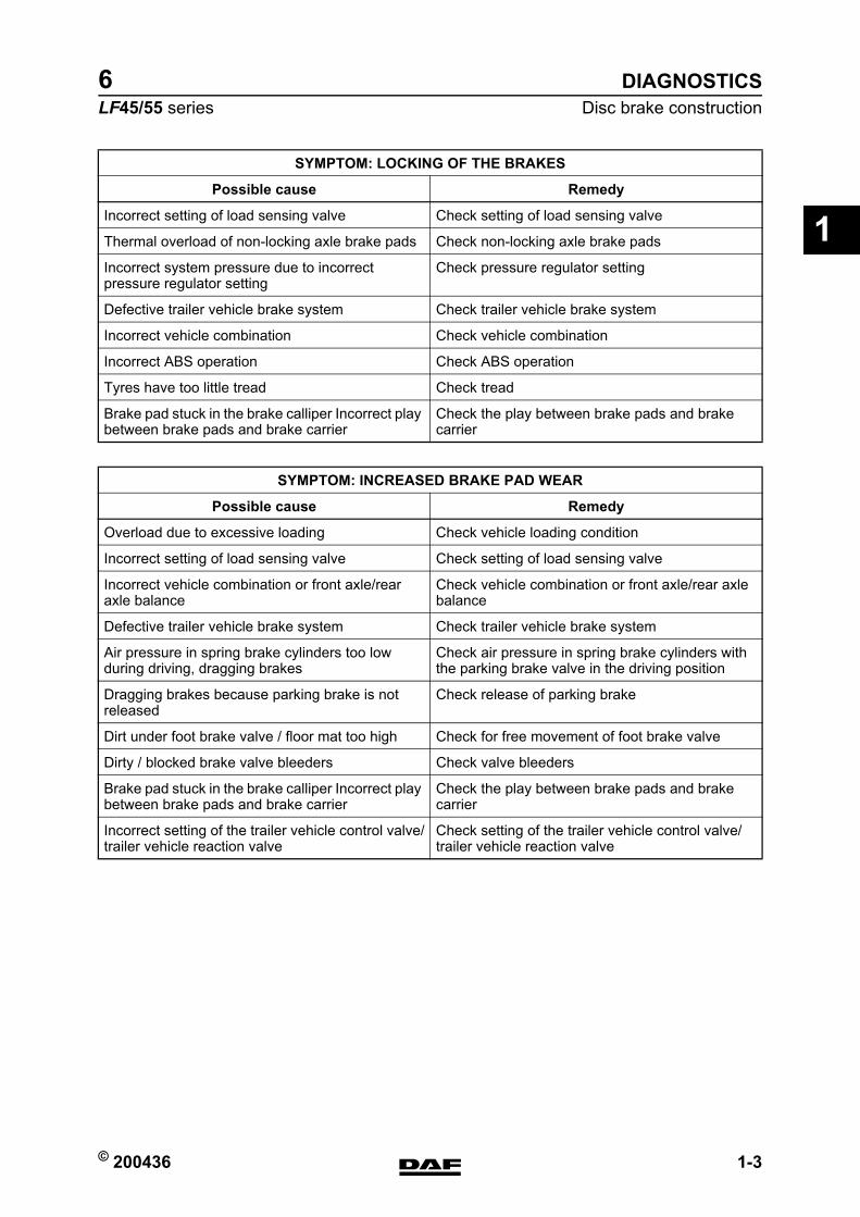
SYMPTOM: LOCKING OF THE BRAKES
Possible cause Remedy
Incorrect setting of load sensing valve Check setting of load sensing valve
Thermal overload of non-locking axle brake pads Check non-locking axle brake pads
Incorrect system pressure due to incorrect pressure regulator setting
Check pressure regulator setting
Defective trailer vehicle brake system Check trailer vehicle brake system
Incorrect vehicle combination Check vehicle combination
Incorrect ABS operation Check ABS operation
Tyres have too little tread Check tread
Brake pad stuck in the brake calliper Incorrect play between brake pads and brake carrier
Check the play between brake pads and brake carrier
SYMPTOM: INCREASED BRAKE PAD WEAR
Possible cause Remedy
Overload due to excessive loading Check vehicle loading condition
Incorrect setting of load sensing valve Check setting of load sensing valve
Incorrect vehicle combination or front axle/rear axle balance
Check vehicle combination or front axle/rear axle balance
Defective trailer vehicle brake system Check trailer vehicle brake system
Air pressure in spring brake cylinders too low during driving, dragging brakes
Check air pressure in spring brake cylinders with the parking brake valve in the driving position
Dragging brakes because parking brake is not released
Check release of parking brake
Dirt under foot brake valve / floor mat too high Check for free movement of foot brake valve
Dirty / blocked brake valve bleeders Check valve bleeders
Brake pad stuck in the brake calliper Incorrect play between brake pads and brake carrier
Check the play between brake pads and brake carrier
Incorrect setting of the trailer vehicle control valve/trailer vehicle reaction valve
Check setting of the trailer vehicle control valve/trailer vehicle reaction valve
https://www.truck-manuals.net/
DIAGNOSTICS
1-4 © 200436
Disc brake construction
1
ΛΦ45/55 series6
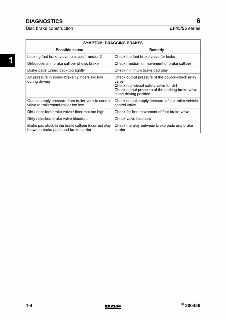
SYMPTOM: DRAGGING BRAKES
Possible cause Remedy
Leaking foot brake valve to circuit 1 and/or 2 Check the foot brake valve for leaks
Dirt/deposits in brake calliper of disc brake Check freedom of movement of brake calliper
Brake pads turned back too tightly Check minimum brake pad play
Air pressure in spring brake cylinders too low during driving
Check output pressure of the double-check relay valveCheck four-circuit safety valve for dirtCheck output pressure of the parking brake valve in the driving position
Output supply pressure from trailer vehicle control valve to trailer/semi-trailer too low
Check output supply pressure of the trailer vehicle control valve
Dirt under foot brake valve / floor mat too high Check for free movement of foot brake valve
Dirty / blocked brake valve bleeders Check valve bleeders
Brake pad stuck in the brake calliper Incorrect play between brake pads and brake carrier
Check the play between brake pads and brake carrier
https://www.truck-manuals.net/
© 200436 1
ContentsBRAKE DIAGRAMS FOR THE FULLY PNEUMATIC BRAKE SYSTEM
ΛΦ45/55 series6
2
2 Brake diagrams for the fully pneumatic brake systemCONTENTSPage Date
1. GENERAL . . . . . . . . . . . . . . . . . . . . . . . . . . . . . . . . . . . . . . . . . . . . . . . . . . . . . . 1-1 . . . . . 2004361.1 Brake diagrams . . . . . . . . . . . . . . . . . . . . . . . . . . . . . . . . . . . . . . . . . . . . . 1-1 . . . . . 200436
2. BRAKE DIAGRAMS FOR THE FULLY PNEUMATIC BRAKE SYSTEM . . . . . 2-1 . . . . . 2004362.1 Legend, brake diagrams for the fully pneumatic brake system . . . . . . . . . 2-1 . . . . . 2004362.2 Brake diagrams for the fully pneumatic brake system. . . . . . . . . . . . . . . . 2-2 . . . . . 200436
https://www.truck-manuals.net/
BRAKE DIAGRAMS FOR THE FULLY PNEUMATIC BRAKE SYSTEM
2 © 200436
Contents
2
ΛΦ45/55 series6
https://www.truck-manuals.net/
© 200436 1-1
GeneralBRAKE DIAGRAMS FOR THE FULLY PNEUMATIC BRAKE SYSTEM
ΛΦ45/55 series6
2
1. GENERAL1.1 BRAKE DIAGRAMS
Due to the large number of variants for each vehicle type and for each country, it is impractical to list all these variants.
Thus a selection has been shown which can form the basis for other variants.
https://www.truck-manuals.net/
BRAKE DIAGRAMS FOR THE FULLY PNEUMATIC BRAKE SYSTEM
1-2 © 200436
General
2
ΛΦ45/55 series6
https://www.truck-manuals.net/
© 200436 2-1
Brake diagrams for the fully pneumatic brake systemBRAKE DIAGRAMS FOR THE FULLY PNEUMATIC BRAKE SYSTEM
ΛΦ45/55 series6
2
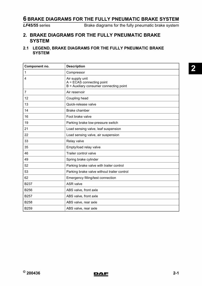
2. BRAKE DIAGRAMS FOR THE FULLY PNEUMATIC BRAKE SYSTEM
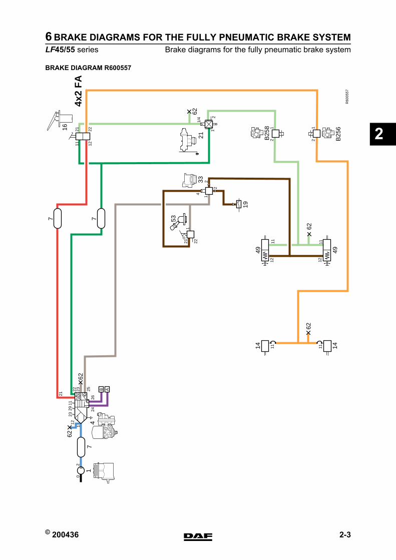
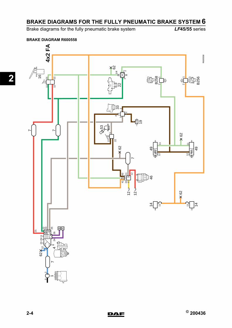
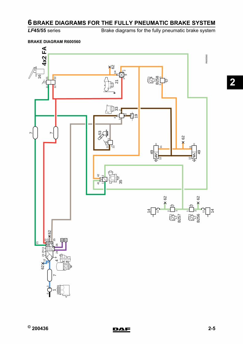
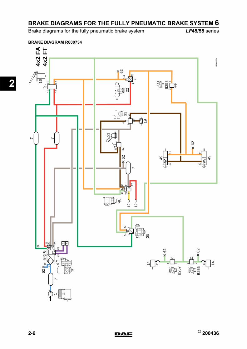
2.1 LEGEND, BRAKE DIAGRAMS FOR THE FULLY PNEUMATIC BRAKE SYSTEM
Component no. Description
1 Compressor
4 Air supply unitA = ECAS connecting pointB = Auxiliary consumer connecting point
7 Air reservoir
12 Coupling head
13 Quick-release valve
14 Brake chamber
16 Foot brake valve
19 Parking brake low-pressure switch
21 Load sensing valve, leaf suspension
22 Load sensing valve, air suspension
33 Relay valve
35 Empty/load relay valve
46 Trailer control valve
49 Spring brake cylinder
52 Parking brake valve with trailer control
53 Parking brake valve without trailer control
62 Emergency filling/test connection
B237 ASR valve
B256 ABS valve, front axle
B257 ABS valve, front axle
B258 ABS valve, rear axle
B259 ABS valve, rear axle
https://www.truck-manuals.net/
BRAKE DIAGRAMS FOR THE FULLY PNEUMATIC BRAKE SYSTEM
2-2 © 200436
Brake diagrams for the fully pneumatic brake system
2
ΛΦ45/55 series6
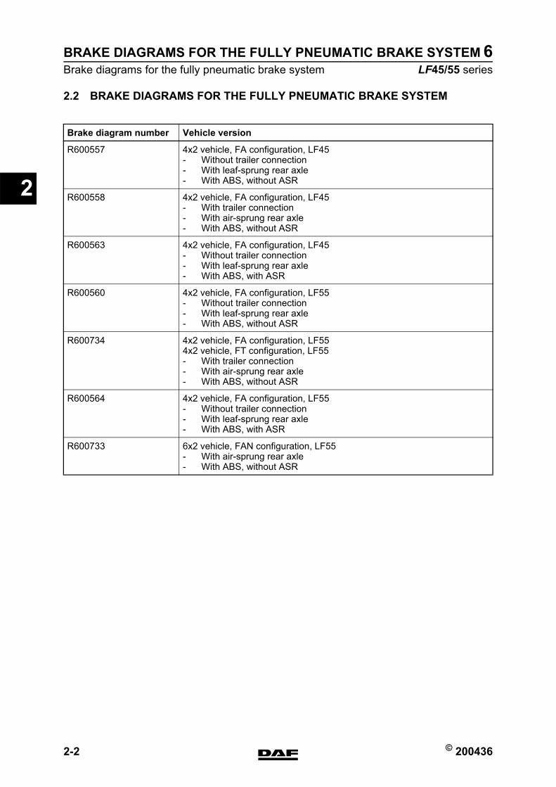
2.2 BRAKE DIAGRAMS FOR THE FULLY PNEUMATIC BRAKE SYSTEM
Brake diagram number Vehicle version
R600557 4x2 vehicle, FA configuration, LF45- Without trailer connection- With leaf-sprung rear axle- With ABS, without ASR
R600558 4x2 vehicle, FA configuration, LF45- With trailer connection- With air-sprung rear axle- With ABS, without ASR
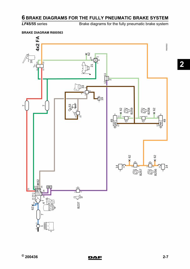
R600563 4x2 vehicle, FA configuration, LF45- Without trailer connection- With leaf-sprung rear axle- With ABS, with ASR
R600560 4x2 vehicle, FA configuration, LF55- Without trailer connection- With leaf-sprung rear axle- With ABS, without ASR
R600734 4x2 vehicle, FA configuration, LF554x2 vehicle, FT configuration, LF55- With trailer connection- With air-sprung rear axle- With ABS, without ASR
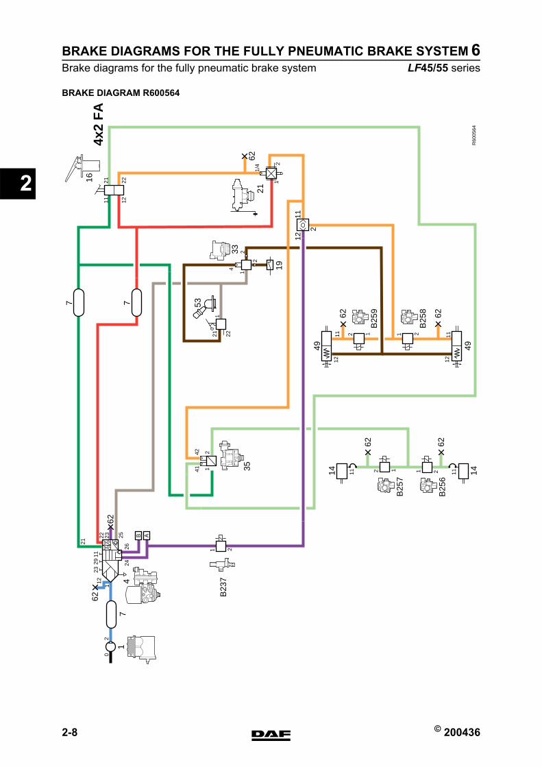
R600564 4x2 vehicle, FA configuration, LF55- Without trailer connection- With leaf-sprung rear axle- With ABS, with ASR
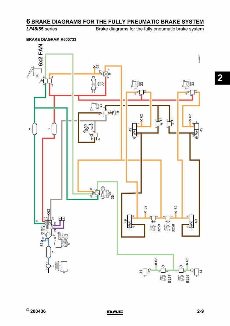
R600733 6x2 vehicle, FAN configuration, LF55- With air-sprung rear axle- With ABS, without ASR
https://www.truck-manuals.net/
© 200436 2-3
Brake diagrams for the fully pneumatic brake systemBRAKE DIAGRAMS FOR THE FULLY PNEUMATIC BRAKE SYSTEM
ΛΦ45/55 series6
2
BRAKE DIAGRAM R600557
R60
0557
4x2
FA
19
62
62
14 14
2
1112
11
4
2
2
1
1112
11
112
11 12
21 2224
26
B
0u
up
p22 23 25 A
7 7
62
62
49 49
16
21 22
1
12
12
4
B25
8
B25
6
1
53
33
2911
7
62
21
23
21
12
1/4
https://www.truck-manuals.net/
BRAKE DIAGRAMS FOR THE FULLY PNEUMATIC BRAKE SYSTEM
2-4 © 200436
Brake diagrams for the fully pneumatic brake system
2
ΛΦ45/55 series6
BRAKE DIAGRAM R600558
R60
0558
4x2
FA
19
12 B
256
62
14 14
2
1112
11
4
2
2
1
1112
11
112
23
11 12
21 2224
26
B
0u
up
p21
22 23 25 A
7 7
712
46
12
62
62
49 49
16
21
4341
42
22
1
12
4
B25
8
1
53
33
121122
2911
7
62
6222
12
1/4
https://www.truck-manuals.net/
© 200436 2-5
Brake diagrams for the fully pneumatic brake systemBRAKE DIAGRAMS FOR THE FULLY PNEUMATIC BRAKE SYSTEM
ΛΦ45/55 series6
2
BRAKE DIAGRAM R600560
R60
0560
4x2
FA
19
35
2141
42
62
62
14 14
2
1112
11
4
2
2
1
1112
11
112
11 12
21 2224
26
B
0u
up
p22 23 25 A
7 7
62
62
49 49
16
21 22
1
12
12
4
B25
8
B25
7
21
B25
6
1
53
33
2911
7
62 62
21
23
21
12
1/4
https://www.truck-manuals.net/
BRAKE DIAGRAMS FOR THE FULLY PNEUMATIC BRAKE SYSTEM
2-6 © 200436
Brake diagrams for the fully pneumatic brake system
2
ΛΦ45/55 series6
BRAKE DIAGRAM R600734
R60
0734
4x2
FA
4x2
FT
1935
2141
42
62
14 14
2
11
1211
4
2
2
1
1112
11
112
23
11 12
21 2224
26
B
0u
up
p21
22 23 25 A
7 7
712
46
12
62
62
49 49
16
21
4341
4222
1
12
4
B25
8
1
53
33
121122
2911
7
62 62
62
12
B25
7
21
B25
6
221
2
1/4
https://www.truck-manuals.net/
© 200436 2-7
Brake diagrams for the fully pneumatic brake systemBRAKE DIAGRAMS FOR THE FULLY PNEUMATIC BRAKE SYSTEM
ΛΦ45/55 series6
2
BRAKE DIAGRAM R600563
R60
0563
4x2
FA
19
2
1211
62
62
14 14
2
11
1211
4
2
2
1
1112
11
112
11 12
21 2224
26
B
0u
up
p22 23 25 A
7 7
62
62
49 49
16
21 22
1
21
4
B25
8
12
B25
9
21
B25
6
1
53
33
2911
7
62
62 62
21
23
21
12
B25
7
21
B23
7
12
1/4
https://www.truck-manuals.net/
BRAKE DIAGRAMS FOR THE FULLY PNEUMATIC BRAKE SYSTEM
2-8 © 200436
Brake diagrams for the fully pneumatic brake system
2
ΛΦ45/55 series6
BRAKE DIAGRAM R600564
R60
0564
4x2
FA
19
2
1211
62
62
14 14
2
11
1211
4
2
2
1
1112
11
112
11 12
21 2224
26
B
0u
up
p22 23 25 A
7 7
62
62
49 49
16
21 22
1
21
4
B25
8
12
B25
9
21
B25
6
1
53
33
2911
7
62
62 62
21
23
21
12
B25
7
B23
721
12
1/4
35
2141
42
https://www.truck-manuals.net/
© 200436 2-9
Brake diagrams for the fully pneumatic brake systemBRAKE DIAGRAMS FOR THE FULLY PNEUMATIC BRAKE SYSTEM
ΛΦ45/55 series6
2
BRAKE DIAGRAM R600733
R60
0733
6x2
FA
N62
14 14
2
11
1211
4
2
2
1
1112
11
112
2311 12
21 2224
26
B
0u
up
p21
22 23 25 A
7 7
62
62
62
49 49
16
21 22
1
4
11 22
B25
9
B25
8
1
53
33
4
2
1
4
2
1
33 33
2911
7
62
62 62
12
B25
7
21
B25
6
1211 11
1262
49 49
62
19
35
131
2 131
2
2141
42
221
2
1/4
https://www.truck-manuals.net/
BRAKE DIAGRAMS FOR THE FULLY PNEUMATIC BRAKE SYSTEM
2-10 © 200436
Brake diagrams for the fully pneumatic brake system
2
ΛΦ45/55 series6
https://www.truck-manuals.net/
© 200436 1
ContentsOPERATION OF BRAKE COMPONENTS
ΛΦ45/55 series6
3
3 Operation of brake componentsCONTENTSPage Date
1. GENERAL . . . . . . . . . . . . . . . . . . . . . . . . . . . . . . . . . . . . . . . . . . . . . . . . . . . . . . 1-1 . . . . . 2004361.1 Overview drawing, Wabco PAN 17 and PAN 19-1+ disc brake
construction . . . . . . . . . . . . . . . . . . . . . . . . . . . . . . . . . . . . . . . . . . . . . . . . 1-1 . . . . . 2004361.2 Overview drawing, Wabco PAN 19-2 disc brake construction. . . . . . . . . . 1-2 . . . . . 2004361.3 Overview drawing, Knorr SB700 disc brake construction . . . . . . . . . . . . . 1-3 . . . . . 2004361.4 Overview drawing, Knorr SN700 disc brake construction . . . . . . . . . . . . . 1-4 . . . . . 200436
2. DESCRIPTION OF COMPONENTS . . . . . . . . . . . . . . . . . . . . . . . . . . . . . . . . . . 2-1 . . . . . 2004362.1 Compressor . . . . . . . . . . . . . . . . . . . . . . . . . . . . . . . . . . . . . . . . . . . . . . . . 2-1 . . . . . 2004362.2 Air supply unit . . . . . . . . . . . . . . . . . . . . . . . . . . . . . . . . . . . . . . . . . . . . . . 2-2 . . . . . 2004362.3 Water blow-off valve . . . . . . . . . . . . . . . . . . . . . . . . . . . . . . . . . . . . . . . . . 2-5 . . . . . 2004362.4 Foot brake valve . . . . . . . . . . . . . . . . . . . . . . . . . . . . . . . . . . . . . . . . . . . . 2-6 . . . . . 2004362.5 Relay valve . . . . . . . . . . . . . . . . . . . . . . . . . . . . . . . . . . . . . . . . . . . . . . . . 2-7 . . . . . 2004362.6 Empty/load relay valve . . . . . . . . . . . . . . . . . . . . . . . . . . . . . . . . . . . . . . . 2-8 . . . . . 2004362.7 Load sensing valve, air suspension. . . . . . . . . . . . . . . . . . . . . . . . . . . . . . 2-10 . . . . 2004362.8 Load sensing valve, leaf suspension. . . . . . . . . . . . . . . . . . . . . . . . . . . . . 2-13 . . . . 2004362.9 ABS valve . . . . . . . . . . . . . . . . . . . . . . . . . . . . . . . . . . . . . . . . . . . . . . . . 2-16 . . . . 2004362.10 Two-way valve. . . . . . . . . . . . . . . . . . . . . . . . . . . . . . . . . . . . . . . . . . . . . . 2-19 . . . . 2004362.11 ASR solenoid valve . . . . . . . . . . . . . . . . . . . . . . . . . . . . . . . . . . . . . . . . . . 2-20 . . . . 2004362.12 Emergency filling/test connection . . . . . . . . . . . . . . . . . . . . . . . . . . . . . . . 2-21 . . . . 2004362.13 Brake cylinder . . . . . . . . . . . . . . . . . . . . . . . . . . . . . . . . . . . . . . . . . . . . . . 2-22 . . . . 2004362.14 Parking brake valve . . . . . . . . . . . . . . . . . . . . . . . . . . . . . . . . . . . . . . . . . . 2-23 . . . . 2004362.15 Spring brake cylinder . . . . . . . . . . . . . . . . . . . . . . . . . . . . . . . . . . . . . . . . . 2-27 . . . . 2004362.16 Trailer control valve . . . . . . . . . . . . . . . . . . . . . . . . . . . . . . . . . . . . . . . . . . 2-29 . . . . 2004362.17 Coupling head . . . . . . . . . . . . . . . . . . . . . . . . . . . . . . . . . . . . . . . . . . . . . . 2-32 . . . . 2004362.18 Disc brake construction, Wabco model . . . . . . . . . . . . . . . . . . . . . . . . . . . 2-33 . . . . 2004362.19 Disc brake construction, Knorr model . . . . . . . . . . . . . . . . . . . . . . . . . . . . 2-35 . . . . 200436
https://www.truck-manuals.net/
OPERATION OF BRAKE COMPONENTS
2 © 200436
Contents
3
ΛΦ45/55 series6
https://www.truck-manuals.net/
© 200436 1-1
GeneralOPERATION OF BRAKE COMPONENTS
ΛΦ45/55 series6
3
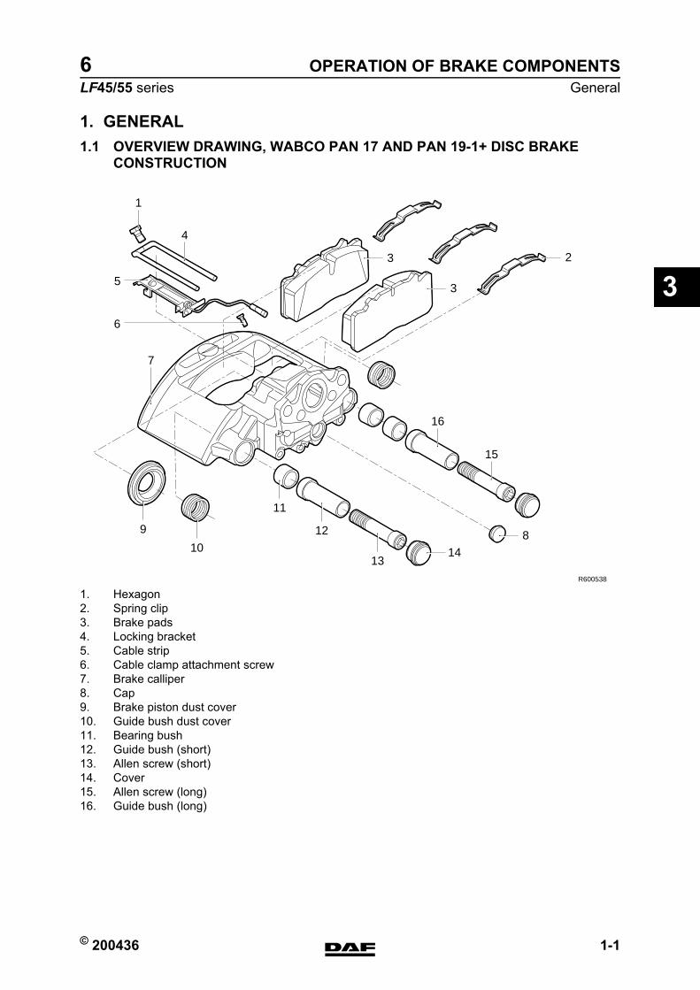
1. GENERAL1.1 OVERVIEW DRAWING, WABCO PAN 17 AND PAN 19-1+ DISC BRAKE
CONSTRUCTION
R600538
4
7
15
16
1
11
12
13
9
6
10
3
3
2
14
8
5
1. Hexagon2. Spring clip3. Brake pads4. Locking bracket5. Cable strip6. Cable clamp attachment screw7. Brake calliper8. Cap9. Brake piston dust cover10. Guide bush dust cover11. Bearing bush12. Guide bush (short)13. Allen screw (short)14. Cover15. Allen screw (long)16. Guide bush (long)
https://www.truck-manuals.net/

OPERATION OF BRAKE COMPONENTS
1-2 © 200436
General
3
ΛΦ45/55 series6
1.2 OVERVIEW DRAWING, WABCO PAN 19-2 DISC BRAKE CONSTRUCTION
R600539
7
14
16
13
6
17
15
18
9
12
3
4
11
1910
8
1 2
5
1. Brake calliper2. Brake calliper carrier3. Wheel-side brake pad4. Drive-side brake pad5. Spring clip6. Hexagon7. Locking bracket8. Cable strip9. Cable clamp attachment screw10. Cap11. Brake piston dust cover12. Guide bush dust cover13. Bearing bush14. Allen screw (long)15. Allen screw (short)16. Guide bush (long)17. Guide bush (short)18. Cover19. Cover
https://www.truck-manuals.net/
© 200436 1-3
GeneralOPERATION OF BRAKE COMPONENTS
ΛΦ45/55 series6
3
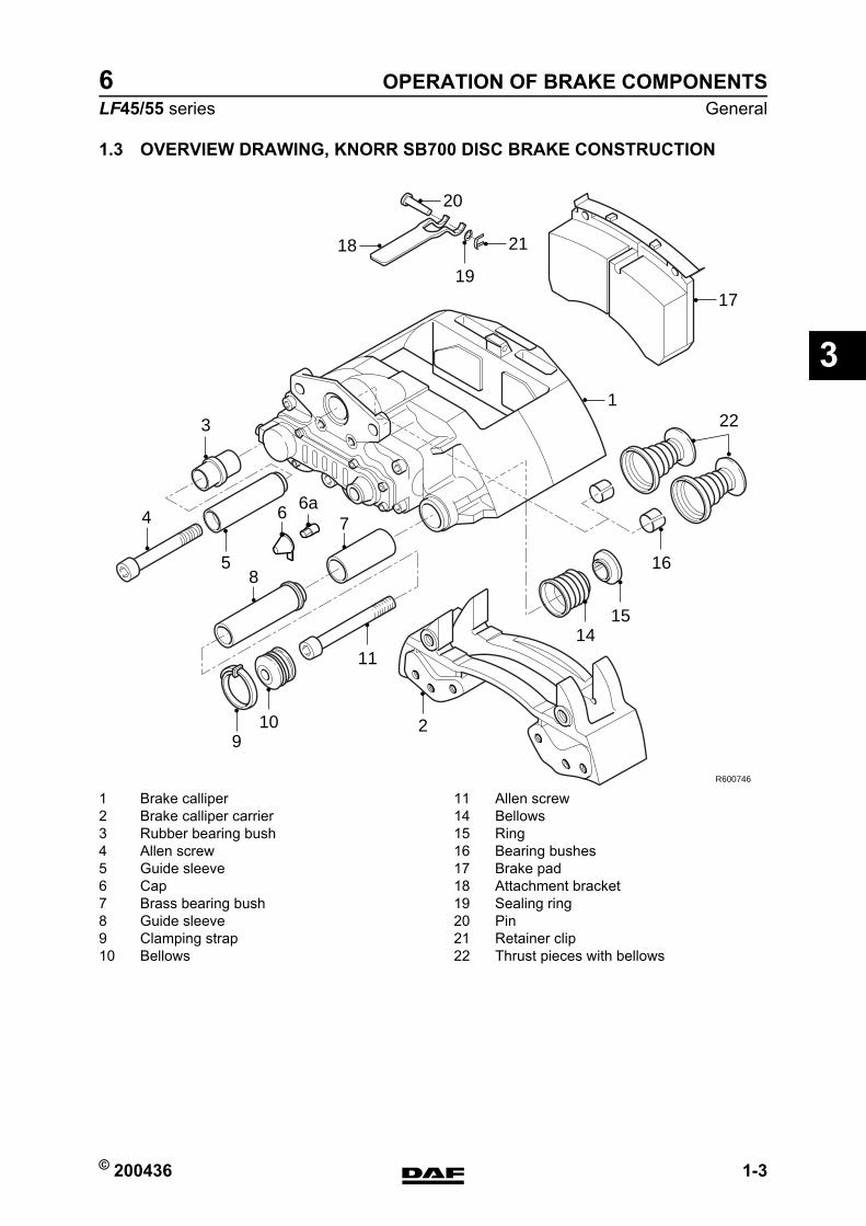
1.3 OVERVIEW DRAWING, KNORR SB700 DISC BRAKE CONSTRUCTION
1 Brake calliper 11 Allen screw2 Brake calliper carrier 14 Bellows3 Rubber bearing bush 15 Ring4 Allen screw 16 Bearing bushes5 Guide sleeve 17 Brake pad6 Cap 18 Attachment bracket7 Brass bearing bush 19 Sealing ring8 Guide sleeve 20 Pin9 Clamping strap 21 Retainer clip10 Bellows 22 Thrust pieces with bellows
R600746
18
122
7
19
1114
15
16
109
2
17
20
21
85
4
3
6 6a
https://www.truck-manuals.net/
OPERATION OF BRAKE COMPONENTS
1-4 © 200436
General
3
ΛΦ45/55 series6
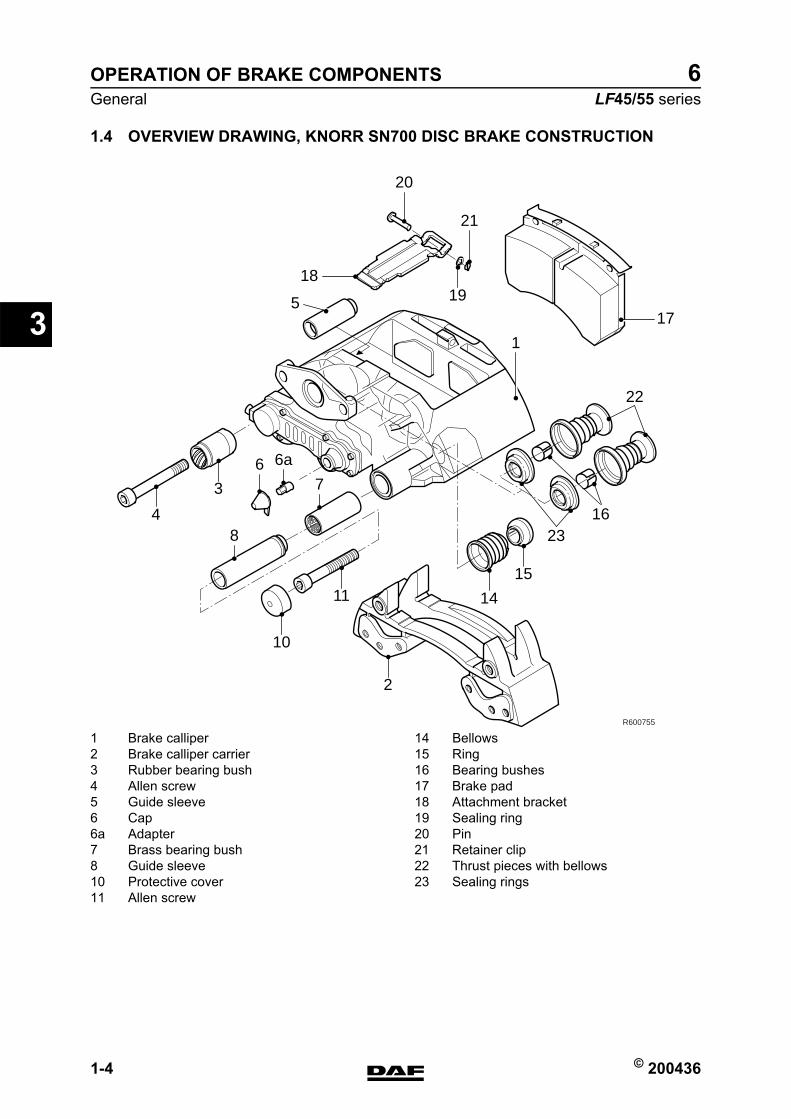
1.4 OVERVIEW DRAWING, KNORR SN700 DISC BRAKE CONSTRUCTION
1 Brake calliper 14 Bellows2 Brake calliper carrier 15 Ring3 Rubber bearing bush 16 Bearing bushes4 Allen screw 17 Brake pad5 Guide sleeve 18 Attachment bracket6 Cap 19 Sealing ring6a Adapter 20 Pin7 Brass bearing bush 21 Retainer clip8 Guide sleeve 22 Thrust pieces with bellows10 Protective cover 23 Sealing rings11 Allen screw
R600755
17
22
2316
18
20
21
5
1
6 6a
7
8
19
15
14
2
11
10
4
3
https://www.truck-manuals.net/
© 200436 2-1
Description of componentsOPERATION OF BRAKE COMPONENTS
ΛΦ45/55 series6
3
2. DESCRIPTION OF COMPONENTS2.1 COMPRESSOR
The compressor is a 225-cm3 one-cylinder design with a water-cooled cylinder head. The compressor is mounted on the left side of the engine against the flywheel housing.The compressor is driven by the camshaft gear via a gear wheel.
https://www.truck-manuals.net/
OPERATION OF BRAKE COMPONENTS
2-2 © 200436
Description of components
3
ΛΦ45/55 series6
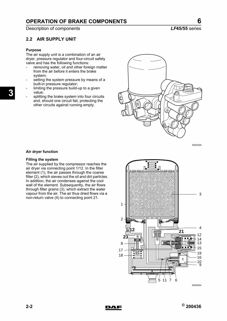
2.2 AIR SUPPLY UNIT
PurposeThe air supply unit is a combination of an air dryer, pressure regulator and four-circuit safety valve and has the following functions:- removing water, oil and other foreign matter
from the air before it enters the brake system;
- setting the system pressure by means of a built-in pressure regulator;
- limiting the pressure build-up to a given value;
- splitting the brake system into four circuits and, should one circuit fail, protecting the other circuits against running empty.
Air dryer function
Filling the systemThe air supplied by the compressor reaches the air dryer via connecting point 1/12. In the filter element (1), the air passes through the coarse filter (2), which sieves out the oil and dirt particles.In addition, the air condenses against the cool wall of the element. Subsequently, the air flows through filter grains (3), which extract the water vapour from the air. The air thus dried flows via a non-return valve (4) to connecting point 21.
R600359
R600504
109
67115
8
bc
a
16
12211/12
23
3
4
2
1
1817
14131519
https://www.truck-manuals.net/
© 200436 2-3
Description of componentsOPERATION OF BRAKE COMPONENTS
ΛΦ45/55 series6
3
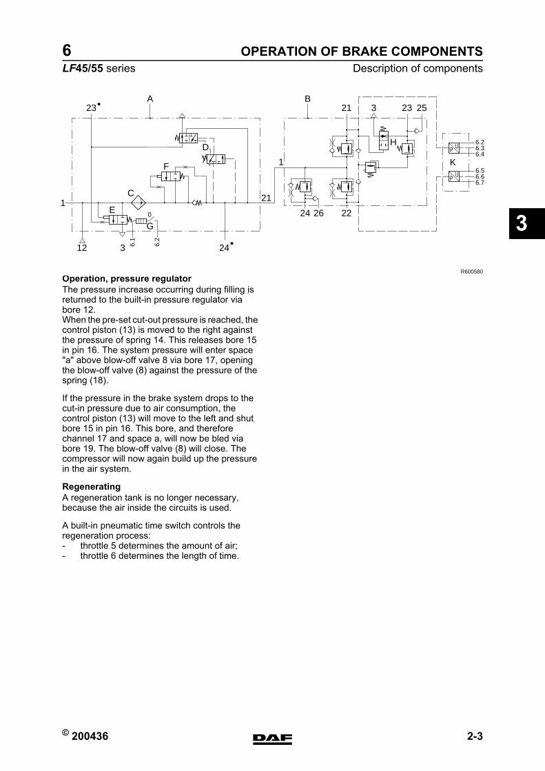
Operation, pressure regulatorThe pressure increase occurring during filling is returned to the built-in pressure regulator via bore 12.When the pre-set cut-out pressure is reached, the control piston (13) is moved to the right against the pressure of spring 14. This releases bore 15 in pin 16. The system pressure will enter space "a" above blow-off valve 8 via bore 17, opening the blow-off valve (8) against the pressure of the spring (18).
If the pressure in the brake system drops to the cut-in pressure due to air consumption, the control piston (13) will move to the left and shut bore 15 in pin 16. This bore, and therefore channel 17 and space a, will now be bled via bore 19. The blow-off valve (8) will close. The compressor will now again build up the pressure in the air system.
RegeneratingA regeneration tank is no longer necessary, because the air inside the circuits is used.
A built-in pneumatic time switch controls the regeneration process:- throttle 5 determines the amount of air;- throttle 6 determines the length of time.
24
21
1F
D H
K
3
A
E
C
G
1
12 24
26 22
2123 3 23 25
P U6.26.36.4
6.1
6.2
P U6.56.66.7
B
R600580
0
https://www.truck-manuals.net/
OPERATION OF BRAKE COMPONENTS
2-4 © 200436
Description of components
3
ΛΦ45/55 series6
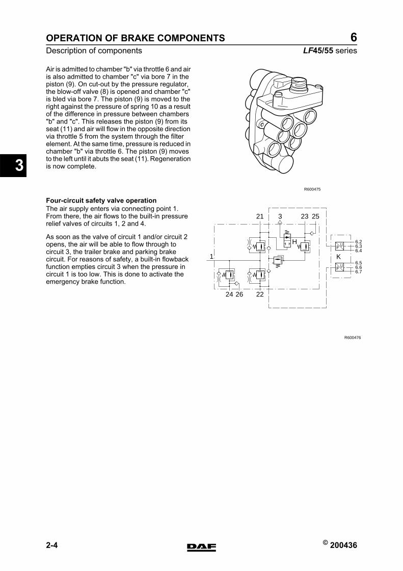
Air is admitted to chamber "b" via throttle 6 and air is also admitted to chamber "c" via bore 7 in the piston (9). On cut-out by the pressure regulator, the blow-off valve (8) is opened and chamber "c" is bled via bore 7. The piston (9) is moved to the right against the pressure of spring 10 as a result of the difference in pressure between chambers "b" and "c". This releases the piston (9) from its seat (11) and air will flow in the opposite direction via throttle 5 from the system through the filter element. At the same time, pressure is reduced in chamber "b" via throttle 6. The piston (9) moves to the left until it abuts the seat (11). Regeneration is now complete.
Four-circuit safety valve operationThe air supply enters via connecting point 1. From there, the air flows to the built-in pressure relief valves of circuits 1, 2 and 4.
As soon as the valve of circuit 1 and/or circuit 2 opens, the air will be able to flow through to circuit 3, the trailer brake and parking brake circuit. For reasons of safety, a built-in flowback function empties circuit 3 when the pressure in circuit 1 is too low. This is done to activate the emergency brake function.
R600475
24
1
H
K
26 22
21 3 23 25
P U6.26.36.4
P U6.56.66.7
R600476
https://www.truck-manuals.net/
© 200436 2-5
Description of componentsOPERATION OF BRAKE COMPONENTS
ΛΦ45/55 series6
3
2.3 WATER BLOW-OFF VALVE
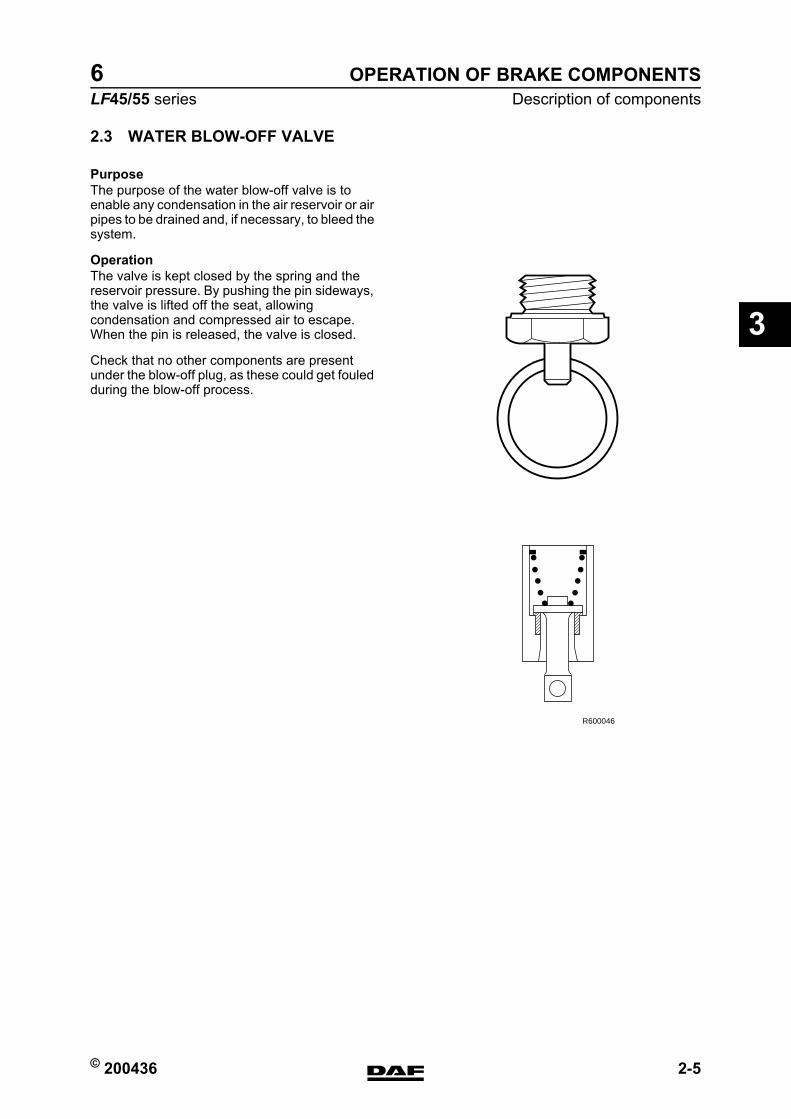
PurposeThe purpose of the water blow-off valve is to enable any condensation in the air reservoir or air pipes to be drained and, if necessary, to bleed the system.
OperationThe valve is kept closed by the spring and the reservoir pressure. By pushing the pin sideways, the valve is lifted off the seat, allowing condensation and compressed air to escape. When the pin is released, the valve is closed.
Check that no other components are present under the blow-off plug, as these could get fouled during the blow-off process.
R600046
https://www.truck-manuals.net/
OPERATION OF BRAKE COMPONENTS
2-6 © 200436
Description of components
3
ΛΦ45/55 series6
2.4 FOOT BRAKE VALVE
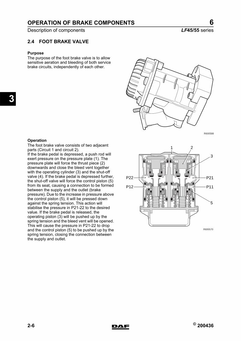
PurposeThe purpose of the foot brake valve is to allow sensitive aeration and bleeding of both service brake circuits, independently of each other.
OperationThe foot brake valve consists of two adjacent parts (Circuit 1 and circuit 2).If the brake pedal is depressed, a push rod will exert pressure on the pressure plate (1). The pressure plate will force the thrust piece (2) downwards and close the bleed vent together with the operating cylinder (3) and the shut-off valve (4). If the brake pedal is depressed further, the shut-off valve will force the control piston (5) from its seat, causing a connection to be formed between the supply and the outlet (brake pressure). Due to the increase in pressure above the control piston (5), it will be pressed down against the spring tension. This action will stabilise the pressure in P21-22 to the desired value. If the brake pedal is released, the operating piston (3) will be pushed up by the spring tension and the bleed vent will be opened. This will cause the pressure in P21-22 to drop and the control piston (5) to be pushed up by the spring tension, closing the connection between the supply and outlet.
R600588
R600570
P21P22
P11P12
2
3
5
1
https://www.truck-manuals.net/
© 200436 2-7
Description of componentsOPERATION OF BRAKE COMPONENTS
ΛΦ45/55 series6
3
2.5 RELAY VALVE
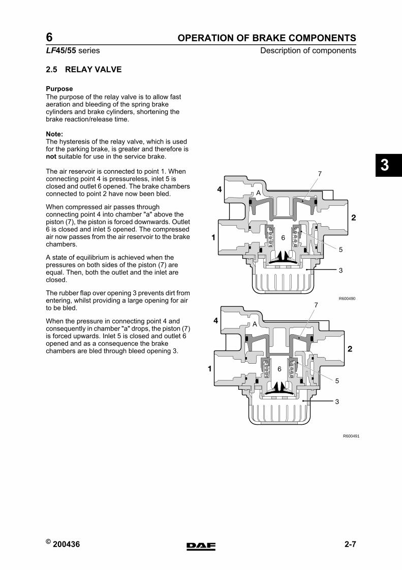
PurposeThe purpose of the relay valve is to allow fast aeration and bleeding of the spring brake cylinders and brake cylinders, shortening the brake reaction/release time.
Note:The hysteresis of the relay valve, which is used for the parking brake, is greater and therefore is not suitable for use in the service brake.
The air reservoir is connected to point 1. When connecting point 4 is pressureless, inlet 5 is closed and outlet 6 opened. The brake chambers connected to point 2 have now been bled.
When compressed air passes through connecting point 4 into chamber "a" above the piston (7), the piston is forced downwards. Outlet 6 is closed and inlet 5 opened. The compressed air now passes from the air reservoir to the brake chambers.
A state of equilibrium is achieved when the pressures on both sides of the piston (7) are equal. Then, both the outlet and the inlet are closed.
The rubber flap over opening 3 prevents dirt from entering, whilst providing a large opening for air to be bled.
When the pressure in connecting point 4 and consequently in chamber "a" drops, the piston (7) is forced upwards. Inlet 5 is closed and outlet 6 opened and as a consequence the brake chambers are bled through bleed opening 3.
R600490
2
1 6
4 A
5
3
7
R600491
2
1 6
4 A
5
3
7
https://www.truck-manuals.net/
OPERATION OF BRAKE COMPONENTS
2-8 © 200436
Description of components
3
ΛΦ45/55 series6
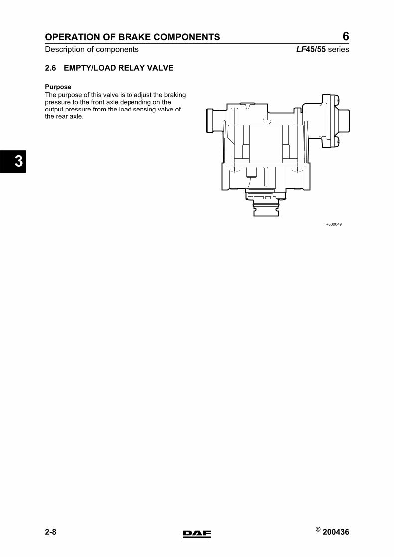
2.6 EMPTY/LOAD RELAY VALVE
PurposeThe purpose of this valve is to adjust the braking pressure to the front axle depending on the output pressure from the load sensing valve of the rear axle.
R600049
https://www.truck-manuals.net/

© 200436 2-9
Description of componentsOPERATION OF BRAKE COMPONENTS
ΛΦ45/55 series6
3
Empty/load relay valveIn rest position, relay piston 4 is in its upper position and connecting point 2 (brake cylinders on front axle) is bled via connecting point 3.
When the foot brake is applied, the relay piston is forced downwards via connecting point 41, thus opening valve 5. At connecting point 2 pressure is built up until a set value is reached. Relay piston 4 is then once again forced upwards until there is a state of equilibrium.Air has also entered simultaneously via connection point 42 (load sensing valve). This will force piston 6 to the left. Through a bore in piston 6 the pressure now also reaches the central surface of the relay piston (4). This pressure will depend on the loading of the rear axle. As a consequence, the output pressure of this valve is in part dependent on the braking pressure of the rear axle.The input pressure at connecting point 41 is also applied to the left-hand side of piston 6, via two openings. If no pressure enters via connecting point 42, due to a fault, piston 6 will be forced to the right. The pressure at connecting point 41 will now also reach the central surface of relay piston 4. In this situation, the valve simply operates as a relay valve, and will no longer reduce.
When the foot brake is released, the pressure at connecting points 41 and 42 will disappear. Relay piston 4 will be forced upwards by the pressure beneath it, thus opening the bleed system.
1 2
3
4241
R600493
4 6
5
1 2
3
4241
R600494
https://www.truck-manuals.net/
OPERATION OF BRAKE COMPONENTS
2-10 © 200436
Description of components
3
ΛΦ45/55 series6
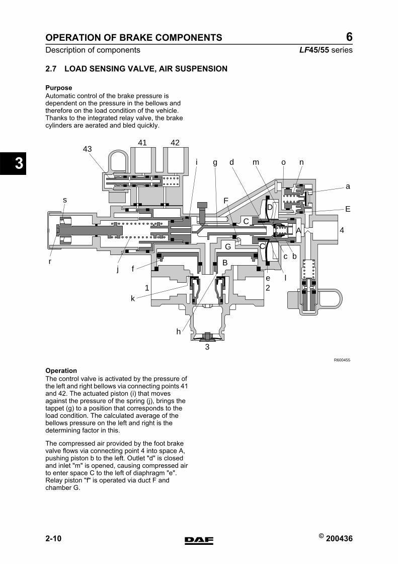
2.7 LOAD SENSING VALVE, AIR SUSPENSION
PurposeAutomatic control of the brake pressure is dependent on the pressure in the bellows and therefore on the load condition of the vehicle. Thanks to the integrated relay valve, the brake cylinders are aerated and bled quickly.
OperationThe control valve is activated by the pressure of the left and right bellows via connecting points 41 and 42. The actuated piston (i) that moves against the pressure of the spring (j), brings the tappet (g) to a position that corresponds to the load condition. The calculated average of the bellows pressure on the left and right is the determining factor in this.
The compressed air provided by the foot brake valve flows via connecting point 4 into space A, pushing piston b to the left. Outlet "d" is closed and inlet "m" is opened, causing compressed air to enter space C to the left of diaphragm "e". Relay piston "f" is operated via duct F and chamber G.
4341 42
3
21
4
E
C
C
FD
A
G
B
a
nomdgi
j fe l
k
h
c b
R600455
r
s
https://www.truck-manuals.net/
© 200436 2-11
Description of componentsOPERATION OF BRAKE COMPONENTS
ΛΦ45/55 series6
3
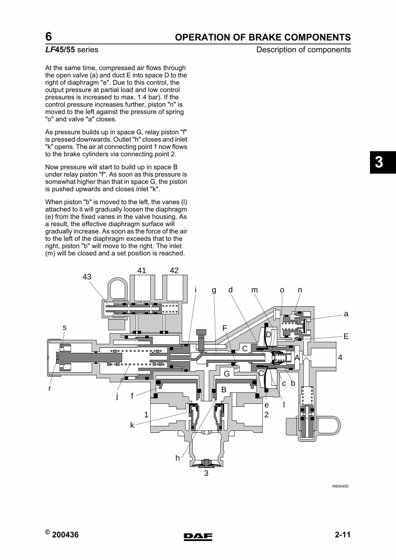
At the same time, compressed air flows through the open valve (a) and duct E into space D to the right of diaphragm "e". Due to this control, the output pressure at partial load and low control pressures is increased to max. 1.4 bar). If the control pressure increases further, piston "n" is moved to the left against the pressure of spring "o" and valve "a" closes.
As pressure builds up in space G, relay piston "f" is pressed downwards. Outlet "h" closes and inlet "k" opens. The air at connecting point 1 now flows to the brake cylinders via connecting point 2.
Now pressure will start to build up in space B under relay piston "f". As soon as this pressure is somewhat higher than that in space G, the piston is pushed upwards and closes inlet "k".
When piston "b" is moved to the left, the vanes (l) attached to it will gradually loosen the diaphragm (e) from the fixed vanes in the valve housing. As a result, the effective diaphragm surface will gradually increase. As soon as the force of the air to the left of the diaphragm exceeds that to the right, piston "b" will move to the right. The inlet (m) will be closed and a set position is reached.
4341 42
3
21
4
E
C
C
FD
A
G
B
a
nomdgi
j fe l
k
h
c b
R600455
r
s
https://www.truck-manuals.net/
OPERATION OF BRAKE COMPONENTS
2-12 © 200436
Description of components
3
ΛΦ45/55 series6
The position of tappet "g", which depends on the position of piston "i", is indicative of the effective diaphragm surface and therefore of the output brake pressure.The position of tappet "g" determines to what extent piston "b" must be moved with the vane disc (l) to allow the valve to build up pressure. Due to this movement, the effective surface of the diaphragm will alter.In full-load position, this surface and that of piston "b" are equally large. The control pressure at connecting point 4 is therefore let through (ratio 1:1) to spaces C and G. The output pressure at 2 will now be equal to the control pressure at connecting point 4.
If the pressure decreases at connecting point 4, piston "b" will be pushed to the right by the pressure in space C. Bleed vent "d" will open and the pressure in spaces C and G will fall. The relay piston will be pushed up due to the pressure still present in space B, causing bleed vent "h" to open. The pressure at connecting point 2 will now fall via bleed vent 3.
A stop bolt in front of tappet "g" ensures that this valve can always provide the minimum brake pressure if the bellows pressure delivered falls below the minimum effective pressure due to a fault. The factory setting of this bolt must not be changed.
The simulation connection (43) is for controlling the valve. By connecting an air hose to it, the bellows will be pneumatically closed, allowing the valve to be operated with a random test pressure.
https://www.truck-manuals.net/
© 200436 2-13
Description of componentsOPERATION OF BRAKE COMPONENTS
ΛΦ45/55 series6
3
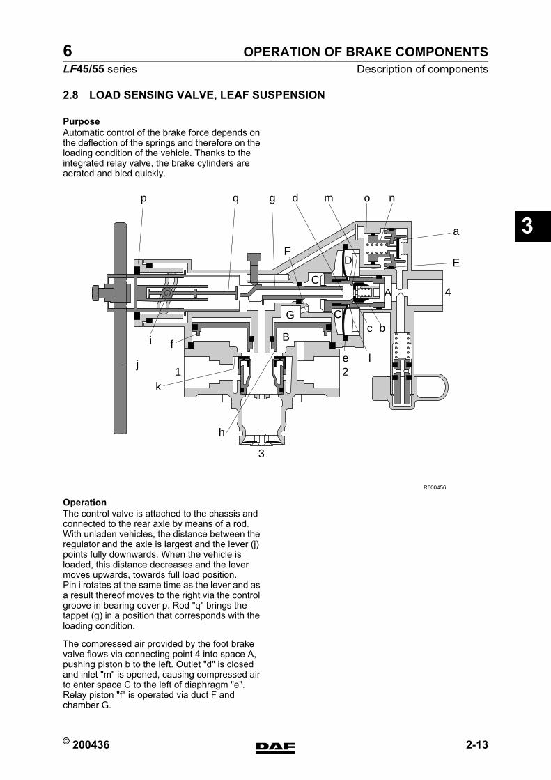
2.8 LOAD SENSING VALVE, LEAF SUSPENSION
PurposeAutomatic control of the brake force depends on the deflection of the springs and therefore on the loading condition of the vehicle. Thanks to the integrated relay valve, the brake cylinders are aerated and bled quickly.
OperationThe control valve is attached to the chassis and connected to the rear axle by means of a rod.With unladen vehicles, the distance between the regulator and the axle is largest and the lever (j) points fully downwards. When the vehicle is loaded, this distance decreases and the lever moves upwards, towards full load position.Pin i rotates at the same time as the lever and as a result thereof moves to the right via the control groove in bearing cover p. Rod "q" brings the tappet (g) in a position that corresponds with the loading condition.
The compressed air provided by the foot brake valve flows via connecting point 4 into space A, pushing piston b to the left. Outlet "d" is closed and inlet "m" is opened, causing compressed air to enter space C to the left of diaphragm "e". Relay piston "f" is operated via duct F and chamber G.
3
21
4
E
C
C
FD
A
G
B
a
nomdgq
j
i fe l
k
p
h
c b
R600456
https://www.truck-manuals.net/
OPERATION OF BRAKE COMPONENTS
2-14 © 200436
Description of components
3
ΛΦ45/55 series6
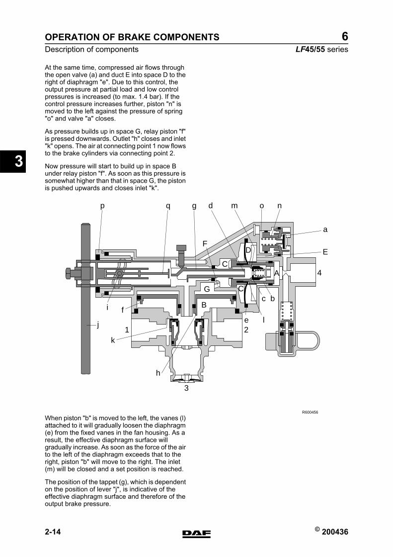
At the same time, compressed air flows through the open valve (a) and duct E into space D to the right of diaphragm "e". Due to this control, the output pressure at partial load and low control pressures is increased (to max. 1.4 bar). If the control pressure increases further, piston "n" is moved to the left against the pressure of spring "o" and valve "a" closes.
As pressure builds up in space G, relay piston "f" is pressed downwards. Outlet "h" closes and inlet "k" opens. The air at connecting point 1 now flows to the brake cylinders via connecting point 2.
Now pressure will start to build up in space B under relay piston "f". As soon as this pressure is somewhat higher than that in space G, the piston is pushed upwards and closes inlet "k".
When piston "b" is moved to the left, the vanes (l) attached to it will gradually loosen the diaphragm (e) from the fixed vanes in the fan housing. As a result, the effective diaphragm surface will gradually increase. As soon as the force of the air to the left of the diaphragm exceeds that to the right, piston "b" will move to the right. The inlet (m) will be closed and a set position is reached.
The position of the tappet (g), which is dependent on the position of lever "j", is indicative of the effective diaphragm surface and therefore of the output brake pressure.
3
21
4
E
C
C
FD
A
G
B
a
nomdgq
j
i fe l
k
p
h
c b
R600456
https://www.truck-manuals.net/
© 200436 2-15
Description of componentsOPERATION OF BRAKE COMPONENTS
ΛΦ45/55 series6
3
The position of the tappet (g) determines to what extent piston "b" must be moved with the vane disc (l) to allow the valve to build up pressure. Due to this movement, the effective surface of the diaphragm will alter.
In full-load position, this surface and that of piston "b" are equally large. The control pressure at connecting point 4 is therefore let through (ratio 1:1) to spaces C and G. The output pressure at 2 will now be equal to the control pressure at connecting point 4.
If the pressure decreases at connecting point 4, piston "b" will be pushed to the right by the pressure in space C. Bleed vent d will open and the pressure in spaces C and G will fall. The relay piston will be pushed up due to the pressure still present in space B, causing bleed vent "h" to open. The pressure at connecting point 2 will now fall via bleed vent 3.
A stop bolt in front of the tappet (g) ensures that this valve can always provide the minimum brake pressure if lever "j" is in too low a position due to a fault. The factory setting of this bolt must not be changed.
https://www.truck-manuals.net/
OPERATION OF BRAKE COMPONENTS
2-16 © 200436
Description of components
3
ΛΦ45/55 series6
2.9 ABS VALVE
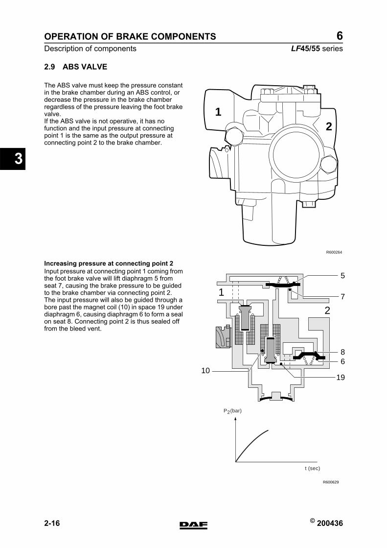
The ABS valve must keep the pressure constant in the brake chamber during an ABS control, or decrease the pressure in the brake chamber regardless of the pressure leaving the foot brake valve.If the ABS valve is not operative, it has no function and the input pressure at connecting point 1 is the same as the output pressure at connecting point 2 to the brake chamber.
Increasing pressure at connecting point 2Input pressure at connecting point 1 coming from the foot brake valve will lift diaphragm 5 from seat 7, causing the brake pressure to be guided to the brake chamber via connecting point 2.The input pressure will also be guided through a bore past the magnet coil (10) in space 19 under diaphragm 6, causing diaphragm 6 to form a seal on seat 8. Connecting point 2 is thus sealed off from the bleed vent.
12
R600264
68
1910
7
5
2
1
R600629
P (bar)
t (sec)
2
https://www.truck-manuals.net/
© 200436 2-17
Description of componentsOPERATION OF BRAKE COMPONENTS
ΛΦ45/55 series6
3
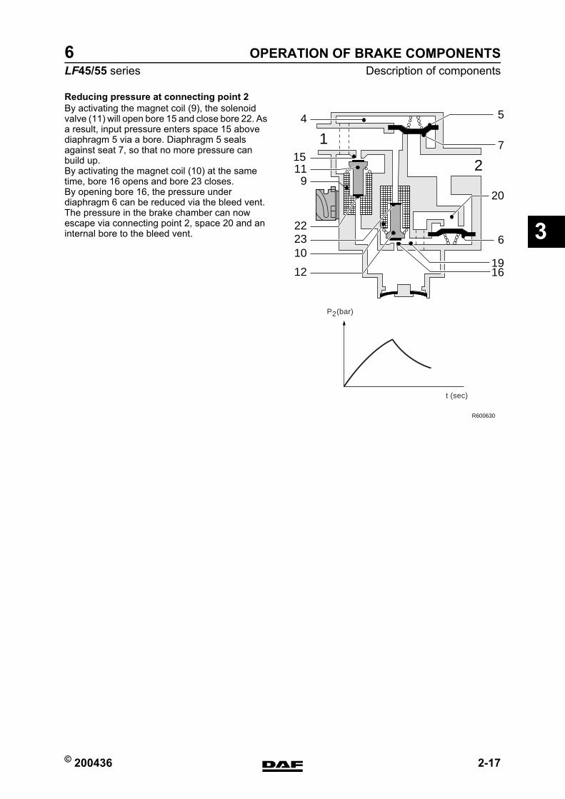
Reducing pressure at connecting point 2By activating the magnet coil (9), the solenoid valve (11) will open bore 15 and close bore 22. As a result, input pressure enters space 15 above diaphragm 5 via a bore. Diaphragm 5 seals against seat 7, so that no more pressure can build up.By activating the magnet coil (10) at the same time, bore 16 opens and bore 23 closes.By opening bore 16, the pressure under diaphragm 6 can be reduced via the bleed vent. The pressure in the brake chamber can now escape via connecting point 2, space 20 and an internal bore to the bleed vent.
6
19
20
16
7
5
10
22
1115
9
12
4
23
2
1
R600630
P (bar)
t (sec)
2
https://www.truck-manuals.net/
OPERATION OF BRAKE COMPONENTS
2-18 © 200436
Description of components
3
ΛΦ45/55 series6
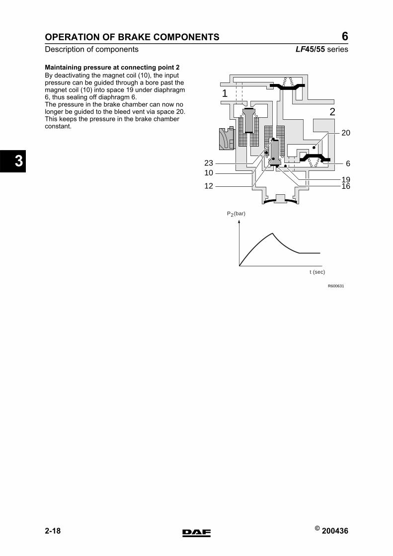
Maintaining pressure at connecting point 2By deactivating the magnet coil (10), the input pressure can be guided through a bore past the magnet coil (10) into space 19 under diaphragm 6, thus sealing off diaphragm 6.The pressure in the brake chamber can now no longer be guided to the bleed vent via space 20.This keeps the pressure in the brake chamber constant.
R600631
2
1
6
20
1916
10
12
23
P (bar)
t (sec)
2
https://www.truck-manuals.net/
© 200436 2-19
Description of componentsOPERATION OF BRAKE COMPONENTS
ΛΦ45/55 series6
3
2.10 TWO-WAY VALVE
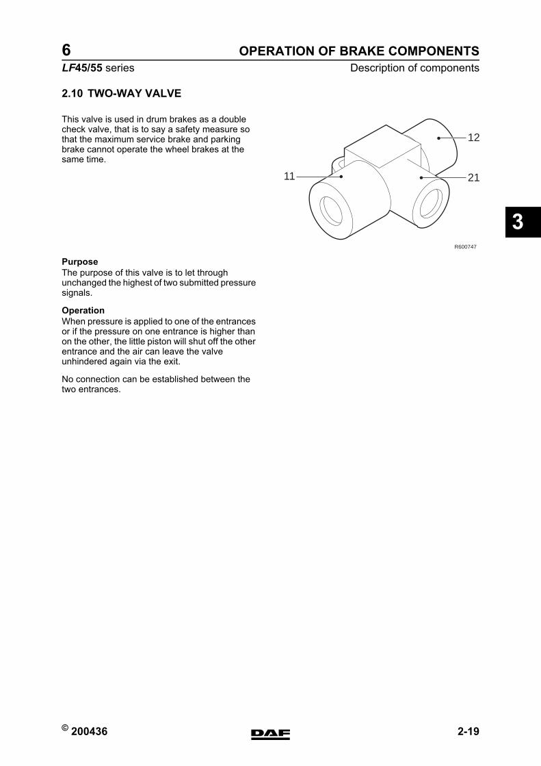
This valve is used in drum brakes as a double check valve, that is to say a safety measure so that the maximum service brake and parking brake cannot operate the wheel brakes at the same time.
PurposeThe purpose of this valve is to let through unchanged the highest of two submitted pressure signals.
OperationWhen pressure is applied to one of the entrances or if the pressure on one entrance is higher than on the other, the little piston will shut off the other entrance and the air can leave the valve unhindered again via the exit.
No connection can be established between the two entrances.
11 21
12
R600747
https://www.truck-manuals.net/
OPERATION OF BRAKE COMPONENTS
2-20 © 200436
Description of components
3
ΛΦ45/55 series6
2.11 ASR SOLENOID VALVE
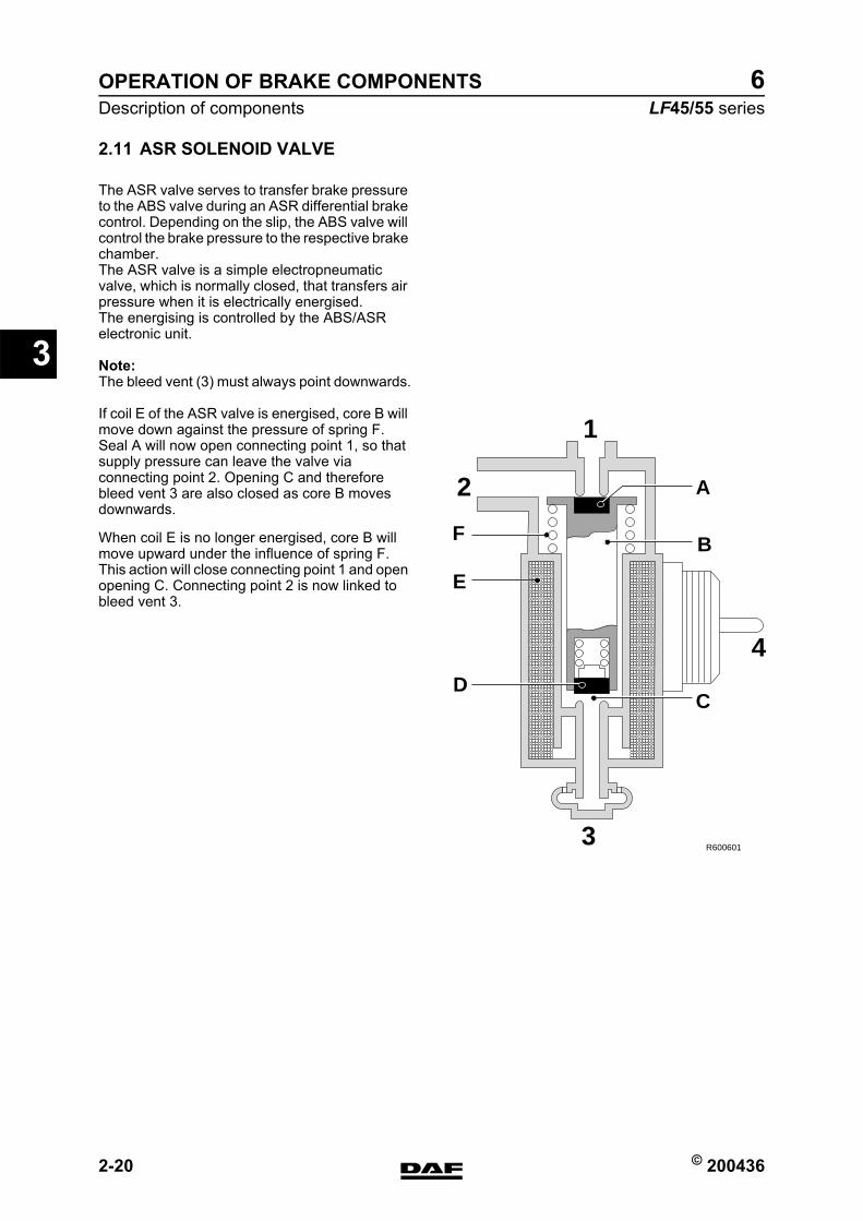
The ASR valve serves to transfer brake pressure to the ABS valve during an ASR differential brake control. Depending on the slip, the ABS valve will control the brake pressure to the respective brake chamber.The ASR valve is a simple electropneumatic valve, which is normally closed, that transfers air pressure when it is electrically energised.The energising is controlled by the ABS/ASR electronic unit.
Note:The bleed vent (3) must always point downwards.
If coil E of the ASR valve is energised, core B will move down against the pressure of spring F.Seal A will now open connecting point 1, so that supply pressure can leave the valve via connecting point 2. Opening C and therefore bleed vent 3 are also closed as core B moves downwards.
When coil E is no longer energised, core B will move upward under the influence of spring F.This action will close connecting point 1 and open opening C. Connecting point 2 is now linked to bleed vent 3.
R600601
2
3
C
B
D
E
F
A
1
4
https://www.truck-manuals.net/

© 200436 2-21
Description of componentsOPERATION OF BRAKE COMPONENTS
ΛΦ45/55 series6
3
2.12 EMERGENCY FILLING/TEST CONNECTION
In various places in the brake system there are test connections for carrying out inspections and adjustments. A pipe leads from point 24 of the air dryer to the rear left of the cab. There is a test connection here that can be used as an emergency/tyre filling connection.
Note:With a leaf-spring front axle this test connection is on point 11 of the air dryer.If a pipe is connected to the test connection, screwing in the union will lift the spring-loaded valve (A) from its seat, opening the supply. If the union is removed, the valve is pushed onto its seat by spring B, closing the supply.
A
B
R600495
https://www.truck-manuals.net/
OPERATION OF BRAKE COMPONENTS
2-22 © 200436
Description of components
3
ΛΦ45/55 series6
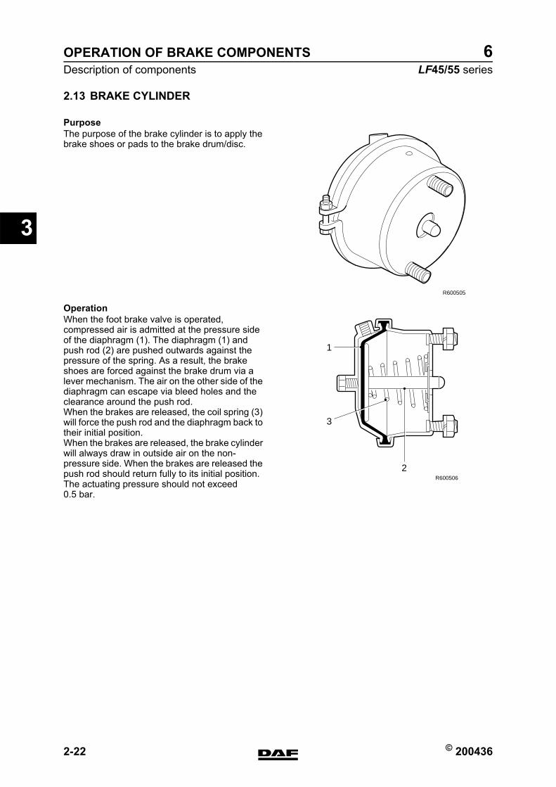
2.13 BRAKE CYLINDER
PurposeThe purpose of the brake cylinder is to apply the brake shoes or pads to the brake drum/disc.
OperationWhen the foot brake valve is operated, compressed air is admitted at the pressure side of the diaphragm (1). The diaphragm (1) and push rod (2) are pushed outwards against the pressure of the spring. As a result, the brake shoes are forced against the brake drum via a lever mechanism. The air on the other side of the diaphragm can escape via bleed holes and the clearance around the push rod.When the brakes are released, the coil spring (3) will force the push rod and the diaphragm back to their initial position.When the brakes are released, the brake cylinder will always draw in outside air on the non-pressure side. When the brakes are released the push rod should return fully to its initial position. The actuating pressure should not exceed 0.5 bar.
R600505
2
1
3
R600506
https://www.truck-manuals.net/
© 200436 2-23
Description of componentsOPERATION OF BRAKE COMPONENTS
ΛΦ45/55 series6
3
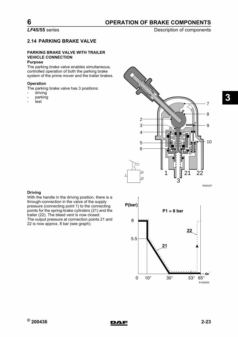
2.14 PARKING BRAKE VALVE
PARKING BRAKE VALVE WITH TRAILER VEHICLE CONNECTIONPurposeThe parking brake valve enables simultaneous, controlled operation of both the parking brake system of the prime mover and the trailer brakes.
OperationThe parking brake valve has 3 positions:- driving- parking- test
DrivingWith the handle in the driving position, there is a through-connection in the valve of the supply pressure (connecting point 1) to the connecting points for the spring-brake cylinders (21) and the trailer (22). The bleed vent is now closed.The output pressure at connection points 21 and 22 is now approx. 8 bar (see graph).
3211 22
23
5
4
6
8
7
9
10
R600397
121
22
https://www.truck-manuals.net/
OPERATION OF BRAKE COMPONENTS
2-24 © 200436
Description of components
3
ΛΦ45/55 series6
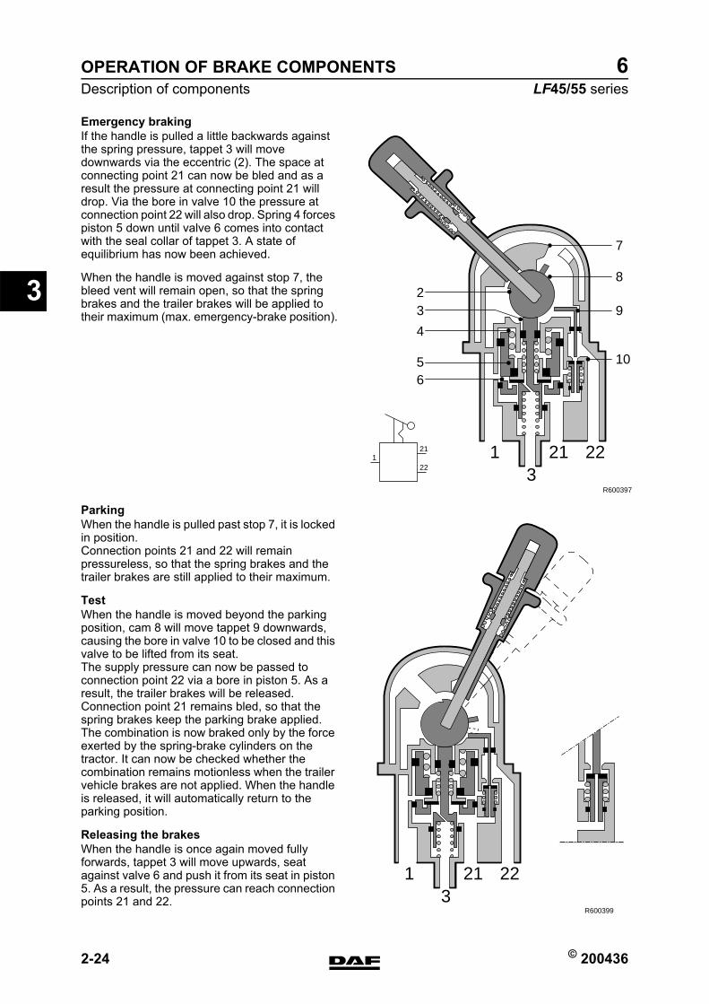
Emergency brakingIf the handle is pulled a little backwards against the spring pressure, tappet 3 will move downwards via the eccentric (2). The space at connecting point 21 can now be bled and as a result the pressure at connecting point 21 will drop. Via the bore in valve 10 the pressure at connection point 22 will also drop. Spring 4 forces piston 5 down until valve 6 comes into contact with the seal collar of tappet 3. A state of equilibrium has now been achieved.
When the handle is moved against stop 7, the bleed vent will remain open, so that the spring brakes and the trailer brakes will be applied to their maximum (max. emergency-brake position).
ParkingWhen the handle is pulled past stop 7, it is locked in position.Connection points 21 and 22 will remain pressureless, so that the spring brakes and the trailer brakes are still applied to their maximum.
TestWhen the handle is moved beyond the parking position, cam 8 will move tappet 9 downwards, causing the bore in valve 10 to be closed and this valve to be lifted from its seat.The supply pressure can now be passed to connection point 22 via a bore in piston 5. As a result, the trailer brakes will be released. Connection point 21 remains bled, so that the spring brakes keep the parking brake applied.The combination is now braked only by the force exerted by the spring-brake cylinders on the tractor. It can now be checked whether the combination remains motionless when the trailer vehicle brakes are not applied. When the handle is released, it will automatically return to the parking position.
Releasing the brakesWhen the handle is once again moved fully forwards, tappet 3 will move upwards, seat against valve 6 and push it from its seat in piston 5. As a result, the pressure can reach connection points 21 and 22.
3211 22
23
5
4
6
8
7
9
10
R600397
121
22
3211 22
R600399
https://www.truck-manuals.net/
© 200436 2-25
Description of componentsOPERATION OF BRAKE COMPONENTS
ΛΦ45/55 series6
3
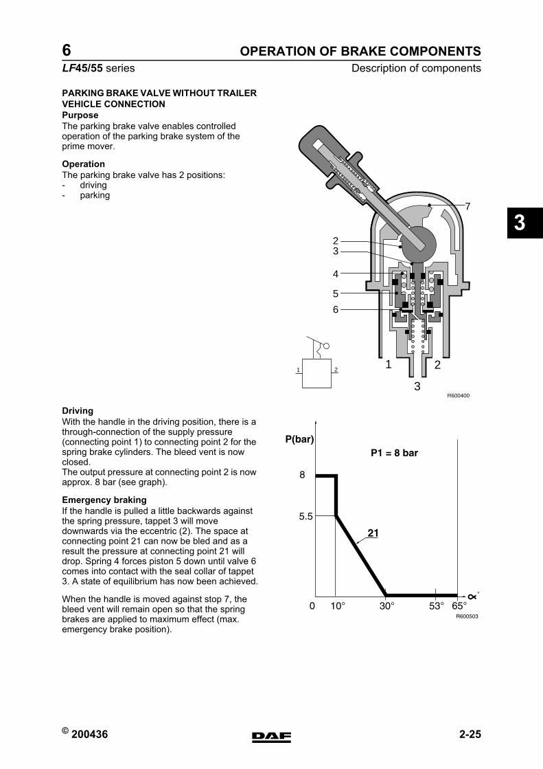
PARKING BRAKE VALVE WITHOUT TRAILER VEHICLE CONNECTIONPurposeThe parking brake valve enables controlled operation of the parking brake system of the prime mover.
OperationThe parking brake valve has 2 positions:- driving- parking
DrivingWith the handle in the driving position, there is a through-connection of the supply pressure (connecting point 1) to connecting point 2 for the spring brake cylinders. The bleed vent is now closed.The output pressure at connecting point 2 is now approx. 8 bar (see graph).
Emergency brakingIf the handle is pulled a little backwards against the spring pressure, tappet 3 will move downwards via the eccentric (2). The space at connecting point 21 can now be bled and as a result the pressure at connecting point 21 will drop. Spring 4 forces piston 5 down until valve 6 comes into contact with the seal collar of tappet 3. A state of equilibrium has now been achieved.
When the handle is moved against stop 7, the bleed vent will remain open so that the spring brakes are applied to maximum effect (max. emergency brake position).
R600400
2
7
3
4
5
6
1
3
21 2
https://www.truck-manuals.net/
OPERATION OF BRAKE COMPONENTS
2-26 © 200436
Description of components
3
ΛΦ45/55 series6
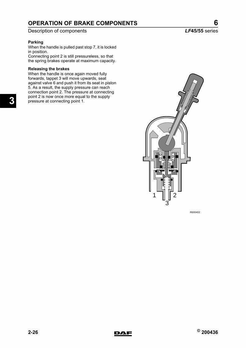
ParkingWhen the handle is pulled past stop 7, it is locked in position.Connecting point 2 is still pressureless, so that the spring brakes operate at maximum capacity.
Releasing the brakesWhen the handle is once again moved fully forwards, tappet 3 will move upwards, seat against valve 6 and push it from its seat in piston 5. As a result, the supply pressure can reach connection point 2. The pressure at connecting point 2 is now once more equal to the supply pressure at connecting point 1.
321
R600402
https://www.truck-manuals.net/
© 200436 2-27
Description of componentsOPERATION OF BRAKE COMPONENTS
ΛΦ45/55 series6
3
2.15 SPRING BRAKE CYLINDER
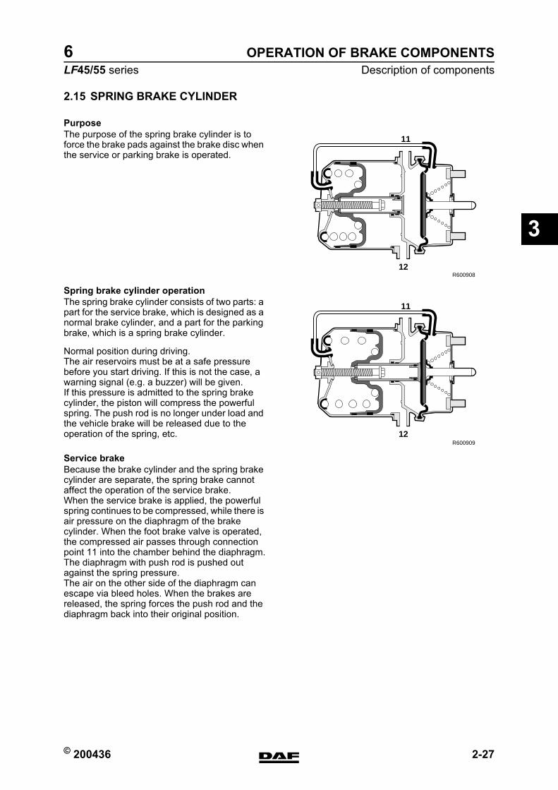
PurposeThe purpose of the spring brake cylinder is to force the brake pads against the brake disc when the service or parking brake is operated.
Spring brake cylinder operationThe spring brake cylinder consists of two parts: a part for the service brake, which is designed as a normal brake cylinder, and a part for the parking brake, which is a spring brake cylinder.
Normal position during driving.The air reservoirs must be at a safe pressure before you start driving. If this is not the case, a warning signal (e.g. a buzzer) will be given.If this pressure is admitted to the spring brake cylinder, the piston will compress the powerful spring. The push rod is no longer under load and the vehicle brake will be released due to the operation of the spring, etc.
Service brakeBecause the brake cylinder and the spring brake cylinder are separate, the spring brake cannot affect the operation of the service brake.When the service brake is applied, the powerful spring continues to be compressed, while there is air pressure on the diaphragm of the brake cylinder. When the foot brake valve is operated, the compressed air passes through connection point 11 into the chamber behind the diaphragm.The diaphragm with push rod is pushed out against the spring pressure.The air on the other side of the diaphragm can escape via bleed holes. When the brakes are released, the spring forces the push rod and the diaphragm back into their original position.
11
12R600908
11
12R600909
https://www.truck-manuals.net/
OPERATION OF BRAKE COMPONENTS
2-28 © 200436
Description of components
3
ΛΦ45/55 series6
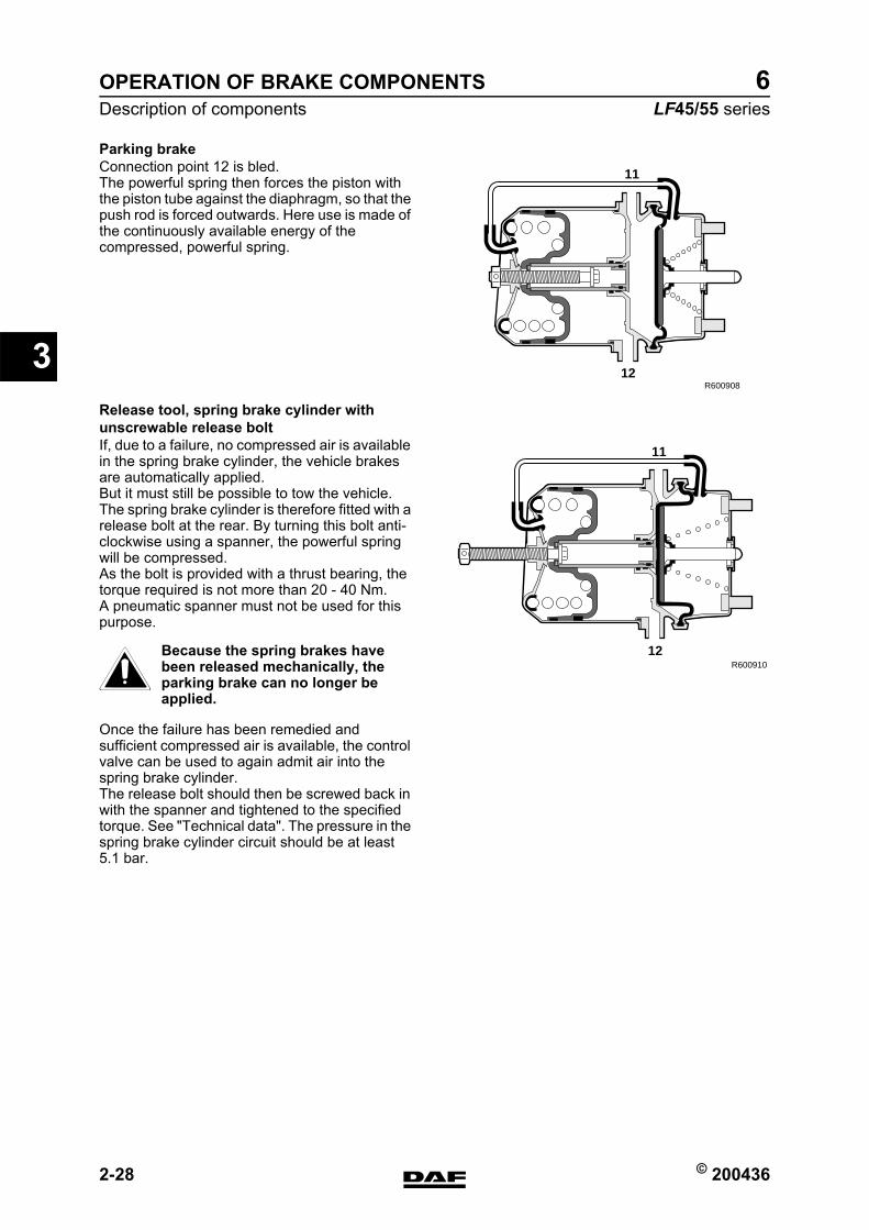
Parking brakeConnection point 12 is bled.The powerful spring then forces the piston with the piston tube against the diaphragm, so that the push rod is forced outwards. Here use is made of the continuously available energy of the compressed, powerful spring.
Release tool, spring brake cylinder with unscrewable release boltIf, due to a failure, no compressed air is available in the spring brake cylinder, the vehicle brakes are automatically applied.But it must still be possible to tow the vehicle.The spring brake cylinder is therefore fitted with a release bolt at the rear. By turning this bolt anti-clockwise using a spanner, the powerful spring will be compressed.As the bolt is provided with a thrust bearing, the torque required is not more than 20 - 40 Nm.A pneumatic spanner must not be used for this purpose.
Because the spring brakes have been released mechanically, the parking brake can no longer be applied.
Once the failure has been remedied and sufficient compressed air is available, the control valve can be used to again admit air into the spring brake cylinder.The release bolt should then be screwed back in with the spanner and tightened to the specified torque. See "Technical data". The pressure in the spring brake cylinder circuit should be at least 5.1 bar.
11
12R600908
11
12R600910}
https://www.truck-manuals.net/
© 200436 2-29
Description of componentsOPERATION OF BRAKE COMPONENTS
ΛΦ45/55 series6
3
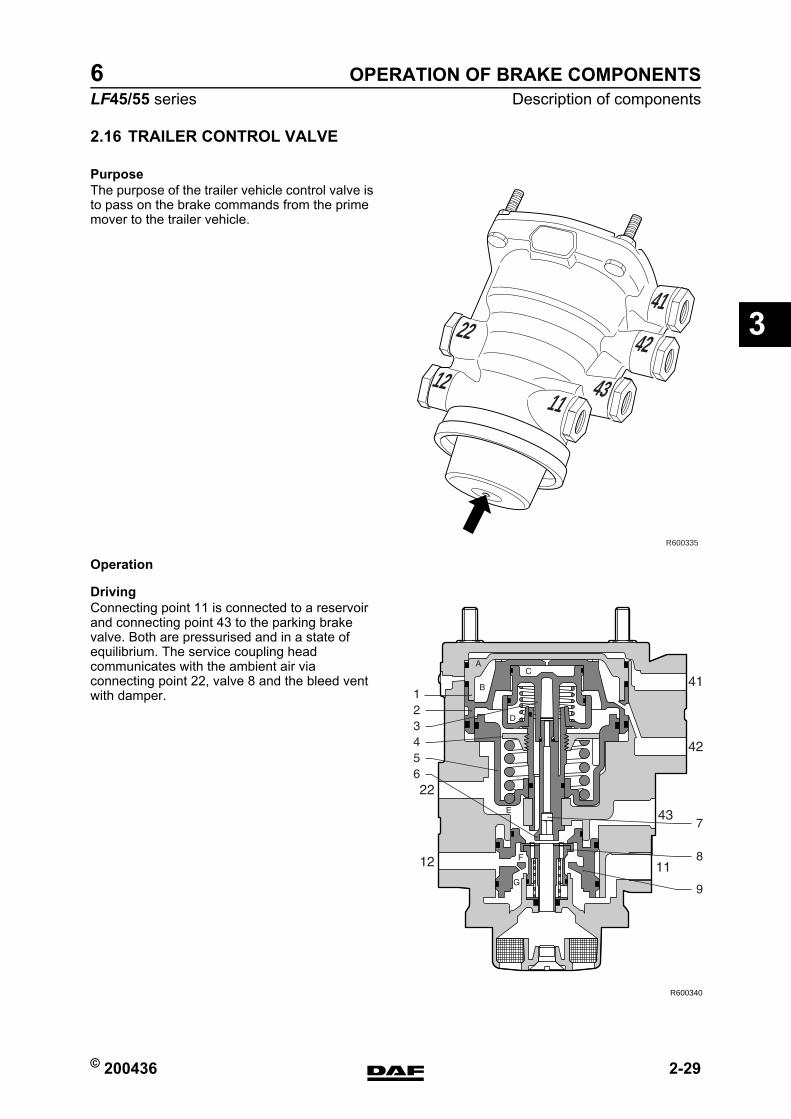
2.16 TRAILER CONTROL VALVE
PurposeThe purpose of the trailer vehicle control valve is to pass on the brake commands from the prime mover to the trailer vehicle.
Operation
DrivingConnecting point 11 is connected to a reservoir and connecting point 43 to the parking brake valve. Both are pressurised and in a state of equilibrium. The service coupling head communicates with the ambient air via connecting point 22, valve 8 and the bleed vent with damper.
41
42
431112
22
R600335
R600340
https://www.truck-manuals.net/
OPERATION OF BRAKE COMPONENTS
2-30 © 200436
Description of components
3
ΛΦ45/55 series6
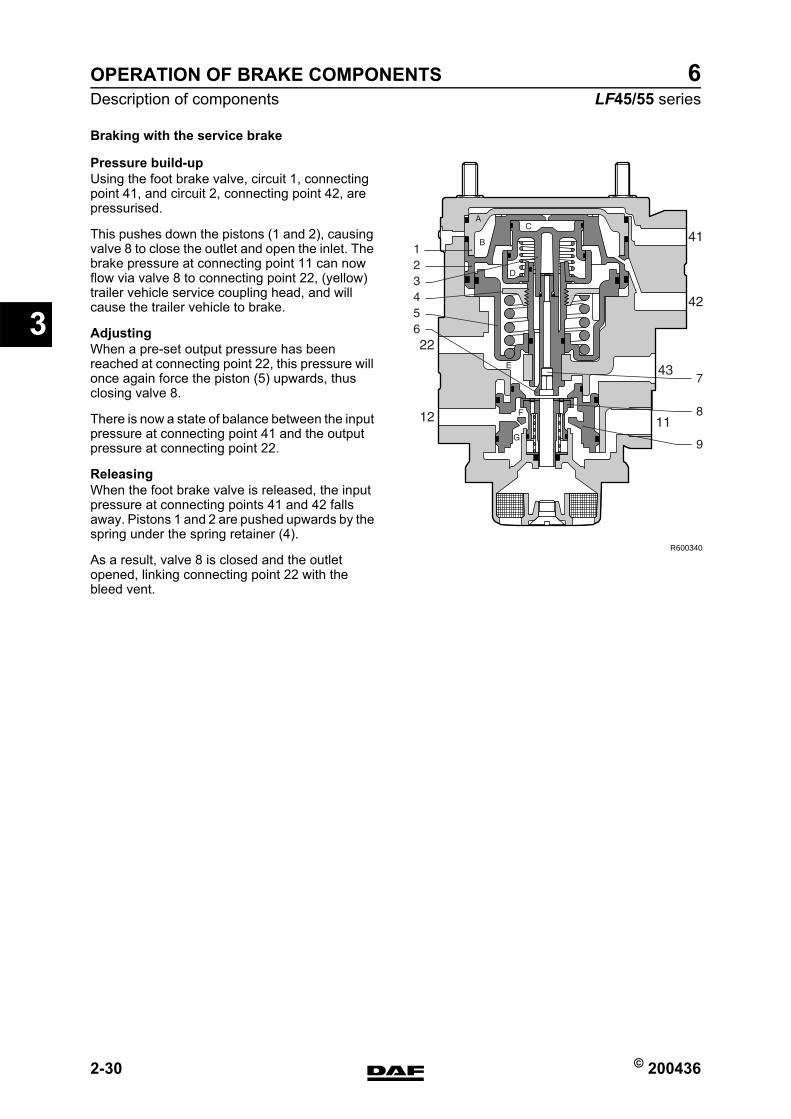
Braking with the service brake
Pressure build-upUsing the foot brake valve, circuit 1, connecting point 41, and circuit 2, connecting point 42, are pressurised.
This pushes down the pistons (1 and 2), causing valve 8 to close the outlet and open the inlet. The brake pressure at connecting point 11 can now flow via valve 8 to connecting point 22, (yellow) trailer vehicle service coupling head, and will cause the trailer vehicle to brake.
AdjustingWhen a pre-set output pressure has been reached at connecting point 22, this pressure will once again force the piston (5) upwards, thus closing valve 8.
There is now a state of balance between the input pressure at connecting point 41 and the output pressure at connecting point 22.
ReleasingWhen the foot brake valve is released, the input pressure at connecting points 41 and 42 falls away. Pistons 1 and 2 are pushed upwards by the spring under the spring retainer (4).
As a result, valve 8 is closed and the outlet opened, linking connecting point 22 with the bleed vent.
R600340
https://www.truck-manuals.net/
© 200436 2-31
Description of componentsOPERATION OF BRAKE COMPONENTS
ΛΦ45/55 series6
3
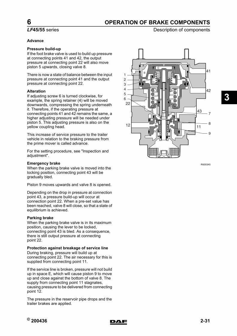
Advance
Pressure build-upIf the foot brake valve is used to build up pressure at connecting points 41 and 42, the output pressure at connecting point 22 will also move piston 5 upwards, closing valve 8.
There is now a state of balance between the input pressure at connecting point 41 and the output pressure at connecting point 22.
AlterationIf adjusting screw 6 is turned clockwise, for example, the spring retainer (4) will be moved downwards, compressing the spring underneath it. Therefore, if the operating pressure at connecting points 41 and 42 remains the same, a higher adjusting pressure will be needed under piston 5. This adjusting pressure is also on the yellow coupling head.
This increase of service pressure to the trailer vehicle in relation to the braking pressure from the prime mover is called advance.
For the setting procedure, see "Inspection and adjustment".
Emergency brakeWhen the parking brake valve is moved into the locking position, connecting point 43 will be gradually bled.
Piston 9 moves upwards and valve 8 is opened.
Depending on the drop in pressure at connection point 43, a pressure build-up will occur at connection point 22. When a pre-set value has been reached, valve 8 will close, so that a state of equilibrium is achieved.
Parking brakeWhen the parking brake valve is in its maximum position, causing the lever to be locked, connecting point 43 is bled. As a consequence, there is still output pressure at connecting point 22.
Protection against breakage of service lineDuring braking, pressure will build up at connecting point 22. The air necessary for this is supplied from connecting point 11.
If the service line is broken, pressure will not build up in space E, which will cause piston 9 to move up and close against the bottom of valve 8. The supply from connecting point 11 stagnates, causing pressure to be delivered from connecting point 12.
The pressure in the reservoir pipe drops and the trailer brakes are applied.
R600340
https://www.truck-manuals.net/
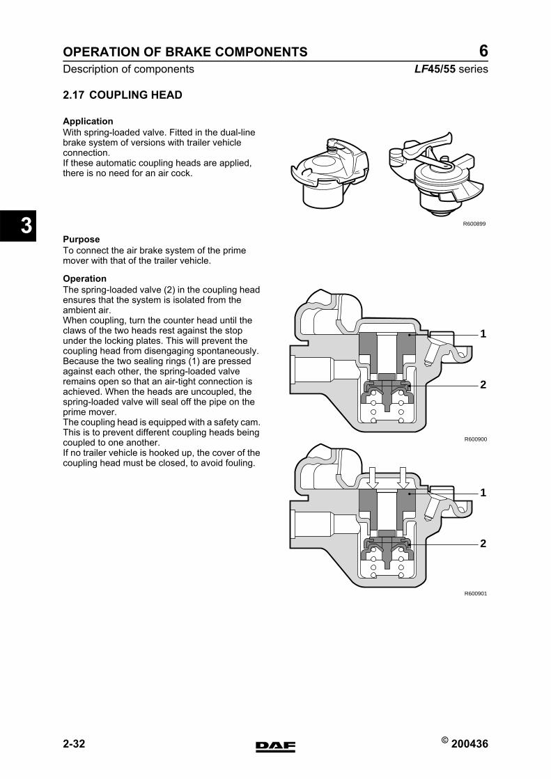
OPERATION OF BRAKE COMPONENTS
2-32 © 200436
Description of components
3
ΛΦ45/55 series6
2.17 COUPLING HEAD
ApplicationWith spring-loaded valve. Fitted in the dual-line brake system of versions with trailer vehicle connection.If these automatic coupling heads are applied, there is no need for an air cock.
PurposeTo connect the air brake system of the prime mover with that of the trailer vehicle.
OperationThe spring-loaded valve (2) in the coupling head ensures that the system is isolated from the ambient air.When coupling, turn the counter head until the claws of the two heads rest against the stop under the locking plates. This will prevent the coupling head from disengaging spontaneously.Because the two sealing rings (1) are pressed against each other, the spring-loaded valve remains open so that an air-tight connection is achieved. When the heads are uncoupled, the spring-loaded valve will seal off the pipe on the prime mover.The coupling head is equipped with a safety cam. This is to prevent different coupling heads being coupled to one another.If no trailer vehicle is hooked up, the cover of the coupling head must be closed, to avoid fouling.
R600899
R600900
2
1
R600901
2
1
https://www.truck-manuals.net/
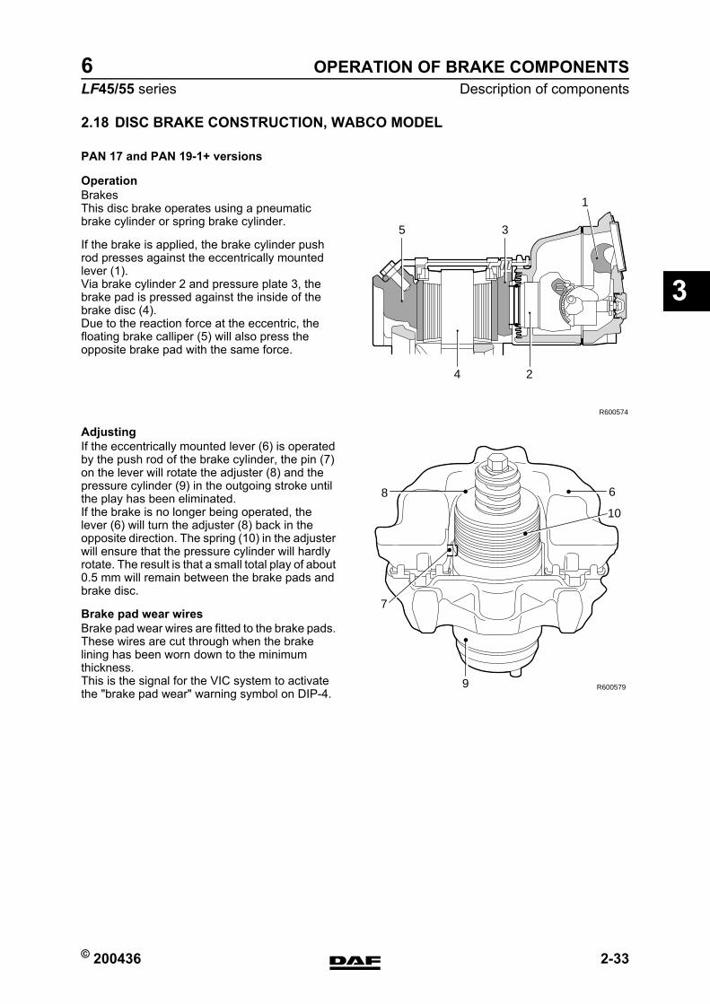
© 200436 2-33
Description of componentsOPERATION OF BRAKE COMPONENTS
ΛΦ45/55 series6
3
2.18 DISC BRAKE CONSTRUCTION, WABCO MODEL
PAN 17 and PAN 19-1+ versions
OperationBrakesThis disc brake operates using a pneumatic brake cylinder or spring brake cylinder.
If the brake is applied, the brake cylinder push rod presses against the eccentrically mounted lever (1).Via brake cylinder 2 and pressure plate 3, the brake pad is pressed against the inside of the brake disc (4).Due to the reaction force at the eccentric, the floating brake calliper (5) will also press the opposite brake pad with the same force.
AdjustingIf the eccentrically mounted lever (6) is operated by the push rod of the brake cylinder, the pin (7) on the lever will rotate the adjuster (8) and the pressure cylinder (9) in the outgoing stroke until the play has been eliminated.If the brake is no longer being operated, the lever (6) will turn the adjuster (8) back in the opposite direction. The spring (10) in the adjuster will ensure that the pressure cylinder will hardly rotate. The result is that a small total play of about 0.5 mm will remain between the brake pads and brake disc.
Brake pad wear wiresBrake pad wear wires are fitted to the brake pads. These wires are cut through when the brake lining has been worn down to the minimum thickness.This is the signal for the VIC system to activate the "brake pad wear" warning symbol on DIP-4.
R600573
R600574
1
35
4 2
R6005799
7
8 6
10
https://www.truck-manuals.net/
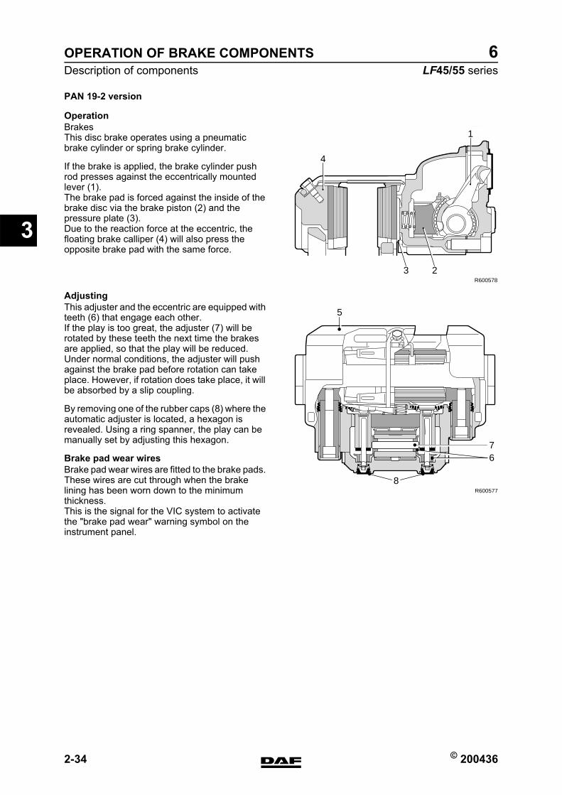
OPERATION OF BRAKE COMPONENTS
2-34 © 200436
Description of components
3
ΛΦ45/55 series6
PAN 19-2 version
OperationBrakesThis disc brake operates using a pneumatic brake cylinder or spring brake cylinder.
If the brake is applied, the brake cylinder push rod presses against the eccentrically mounted lever (1).The brake pad is forced against the inside of the brake disc via the brake piston (2) and the pressure plate (3).Due to the reaction force at the eccentric, the floating brake calliper (4) will also press the opposite brake pad with the same force.
AdjustingThis adjuster and the eccentric are equipped with teeth (6) that engage each other.If the play is too great, the adjuster (7) will be rotated by these teeth the next time the brakes are applied, so that the play will be reduced.Under normal conditions, the adjuster will push against the brake pad before rotation can take place. However, if rotation does take place, it will be absorbed by a slip coupling.
By removing one of the rubber caps (8) where the automatic adjuster is located, a hexagon is revealed. Using a ring spanner, the play can be manually set by adjusting this hexagon.
Brake pad wear wiresBrake pad wear wires are fitted to the brake pads. These wires are cut through when the brake lining has been worn down to the minimum thickness.This is the signal for the VIC system to activate the "brake pad wear" warning symbol on the instrument panel.
R600578
3
4
1
2
R600577
67
8
5
https://www.truck-manuals.net/
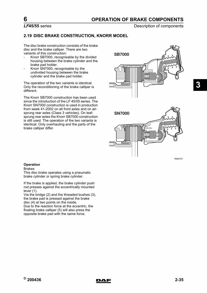
© 200436 2-35
Description of componentsOPERATION OF BRAKE COMPONENTS
ΛΦ45/55 series6
3
2.19 DISC BRAKE CONSTRUCTION, KNORR MODEL
The disc brake construction consists of the brake disc and the brake calliper. There are two variants of this construction:- Knorr SB7000, recognisable by the divided
housing between the brake cylinder and the brake pad holder.
- Knorr SN7000, recognisable by the undivided housing between the brake cylinder and the brake pad holder.
The operation of the two variants is identical. Only the reconditioning of the brake calliper is different.
The Knorr SB7000 construction has been used since the introduction of the LF 45/55 series. The Knorr SN7000 construction is used in production from week 41-2002 on all front axles and on air-sprung rear axles (Class 3 vehicles). On leaf-sprung rear axles the Knorr SB7000 construction is still used. The operation of the two variants is identical. Only overhauling and the parts of the brake calliper differ.
OperationBrakesThis disc brake operates using a pneumatic brake cylinder or spring brake cylinder.
If the brake is applied, the brake cylinder push rod presses against the eccentrically mounted lever (1).Via the bridge (2) and the threaded bushes (3), the brake pad is pressed against the brake disc (4) at two points on the inside.Due to the reaction force at the eccentric, the floating brake calliper (5) will also press the opposite brake pad with the same force.
R600707
SB7000
SN7000
https://www.truck-manuals.net/
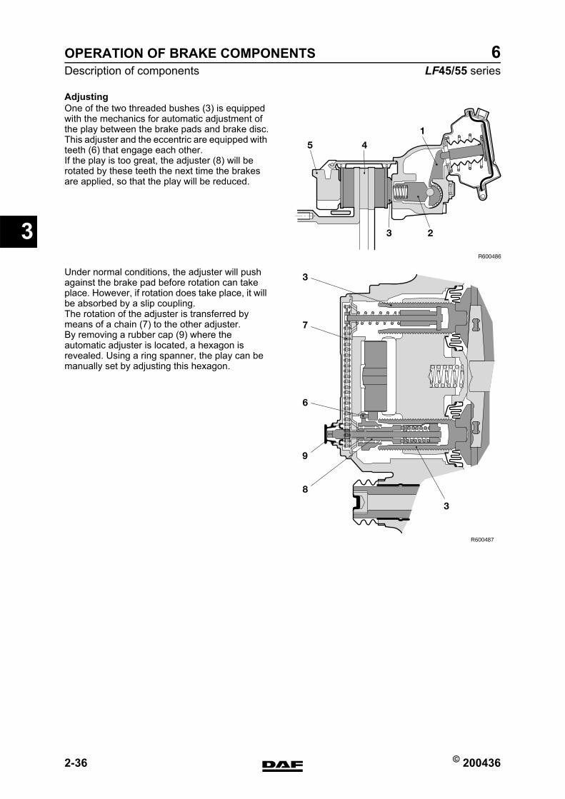
OPERATION OF BRAKE COMPONENTS
2-36 © 200436
Description of components
3
ΛΦ45/55 series6
AdjustingOne of the two threaded bushes (3) is equipped with the mechanics for automatic adjustment of the play between the brake pads and brake disc.This adjuster and the eccentric are equipped with teeth (6) that engage each other.If the play is too great, the adjuster (8) will be rotated by these teeth the next time the brakes are applied, so that the play will be reduced.
Under normal conditions, the adjuster will push against the brake pad before rotation can take place. However, if rotation does take place, it will be absorbed by a slip coupling.The rotation of the adjuster is transferred by means of a chain (7) to the other adjuster.By removing a rubber cap (9) where the automatic adjuster is located, a hexagon is revealed. Using a ring spanner, the play can be manually set by adjusting this hexagon.
45
1
3 2
R600486
R600487
3
7
6
8
3
9
https://www.truck-manuals.net/
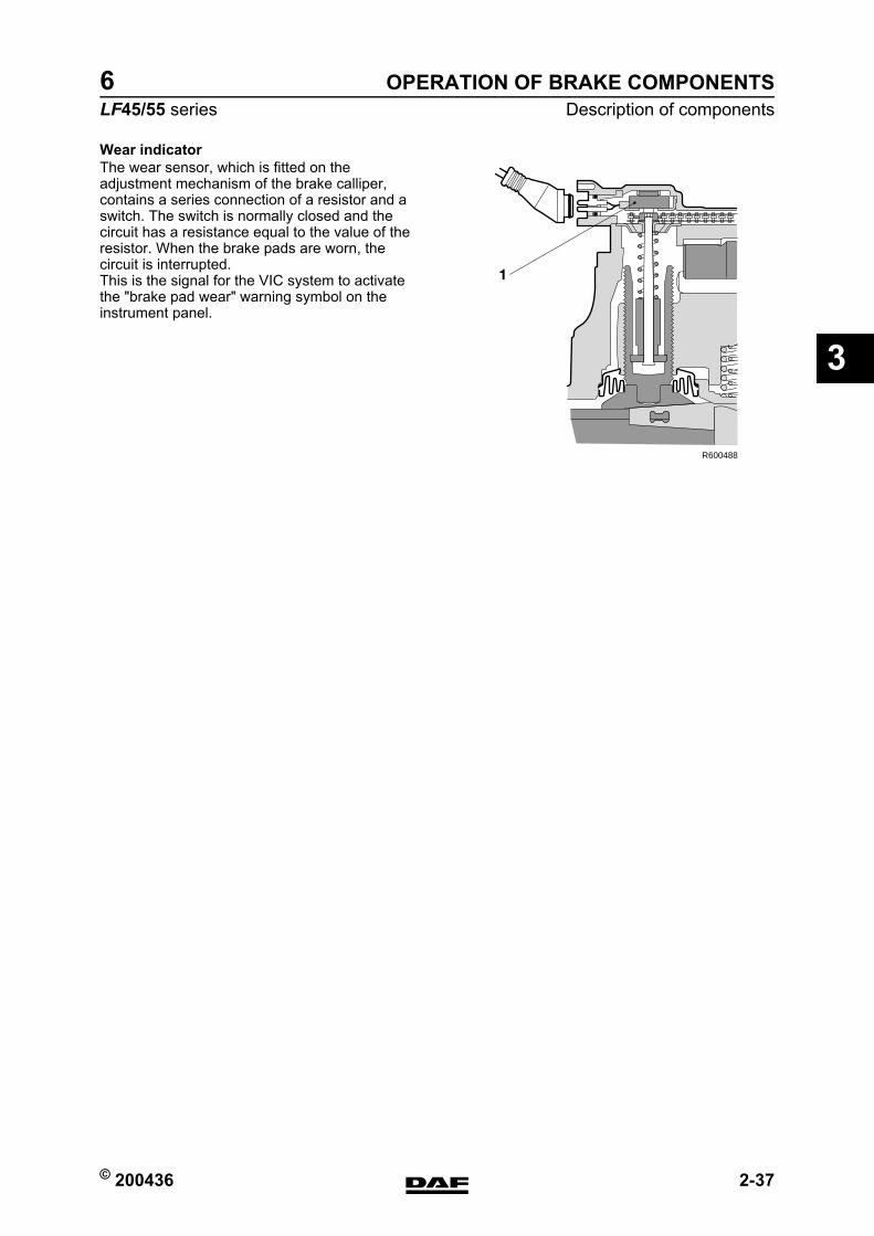
© 200436 2-37
Description of componentsOPERATION OF BRAKE COMPONENTS
ΛΦ45/55 series6
3
Wear indicatorThe wear sensor, which is fitted on the adjustment mechanism of the brake calliper, contains a series connection of a resistor and a switch. The switch is normally closed and the circuit has a resistance equal to the value of the resistor. When the brake pads are worn, the circuit is interrupted.This is the signal for the VIC system to activate the "brake pad wear" warning symbol on the instrument panel.
1
R600488
https://www.truck-manuals.net/
OPERATION OF BRAKE COMPONENTS
2-38 © 200436
Description of components
3
ΛΦ45/55 series6
https://www.truck-manuals.net/
© 200436 1
ContentsBRAKE SYSTEM AND COMPONENTS
ΛΦ45/55 series6
4
4 Brake system and componentsCONTENTSPage Date
1. SAFETY INSTRUCTIONS. . . . . . . . . . . . . . . . . . . . . . . . . . . . . . . . . . . . . . . . . . 1-1 . . . . . 2004361.1 Safety instructions . . . . . . . . . . . . . . . . . . . . . . . . . . . . . . . . . . . . . . . . . . . 1-1 . . . . . 200436
2. INSPECTION AND ADJUSTMENT. . . . . . . . . . . . . . . . . . . . . . . . . . . . . . . . . . . 2-1 . . . . . 2004362.1 Inspection, compressor capacity . . . . . . . . . . . . . . . . . . . . . . . . . . . . . . . . 2-1 . . . . . 2004362.2 Inspection, foot brake valve. . . . . . . . . . . . . . . . . . . . . . . . . . . . . . . . . . . . 2-2 . . . . . 2004362.3 Inspection and adjustment, load sensing valve, air suspension . . . . . . . . 2-3 . . . . . 2004362.4 Inspection and adjustment, load sensing valve, leaf suspension . . . . . . . 2-5 . . . . . 2004362.5 Inspection empty/load relay valve . . . . . . . . . . . . . . . . . . . . . . . . . . . . . . . 2-7 . . . . . 2004362.6 Inspecting the relay valve . . . . . . . . . . . . . . . . . . . . . . . . . . . . . . . . . . . . . 2-9 . . . . . 2004362.7 Inspection, trailer vehicle control valve . . . . . . . . . . . . . . . . . . . . . . . . . . . 2-10 . . . . 2004362.8 Inspection and adjustment, advance in trailer vehicle control valve . . . . . 2-11 . . . . 2004362.9 Inspection, parking brake valve . . . . . . . . . . . . . . . . . . . . . . . . . . . . . . . . . 2-13 . . . . 2004362.10 Check and adjust input and output pressures of the air supply unit . . . . . 2-15 . . . . 2004362.11 Check air dryer regeneration function in the air supply unit. . . . . . . . . . . . 2-16 . . . . 2004362.12 Check the 4-circuit security valve of the air supply unit . . . . . . . . . . . . . . . 2-17 . . . . 2004362.13 Inspecting brake pads, Wabco model . . . . . . . . . . . . . . . . . . . . . . . . . . . . 2-19 . . . . 2004362.14 Inspecting brake pads, Knorr model . . . . . . . . . . . . . . . . . . . . . . . . . . . . . 2-20 . . . . 2004362.15 inspection, brake discs . . . . . . . . . . . . . . . . . . . . . . . . . . . . . . . . . . . . . . . 2-22 . . . . 2004362.16 Checking automatic disc brake slack adjuster, Wabco model. . . . . . . . . . 2-23 . . . . 2004362.17 Checking automatic disc brake slack adjuster, Knorr model . . . . . . . . . . . 2-24 . . . . 2004362.18 Inspecting brake calliper play, Knorr model. . . . . . . . . . . . . . . . . . . . . . . . 2-25 . . . . 2004362.19 Brake adjustment, disc brake version . . . . . . . . . . . . . . . . . . . . . . . . . . . . 2-27 . . . . 2004362.20 Inspection, air tightness. . . . . . . . . . . . . . . . . . . . . . . . . . . . . . . . . . . . . . . 2-28 . . . . 200436
3. REMOVAL AND INSTALLATION. . . . . . . . . . . . . . . . . . . . . . . . . . . . . . . . . . . . 3-1 . . . . . 2004363.1 Removal and installation, quick-release coupling . . . . . . . . . . . . . . . . . . . 3-1 . . . . . 2004363.2 Removal and installation, pipe on quick-release coupling . . . . . . . . . . . . . 3-2 . . . . . 2004363.3 Removal and installation, brake cylinder . . . . . . . . . . . . . . . . . . . . . . . . . . 3-3 . . . . . 2004363.4 Removal and installation, spring brake cylinder . . . . . . . . . . . . . . . . . . . . 3-4 . . . . . 2004363.5 Removal and installation, compressor cylinder head gasket. . . . . . . . . . . 3-5 . . . . . 2004363.6 Removal and installation, air dryer filter element. . . . . . . . . . . . . . . . . . . . 3-6 . . . . . 2004363.7 Removal and installation, brake pads, Wabco model . . . . . . . . . . . . . . . . 3-8 . . . . . 2004363.8 Removal and installation, brake pads, Knorr model . . . . . . . . . . . . . . . . . 3-13 . . . . 2004363.9 Removal and installation, brake disc, Wabco model . . . . . . . . . . . . . . . . . 3-15 . . . . 2004363.10 Removal and installation, brake disc, Knorr model . . . . . . . . . . . . . . . . . . 3-16 . . . . 2004363.11 Removal and installation, brake calliper, Wabco model . . . . . . . . . . . . . . 3-17 . . . . 2004363.12 Removal and installation, brake calliper, Knorr SB7000 version . . . . . . . . 3-18 . . . . 2004363.13 Removal and installation, brake calliper, Knorr SN7000 version. . . . . . . . 3-20 . . . . 2004363.14 Removal and installation, brake calliper carrier . . . . . . . . . . . . . . . . . . . . . 3-23 . . . . 2004363.15 Removing and installing thrust piece bellows, Wabco model . . . . . . . . . . 3-24 . . . . 2004363.16 Removing and installing bellows with brake calliper thrust piece, Knorr
SB7000 version . . . . . . . . . . . . . . . . . . . . . . . . . . . . . . . . . . . . . . . . . . . . . 3-27 . . . . 2004363.17 Removing and installing bellows with brake calliper thrust piece, Knorr
SN7000 version . . . . . . . . . . . . . . . . . . . . . . . . . . . . . . . . . . . . . . . . . . . . . 3-29 . . . . 2004363.18 Removal and installation, bearing bushes, Wabco model . . . . . . . . . . . . . 3-34 . . . . 2004363.19 Removing and installing brass bearing bush of brake calliper, Knorr
SB7000 version . . . . . . . . . . . . . . . . . . . . . . . . . . . . . . . . . . . . . . . . . . . . . 3-37 . . . . 2004363.20 Removing and installing brass bearing bush of brake calliper, Knorr
SN7000 version . . . . . . . . . . . . . . . . . . . . . . . . . . . . . . . . . . . . . . . . . . . . . 3-39 . . . . 2004363.21 Removing and installing rubber bearing bush of brake calliper, Knorr
SB7000 version . . . . . . . . . . . . . . . . . . . . . . . . . . . . . . . . . . . . . . . . . . . . . 3-42 . . . . 200436
https://www.truck-manuals.net/
BRAKE SYSTEM AND COMPONENTS
2 © 200436
Contents
4
ΛΦ45/55 series6
3.22 Removing and installing rubber bearing bush of brake calliper, Knorr SN7000 version . . . . . . . . . . . . . . . . . . . . . . . . . . . . . . . . . . . . . . . . . . . . . 3-43 . . . . 200436
3.23 Removing and installing bellows of brass bearing bush of brake calliper, Knorr SB7000 version . . . . . . . . . . . . . . . . . . . . . . . . . . . . . . . . . . . . . . . . 3-45 . . . . 200436
3.24 Removing and installing bellows of brass bearing bush of brake calliper, Knorr SN7000 version . . . . . . . . . . . . . . . . . . . . . . . . . . . . . . . . . . . . . . . . 3-47 . . . . 200436
3.25 Removal and installation, brake back plate in disc brakes . . . . . . . . . . . . 3-50 . . . . 2004363.26 Removal and installation, brake-chamber diaphragm . . . . . . . . . . . . . . . . 3-51 . . . . 200436
Page Date
https://www.truck-manuals.net/
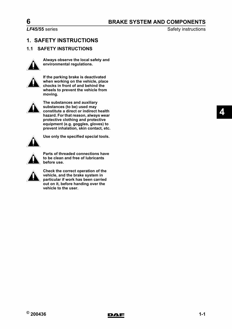
© 200436 1-1
Safety instructionsBRAKE SYSTEM AND COMPONENTS
ΛΦ45/55 series6
4
1. SAFETY INSTRUCTIONS1.1 SAFETY INSTRUCTIONS
Always observe the local safety and environmental regulations.
If the parking brake is deactivated when working on the vehicle, place chocks in front of and behind the wheels to prevent the vehicle from moving.
The substances and auxiliary substances (to be) used may constitute a direct or indirect health hazard. For that reason, always wear protective clothing and protective equipment (e.g. goggles, gloves) to prevent inhalation, skin contact, etc.
Use only the specified special tools.
Parts of threaded connections have to be clean and free of lubricants before use.
Check the correct operation of the vehicle, and the brake system in particular if work has been carried out on it, before handing over the vehicle to the user.
}}}}}}
https://www.truck-manuals.net/
BRAKE SYSTEM AND COMPONENTS
1-2 © 200436
Safety instructions
4
ΛΦ45/55 series6
https://www.truck-manuals.net/
© 200436 2-1
Inspection and adjustmentBRAKE SYSTEM AND COMPONENTS
ΛΦ45/55 series6
4
2. INSPECTION AND ADJUSTMENT2.1 INSPECTION, COMPRESSOR CAPACITY
1. Bring the engine up to operating temperature.
2. For a vehicle with air suspension, the chassis should be at the normal driving height.
3. Put chocks in front of and behind the rear-axle wheels to prevent the vehicle from moving.
4. Position the parking brake in the driving position.
Note:If, when draining the air reservoirs, they appear to hold an excessive quantity of oil, check the condition of the compressor and check the compressor for the presence of carbon deposits in the compressor pipes.
5. Bleed the entire brake system.
6. The capacity test requires that a completely empty system should be at operating pressure within 5 minutes, at an engine speed of 0.6 x maximum engine speed.
https://www.truck-manuals.net/
BRAKE SYSTEM AND COMPONENTS
2-2 © 200436
Inspection and adjustment
4
ΛΦ45/55 series6
2.2 INSPECTION, FOOT BRAKE VALVE
Inspection, foot brake valve1. Connect a pressure gauge to a brake
chamber of the front axle (in front of the empty/load valve, if present).
2. Connect a pressure gauge to the test connection of the load-dependent control valve.
3. Pressurise the system.
4. Depress the brake pedal a few times, alternately quickly and slowly, until the end stop is reached. Check if there is a discrepancy between both gauge readings (discrepancy maximum 0.3 ≥ 0.15 bar, at circuit 21 between 0 and 3 bar).
5. If the brake pedal is gradually depressed, there must be no pressure jumps of more than 0.3 ≥ 0.15 bar in either circuit, at circuit 21 between 0 and 3 bar.
6. When the foot brake valve is completely depressed, the reading of both gauges should indicate the max. output pressure.See "Technical data".
7. When the brake pedal is not depressed, the pressure gauges should not indicate any pressure.
https://www.truck-manuals.net/
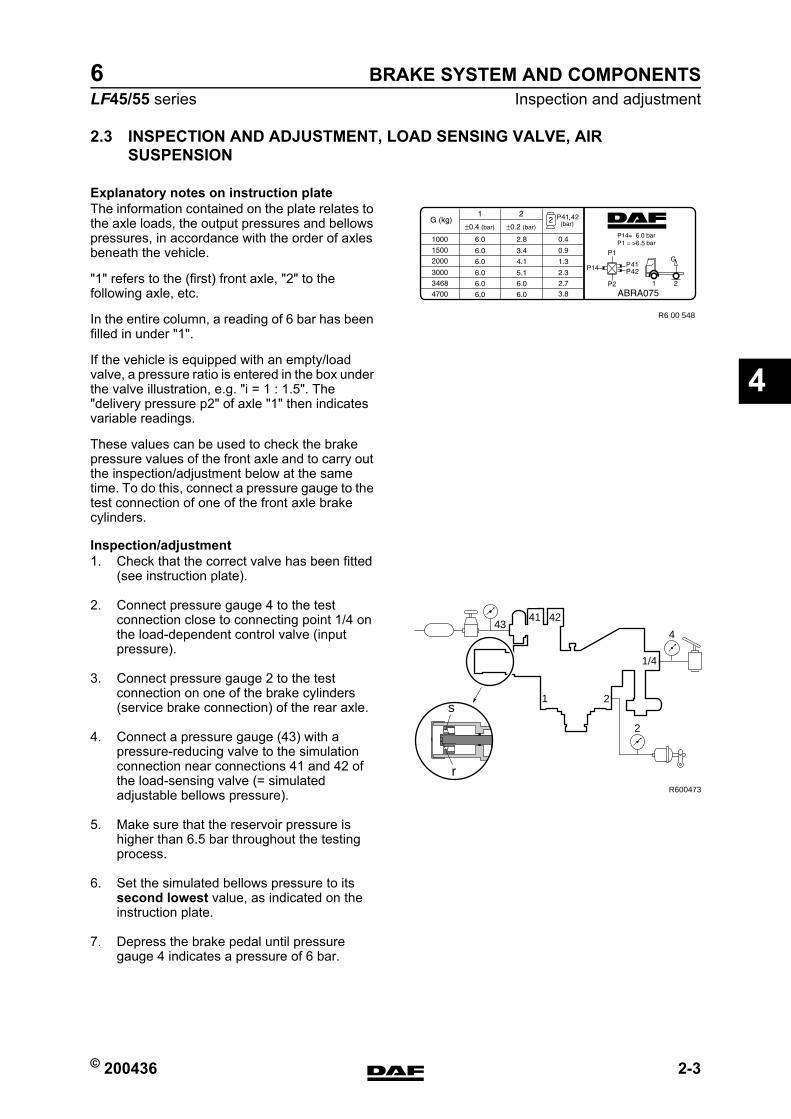
© 200436 2-3
Inspection and adjustmentBRAKE SYSTEM AND COMPONENTS
ΛΦ45/55 series6
4
2.3 INSPECTION AND ADJUSTMENT, LOAD SENSING VALVE, AIR SUSPENSION
Explanatory notes on instruction plateThe information contained on the plate relates to the axle loads, the output pressures and bellows pressures, in accordance with the order of axles beneath the vehicle.
"1" refers to the (first) front axle, "2" to the following axle, etc.
In the entire column, a reading of 6 bar has been filled in under "1".
If the vehicle is equipped with an empty/load valve, a pressure ratio is entered in the box under the valve illustration, e.g. "i = 1 : 1.5". The "delivery pressure p2" of axle "1" then indicates variable readings.
These values can be used to check the brake pressure values of the front axle and to carry out the inspection/adjustment below at the same time. To do this, connect a pressure gauge to the test connection of one of the front axle brake cylinders.
Inspection/adjustment1. Check that the correct valve has been fitted
(see instruction plate).
2. Connect pressure gauge 4 to the test connection close to connecting point 1/4 on the load-dependent control valve (input pressure).
3. Connect pressure gauge 2 to the test connection on one of the brake cylinders (service brake connection) of the rear axle.
4. Connect a pressure gauge (43) with a pressure-reducing valve to the simulation connection near connections 41 and 42 of the load-sensing valve (= simulated adjustable bellows pressure).
5. Make sure that the reservoir pressure is higher than 6.5 bar throughout the testing process.
6. Set the simulated bellows pressure to its second lowest value, as indicated on the instruction plate.
7. Depress the brake pedal until pressure gauge 4 indicates a pressure of 6 bar.
R6 00 548
43
1/4
4
2
2
R600473
1
41 42
r
s
https://www.truck-manuals.net/
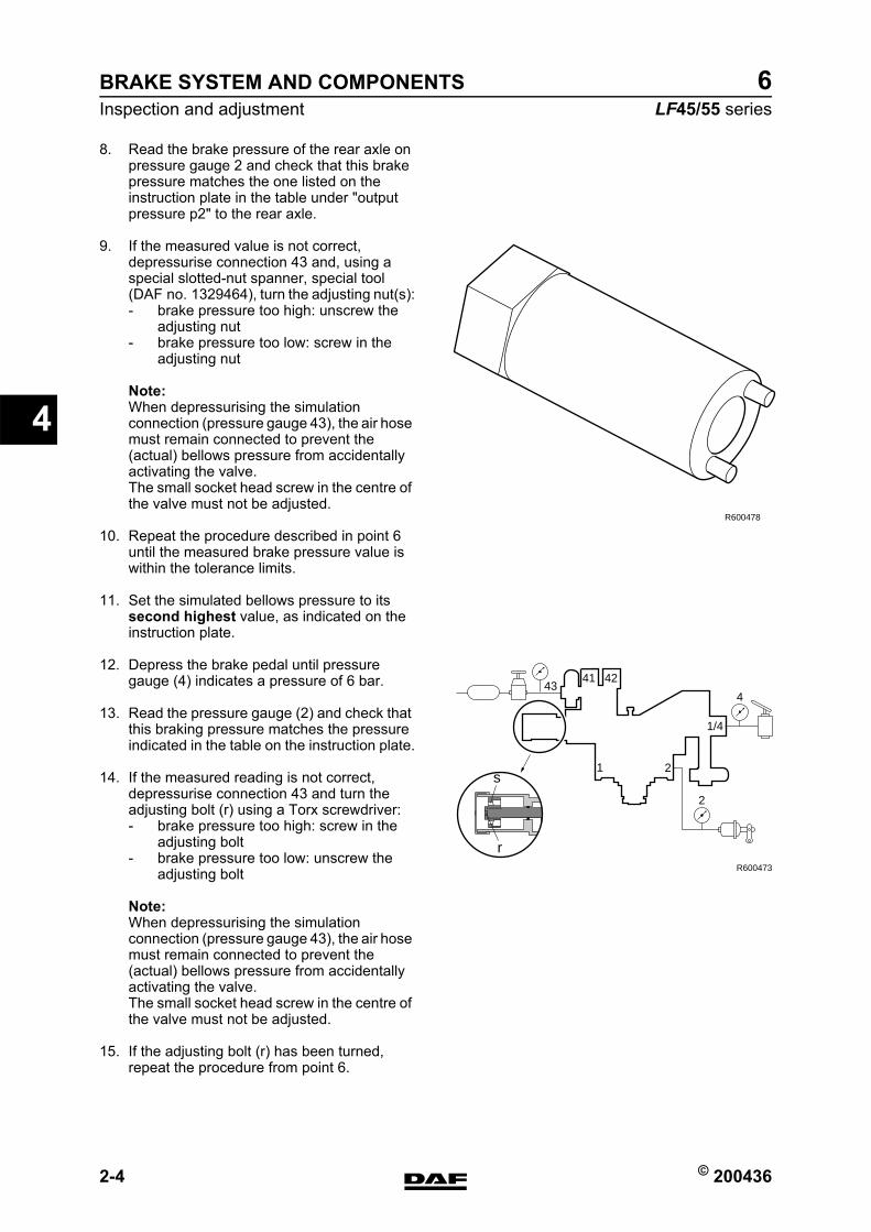
BRAKE SYSTEM AND COMPONENTS
2-4 © 200436
Inspection and adjustment
4
ΛΦ45/55 series6
8. Read the brake pressure of the rear axle on pressure gauge 2 and check that this brake pressure matches the one listed on the instruction plate in the table under "output pressure p2" to the rear axle.
9. If the measured value is not correct, depressurise connection 43 and, using a special slotted-nut spanner, special tool (DAF no. 1329464), turn the adjusting nut(s):- brake pressure too high: unscrew the
adjusting nut- brake pressure too low: screw in the
adjusting nut
Note:When depressurising the simulation connection (pressure gauge 43), the air hose must remain connected to prevent the (actual) bellows pressure from accidentally activating the valve.The small socket head screw in the centre of the valve must not be adjusted.
10. Repeat the procedure described in point 6 until the measured brake pressure value is within the tolerance limits.
11. Set the simulated bellows pressure to its second highest value, as indicated on the instruction plate.
12. Depress the brake pedal until pressure gauge (4) indicates a pressure of 6 bar.
13. Read the pressure gauge (2) and check that this braking pressure matches the pressure indicated in the table on the instruction plate.
14. If the measured reading is not correct, depressurise connection 43 and turn the adjusting bolt (r) using a Torx screwdriver:- brake pressure too high: screw in the
adjusting bolt- brake pressure too low: unscrew the
adjusting bolt
Note:When depressurising the simulation connection (pressure gauge 43), the air hose must remain connected to prevent the (actual) bellows pressure from accidentally activating the valve.The small socket head screw in the centre of the valve must not be adjusted.
15. If the adjusting bolt (r) has been turned, repeat the procedure from point 6.
R600478
43
1/4
4
2
2
R600473
1
41 42
r
s
https://www.truck-manuals.net/
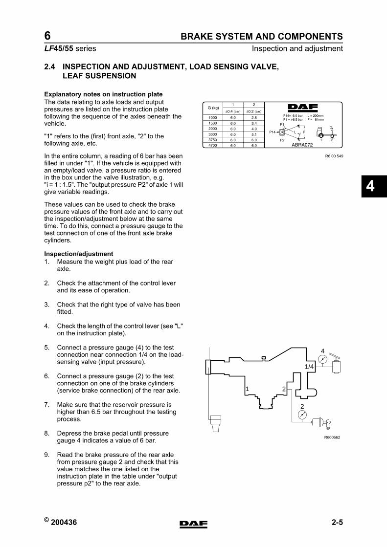
© 200436 2-5
Inspection and adjustmentBRAKE SYSTEM AND COMPONENTS
ΛΦ45/55 series6
4
2.4 INSPECTION AND ADJUSTMENT, LOAD SENSING VALVE, LEAF SUSPENSION
Explanatory notes on instruction plateThe data relating to axle loads and output pressures are listed on the instruction plate following the sequence of the axles beneath the vehicle.
"1" refers to the (first) front axle, "2" to the following axle, etc.
In the entire column, a reading of 6 bar has been filled in under "1". If the vehicle is equipped with an empty/load valve, a pressure ratio is entered in the box under the valve illustration, e.g. "i = 1 : 1.5". The "output pressure P2" of axle 1 will give variable readings.
These values can be used to check the brake pressure values of the front axle and to carry out the inspection/adjustment below at the same time. To do this, connect a pressure gauge to the test connection of one of the front axle brake cylinders.
Inspection/adjustment1. Measure the weight plus load of the rear
axle.
2. Check the attachment of the control lever and its ease of operation.
3. Check that the right type of valve has been fitted.
4. Check the length of the control lever (see "L" on the instruction plate).
5. Connect a pressure gauge (4) to the test connection near connection 1/4 on the load-sensing valve (input pressure).
6. Connect a pressure gauge (2) to the test connection on one of the brake cylinders (service brake connection) of the rear axle.
7. Make sure that the reservoir pressure is higher than 6.5 bar throughout the testing process.
8. Depress the brake pedal until pressure gauge 4 indicates a value of 6 bar.
9. Read the brake pressure of the rear axle from pressure gauge 2 and check that this value matches the one listed on the instruction plate in the table under "output pressure p2" to the rear axle.
R6 00 549
1/4
4
2
2
R600562
1
https://www.truck-manuals.net/
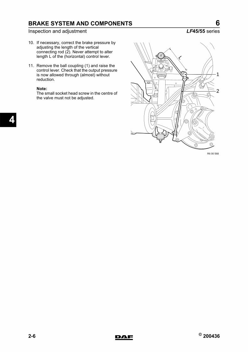
BRAKE SYSTEM AND COMPONENTS
2-6 © 200436
Inspection and adjustment
4
ΛΦ45/55 series6
10. If necessary, correct the brake pressure by adjusting the length of the vertical connecting rod (2). Never attempt to alter length L of the (horizontal) control lever.
11. Remove the ball coupling (1) and raise the control lever. Check that the output pressure is now allowed through (almost) without reduction.
Note:The small socket head screw in the centre of the valve must not be adjusted.
1
2
R6 00 568
L
https://www.truck-manuals.net/
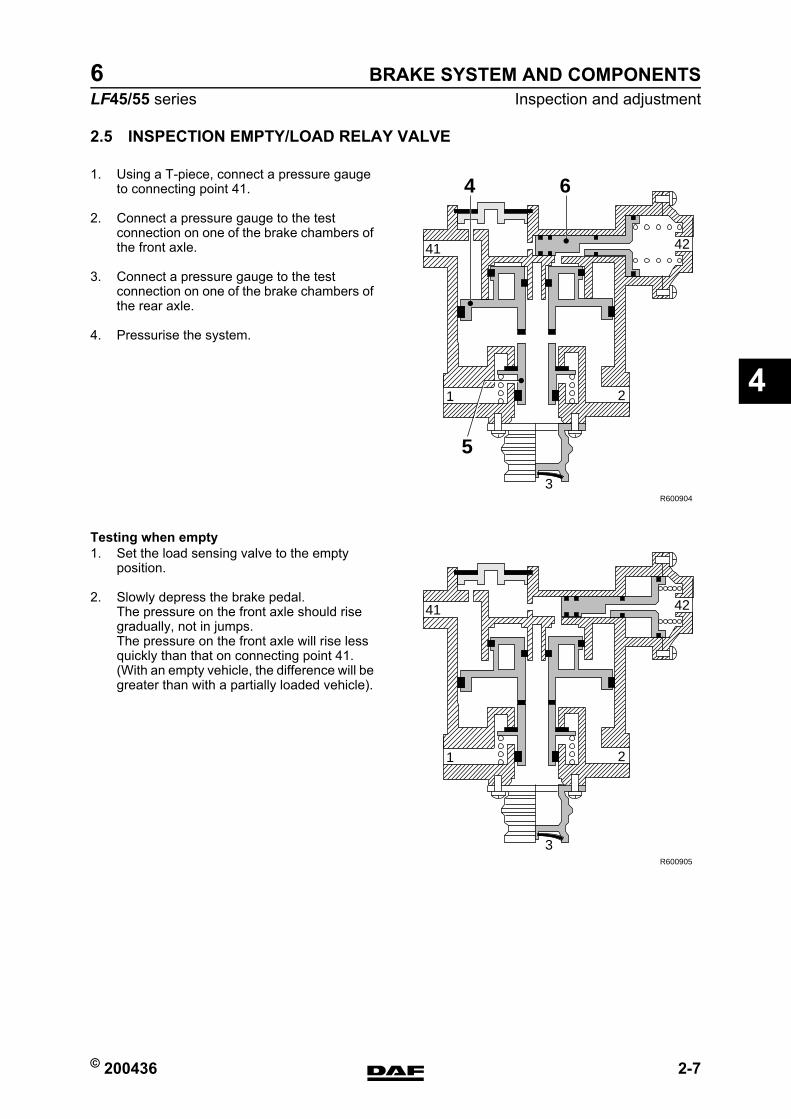
© 200436 2-7
Inspection and adjustmentBRAKE SYSTEM AND COMPONENTS
ΛΦ45/55 series6
4
2.5 INSPECTION EMPTY/LOAD RELAY VALVE
1. Using a T-piece, connect a pressure gauge to connecting point 41.
2. Connect a pressure gauge to the test connection on one of the brake chambers of the front axle.
3. Connect a pressure gauge to the test connection on one of the brake chambers of the rear axle.
4. Pressurise the system.
Testing when empty1. Set the load sensing valve to the empty
position.
2. Slowly depress the brake pedal.The pressure on the front axle should rise gradually, not in jumps.The pressure on the front axle will rise less quickly than that on connecting point 41. (With an empty vehicle, the difference will be greater than with a partially loaded vehicle).
1 2
3
4241
R600904
4 6
5
1 2
3
4241
R600905
https://www.truck-manuals.net/
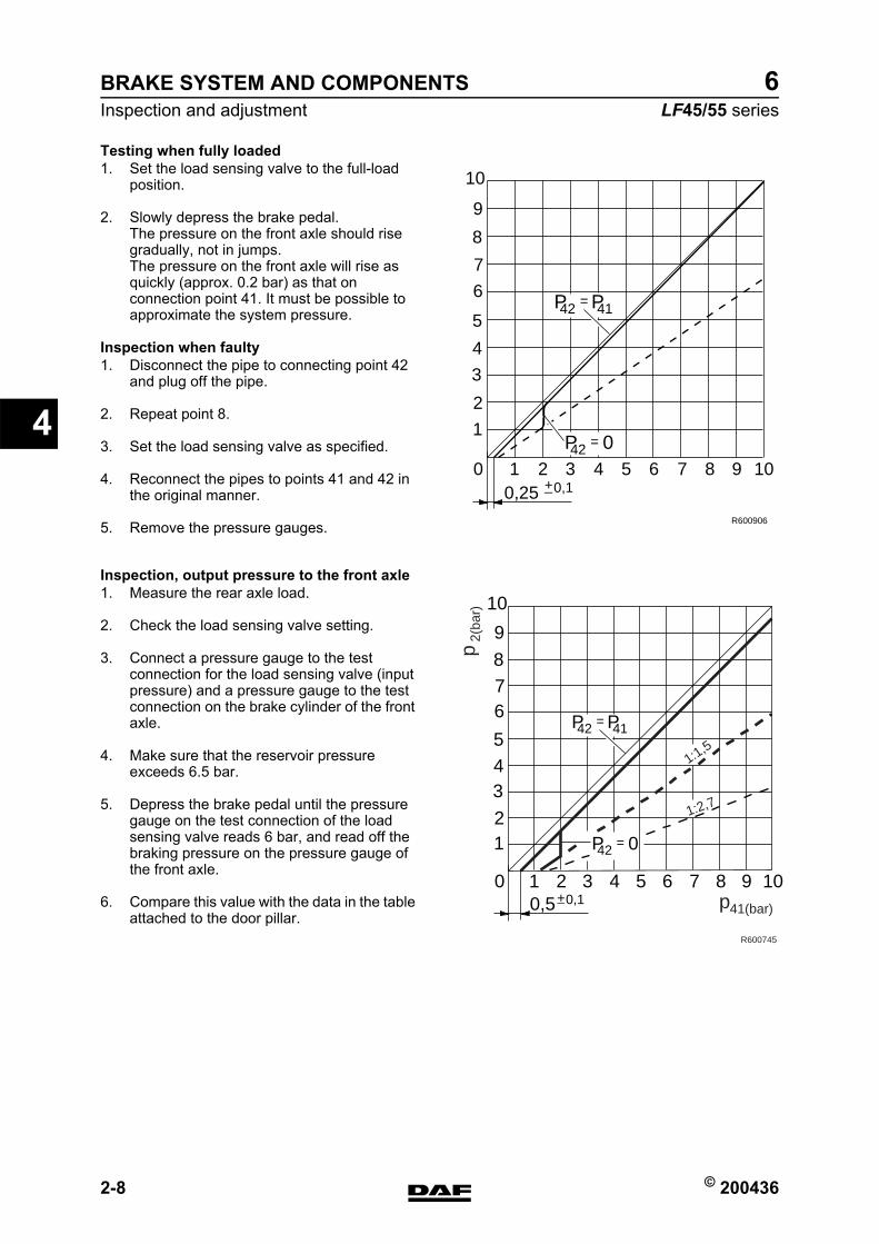
BRAKE SYSTEM AND COMPONENTS
2-8 © 200436
Inspection and adjustment
4
ΛΦ45/55 series6
Testing when fully loaded1. Set the load sensing valve to the full-load
position.
2. Slowly depress the brake pedal.The pressure on the front axle should rise gradually, not in jumps.The pressure on the front axle will rise as quickly (approx. 0.2 bar) as that on connection point 41. It must be possible to approximate the system pressure.
Inspection when faulty1. Disconnect the pipe to connecting point 42
and plug off the pipe.
2. Repeat point 8.
3. Set the load sensing valve as specified.
4. Reconnect the pipes to points 41 and 42 in the original manner.
5. Remove the pressure gauges.
Inspection, output pressure to the front axle1. Measure the rear axle load.
2. Check the load sensing valve setting.
3. Connect a pressure gauge to the test connection for the load sensing valve (input pressure) and a pressure gauge to the test connection on the brake cylinder of the front axle.
4. Make sure that the reservoir pressure exceeds 6.5 bar.
5. Depress the brake pedal until the pressure gauge on the test connection of the load sensing valve reads 6 bar, and read off the braking pressure on the pressure gauge of the front axle.
6. Compare this value with the data in the table attached to the door pillar.
00,10,25
1
1
2
2
3
3
4
4
5
5
6
6
7
7
8
8
9
9
10
10
+_
R600906
P 042 =
P42 P41=
00,10,5
1
1
2
2
3
3
4
4
5
5
6
6
7
7
8
8
9
9
10
10
P 042 =
P42 P41=
1:2,7
1:1,5
41(bar)p
2(ba
r)p
R600745
https://www.truck-manuals.net/
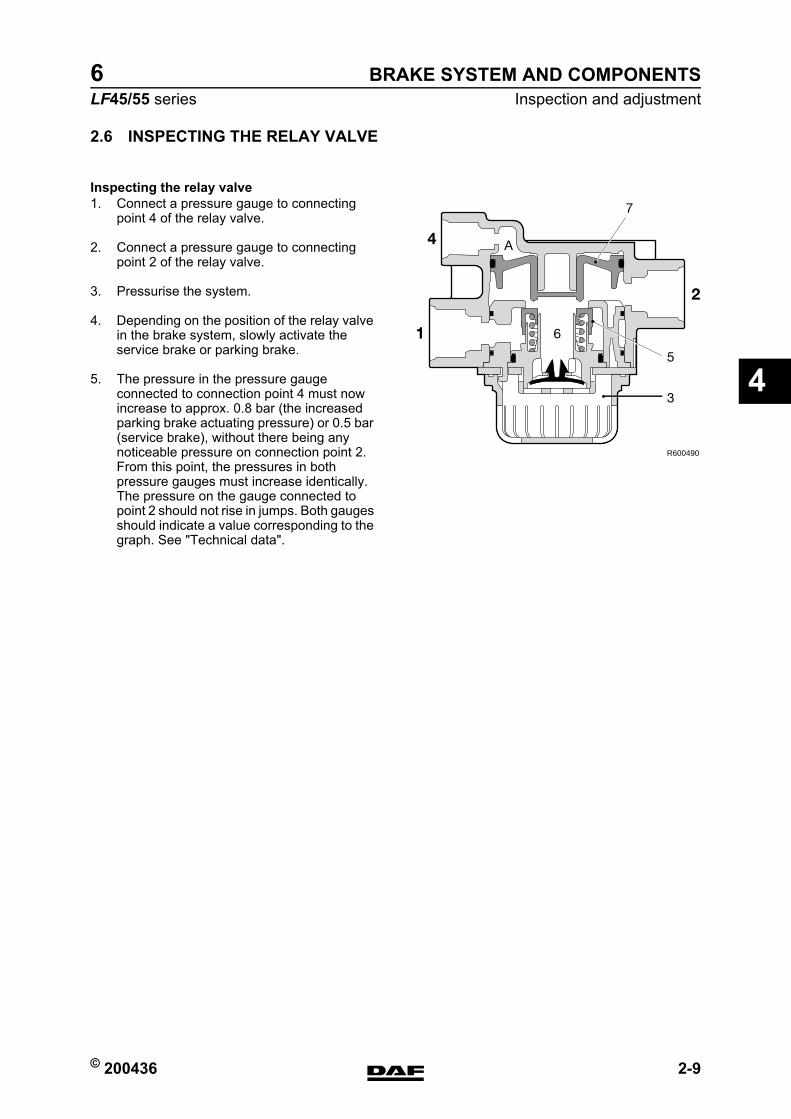
© 200436 2-9
Inspection and adjustmentBRAKE SYSTEM AND COMPONENTS
ΛΦ45/55 series6
4
2.6 INSPECTING THE RELAY VALVE
Inspecting the relay valve1. Connect a pressure gauge to connecting
point 4 of the relay valve.
2. Connect a pressure gauge to connecting point 2 of the relay valve.
3. Pressurise the system.
4. Depending on the position of the relay valve in the brake system, slowly activate the service brake or parking brake.
5. The pressure in the pressure gauge connected to connection point 4 must now increase to approx. 0.8 bar (the increased parking brake actuating pressure) or 0.5 bar (service brake), without there being any noticeable pressure on connection point 2. From this point, the pressures in both pressure gauges must increase identically. The pressure on the gauge connected to point 2 should not rise in jumps. Both gauges should indicate a value corresponding to the graph. See "Technical data".
R600490
2
1 6
4 A
5
3
7
https://www.truck-manuals.net/
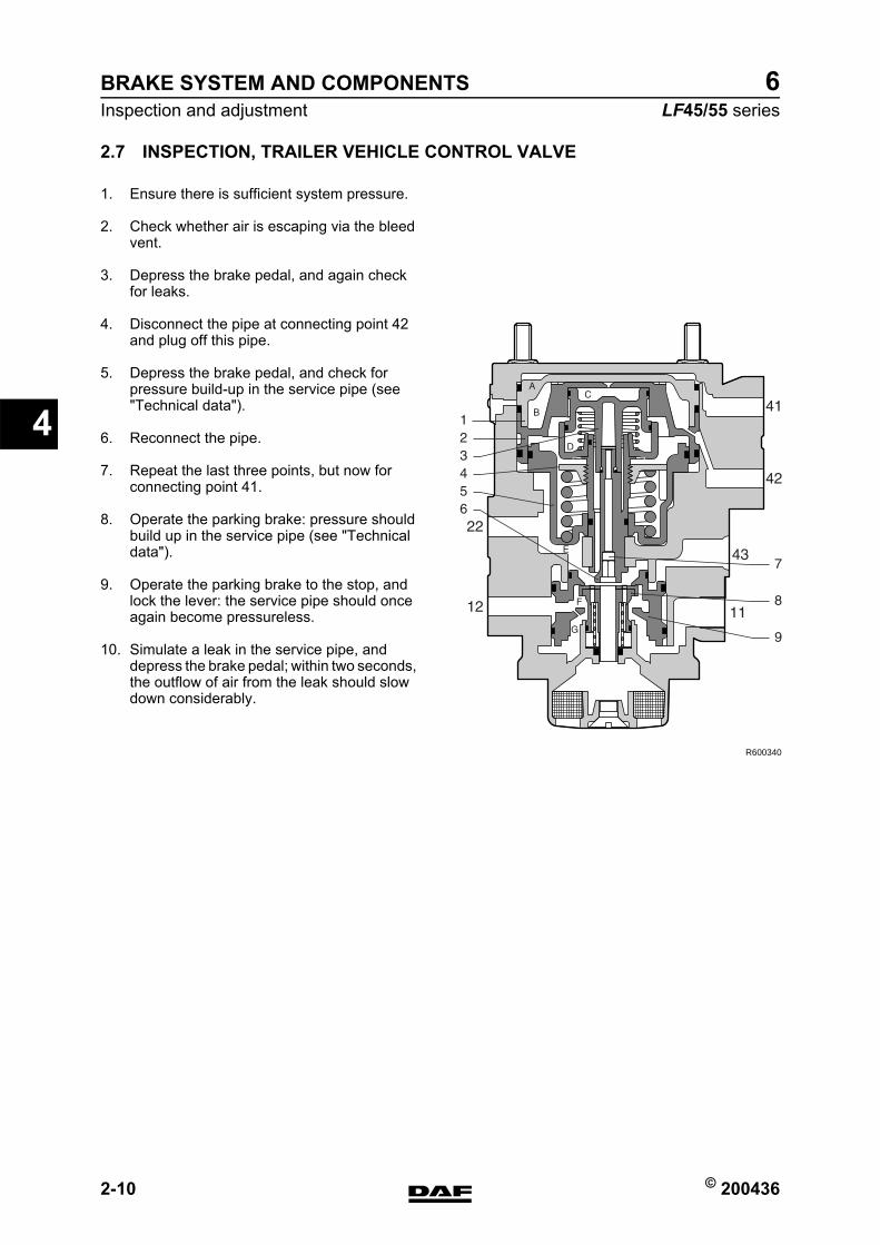
BRAKE SYSTEM AND COMPONENTS
2-10 © 200436
Inspection and adjustment
4
ΛΦ45/55 series6
2.7 INSPECTION, TRAILER VEHICLE CONTROL VALVE
1. Ensure there is sufficient system pressure.
2. Check whether air is escaping via the bleed vent.
3. Depress the brake pedal, and again check for leaks.
4. Disconnect the pipe at connecting point 42 and plug off this pipe.
5. Depress the brake pedal, and check for pressure build-up in the service pipe (see "Technical data").
6. Reconnect the pipe.
7. Repeat the last three points, but now for connecting point 41.
8. Operate the parking brake: pressure should build up in the service pipe (see "Technical data").
9. Operate the parking brake to the stop, and lock the lever: the service pipe should once again become pressureless.
10. Simulate a leak in the service pipe, and depress the brake pedal; within two seconds, the outflow of air from the leak should slow down considerably.
R600340
https://www.truck-manuals.net/
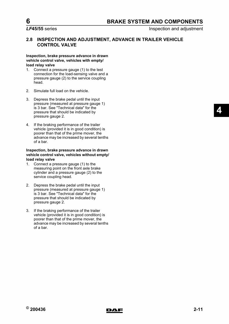
© 200436 2-11
Inspection and adjustmentBRAKE SYSTEM AND COMPONENTS
ΛΦ45/55 series6
4
2.8 INSPECTION AND ADJUSTMENT, ADVANCE IN TRAILER VEHICLE CONTROL VALVE
Inspection, brake pressure advance in drawn vehicle control valve, vehicles with empty/load relay valve1. Connect a pressure gauge (1) to the test
connection for the load-sensing valve and a pressure gauge (2) to the service coupling head.
2. Simulate full load on the vehicle.
3. Depress the brake pedal until the input pressure (measured at pressure gauge 1) is 3 bar. See "Technical data" for the pressure that should be indicated by pressure gauge 2.
4. If the braking performance of the trailer vehicle (provided it is in good condition) is poorer than that of the prime mover, the advance may be increased by several tenths of a bar.
Inspection, brake pressure advance in drawn vehicle control valve, vehicles without empty/load relay valve1. Connect a pressure gauge (1) to the
measuring point on the front axle brake cylinder and a pressure gauge (2) to the service coupling head.
2. Depress the brake pedal until the input pressure (measured at pressure gauge 1) is 3 bar. See "Technical data" for the pressure that should be indicated by pressure gauge 2.
3. If the braking performance of the trailer vehicle (provided it is in good condition) is poorer than that of the prime mover, the advance may be increased by several tenths of a bar.
https://www.truck-manuals.net/
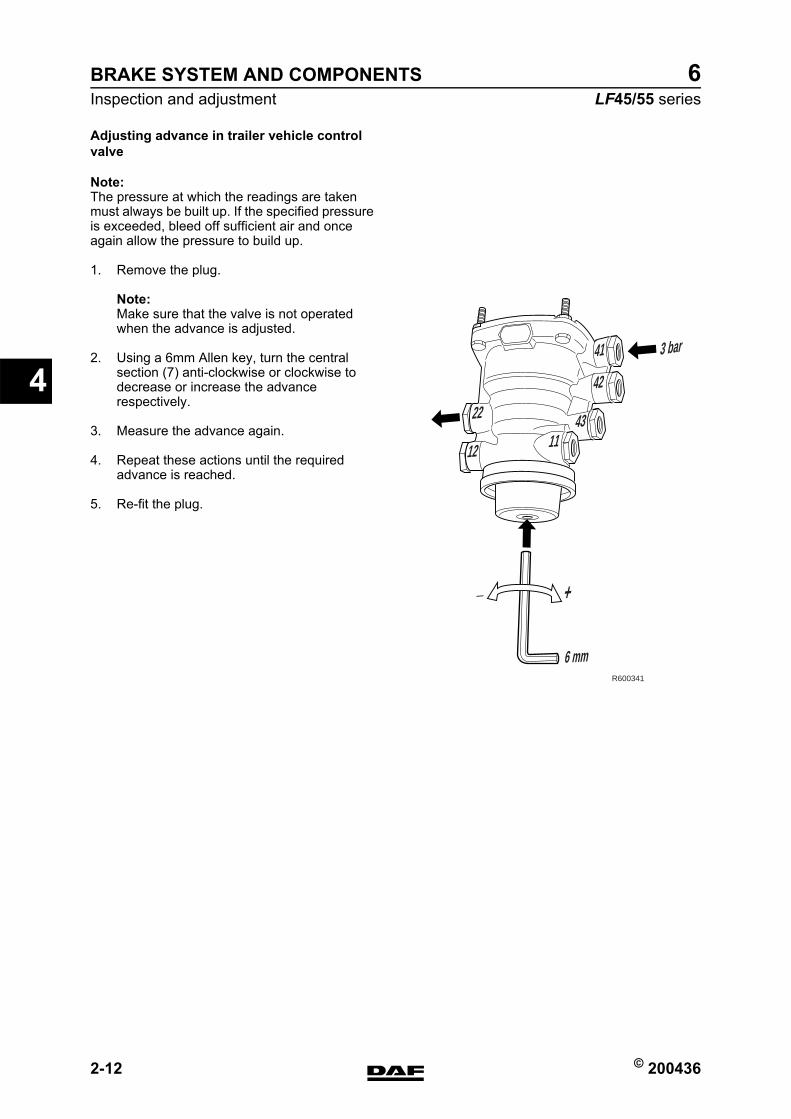
BRAKE SYSTEM AND COMPONENTS
2-12 © 200436
Inspection and adjustment
4
ΛΦ45/55 series6
Adjusting advance in trailer vehicle control valve
Note:The pressure at which the readings are taken must always be built up. If the specified pressure is exceeded, bleed off sufficient air and once again allow the pressure to build up.
1. Remove the plug.
Note:Make sure that the valve is not operated when the advance is adjusted.
2. Using a 6mm Allen key, turn the central section (7) anti-clockwise or clockwise to decrease or increase the advance respectively.
3. Measure the advance again.
4. Repeat these actions until the required advance is reached.
5. Re-fit the plug.
41
42
3 bar
6 mm
4311
12
+_
22
R600341
https://www.truck-manuals.net/
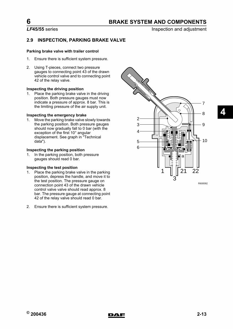
© 200436 2-13
Inspection and adjustmentBRAKE SYSTEM AND COMPONENTS
ΛΦ45/55 series6
4
2.9 INSPECTION, PARKING BRAKE VALVE
Parking brake valve with trailer control
1. Ensure there is sufficient system pressure.
2. Using T-pieces, connect two pressure gauges to connecting point 43 of the drawn vehicle control valve and to connecting point 42 of the relay valve.
Inspecting the driving position1. Place the parking brake valve in the driving
position. Both pressure gauges must now indicate a pressure of approx. 8 bar. This is the limiting pressure of the air supply unit.
Inspecting the emergency brake1. Move the parking brake valve slowly towards
the parking position. Both pressure gauges should now gradually fall to 0 bar (with the exception of the first 10 angular displacement. See graph in "Technical data").
Inspecting the parking position1. In the parking position, both pressure
gauges should read 0 bar.
Inspecting the test position1. Place the parking brake valve in the parking
position, depress the handle, and move it to the test position. The pressure gauge on connection point 43 of the drawn vehicle control valve valve should read approx. 8 bar. The pressure gauge at connecting point 42 of the relay valve should read 0 bar.
2. Ensure there is sufficient system pressure.
3211 22
a
23
5
4
6
8
7
9
10
R600092
https://www.truck-manuals.net/
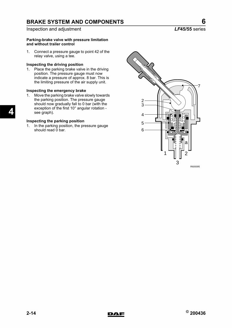
BRAKE SYSTEM AND COMPONENTS
2-14 © 200436
Inspection and adjustment
4
ΛΦ45/55 series6
Parking-brake valve with pressure limitation and without trailer control
1. Connect a pressure gauge to point 42 of the relay valve, using a tee.
Inspecting the driving position1. Place the parking brake valve in the driving
position. The pressure gauge must now indicate a pressure of approx. 8 bar. This is the limiting pressure of the air supply unit.
Inspecting the emergency brake1. Move the parking brake valve slowly towards
the parking position. The pressure gauge should now gradually fall to 0 bar (with the exception of the first 10 angular rotation - see graph).
Inspecting the parking position1. In the parking position, the pressure gauge
should read 0 bar.
R600095
2
7
3
4
5
6
1
3
2
a
https://www.truck-manuals.net/
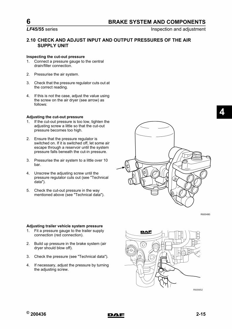
© 200436 2-15
Inspection and adjustmentBRAKE SYSTEM AND COMPONENTS
ΛΦ45/55 series6
4
2.10 CHECK AND ADJUST INPUT AND OUTPUT PRESSURES OF THE AIR SUPPLY UNIT
Inspecting the cut-out pressure1. Connect a pressure gauge to the central
drain/filler connection.
2. Pressurise the air system.
3. Check that the pressure regulator cuts out at the correct reading.
4. If this is not the case, adjust the value using the screw on the air dryer (see arrow) as follows:
Adjusting the cut-out pressure1. If the cut-out pressure is too low, tighten the
adjusting screw a little so that the cut-out pressure becomes too high.
2. Ensure that the pressure regulator is switched on. If it is switched off, let some air escape through a reservoir until the system pressure falls beneath the cut-in pressure.
3. Pressurise the air system to a little over 10 bar.
4. Unscrew the adjusting screw until the pressure regulator cuts out (see "Technical data").
5. Check the cut-out pressure in the way mentioned above (see "Technical data").
Adjusting trailer vehicle system pressure1. Fit a pressure gauge to the trailer supply
connection (red connection).
2. Build up pressure in the brake system (air dryer should blow off).
3. Check the pressure (see "Technical data").
4. If necessary, adjust the pressure by turning the adjusting screw.
R600480
R600652
https://www.truck-manuals.net/
BRAKE SYSTEM AND COMPONENTS
2-16 © 200436
Inspection and adjustment
4
ΛΦ45/55 series6
2.11 CHECK AIR DRYER REGENERATION FUNCTION IN THE AIR SUPPLY UNIT
Air dryer regeneration function1. Pressurise the air system (pressure
regulator should cut out).
2. Switch the engine off.
3. The regeneration air should escape via the vent opening of the air dryer, for approximately 20 seconds.
https://www.truck-manuals.net/
© 200436 2-17
Inspection and adjustmentBRAKE SYSTEM AND COMPONENTS
ΛΦ45/55 series6
4
2.12 CHECK THE 4-CIRCUIT SECURITY VALVE OF THE AIR SUPPLY UNIT
Check pressure build-up on circuits 1, 2, 3 and 41. Lower the pressure in the system to 0 bar.2. Connect pressure gauges to circuits 1, 2, 3
and 4.3. Pressurise the circuits using the compressor
(engine speed approx. 1000 rpm).4. The pressure in circuits 1, 2 and 4 will
gradually increase. Once the opening pressure of circuit 3 has been reached (see "Technical Data"), the pressure in circuit 3 will increase.
5. If no more pressure builds up (cut-out pressure reached), the supply pressure in circuits 1, 2, 3 and 4 must meet the stipulated value (see "Technical Data".
Checking circuit 11. Turn off the engine and simulate a leak in
circuit 1.2. The pressure in circuit 2 and 4 may not fall
below the specified closing pressure of circuit 1. See "Technical data".
Checking circuit 21. Make sure the leak in circuit 1 is remedied
and pressurise the system again.2. Turn off the engine and simulate a leak in
circuit 2.3. The pressure in circuit 1 and 4 may not fall
below the specified closing pressure of circuit 2. See "Technical data".
Checking circuit 31. Make sure the leak in circuit 2 is remedied
and pressurise the system again.2. Turn off the engine and simulate a leak in
circuit 3 for the trailer circuit (connection point 23).
3. The pressure in circuit 1.2 and 4 may not fall below the specified closing pressure of circuit 3. See "Technical data".
4. The pressure in circuit 3 for the parking brake circuit (connection point 25) must remain secured by the check valve.
Checking circuit 41. Make sure the leak in circuit 3 is remedied
and pressurise the system again.2. Turn off the engine and simulate a leak in
circuit 4.3. The pressure in circuit 1 and 2 may not fall
below the specified closing pressure of circuit 4. See "Technical data".
https://www.truck-manuals.net/
BRAKE SYSTEM AND COMPONENTS
2-18 © 200436
Inspection and adjustment
4
ΛΦ45/55 series6
Checking circuit 3 flow-back function1. Make sure the leak in circuit 4 is remedied
and pressurise the system again.2. Turn off the engine and simulate a leak in
circuit 1.3. The pressure in circuit 3 for the trailer circuit
(connection point 23) will decrease to 0 bar when the pressure in circuit 1 has reached the activation pressure for the flow-back function. See "Technical data".
https://www.truck-manuals.net/
© 200436 2-19
Inspection and adjustmentBRAKE SYSTEM AND COMPONENTS
ΛΦ45/55 series6
4
2.13 INSPECTING BRAKE PADS, WABCO MODEL
With wheels fitted
No external wear indicators are fitted on these models. The brake pad thickness must be inspected by using a mirror and a lamp, if necessary.
https://www.truck-manuals.net/
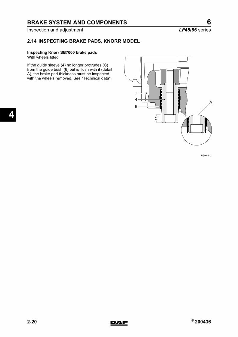
BRAKE SYSTEM AND COMPONENTS
2-20 © 200436
Inspection and adjustment
4
ΛΦ45/55 series6
2.14 INSPECTING BRAKE PADS, KNORR MODEL
Inspecting Knorr SB7000 brake padsWith wheels fitted:
If the guide sleeve (4) no longer protrudes (C) from the guide bush (6) but is flush with it (detail A), the brake pad thickness must be inspected with the wheels removed. See "Technical data".
C
1
4
6
R600481
A
https://www.truck-manuals.net/
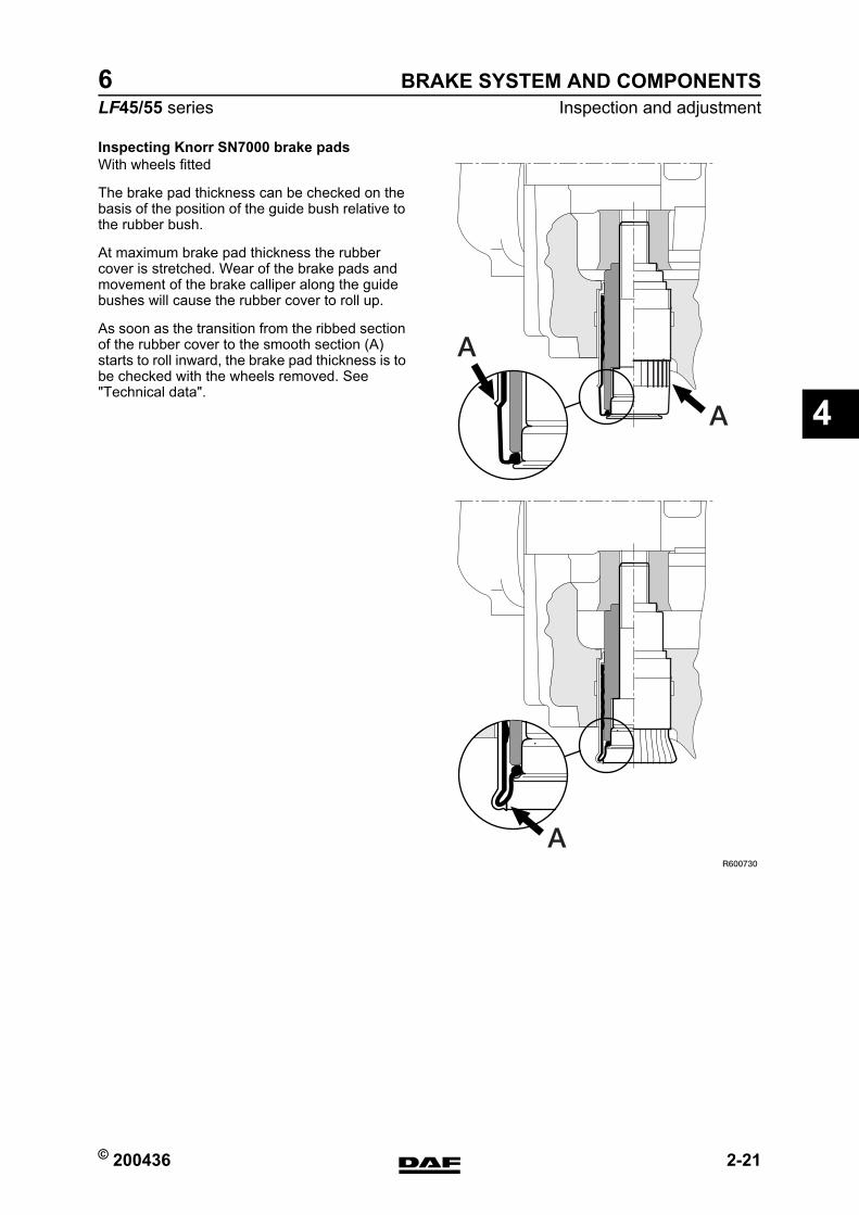
© 200436 2-21
Inspection and adjustmentBRAKE SYSTEM AND COMPONENTS
ΛΦ45/55 series6
4
Inspecting Knorr SN7000 brake padsWith wheels fitted
The brake pad thickness can be checked on the basis of the position of the guide bush relative to the rubber bush.
At maximum brake pad thickness the rubber cover is stretched. Wear of the brake pads and movement of the brake calliper along the guide bushes will cause the rubber cover to roll up.
As soon as the transition from the ribbed section of the rubber cover to the smooth section (A) starts to roll inward, the brake pad thickness is to be checked with the wheels removed. See "Technical data".
A
A
AR600730
https://www.truck-manuals.net/
BRAKE SYSTEM AND COMPONENTS
2-22 © 200436
Inspection and adjustment
4
ΛΦ45/55 series6
2.15 INSPECTION, BRAKE DISCS
1. Remove the wheels.
2. Measure the disc thickness at different points to find the thinnest measurement. Compare the reading with the technical data. See "Technical data".
3. Check the brake discs for signs of wear. See "Technical data".
Note:The brake discs may be turned. See "Technical data".
https://www.truck-manuals.net/
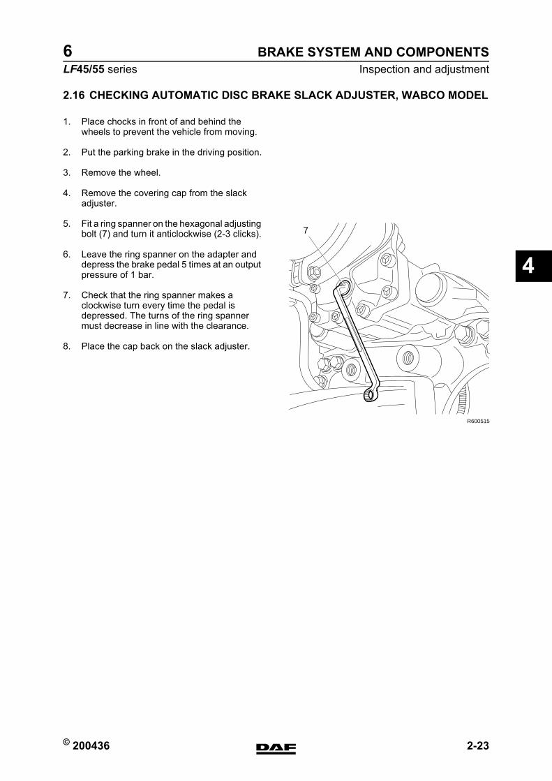
© 200436 2-23
Inspection and adjustmentBRAKE SYSTEM AND COMPONENTS
ΛΦ45/55 series6
4
2.16 CHECKING AUTOMATIC DISC BRAKE SLACK ADJUSTER, WABCO MODEL
1. Place chocks in front of and behind the wheels to prevent the vehicle from moving.
2. Put the parking brake in the driving position.
3. Remove the wheel.
4. Remove the covering cap from the slack adjuster.
5. Fit a ring spanner on the hexagonal adjusting bolt (7) and turn it anticlockwise (2-3 clicks).
6. Leave the ring spanner on the adapter and depress the brake pedal 5 times at an output pressure of 1 bar.
7. Check that the ring spanner makes a clockwise turn every time the pedal is depressed. The turns of the ring spanner must decrease in line with the clearance.
8. Place the cap back on the slack adjuster.
R600515
7
https://www.truck-manuals.net/
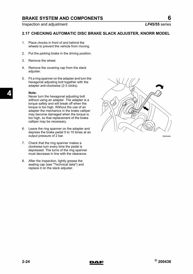
BRAKE SYSTEM AND COMPONENTS
2-24 © 200436
Inspection and adjustment
4
ΛΦ45/55 series6
2.17 CHECKING AUTOMATIC DISC BRAKE SLACK ADJUSTER, KNORR MODEL
1. Place chocks in front of and behind the wheels to prevent the vehicle from moving.
2. Put the parking brake in the driving position.
3. Remove the wheel.
4. Remove the covering cap from the slack adjuster.
5. Fit a ring spanner on the adapter and turn the hexagonal adjusting bolt together with the adapter anti-clockwise (2-3 clicks).
Note:Never turn the hexagonal adjusting bolt without using an adapter. The adapter is a torque safety and will break off when the torque is too high. Without the use of an adapter the mechanics in the brake calliper may become damaged when the torque is too high, so that replacement of the brake calliper may be necessary.
6. Leave the ring spanner on the adapter and depress the brake pedal 5 to 10 times at an output pressure of 2 bar.
7. Check that the ring spanner makes a clockwise turn every time the pedal is depressed. The turns of the ring spanner must decrease in line with the clearance.
8. After the inspection, lightly grease the sealing cap (see "Technical data") and replace it on the slack adjuster.
R600468
https://www.truck-manuals.net/
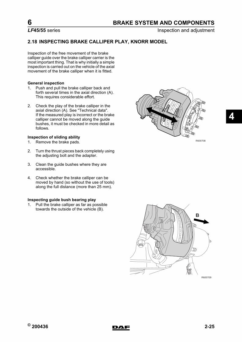
© 200436 2-25
Inspection and adjustmentBRAKE SYSTEM AND COMPONENTS
ΛΦ45/55 series6
4
2.18 INSPECTING BRAKE CALLIPER PLAY, KNORR MODEL
Inspection of the free movement of the brake calliper guide over the brake calliper carrier is the most important thing. That is why initially a simple inspection is carried out on the vehicle of the axial movement of the brake calliper when it is fitted.
General inspection1. Push and pull the brake calliper back and
forth several times in the axial direction (A). This requires considerable effort.
2. Check the play of the brake calliper in the axial direction (A). See "Technical data".If the measured play is incorrect or the brake calliper cannot be moved along the guide bushes, it must be checked in more detail as follows.
Inspection of sliding ability1. Remove the brake pads.
2. Turn the thrust pieces back completely using the adjusting bolt and the adapter.
3. Clean the guide bushes where they are accessible.
4. Check whether the brake calliper can be moved by hand (so without the use of tools) along the full distance (more than 25 mm).
Inspecting guide bush bearing play1. Pull the brake calliper as far as possible
towards the outside of the vehicle (B).
R600708
A
B
R600709
https://www.truck-manuals.net/
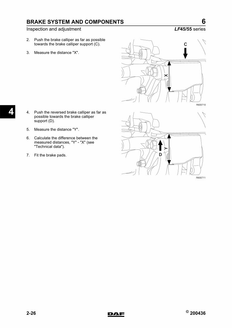
BRAKE SYSTEM AND COMPONENTS
2-26 © 200436
Inspection and adjustment
4
ΛΦ45/55 series6
2. Push the brake calliper as far as possible towards the brake calliper support (C).
3. Measure the distance "X".
4. Push the reversed brake calliper as far as possible towards the brake calliper support (D).
5. Measure the distance "Y".
6. Calculate the difference between the measured distances, "Y" - "X" (see "Technical data").
7. Fit the brake pads.
X
R600710
C
Y
R600711
D
https://www.truck-manuals.net/
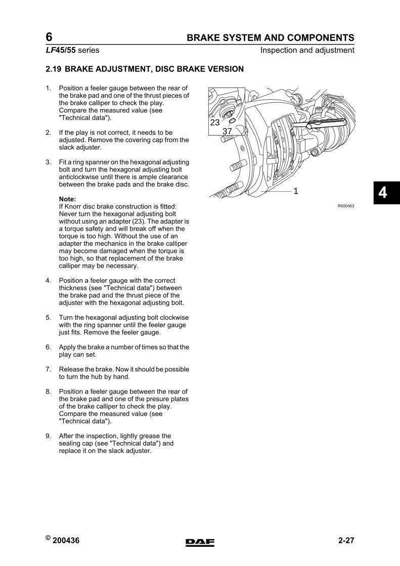
© 200436 2-27
Inspection and adjustmentBRAKE SYSTEM AND COMPONENTS
ΛΦ45/55 series6
4
2.19 BRAKE ADJUSTMENT, DISC BRAKE VERSION
1. Position a feeler gauge between the rear of the brake pad and one of the thrust pieces of the brake calliper to check the play. Compare the measured value (see "Technical data").
2. If the play is not correct, it needs to be adjusted. Remove the covering cap from the slack adjuster.
3. Fit a ring spanner on the hexagonal adjusting bolt and turn the hexagonal adjusting bolt anticlockwise until there is ample clearance between the brake pads and the brake disc.
Note:If Knorr disc brake construction is fitted:Never turn the hexagonal adjusting bolt without using an adapter (23). The adapter is a torque safety and will break off when the torque is too high. Without the use of an adapter the mechanics in the brake calliper may become damaged when the torque is too high, so that replacement of the brake calliper may be necessary.
4. Position a feeler gauge with the correct thickness (see "Technical data") between the brake pad and the thrust piece of the adjuster with the hexagonal adjusting bolt.
5. Turn the hexagonal adjusting bolt clockwise with the ring spanner until the feeler gauge just fits. Remove the feeler gauge.
6. Apply the brake a number of times so that the play can set.
7. Release the brake. Now it should be possible to turn the hub by hand.
8. Position a feeler gauge between the rear of the brake pad and one of the presure plates of the brake calliper to check the play. Compare the measured value (see "Technical data").
9. After the inspection, lightly grease the sealing cap (see "Technical data") and replace it on the slack adjuster.
2337
1
R600463
https://www.truck-manuals.net/
BRAKE SYSTEM AND COMPONENTS
2-28 © 200436
Inspection and adjustment
4
ΛΦ45/55 series6
2.20 INSPECTION, AIR TIGHTNESS
Air tightnessIf the brake system of a vehicle has been charged to the maximum pressure, it should generally be possible to drive the vehicle away after a period of 16 hours of uninterrupted standstill, without first having to charge the brake system to sufficient operating pressure.This implies a maximum pressure drop of approx. 0.4 bar per hour at normal system pressure.
Note:Always connect auxiliary consumers and accessories to circuit 4.
https://www.truck-manuals.net/
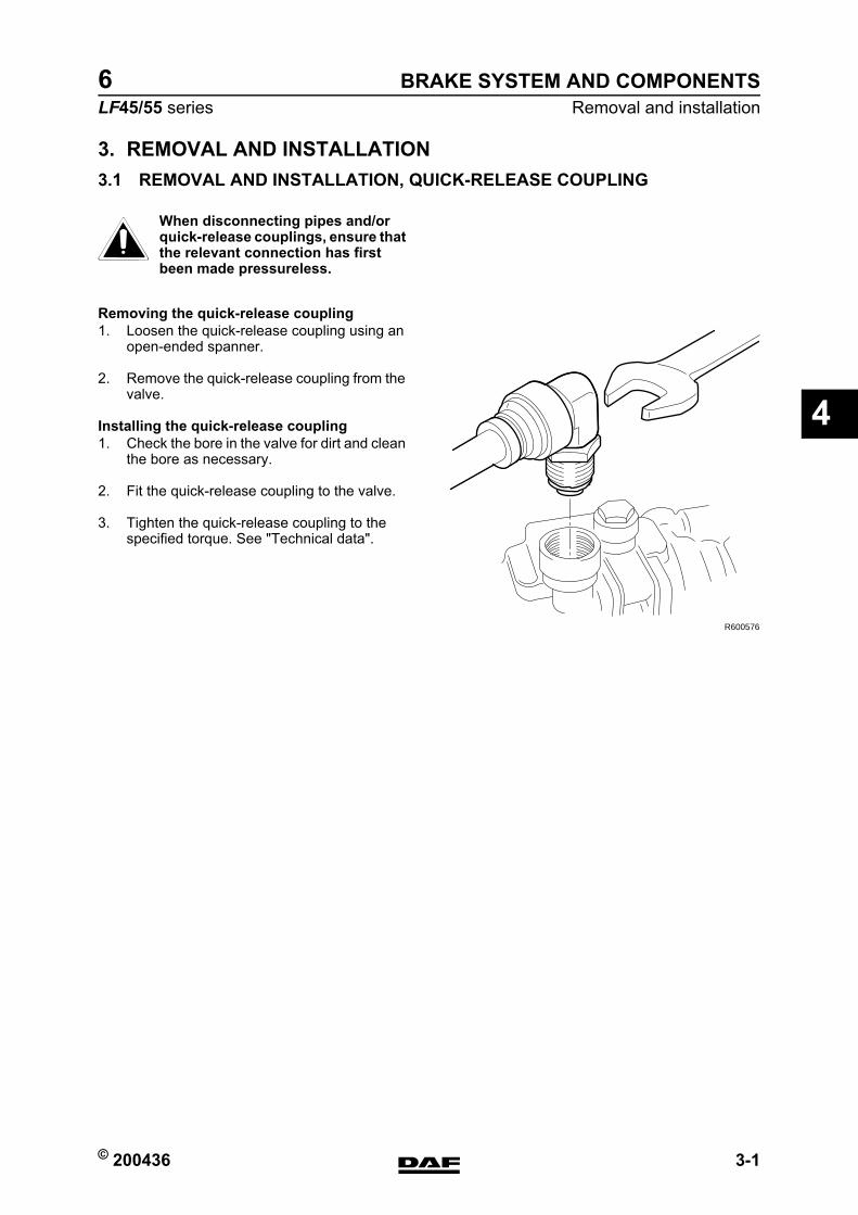
© 200436 3-1
Removal and installationBRAKE SYSTEM AND COMPONENTS
ΛΦ45/55 series6
4
3. REMOVAL AND INSTALLATION3.1 REMOVAL AND INSTALLATION, QUICK-RELEASE COUPLING
When disconnecting pipes and/or quick-release couplings, ensure that the relevant connection has first been made pressureless.
Removing the quick-release coupling1. Loosen the quick-release coupling using an
open-ended spanner.
2. Remove the quick-release coupling from the valve.
Installing the quick-release coupling1. Check the bore in the valve for dirt and clean
the bore as necessary.
2. Fit the quick-release coupling to the valve.
3. Tighten the quick-release coupling to the specified torque. See "Technical data".
}
R600576
https://www.truck-manuals.net/
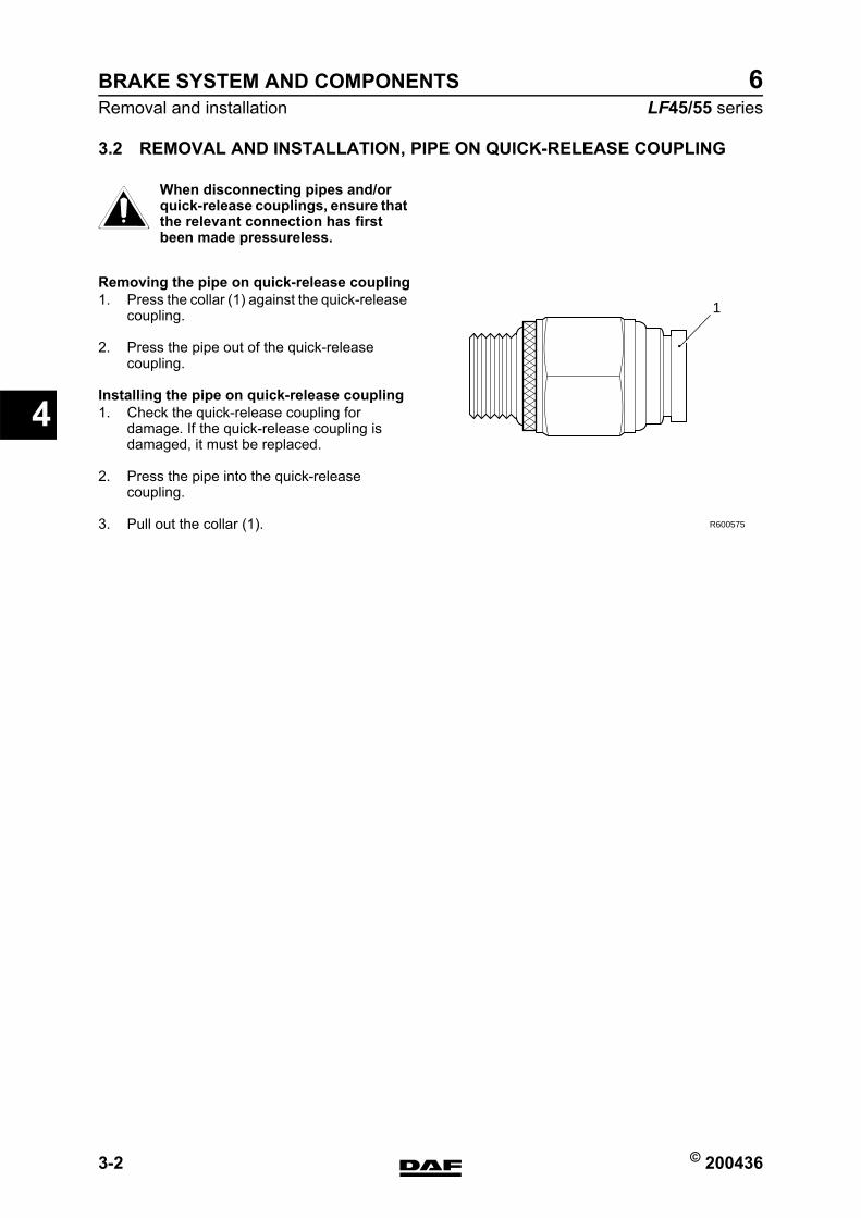
BRAKE SYSTEM AND COMPONENTS
3-2 © 200436
Removal and installation
4
ΛΦ45/55 series6
3.2 REMOVAL AND INSTALLATION, PIPE ON QUICK-RELEASE COUPLING
When disconnecting pipes and/or quick-release couplings, ensure that the relevant connection has first been made pressureless.
Removing the pipe on quick-release coupling1. Press the collar (1) against the quick-release
coupling.
2. Press the pipe out of the quick-release coupling.
Installing the pipe on quick-release coupling1. Check the quick-release coupling for
damage. If the quick-release coupling is damaged, it must be replaced.
2. Press the pipe into the quick-release coupling.
3. Pull out the collar (1).
}
R600575
1
https://www.truck-manuals.net/
© 200436 3-3
Removal and installationBRAKE SYSTEM AND COMPONENTS
ΛΦ45/55 series6
4
3.3 REMOVAL AND INSTALLATION, BRAKE CYLINDER
Removing the brake cylinder1. Remove the compressed air connection to
the brake cylinder.
2. Remove the attachment nuts from the brake cylinder.
3. Remove the brake cylinder.
Installing the brake cylinder1. Fit the brake cylinder onto the support and
tighten the attachment nuts to the specified torque. See "Technical data".
2. Connect the air pipe.
https://www.truck-manuals.net/
BRAKE SYSTEM AND COMPONENTS
3-4 © 200436
Removal and installation
4
ΛΦ45/55 series6
3.4 REMOVAL AND INSTALLATION, SPRING BRAKE CYLINDER
Removing the spring brake cylinder1. Place chocks in front of and behind wheels.
2. Put the parking brake valve in the "Driving" position (provide sufficient system pressure: > 7 bar). Unscrew the spring brake cylinder in the release bolt with a 24-mm spanner as far as possible (anti-clockwise).
3. Place the parking brake valve in the "Parking" position and disconnect the two air pipes from the spring brake cylinder.
4. Remove the attachment nuts and spring washers and remove the spring brake cylinder from the support.
Installing the spring brake cylinder1. Fit the spring brake cylinder onto the support
and tighten the attachment nuts to the specified torque. See "Technical data".
2. Connect the air pipes.
3. Put the parking brake valve in the "Driving" position (provide sufficient system pressure: > 7 bar). Turn the release bolt all the way in and tighten it to the specified torque. See "Technical data".
4. Check the connections for leakage.
https://www.truck-manuals.net/
© 200436 3-5
Removal and installationBRAKE SYSTEM AND COMPONENTS
ΛΦ45/55 series6
4
3.5 REMOVAL AND INSTALLATION, COMPRESSOR CYLINDER HEAD GASKET
Always replace the gaskets when carrying out repairs.
Removing the cylinder head gasket1. Drain some of the coolant.
2. Remove the suction line.
3. Remove the delivery line.
4. Remove the coolant connections.
5. Remove the cylinder head bolts.
6. Remove the cylinder head assembly.
Installing the cylinder head gasket1. Thoroughly clean all parts.
2. Check that there are no remnants on the piston in the compressor.
3. Install the head gasket.
4. Fit the cylinder head including the inlet plate.
5. Insert the cylinder head bolts.
6. Install the suction line.
7. Install the delivery line.
8. Connect the coolant connections.
9. Fill the cooling system.
10. Check the operation of the compressor. See "Inspection and adjustment".
}
https://www.truck-manuals.net/
BRAKE SYSTEM AND COMPONENTS
3-6 © 200436
Removal and installation
4
ΛΦ45/55 series6
3.6 REMOVAL AND INSTALLATION, AIR DRYER FILTER ELEMENT
Note:To be certain that the air dryer is functioning properly, the air reservoirs should regularly be checked for condensation.
If repeatedly more than the normal amount of water is drained off, the filter element will have to be replaced.
Under normal circumstances the element must be replaced at least once per year.
https://www.truck-manuals.net/
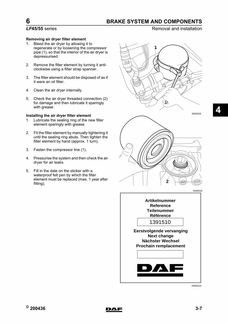
© 200436 3-7
Removal and installationBRAKE SYSTEM AND COMPONENTS
ΛΦ45/55 series6
4
Removing air dryer filter element1. Bleed the air dryer by allowing it to
regenerate or by loosening the compressor pipe (1), so that the interior of the air dryer is depressurised.
2. Remove the filter element by turning it anti-clockwise using a filter strap spanner.
3. The filter element should be disposed of as if it were an oil filter.
4. Clean the air dryer internally.
5. Check the air dryer threaded connection (2) for damage and then lubricate it sparingly with grease.
Installing the air dryer filter element1. Lubricate the sealing ring of the new filter
element sparingly with grease.
2. Fit the filter element by manually tightening it until the sealing ring abuts. Then tighten the filter element by hand (approx. 1 turn).
3. Fasten the compressor line (1).
4. Pressurise the system and then check the air dryer for air leaks.
5. Fill in the date on the sticker with a waterproof felt pen by which the filter element must be replaced (max. 1 year after fitting).
R600525
1
R600526
2
ArtikelnummerReference
TeilenummerRéférence
Eerstvolgende vervangingNext change
Nächster WechselProchain remplacement
1391510
R600523
https://www.truck-manuals.net/
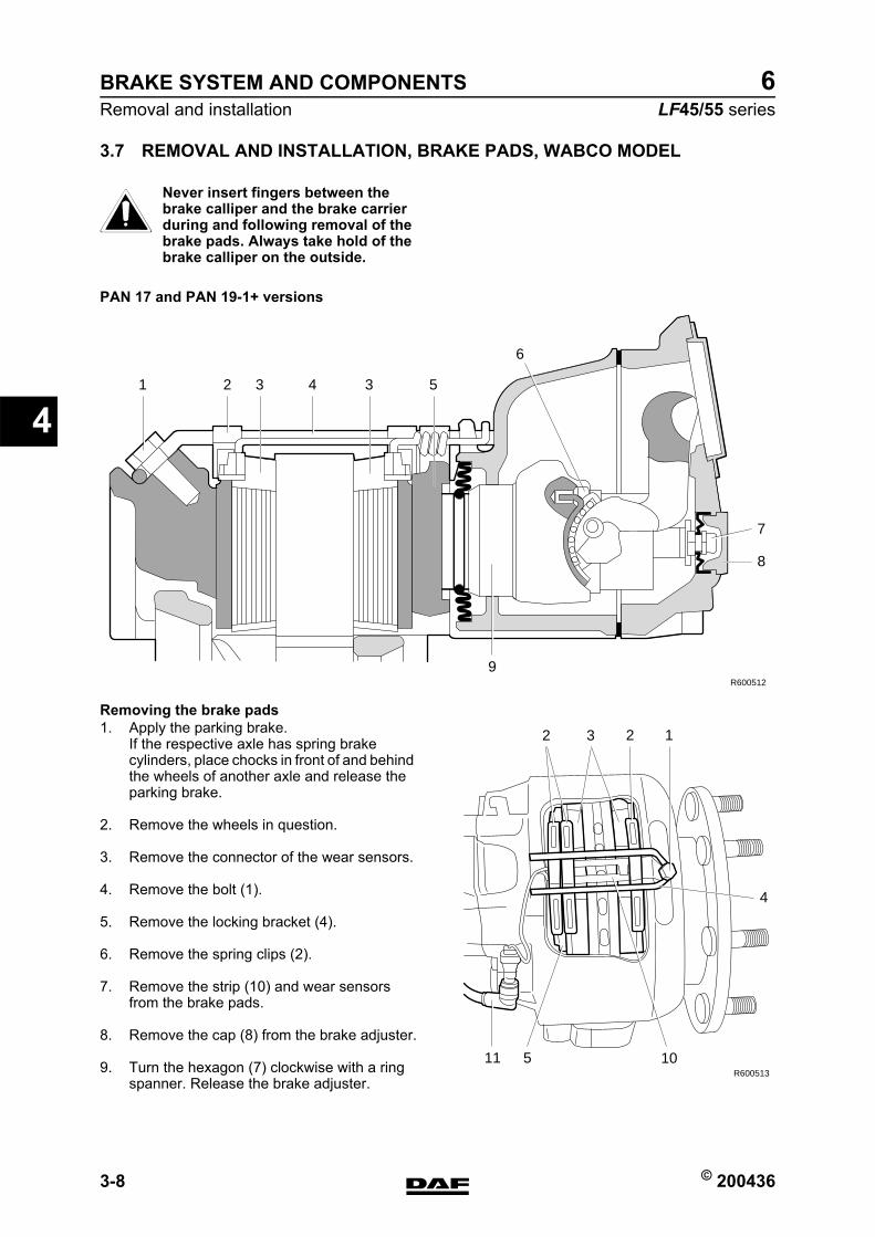
BRAKE SYSTEM AND COMPONENTS
3-8 © 200436
Removal and installation
4
ΛΦ45/55 series6
3.7 REMOVAL AND INSTALLATION, BRAKE PADS, WABCO MODEL
Never insert fingers between the brake calliper and the brake carrier during and following removal of the brake pads. Always take hold of the brake calliper on the outside.
Removing the brake pads1. Apply the parking brake.
If the respective axle has spring brake cylinders, place chocks in front of and behind the wheels of another axle and release the parking brake.
2. Remove the wheels in question.
3. Remove the connector of the wear sensors.
4. Remove the bolt (1).
5. Remove the locking bracket (4).
6. Remove the spring clips (2).
7. Remove the strip (10) and wear sensors from the brake pads.
8. Remove the cap (8) from the brake adjuster.
9. Turn the hexagon (7) clockwise with a ring spanner. Release the brake adjuster.
}PAN 17 and PAN 19-1+ versions
7
8
9R600512
6
533 421
R600513
2 3 2 1
4
10511
https://www.truck-manuals.net/
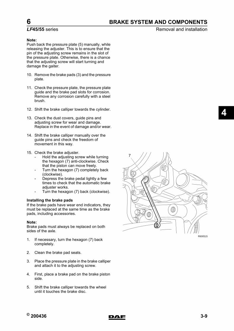
© 200436 3-9
Removal and installationBRAKE SYSTEM AND COMPONENTS
ΛΦ45/55 series6
4
Note:Push back the pressure plate (5) manually, while releasing the adjuster. This is to ensure that the pin of the adjusting screw remains in the slot of the pressure plate. Otherwise, there is a chance that the adjusting screw will start turning and damage the gaiter.
10. Remove the brake pads (3) and the pressure plate.
11. Check the pressure plate, the pressure plate guide and the brake pad slots for corrosion. Remove any corrosion carefully with a steel brush.
12. Shift the brake calliper towards the cylinder.
13. Check the dust covers, guide pins and adjusting screw for wear and damage. Replace in the event of damage and/or wear.
14. Shift the brake calliper manually over the guide pins and check the freedom of movement in this way.
15. Check the brake adjuster.- Hold the adjusting screw while turning
the hexagon (7) anti-clockwise. Check that the piston can move freely.
- Turn the hexagon (7) completely back (clockwise).
- Depress the brake pedal lightly a few times to check that the automatic brake adjuster works.
- Turn the hexagon (7) back (clockwise).
Installing the brake padsIf the brake pads have wear end indicators, they must be replaced at the same time as the brake pads, including accessories.
Note:Brake pads must always be replaced on both sides of the axle.
1. If necessary, turn the hexagon (7) back completely.
2. Clean the brake pad seats.
3. Place the pressure plate in the brake calliper and attach it to the adjusting screw.
4. First, place a brake pad on the brake piston side.
5. Shift the brake calliper towards the wheel until it touches the brake disc.
R600515
7
https://www.truck-manuals.net/
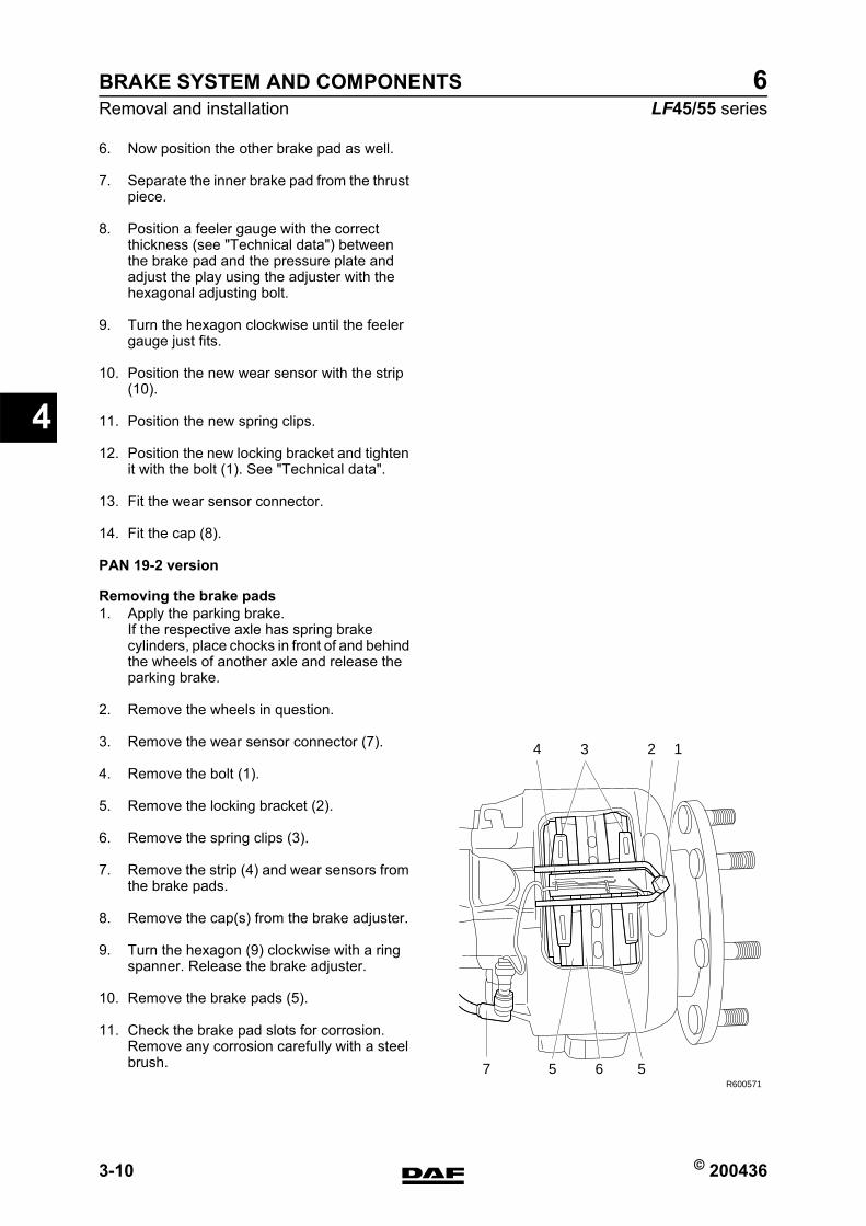
BRAKE SYSTEM AND COMPONENTS
3-10 © 200436
Removal and installation
4
ΛΦ45/55 series6
6. Now position the other brake pad as well.
7. Separate the inner brake pad from the thrust piece.
8. Position a feeler gauge with the correct thickness (see "Technical data") between the brake pad and the pressure plate and adjust the play using the adjuster with the hexagonal adjusting bolt.
9. Turn the hexagon clockwise until the feeler gauge just fits.
10. Position the new wear sensor with the strip (10).
11. Position the new spring clips.
12. Position the new locking bracket and tighten it with the bolt (1). See "Technical data".
13. Fit the wear sensor connector.
14. Fit the cap (8).
PAN 19-2 version
Removing the brake pads1. Apply the parking brake.
If the respective axle has spring brake cylinders, place chocks in front of and behind the wheels of another axle and release the parking brake.
2. Remove the wheels in question.
3. Remove the wear sensor connector (7).
4. Remove the bolt (1).
5. Remove the locking bracket (2).
6. Remove the spring clips (3).
7. Remove the strip (4) and wear sensors from the brake pads.
8. Remove the cap(s) from the brake adjuster.
9. Turn the hexagon (9) clockwise with a ring spanner. Release the brake adjuster.
10. Remove the brake pads (5).
11. Check the brake pad slots for corrosion. Remove any corrosion carefully with a steel brush.
R600571
34 1
5 57
2
6
https://www.truck-manuals.net/
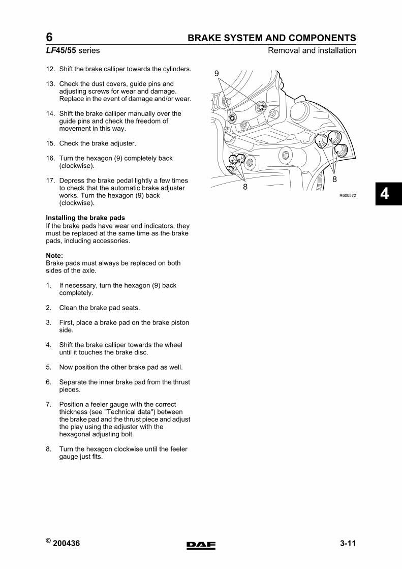
© 200436 3-11
Removal and installationBRAKE SYSTEM AND COMPONENTS
ΛΦ45/55 series6
4
12. Shift the brake calliper towards the cylinders.
13. Check the dust covers, guide pins and adjusting screws for wear and damage. Replace in the event of damage and/or wear.
14. Shift the brake calliper manually over the guide pins and check the freedom of movement in this way.
15. Check the brake adjuster.
16. Turn the hexagon (9) completely back (clockwise).
17. Depress the brake pedal lightly a few times to check that the automatic brake adjuster works. Turn the hexagon (9) back (clockwise).
Installing the brake padsIf the brake pads have wear end indicators, they must be replaced at the same time as the brake pads, including accessories.
Note:Brake pads must always be replaced on both sides of the axle.
1. If necessary, turn the hexagon (9) back completely.
2. Clean the brake pad seats.
3. First, place a brake pad on the brake piston side.
4. Shift the brake calliper towards the wheel until it touches the brake disc.
5. Now position the other brake pad as well.
6. Separate the inner brake pad from the thrust pieces.
7. Position a feeler gauge with the correct thickness (see "Technical data") between the brake pad and the thrust piece and adjust the play using the adjuster with the hexagonal adjusting bolt.
8. Turn the hexagon clockwise until the feeler gauge just fits.
R600572
9
88
https://www.truck-manuals.net/
BRAKE SYSTEM AND COMPONENTS
3-12 © 200436
Removal and installation
4
ΛΦ45/55 series6
9. Position the new wear sensor with the strip (4).
10. Position the new spring clips.
11. Position the new locking bracket and tighten it with the bolt (1). (See "Technical data").
12. Fit the wear sensor connector.
13. Fit the cap(s) to the brake adjuster.
https://www.truck-manuals.net/
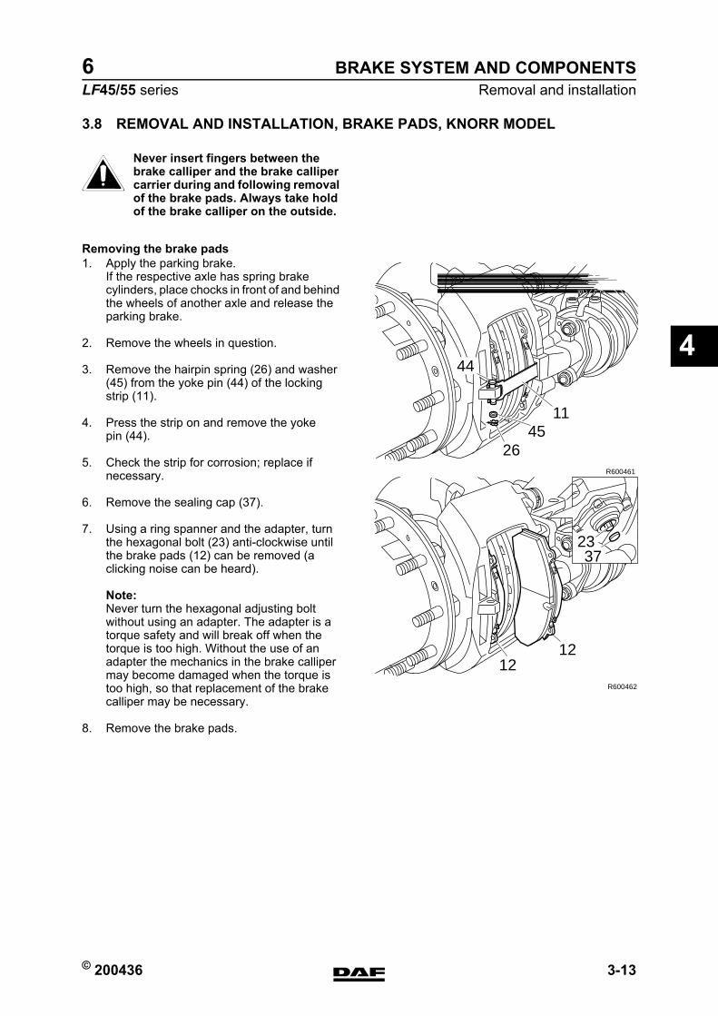
© 200436 3-13
Removal and installationBRAKE SYSTEM AND COMPONENTS
ΛΦ45/55 series6
4
3.8 REMOVAL AND INSTALLATION, BRAKE PADS, KNORR MODEL
Never insert fingers between the brake calliper and the brake calliper carrier during and following removal of the brake pads. Always take hold of the brake calliper on the outside.
Removing the brake pads1. Apply the parking brake.
If the respective axle has spring brake cylinders, place chocks in front of and behind the wheels of another axle and release the parking brake.
2. Remove the wheels in question.
3. Remove the hairpin spring (26) and washer (45) from the yoke pin (44) of the locking strip (11).
4. Press the strip on and remove the yoke pin (44).
5. Check the strip for corrosion; replace if necessary.
6. Remove the sealing cap (37).
7. Using a ring spanner and the adapter, turn the hexagonal bolt (23) anti-clockwise until the brake pads (12) can be removed (a clicking noise can be heard).
Note:Never turn the hexagonal adjusting bolt without using an adapter. The adapter is a torque safety and will break off when the torque is too high. Without the use of an adapter the mechanics in the brake calliper may become damaged when the torque is too high, so that replacement of the brake calliper may be necessary.
8. Remove the brake pads.
}
2645
11
44
R600461
1212
R600462
3723
https://www.truck-manuals.net/
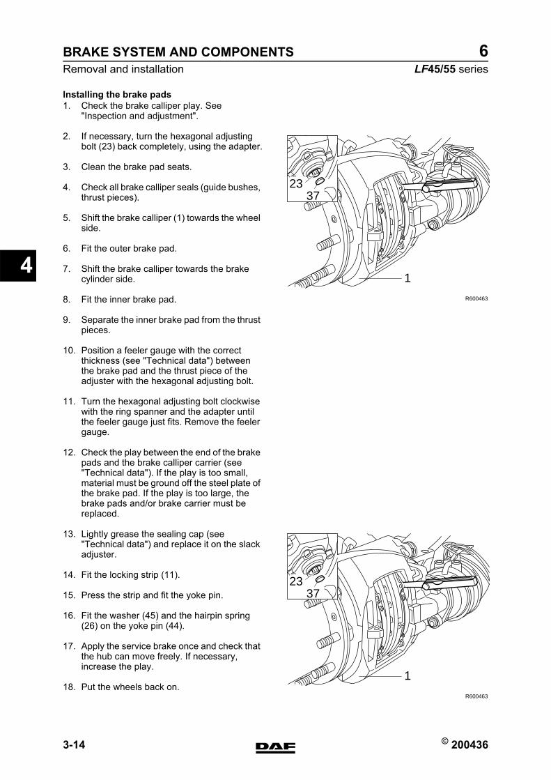
BRAKE SYSTEM AND COMPONENTS
3-14 © 200436
Removal and installation
4
ΛΦ45/55 series6
Installing the brake pads1. Check the brake calliper play. See
"Inspection and adjustment".
2. If necessary, turn the hexagonal adjusting bolt (23) back completely, using the adapter.
3. Clean the brake pad seats.
4. Check all brake calliper seals (guide bushes, thrust pieces).
5. Shift the brake calliper (1) towards the wheel side.
6. Fit the outer brake pad.
7. Shift the brake calliper towards the brake cylinder side.
8. Fit the inner brake pad.
9. Separate the inner brake pad from the thrust pieces.
10. Position a feeler gauge with the correct thickness (see "Technical data") between the brake pad and the thrust piece of the adjuster with the hexagonal adjusting bolt.
11. Turn the hexagonal adjusting bolt clockwise with the ring spanner and the adapter until the feeler gauge just fits. Remove the feeler gauge.
12. Check the play between the end of the brake pads and the brake calliper carrier (see "Technical data"). If the play is too small, material must be ground off the steel plate of the brake pad. If the play is too large, the brake pads and/or brake carrier must be replaced.
13. Lightly grease the sealing cap (see "Technical data") and replace it on the slack adjuster.
14. Fit the locking strip (11).
15. Press the strip and fit the yoke pin.
16. Fit the washer (45) and the hairpin spring (26) on the yoke pin (44).
17. Apply the service brake once and check that the hub can move freely. If necessary, increase the play.
18. Put the wheels back on.
2337
1
R600463
2337
1
R600463
https://www.truck-manuals.net/
© 200436 3-15
Removal and installationBRAKE SYSTEM AND COMPONENTS
ΛΦ45/55 series6
4
3.9 REMOVAL AND INSTALLATION, BRAKE DISC, WABCO MODEL
Removal, brake disc1. Remove the wheel.
2. Remove the brake calliper from the axle.
3. Remove the hub from the axle.
4. Loosen the Allen screws of the brake disc.
5. Remove the brake disc from the hub.
Installation, brake disc1. Clean the contact surfaces between the hub
and the brake disc.
2. Fit the brake disc on the hub.
3. Fit the Allen screws and tighten them to the specified torque. See "Technical data".
4. Fit the hub and brake disc on the axle.
5. Fit the brake calliper.
https://www.truck-manuals.net/

BRAKE SYSTEM AND COMPONENTS
3-16 © 200436
Removal and installation
4
ΛΦ45/55 series6
3.10 REMOVAL AND INSTALLATION, BRAKE DISC, KNORR MODEL
Removal, brake disc1. Remove the hub.
2. Remove the locking plates.
3. Remove the spring plates between the disc and hub and tap the disc off the hub using a copper hammer.If the disc does not come free from the hub, it can be removed by placing it on an old brake drum and pushing it off the hub using a press.
Installation, brake disc1. Remove dirt and corrosion from the contact
surfaces of the brake disc and hub.
2. Position the brake disc on the hub.
3. Fit the spring plates and tighten them to the specified torque. See "Technical data".
https://www.truck-manuals.net/
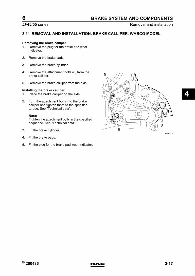
© 200436 3-17
Removal and installationBRAKE SYSTEM AND COMPONENTS
ΛΦ45/55 series6
4
3.11 REMOVAL AND INSTALLATION, BRAKE CALLIPER, WABCO MODEL
Removing the brake calliper1. Remove the plug for the brake pad wear
indicator.
2. Remove the brake pads.
3. Remove the brake cylinder.
4. Remove the attachment bolts (8) from the brake calliper.
5. Remove the brake calliper from the axle.
Installing the brake calliper1. Place the brake calliper on the axle.
2. Turn the attachment bolts into the brake calliper and tighten them to the specified torque. See "Technical data".
Note:Tighten the attachment bolts in the specified sequence. See "Technical data".
3. Fit the brake cylinder.
4. Fit the brake pads.
5. Fit the plug for the brake pad wear indicator.
R600572
9
88
https://www.truck-manuals.net/
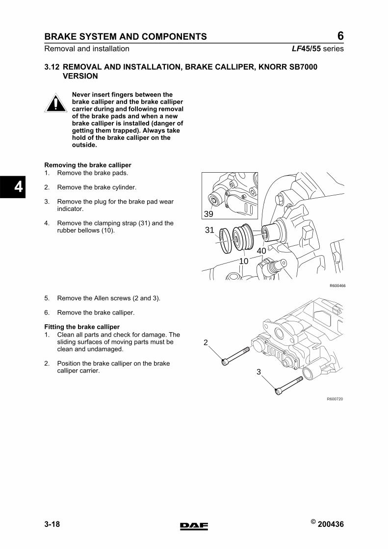
BRAKE SYSTEM AND COMPONENTS
3-18 © 200436
Removal and installation
4
ΛΦ45/55 series6
3.12 REMOVAL AND INSTALLATION, BRAKE CALLIPER, KNORR SB7000 VERSION
Never insert fingers between the brake calliper and the brake calliper carrier during and following removal of the brake pads and when a new brake calliper is installed (danger of getting them trapped). Always take hold of the brake calliper on the outside.
Removing the brake calliper1. Remove the brake pads.
2. Remove the brake cylinder.
3. Remove the plug for the brake pad wear indicator.
4. Remove the clamping strap (31) and the rubber bellows (10).
5. Remove the Allen screws (2 and 3).
6. Remove the brake calliper.
Fitting the brake calliper1. Clean all parts and check for damage. The
sliding surfaces of moving parts must be clean and undamaged.
2. Position the brake calliper on the brake calliper carrier.
}
31
39
R600466
1040
2
3
R600720
https://www.truck-manuals.net/
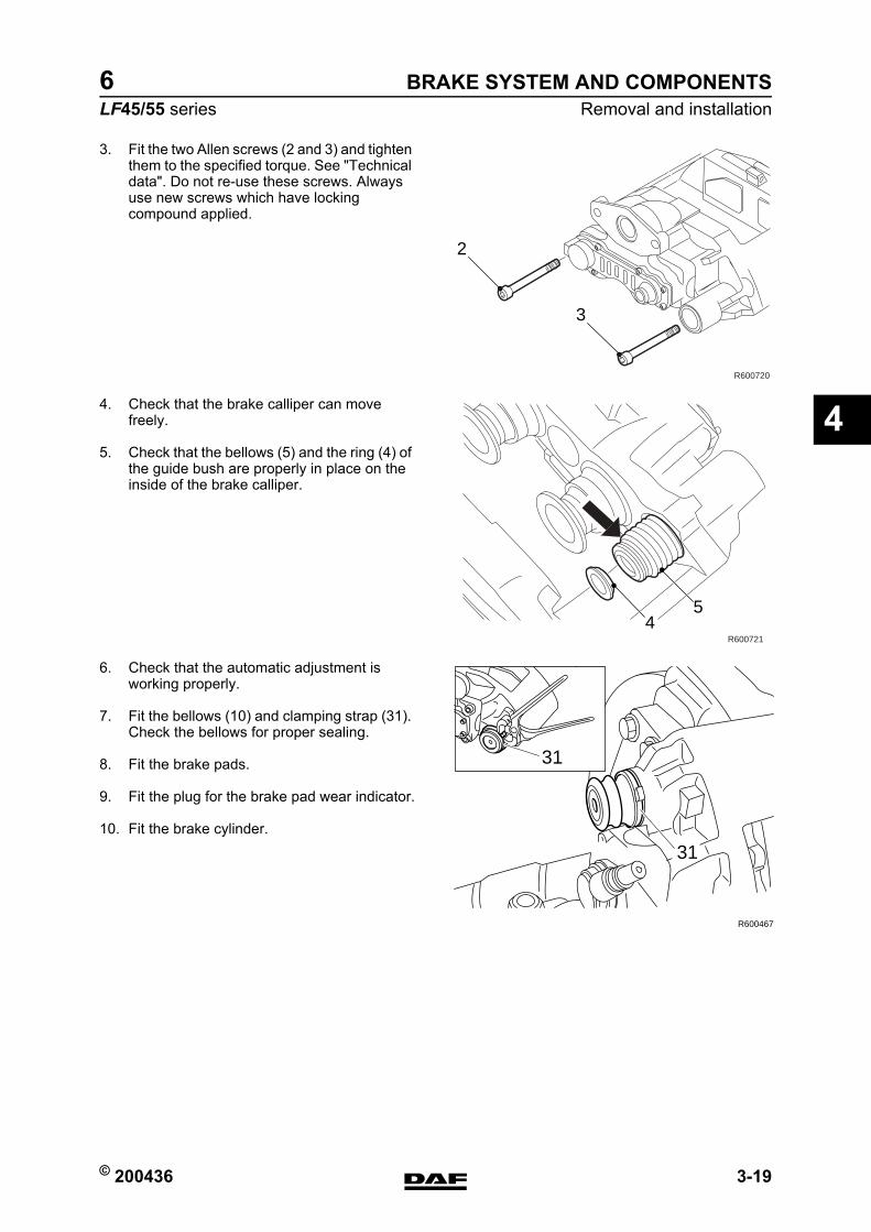
© 200436 3-19
Removal and installationBRAKE SYSTEM AND COMPONENTS
ΛΦ45/55 series6
4
3. Fit the two Allen screws (2 and 3) and tighten them to the specified torque. See "Technical data". Do not re-use these screws. Always use new screws which have locking compound applied.
4. Check that the brake calliper can move freely.
5. Check that the bellows (5) and the ring (4) of the guide bush are properly in place on the inside of the brake calliper.
6. Check that the automatic adjustment is working properly.
7. Fit the bellows (10) and clamping strap (31). Check the bellows for proper sealing.
8. Fit the brake pads.
9. Fit the plug for the brake pad wear indicator.
10. Fit the brake cylinder.
2
3
R600720
R600721
54
39 31
R600467
31
https://www.truck-manuals.net/
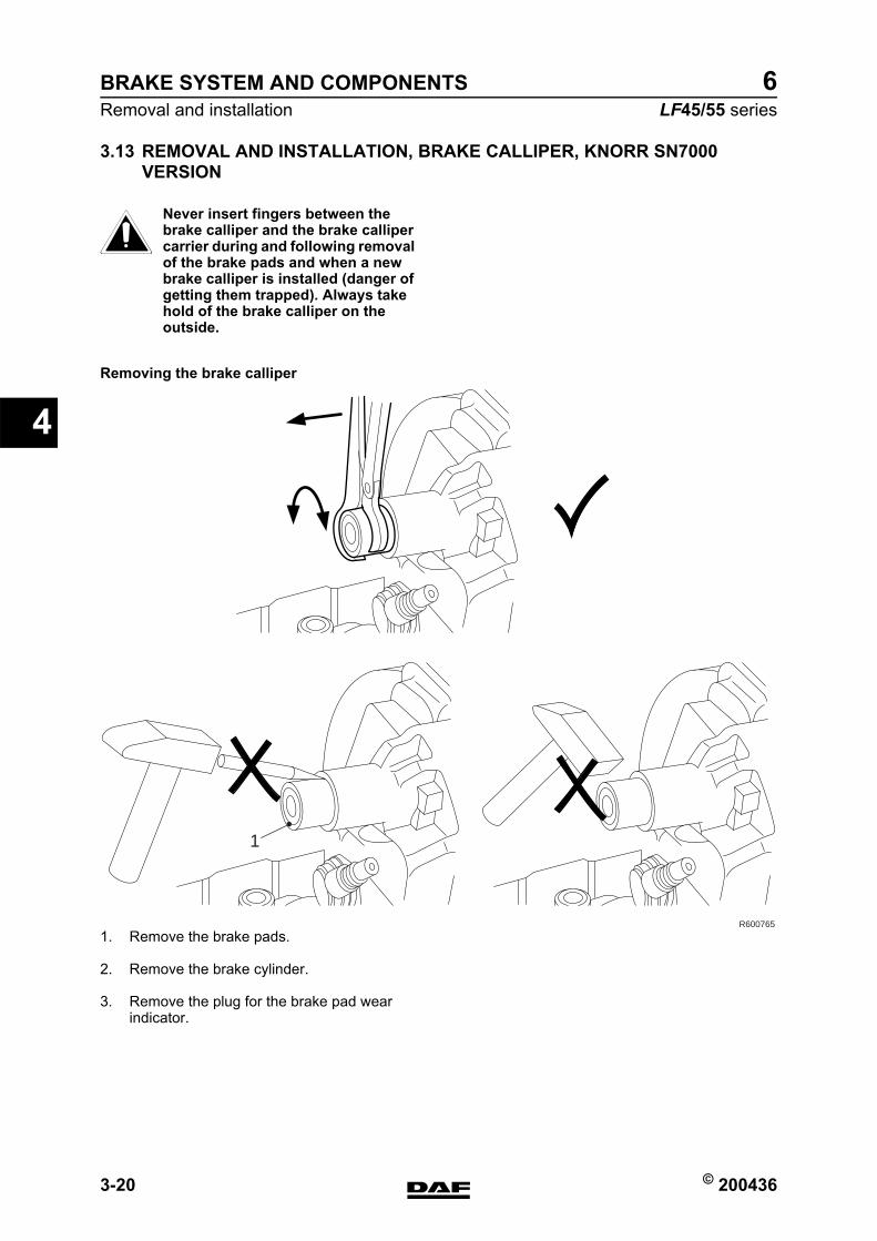
BRAKE SYSTEM AND COMPONENTS
3-20 © 200436
Removal and installation
4
ΛΦ45/55 series6
3.13 REMOVAL AND INSTALLATION, BRAKE CALLIPER, KNORR SN7000 VERSION
Never insert fingers between the brake calliper and the brake calliper carrier during and following removal of the brake pads and when a new brake calliper is installed (danger of getting them trapped). Always take hold of the brake calliper on the outside.
Removing the brake calliper
1. Remove the brake pads.
2. Remove the brake cylinder.
3. Remove the plug for the brake pad wear indicator.
}
R600765
1
https://www.truck-manuals.net/
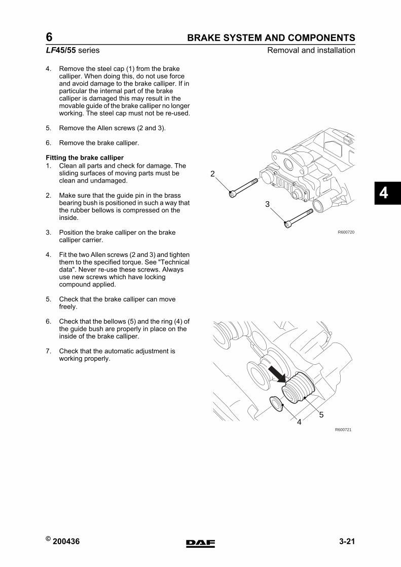
© 200436 3-21
Removal and installationBRAKE SYSTEM AND COMPONENTS
ΛΦ45/55 series6
4
4. Remove the steel cap (1) from the brake calliper. When doing this, do not use force and avoid damage to the brake calliper. If in particular the internal part of the brake calliper is damaged this may result in the movable guide of the brake calliper no longer working. The steel cap must not be re-used.
5. Remove the Allen screws (2 and 3).
6. Remove the brake calliper.
Fitting the brake calliper1. Clean all parts and check for damage. The
sliding surfaces of moving parts must be clean and undamaged.
2. Make sure that the guide pin in the brass bearing bush is positioned in such a way that the rubber bellows is compressed on the inside.
3. Position the brake calliper on the brake calliper carrier.
4. Fit the two Allen screws (2 and 3) and tighten them to the specified torque. See "Technical data". Never re-use these screws. Always use new screws which have locking compound applied.
5. Check that the brake calliper can move freely.
6. Check that the bellows (5) and the ring (4) of the guide bush are properly in place on the inside of the brake calliper.
7. Check that the automatic adjustment is working properly.
2
3
R600720
R600721
54
https://www.truck-manuals.net/
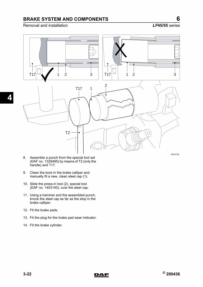
BRAKE SYSTEM AND COMPONENTS
3-22 © 200436
Removal and installation
4
ΛΦ45/55 series6
8. Assemble a punch from the special tool set (DAF no. 1329495) by means of T2 (only the handle) and T17.
9. Clean the bore in the brake calliper and manually fit a new, clean steel cap (1).
10. Slide the press-in tool (2), special tool (DAF no. 1453140), over the steel cap.
11. Using a hammer and the assembled punch, knock the steel cap as far as the stop in the brake calliper.
12. Fit the brake pads.
13. Fit the plug for the brake pad wear indicator.
14. Fit the brake cylinder.
R600766
31T17
T17
T2
T17 1 2 3
12
2
https://www.truck-manuals.net/
© 200436 3-23
Removal and installationBRAKE SYSTEM AND COMPONENTS
ΛΦ45/55 series6
4
3.14 REMOVAL AND INSTALLATION, BRAKE CALLIPER CARRIER
Removing brake calliper carrier1. Remove the brake calliper.
2. Remove the attachment bolts from the brake calliper carrier.
3. Remove the brake calliper carrier.
Fitting the brake calliper carrier1. Clean the brake calliper carrier and the
contact surfaces of the stub axle or brake back plate. Pay particular attention to the threaded holes and sliding surfaces of the brake pads.
2. Fit the brake calliper carrier against the stub axle or brake back plate.
3. Fit the attachment bolts and tighten to the specified torque. See "Technical data".
Note:Starting in production week 2002-25, the attachment of the brake calliper against the stub axle (front axles) may have been changed on models with disc brakes. Five bolts are now used instead of six bolts. The bolt hole for the "6th bolt" is then still fitted in the brake calliper carrier, but not in the stub axle.
https://www.truck-manuals.net/
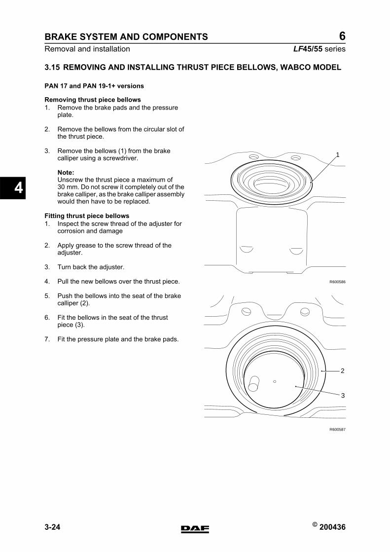
BRAKE SYSTEM AND COMPONENTS
3-24 © 200436
Removal and installation
4
ΛΦ45/55 series6
3.15 REMOVING AND INSTALLING THRUST PIECE BELLOWS, WABCO MODEL
PAN 17 and PAN 19-1+ versions
Removing thrust piece bellows1. Remove the brake pads and the pressure
plate.
2. Remove the bellows from the circular slot of the thrust piece.
3. Remove the bellows (1) from the brake calliper using a screwdriver.
Note:Unscrew the thrust piece a maximum of 30 mm. Do not screw it completely out of the brake calliper, as the brake calliper assembly would then have to be replaced.
Fitting thrust piece bellows1. Inspect the screw thread of the adjuster for
corrosion and damage
2. Apply grease to the screw thread of the adjuster.
3. Turn back the adjuster.
4. Pull the new bellows over the thrust piece.
5. Push the bellows into the seat of the brake calliper (2).
6. Fit the bellows in the seat of the thrust piece (3).
7. Fit the pressure plate and the brake pads.
R600586
1
R600587
2
3
https://www.truck-manuals.net/
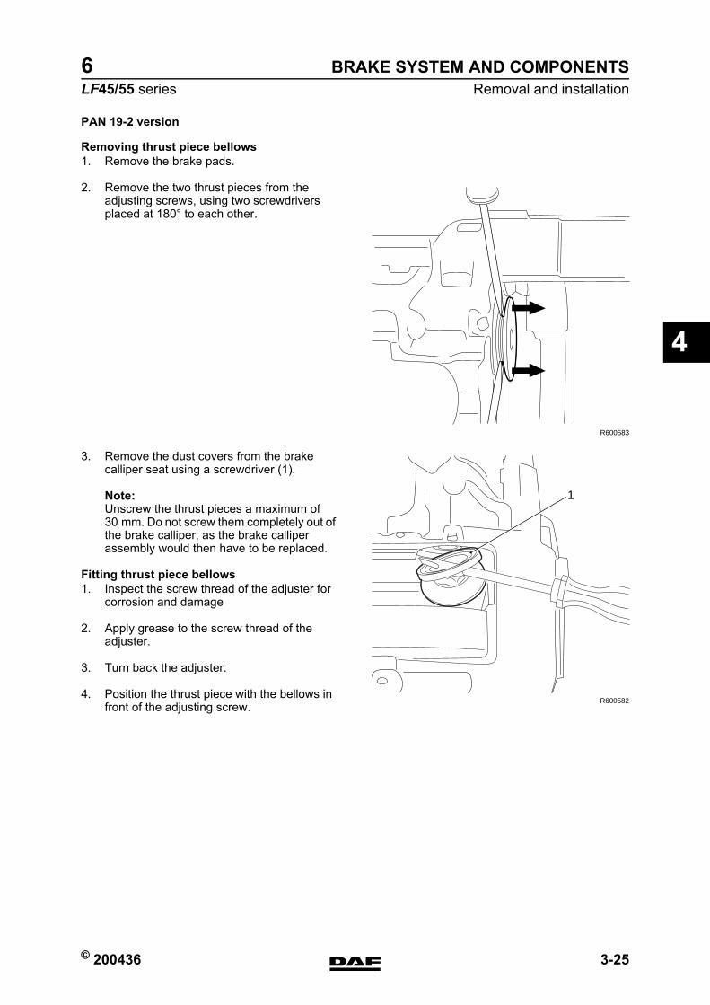
© 200436 3-25
Removal and installationBRAKE SYSTEM AND COMPONENTS
ΛΦ45/55 series6
4
PAN 19-2 version
Removing thrust piece bellows1. Remove the brake pads.
2. Remove the two thrust pieces from the adjusting screws, using two screwdrivers placed at 180 to each other.
3. Remove the dust covers from the brake calliper seat using a screwdriver (1).
Note:Unscrew the thrust pieces a maximum of 30 mm. Do not screw them completely out of the brake calliper, as the brake calliper assembly would then have to be replaced.
Fitting thrust piece bellows1. Inspect the screw thread of the adjuster for
corrosion and damage
2. Apply grease to the screw thread of the adjuster.
3. Turn back the adjuster.
4. Position the thrust piece with the bellows in front of the adjusting screw.
R600583
R600582
1
https://www.truck-manuals.net/
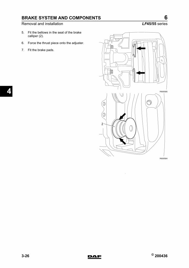
BRAKE SYSTEM AND COMPONENTS
3-26 © 200436
Removal and installation
4
ΛΦ45/55 series6
5. Fit the bellows in the seat of the brake calliper (2).
6. Force the thrust piece onto the adjuster.
7. Fit the brake pads.
R600585
R600584
2
https://www.truck-manuals.net/
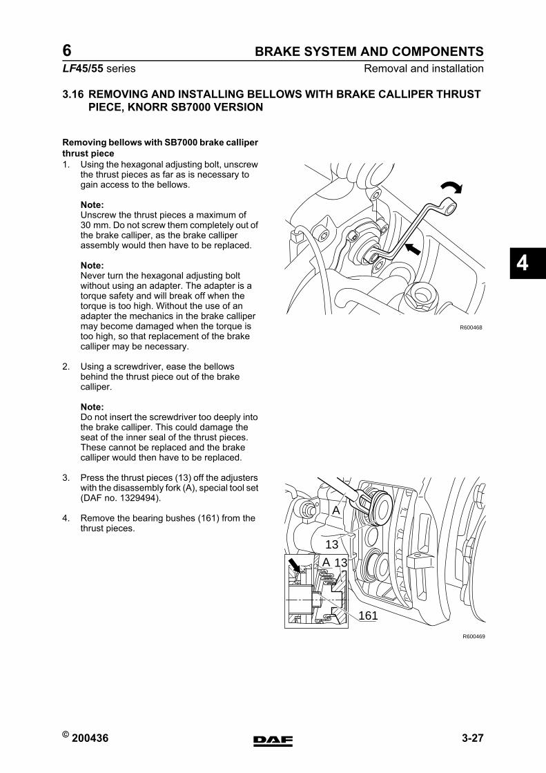
© 200436 3-27
Removal and installationBRAKE SYSTEM AND COMPONENTS
ΛΦ45/55 series6
4
3.16 REMOVING AND INSTALLING BELLOWS WITH BRAKE CALLIPER THRUST PIECE, KNORR SB7000 VERSION
Removing bellows with SB7000 brake calliper thrust piece1. Using the hexagonal adjusting bolt, unscrew
the thrust pieces as far as is necessary to gain access to the bellows.
Note:Unscrew the thrust pieces a maximum of 30 mm. Do not screw them completely out of the brake calliper, as the brake calliper assembly would then have to be replaced.
Note:Never turn the hexagonal adjusting bolt without using an adapter. The adapter is a torque safety and will break off when the torque is too high. Without the use of an adapter the mechanics in the brake calliper may become damaged when the torque is too high, so that replacement of the brake calliper may be necessary.
2. Using a screwdriver, ease the bellows behind the thrust piece out of the brake calliper.
Note:Do not insert the screwdriver too deeply into the brake calliper. This could damage the seat of the inner seal of the thrust pieces. These cannot be replaced and the brake calliper would then have to be replaced.
3. Press the thrust pieces (13) off the adjusters with the disassembly fork (A), special tool set (DAF no. 1329494).
4. Remove the bearing bushes (161) from the thrust pieces.
R600468
A 13
13
R600469
161
A
https://www.truck-manuals.net/
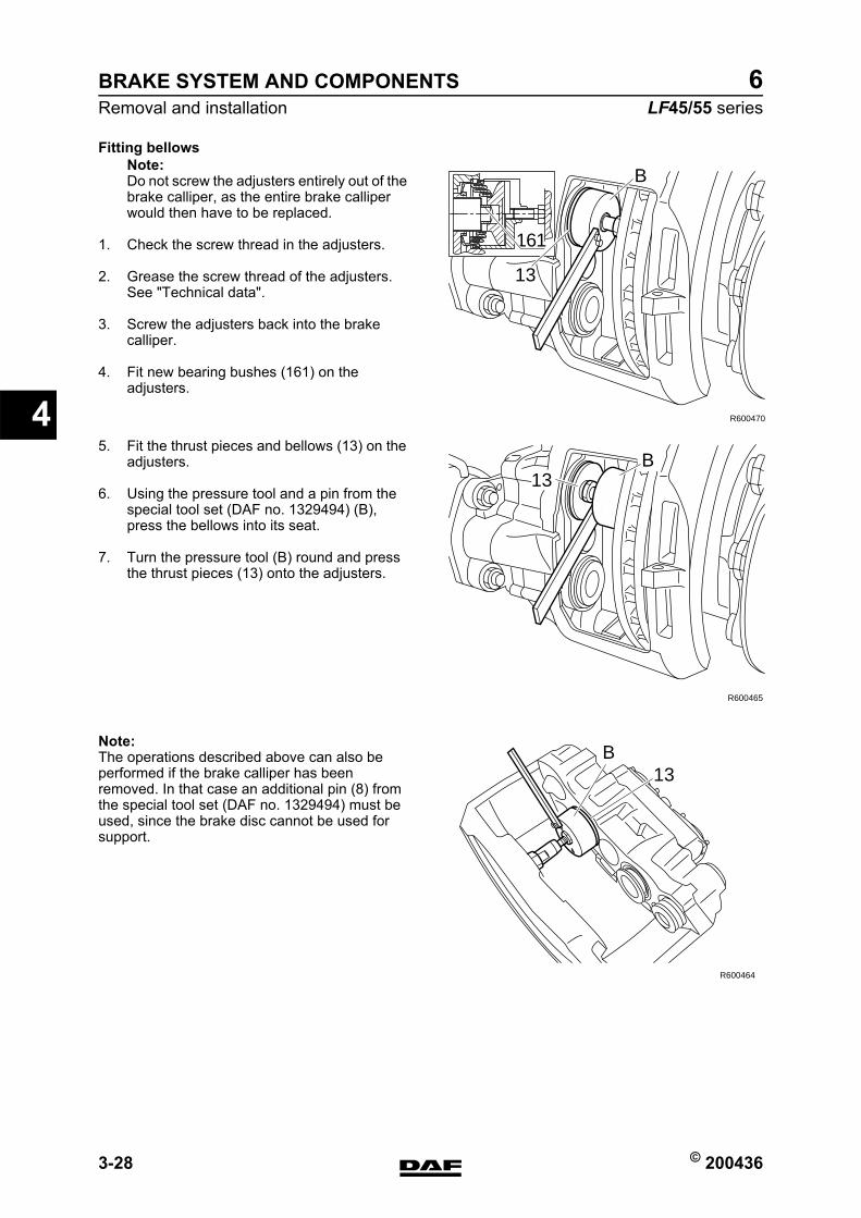
BRAKE SYSTEM AND COMPONENTS
3-28 © 200436
Removal and installation
4
ΛΦ45/55 series6
Fitting bellowsNote:Do not screw the adjusters entirely out of the brake calliper, as the entire brake calliper would then have to be replaced.
1. Check the screw thread in the adjusters.
2. Grease the screw thread of the adjusters. See "Technical data".
3. Screw the adjusters back into the brake calliper.
4. Fit new bearing bushes (161) on the adjusters.
5. Fit the thrust pieces and bellows (13) on the adjusters.
6. Using the pressure tool and a pin from the special tool set (DAF no. 1329494) (B), press the bellows into its seat.
7. Turn the pressure tool (B) round and press the thrust pieces (13) onto the adjusters.
Note:The operations described above can also be performed if the brake calliper has been removed. In that case an additional pin (8) from the special tool set (DAF no. 1329494) must be used, since the brake disc cannot be used for support.
B
13
161
R600470
B13
R600465
B13
R600464
https://www.truck-manuals.net/
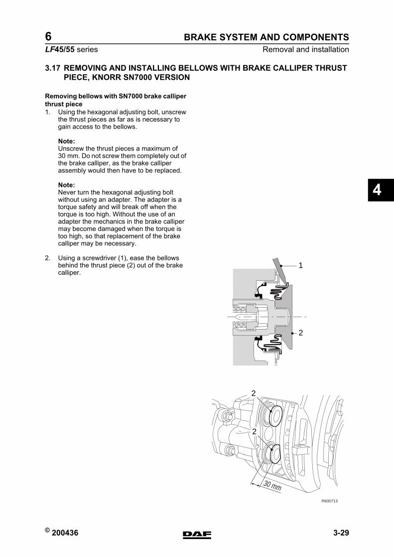
© 200436 3-29
Removal and installationBRAKE SYSTEM AND COMPONENTS
ΛΦ45/55 series6
4
3.17 REMOVING AND INSTALLING BELLOWS WITH BRAKE CALLIPER THRUST PIECE, KNORR SN7000 VERSION
Removing bellows with SN7000 brake calliper thrust piece1. Using the hexagonal adjusting bolt, unscrew
the thrust pieces as far as is necessary to gain access to the bellows.
Note:Unscrew the thrust pieces a maximum of 30 mm. Do not screw them completely out of the brake calliper, as the brake calliper assembly would then have to be replaced.
Note:Never turn the hexagonal adjusting bolt without using an adapter. The adapter is a torque safety and will break off when the torque is too high. Without the use of an adapter the mechanics in the brake calliper may become damaged when the torque is too high, so that replacement of the brake calliper may be necessary.
2. Using a screwdriver (1), ease the bellows behind the thrust piece (2) out of the brake calliper.
30 mm
2
2
1
2
R600713
https://www.truck-manuals.net/
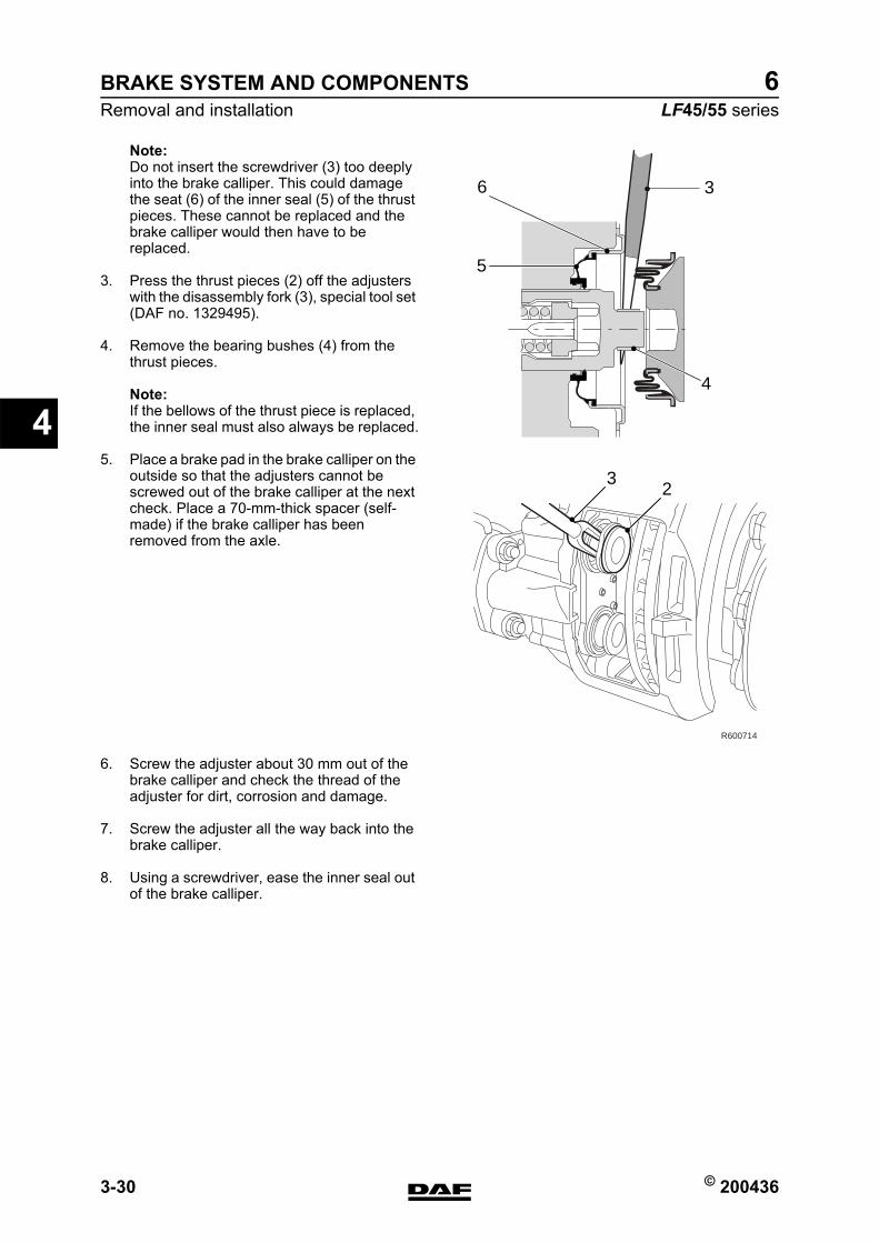
BRAKE SYSTEM AND COMPONENTS
3-30 © 200436
Removal and installation
4
ΛΦ45/55 series6
Note:Do not insert the screwdriver (3) too deeply into the brake calliper. This could damage the seat (6) of the inner seal (5) of the thrust pieces. These cannot be replaced and the brake calliper would then have to be replaced.
3. Press the thrust pieces (2) off the adjusters with the disassembly fork (3), special tool set (DAF no. 1329495).
4. Remove the bearing bushes (4) from the thrust pieces.
Note:If the bellows of the thrust piece is replaced, the inner seal must also always be replaced.
5. Place a brake pad in the brake calliper on the outside so that the adjusters cannot be screwed out of the brake calliper at the next check. Place a 70-mm-thick spacer (self-made) if the brake calliper has been removed from the axle.
6. Screw the adjuster about 30 mm out of the brake calliper and check the thread of the adjuster for dirt, corrosion and damage.
7. Screw the adjuster all the way back into the brake calliper.
8. Using a screwdriver, ease the inner seal out of the brake calliper.
R600714
23
3
5
6
4
https://www.truck-manuals.net/

© 200436 3-31
Removal and installationBRAKE SYSTEM AND COMPONENTS
ΛΦ45/55 series6
4
Fitting bellows with SN7000 brake calliper thrust piece1. Clean the adjuster.
2. Fit the new inner seal (1) on the adjuster.
R600715
3
321
https://www.truck-manuals.net/
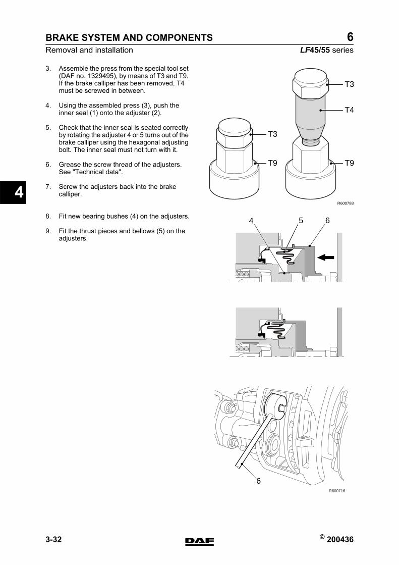
BRAKE SYSTEM AND COMPONENTS
3-32 © 200436
Removal and installation
4
ΛΦ45/55 series6
3. Assemble the press from the special tool set (DAF no. 1329495), by means of T3 and T9. If the brake calliper has been removed, T4 must be screwed in between.
4. Using the assembled press (3), push the inner seal (1) onto the adjuster (2).
5. Check that the inner seal is seated correctly by rotating the adjuster 4 or 5 turns out of the brake calliper using the hexagonal adjusting bolt. The inner seal must not turn with it.
6. Grease the screw thread of the adjusters. See "Technical data".
7. Screw the adjusters back into the brake calliper.
8. Fit new bearing bushes (4) on the adjusters.
9. Fit the thrust pieces and bellows (5) on the adjusters.
T9
R600788
T4
T3
T9
T3
R600716
654
6
https://www.truck-manuals.net/
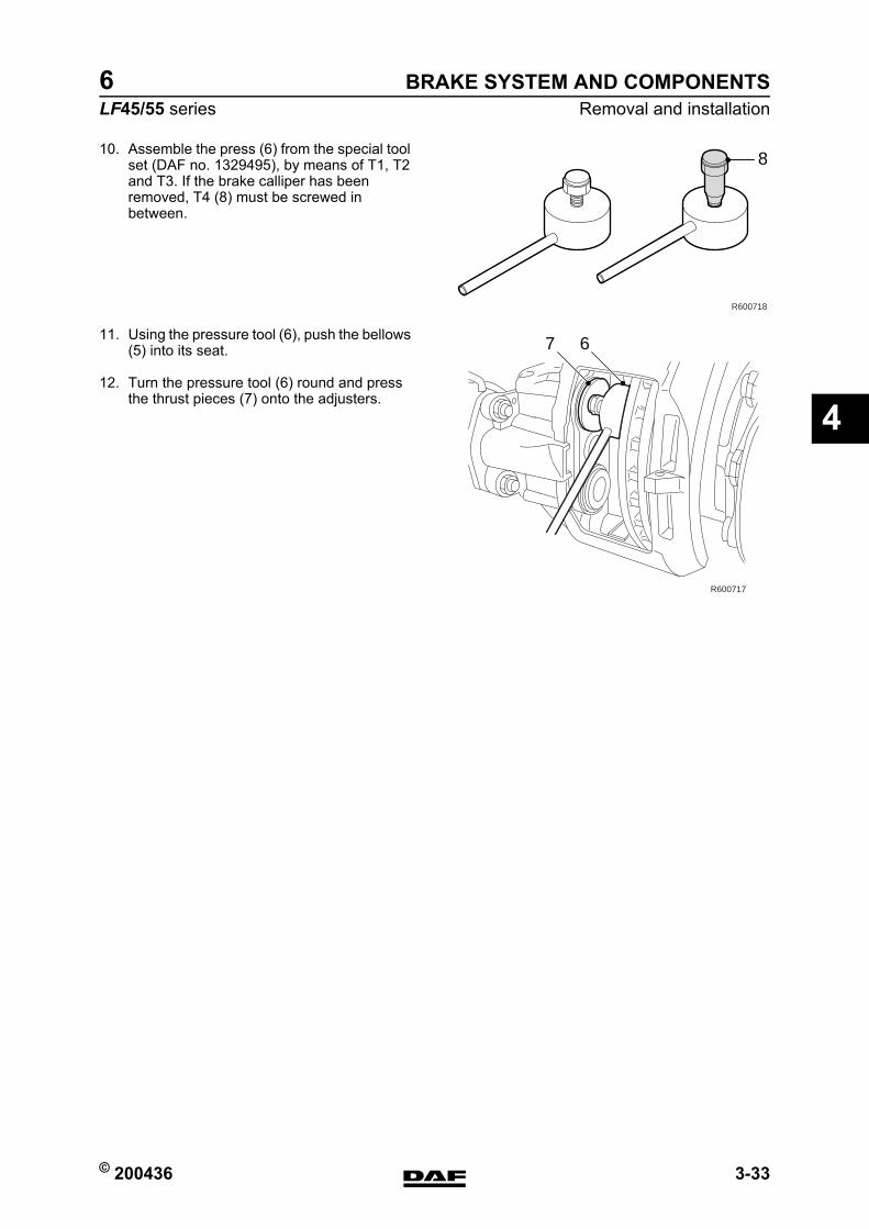
© 200436 3-33
Removal and installationBRAKE SYSTEM AND COMPONENTS
ΛΦ45/55 series6
4
10. Assemble the press (6) from the special tool set (DAF no. 1329495), by means of T1, T2 and T3. If the brake calliper has been removed, T4 (8) must be screwed in between.
11. Using the pressure tool (6), push the bellows (5) into its seat.
12. Turn the pressure tool (6) round and press the thrust pieces (7) onto the adjusters.
R600718
8
R600717
7 6
https://www.truck-manuals.net/
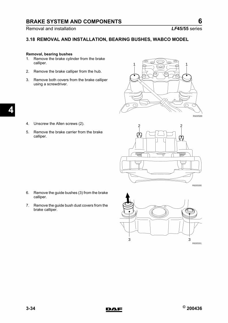
BRAKE SYSTEM AND COMPONENTS
3-34 © 200436
Removal and installation
4
ΛΦ45/55 series6
3.18 REMOVAL AND INSTALLATION, BEARING BUSHES, WABCO MODEL
Removal, bearing bushes1. Remove the brake cylinder from the brake
calliper.
2. Remove the brake calliper from the hub.
3. Remove both covers from the brake calliper using a screwdriver.
4. Unscrew the Allen screws (2).
5. Remove the brake carrier from the brake calliper.
6. Remove the guide bushes (3) from the brake calliper.
7. Remove the guide bush dust covers from the brake calliper.
R600589
11
R600590
22
R6005913 3
https://www.truck-manuals.net/
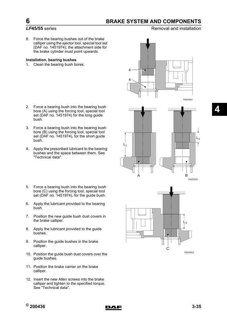
© 200436 3-35
Removal and installationBRAKE SYSTEM AND COMPONENTS
ΛΦ45/55 series6
4
8. Force the bearing bushes out of the brake calliper using the ejector tool, special tool set (DAF no. 1451974); the attachment side for the brake cylinder must point upwards.
Installation, bearing bushes1. Clean the bearing bush bores.
2. Force a bearing bush into the bearing bush bore (A) using the forcing tool, special tool set (DAF no. 1451974) for the long guide bush.
3. Force a bearing bush into the bearing bush bore (B) using the forcing tool, special tool set (DAF no. 1451974), for the short guide bush.
4. Apply the prescribed lubricant to the bearing bushes and the space between them. See "Technical data".
5. Force a bearing bush into the bearing bush bore (C) using the forcing tool, special tool set (DAF no. 1451974), for the guide bush.
6. Apply the lubricant provided to the bearing bush.
7. Position the new guide bush dust covers in the brake calliper.
8. Apply the lubricant provided to the guide bushes.
9. Position the guide bushes in the brake calliper.
10. Position the guide bush dust covers over the guide bushes.
11. Position the brake carrier on the brake calliper.
12. Insert the new Allen screws into the brake calliper and tighten to the specified torque. See "Technical data".
4
4
R600592
R600593
L1
L2
A B
R600603
L3
C
https://www.truck-manuals.net/
BRAKE SYSTEM AND COMPONENTS
3-36 © 200436
Removal and installation
4
ΛΦ45/55 series6
Note:To prevent damage to the guide bush dust covers, the Allen screw of the long guide bush must be tightened first.
13. Check the brake carrier guide and the brake calliper in relation to each other.
14. Position the new covers in the brake calliper.
15. Mount the brake calliper on the hub.
16. Mount the brake cylinder on the brake calliper.
https://www.truck-manuals.net/
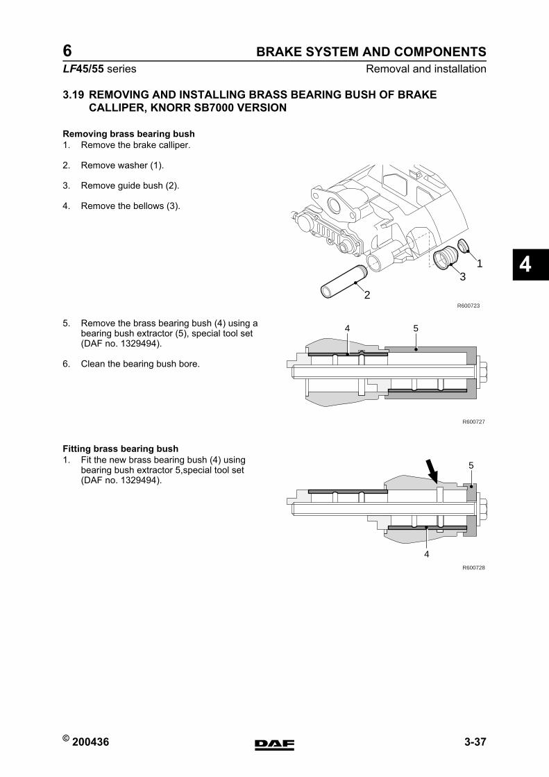
© 200436 3-37
Removal and installationBRAKE SYSTEM AND COMPONENTS
ΛΦ45/55 series6
4
3.19 REMOVING AND INSTALLING BRASS BEARING BUSH OF BRAKE CALLIPER, KNORR SB7000 VERSION
Removing brass bearing bush1. Remove the brake calliper.
2. Remove washer (1).
3. Remove guide bush (2).
4. Remove the bellows (3).
5. Remove the brass bearing bush (4) using a bearing bush extractor (5), special tool set (DAF no. 1329494).
6. Clean the bearing bush bore.
Fitting brass bearing bush1. Fit the new brass bearing bush (4) using
bearing bush extractor 5,special tool set (DAF no. 1329494).
2
31
R600723
R600727
4 5
R600728
4
5
https://www.truck-manuals.net/
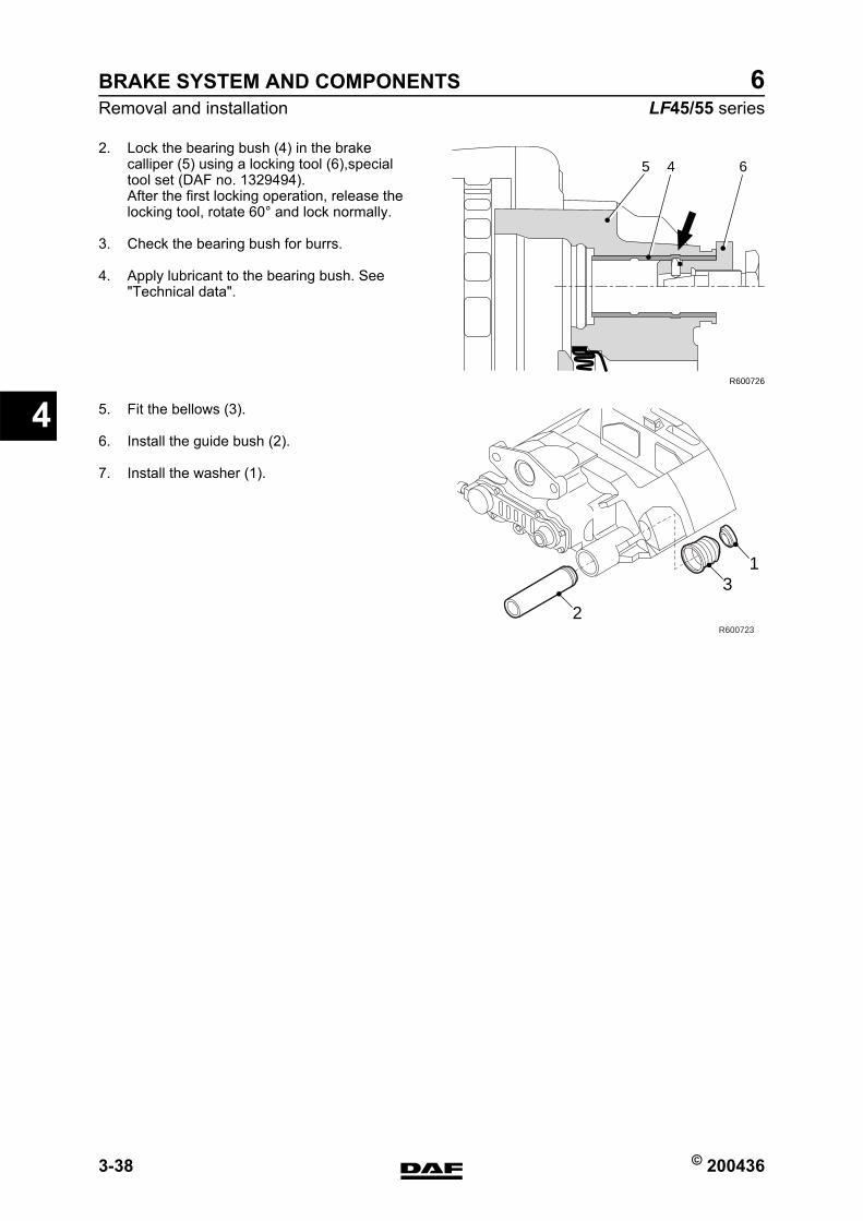
BRAKE SYSTEM AND COMPONENTS
3-38 © 200436
Removal and installation
4
ΛΦ45/55 series6
2. Lock the bearing bush (4) in the brake calliper (5) using a locking tool (6),special tool set (DAF no. 1329494).After the first locking operation, release the locking tool, rotate 60 and lock normally.
3. Check the bearing bush for burrs.
4. Apply lubricant to the bearing bush. See "Technical data".
5. Fit the bellows (3).
6. Install the guide bush (2).
7. Install the washer (1).
65 4
R600726
2
31
R600723
https://www.truck-manuals.net/
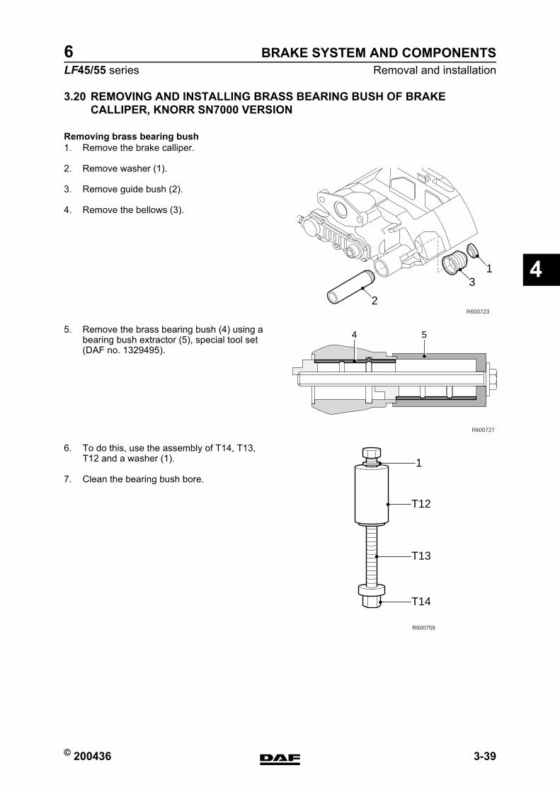
© 200436 3-39
Removal and installationBRAKE SYSTEM AND COMPONENTS
ΛΦ45/55 series6
4
3.20 REMOVING AND INSTALLING BRASS BEARING BUSH OF BRAKE CALLIPER, KNORR SN7000 VERSION
Removing brass bearing bush1. Remove the brake calliper.
2. Remove washer (1).
3. Remove guide bush (2).
4. Remove the bellows (3).
5. Remove the brass bearing bush (4) using a bearing bush extractor (5), special tool set (DAF no. 1329495).
6. To do this, use the assembly of T14, T13, T12 and a washer (1).
7. Clean the bearing bush bore.
2
31
R600723
R600727
4 5
T12
T13
T14
R600759
1
https://www.truck-manuals.net/

BRAKE SYSTEM AND COMPONENTS
3-40 © 200436
Removal and installation
4
ΛΦ45/55 series6
Fitting brass bearing bush1. Fit the new brass bearing bush (4) using
bearing bush extractor 5,special tool set (DAF no. 1329495).
2. To do this, use the assembly of T16, T13, T8, T14 and a washer (1).
R600728
4
5
1
T14
T8
T13
T16
R600760
https://www.truck-manuals.net/
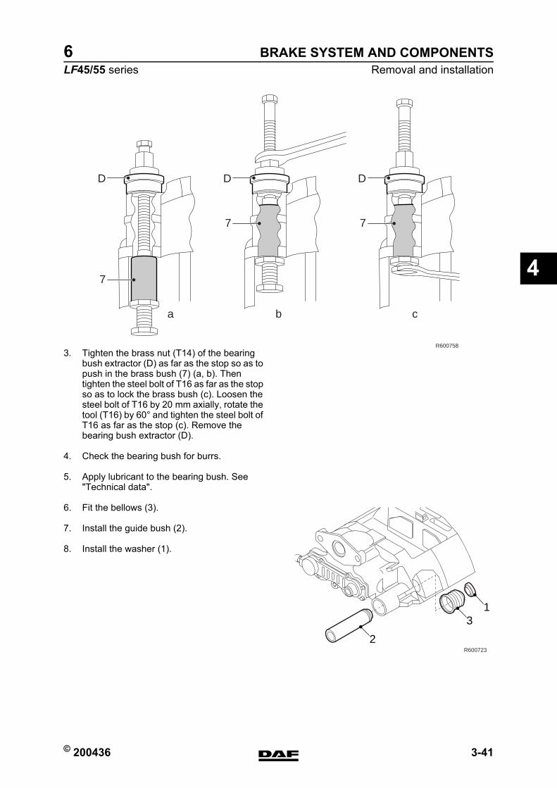
© 200436 3-41
Removal and installationBRAKE SYSTEM AND COMPONENTS
ΛΦ45/55 series6
4
3. Tighten the brass nut (T14) of the bearing bush extractor (D) as far as the stop so as to push in the brass bush (7) (a, b). Then tighten the steel bolt of T16 as far as the stop so as to lock the brass bush (c). Loosen the steel bolt of T16 by 20 mm axially, rotate the tool (T16) by 60 and tighten the steel bolt of T16 as far as the stop (c). Remove the bearing bush extractor (D).
4. Check the bearing bush for burrs.
5. Apply lubricant to the bearing bush. See "Technical data".
6. Fit the bellows (3).
7. Install the guide bush (2).
8. Install the washer (1).
R600758
D
ba c
7
D
7
D
7
2
31
R600723
https://www.truck-manuals.net/
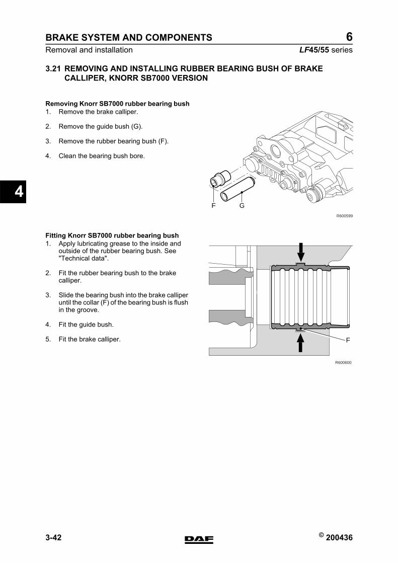
BRAKE SYSTEM AND COMPONENTS
3-42 © 200436
Removal and installation
4
ΛΦ45/55 series6
3.21 REMOVING AND INSTALLING RUBBER BEARING BUSH OF BRAKE CALLIPER, KNORR SB7000 VERSION
Removing Knorr SB7000 rubber bearing bush1. Remove the brake calliper.
2. Remove the guide bush (G).
3. Remove the rubber bearing bush (F).
4. Clean the bearing bush bore.
Fitting Knorr SB7000 rubber bearing bush1. Apply lubricating grease to the inside and
outside of the rubber bearing bush. See "Technical data".
2. Fit the rubber bearing bush to the brake calliper.
3. Slide the bearing bush into the brake calliper until the collar (F) of the bearing bush is flush in the groove.
4. Fit the guide bush.
5. Fit the brake calliper.
GR600599
F
R600600
F
https://www.truck-manuals.net/
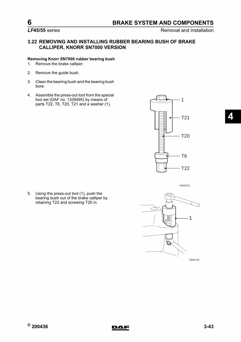
© 200436 3-43
Removal and installationBRAKE SYSTEM AND COMPONENTS
ΛΦ45/55 series6
4
3.22 REMOVING AND INSTALLING RUBBER BEARING BUSH OF BRAKE CALLIPER, KNORR SN7000 VERSION
Removing Knorr SN7000 rubber bearing bush1. Remove the brake calliper.
2. Remove the guide bush.
3. Clean the bearing bush and the bearing bush bore.
4. Assemble the press-out tool from the special tool set (DAF no. 1329495) by means of parts T22, T6, T20, T21 and a washer (1).
5. Using the press-out tool (1), push the bearing bush out of the brake calliper by retaining T22 and screwing T20 in.
R600763
1
T21
T20
T6
T22
1
R600729
https://www.truck-manuals.net/
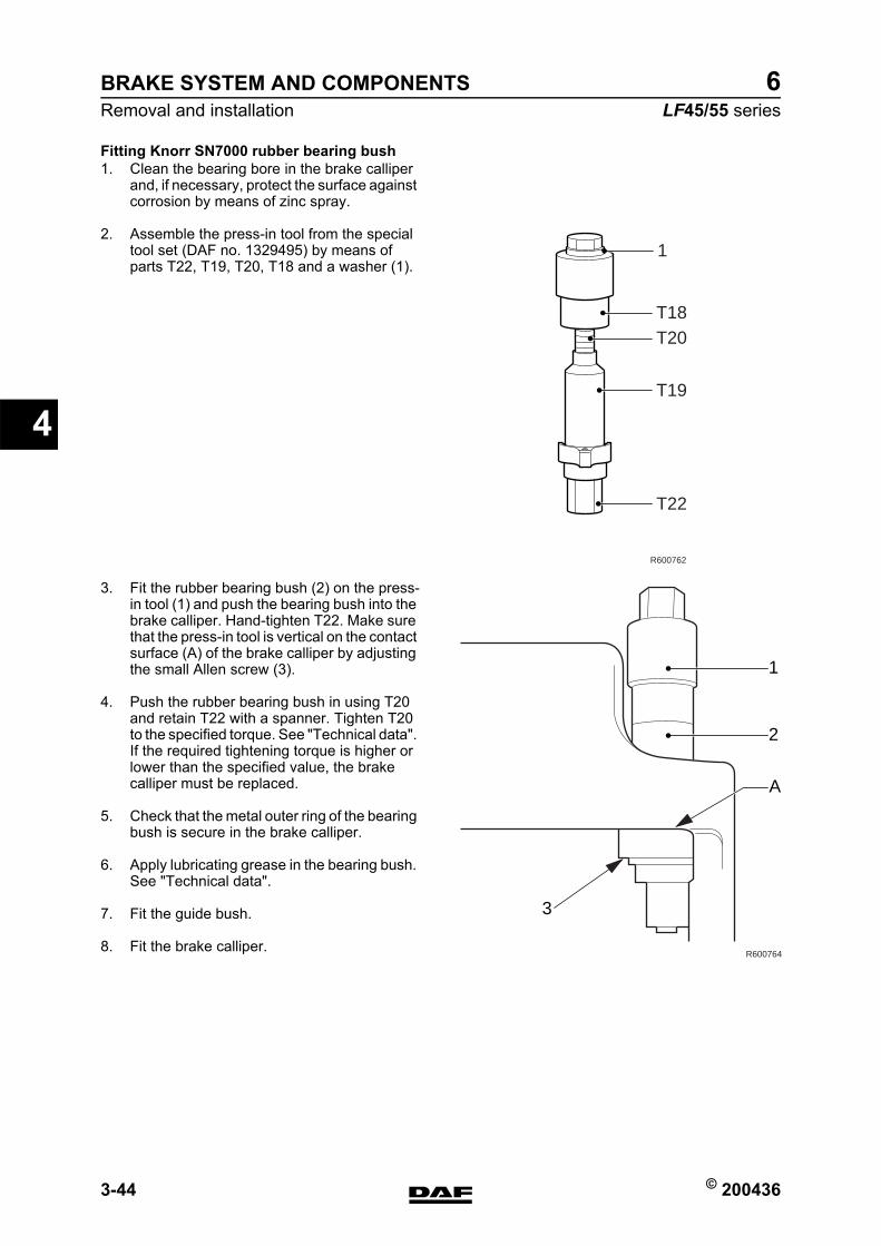
BRAKE SYSTEM AND COMPONENTS
3-44 © 200436
Removal and installation
4
ΛΦ45/55 series6
Fitting Knorr SN7000 rubber bearing bush1. Clean the bearing bore in the brake calliper
and, if necessary, protect the surface against corrosion by means of zinc spray.
2. Assemble the press-in tool from the special tool set (DAF no. 1329495) by means of parts T22, T19, T20, T18 and a washer (1).
3. Fit the rubber bearing bush (2) on the press-in tool (1) and push the bearing bush into the brake calliper. Hand-tighten T22. Make sure that the press-in tool is vertical on the contact surface (A) of the brake calliper by adjusting the small Allen screw (3).
4. Push the rubber bearing bush in using T20 and retain T22 with a spanner. Tighten T20 to the specified torque. See "Technical data". If the required tightening torque is higher or lower than the specified value, the brake calliper must be replaced.
5. Check that the metal outer ring of the bearing bush is secure in the brake calliper.
6. Apply lubricating grease in the bearing bush. See "Technical data".
7. Fit the guide bush.
8. Fit the brake calliper.
R600762
1
T18T20
T19
T22
R600764
A
3
1
2
https://www.truck-manuals.net/
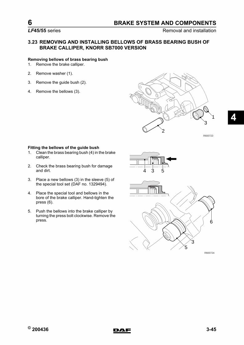
© 200436 3-45
Removal and installationBRAKE SYSTEM AND COMPONENTS
ΛΦ45/55 series6
4
3.23 REMOVING AND INSTALLING BELLOWS OF BRASS BEARING BUSH OF BRAKE CALLIPER, KNORR SB7000 VERSION
Removing bellows of brass bearing bush1. Remove the brake calliper.
2. Remove washer (1).
3. Remove the guide bush (2).
4. Remove the bellows (3).
Fitting the bellows of the guide bush1. Clean the brass bearing bush (4) in the brake
calliper.
2. Check the brass bearing bush for damage and dirt.
3. Place a new bellows (3) in the sleeve (5) of the special tool set (DAF no. 1329494).
4. Place the special tool and bellows in the bore of the brake calliper. Hand-tighten the press (6).
5. Push the bellows into the brake calliper by turning the press bolt clockwise. Remove the press.
2
31
R600723
534
53
6
R600724
https://www.truck-manuals.net/
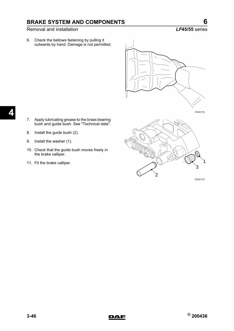
BRAKE SYSTEM AND COMPONENTS
3-46 © 200436
Removal and installation
4
ΛΦ45/55 series6
6. Check the bellows fastening by pulling it outwards by hand. Damage is not permitted.
7. Apply lubricating grease to the brass bearing bush and guide bush. See "Technical data".
8. Install the guide bush (2).
9. Install the washer (1).
10. Check that the guide bush moves freely in the brake calliper.
11. Fit the brake calliper.
R600725
2
31
R600723
https://www.truck-manuals.net/
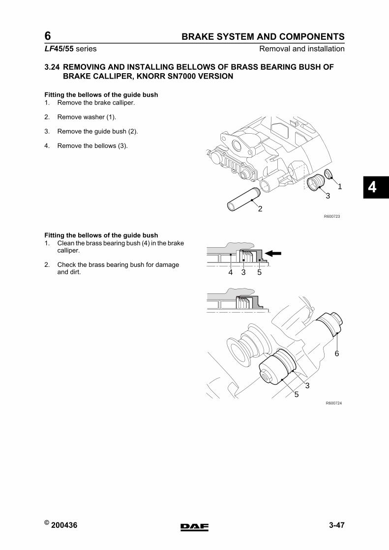
© 200436 3-47
Removal and installationBRAKE SYSTEM AND COMPONENTS
ΛΦ45/55 series6
4
3.24 REMOVING AND INSTALLING BELLOWS OF BRASS BEARING BUSH OF BRAKE CALLIPER, KNORR SN7000 VERSION
Fitting the bellows of the guide bush1. Remove the brake calliper.
2. Remove washer (1).
3. Remove the guide bush (2).
4. Remove the bellows (3).
Fitting the bellows of the guide bush1. Clean the brass bearing bush (4) in the brake
calliper.
2. Check the brass bearing bush for damage and dirt.
2
31
R600723
534
53
6
R600724
https://www.truck-manuals.net/
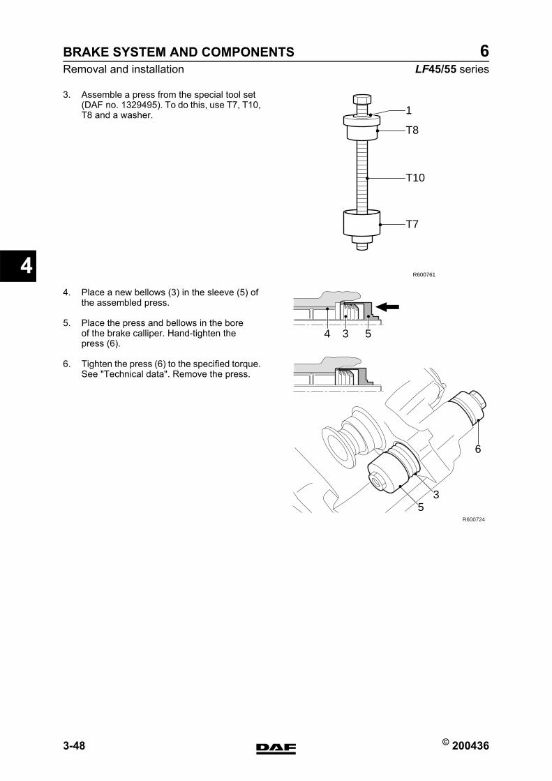
BRAKE SYSTEM AND COMPONENTS
3-48 © 200436
Removal and installation
4
ΛΦ45/55 series6
3. Assemble a press from the special tool set (DAF no. 1329495). To do this, use T7, T10, T8 and a washer.
4. Place a new bellows (3) in the sleeve (5) of the assembled press.
5. Place the press and bellows in the bore of the brake calliper. Hand-tighten the press (6).
6. Tighten the press (6) to the specified torque. See "Technical data". Remove the press.
1
T8
T10
T7
R600761
534
53
6
R600724
https://www.truck-manuals.net/
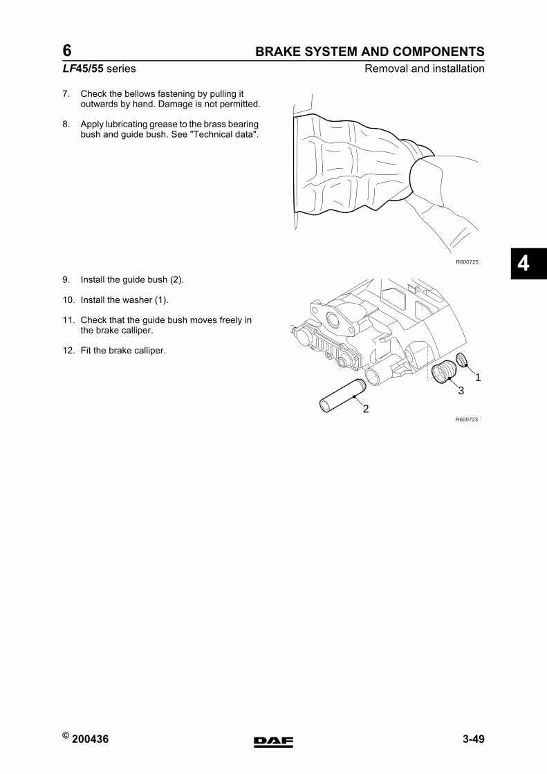
© 200436 3-49
Removal and installationBRAKE SYSTEM AND COMPONENTS
ΛΦ45/55 series6
4
7. Check the bellows fastening by pulling it outwards by hand. Damage is not permitted.
8. Apply lubricating grease to the brass bearing bush and guide bush. See "Technical data".
9. Install the guide bush (2).
10. Install the washer (1).
11. Check that the guide bush moves freely in the brake calliper.
12. Fit the brake calliper.
R600725
2
31
R600723
https://www.truck-manuals.net/
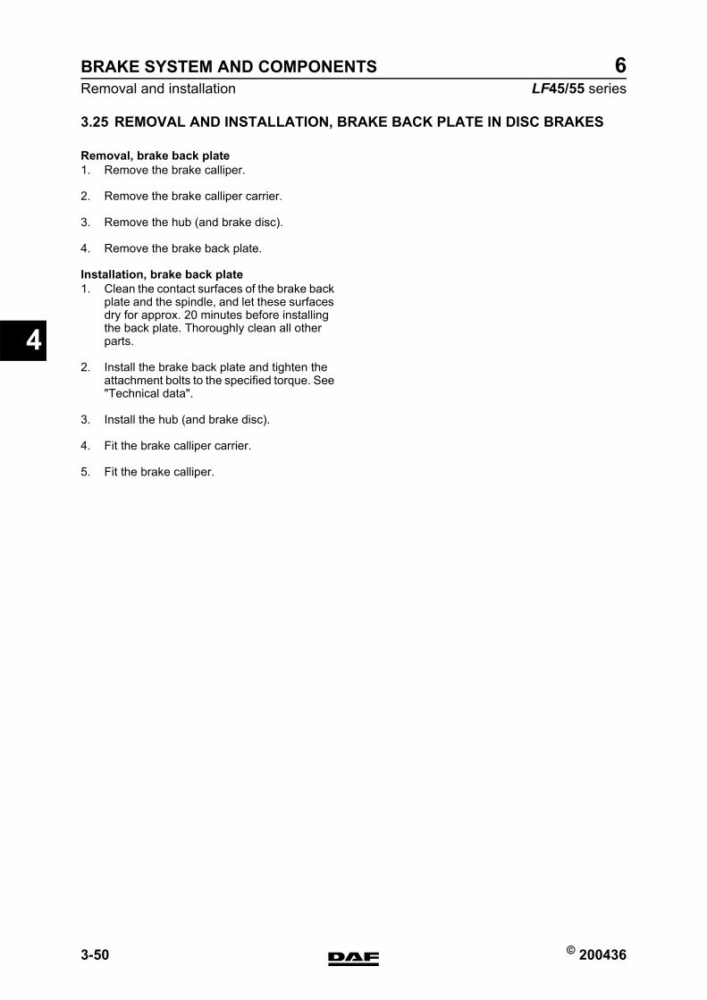
BRAKE SYSTEM AND COMPONENTS
3-50 © 200436
Removal and installation
4
ΛΦ45/55 series6
3.25 REMOVAL AND INSTALLATION, BRAKE BACK PLATE IN DISC BRAKES
Removal, brake back plate1. Remove the brake calliper.
2. Remove the brake calliper carrier.
3. Remove the hub (and brake disc).
4. Remove the brake back plate.
Installation, brake back plate1. Clean the contact surfaces of the brake back
plate and the spindle, and let these surfaces dry for approx. 20 minutes before installing the back plate. Thoroughly clean all other parts.
2. Install the brake back plate and tighten the attachment bolts to the specified torque. See "Technical data".
3. Install the hub (and brake disc).
4. Fit the brake calliper carrier.
5. Fit the brake calliper.
https://www.truck-manuals.net/
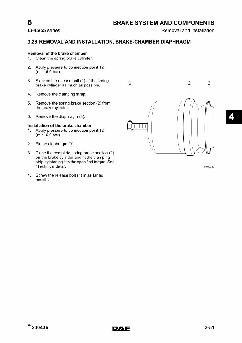
© 200436 3-51
Removal and installationBRAKE SYSTEM AND COMPONENTS
ΛΦ45/55 series6
4
3.26 REMOVAL AND INSTALLATION, BRAKE-CHAMBER DIAPHRAGM
Removal of the brake chamber1. Clean the spring brake cylinder.
2. Apply pressure to connection point 12 (min. 6.0 bar).
3. Slacken the release bolt (1) of the spring brake cylinder as much as possible.
4. Remove the clamping strap.
5. Remove the spring brake section (2) from the brake cylinder.
6. Remove the diaphragm (3).
Installation of the brake chamber1. Apply pressure to connection point 12
(min. 6.0 bar).
2. Fit the diaphragm (3).
3. Place the complete spring brake section (2) on the brake cylinder and fit the clamping strip, tightening it to the specified torque. See "Technical data".
4. Screw the release bolt (1) in as far as possible.
321
R600787
https://www.truck-manuals.net/

BRAKE SYSTEM AND COMPONENTS
3-52 © 200436
Removal and installation
4
ΛΦ45/55 series6
https://www.truck-manuals.net/
© 200436 1
ContentsBRAKING PERFORMANCE AND BRAKE EQUALISATION
ΛΦ45/55 series6
5
5 Braking performance and brake equalisationCONTENTSPage Date
1. GENERAL . . . . . . . . . . . . . . . . . . . . . . . . . . . . . . . . . . . . . . . . . . . . . . . . . . . . . . 1-1 . . . . . 2004361.1 Introduction . . . . . . . . . . . . . . . . . . . . . . . . . . . . . . . . . . . . . . . . . . . . . . . . 1-1 . . . . . 2004361.2 What is a vehicle combination with a good braking performance? . . . . . . 1-2 . . . . . 2004361.3 Brake equalisation measurement by means of brake dynamometer. . . . . 1-4 . . . . . 2004361.4 Brake equalisation form for brake dynamometer. . . . . . . . . . . . . . . . . . . . 1-5 . . . . . 2004361.5 EC band for a laden tractor/semi-trailer combination . . . . . . . . . . . . . . . . 1-8 . . . . . 2004361.6 EC band for a laden truck/trailer combination . . . . . . . . . . . . . . . . . . . . . . 1-9 . . . . . 200436
2. INSPECTION AND ADJUSTMENT. . . . . . . . . . . . . . . . . . . . . . . . . . . . . . . . . . . 2-1 . . . . . 2004362.1 Inspecting and adjusting brake equalisation of non-EBS truck with non-
EBS trailer vehicle . . . . . . . . . . . . . . . . . . . . . . . . . . . . . . . . . . . . . . . . . . . 2-1 . . . . . 2004362.2 Inspecting and adjusting brake equalisation of non-EBS truck with EBS
trailer vehicle . . . . . . . . . . . . . . . . . . . . . . . . . . . . . . . . . . . . . . . . . . . . . . . 2-4 . . . . . 200436
https://www.truck-manuals.net/

BRAKING PERFORMANCE AND BRAKE EQUALISATION
2 © 200436
Contents
5
ΛΦ45/55 series6
https://www.truck-manuals.net/
© 200436 1-1
GeneralBRAKING PERFORMANCE AND BRAKE EQUALISATION
ΛΦ45/55 series6
5
1. GENERAL1.1 INTRODUCTION
How is a good braking performance of a vehicle combination (truck and trailer vehicle) achieved while still guaranteeing interchangeability both for new vehicle combinations and for combinations following brake reconditioning?The vehicles should meet the legal requirements and all settings should be in accordance with the directives. However, adhering to the directives does not necessarily mean that there will be no brake problems.
https://www.truck-manuals.net/
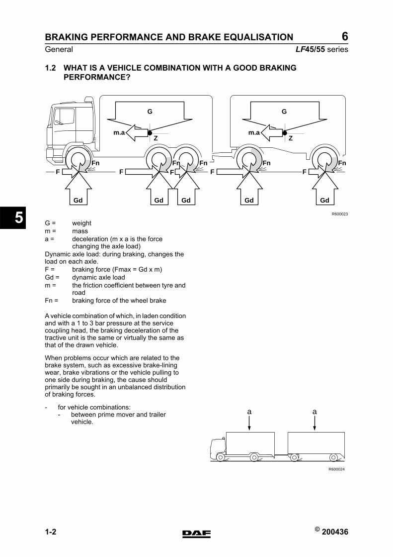
BRAKING PERFORMANCE AND BRAKE EQUALISATION
1-2 © 200436
General
5
ΛΦ45/55 series6
1.2 WHAT IS A VEHICLE COMBINATION WITH A GOOD BRAKING PERFORMANCE?
A vehicle combination of which, in laden condition and with a 1 to 3 bar pressure at the service coupling head, the braking deceleration of the tractive unit is the same or virtually the same as that of the drawn vehicle.
When problems occur which are related to the brake system, such as excessive brake-lining wear, brake vibrations or the vehicle pulling to one side during braking, the cause should primarily be sought in an unbalanced distribution of braking forces.
- for vehicle combinations:- between prime mover and trailer
vehicle.
Fn
Gd
FFn
Gd
F
Zm.a
Fn
Gd
FFn
Gd
FFn
Gd
F
Z
GG
m.a
R600023
G = weightm = massa = deceleration (m x a is the force
changing the axle load)Dynamic axle load: during braking, changes the load on each axle.F = braking force (Fmax = Gd x m)Gd = dynamic axle loadm = the friction coefficient between tyre and
roadFn = braking force of the wheel brake
a
R600024
a
https://www.truck-manuals.net/
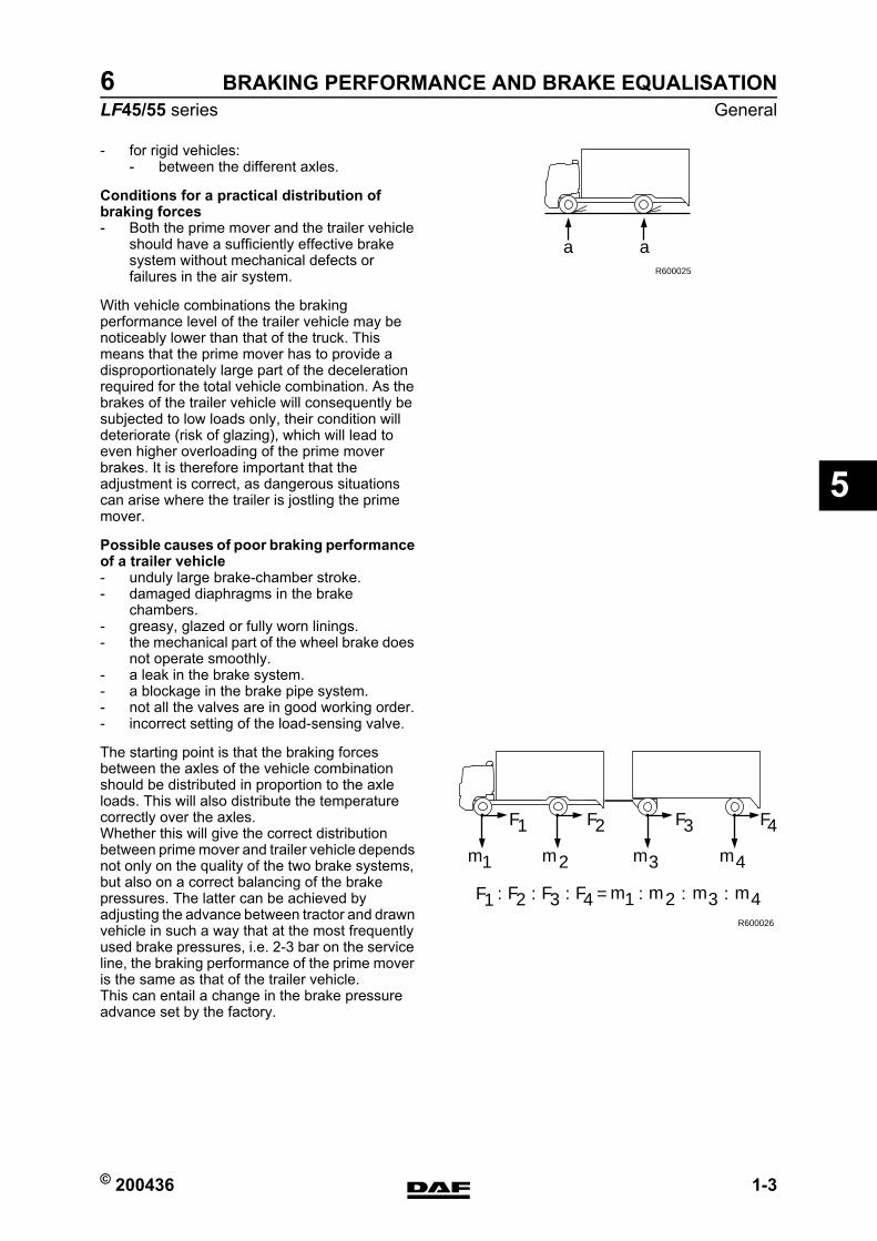
© 200436 1-3
GeneralBRAKING PERFORMANCE AND BRAKE EQUALISATION
ΛΦ45/55 series6
5
- for rigid vehicles:- between the different axles.
Conditions for a practical distribution of braking forces- Both the prime mover and the trailer vehicle
should have a sufficiently effective brake system without mechanical defects or failures in the air system.
With vehicle combinations the braking performance level of the trailer vehicle may be noticeably lower than that of the truck. This means that the prime mover has to provide a disproportionately large part of the deceleration required for the total vehicle combination. As the brakes of the trailer vehicle will consequently be subjected to low loads only, their condition will deteriorate (risk of glazing), which will lead to even higher overloading of the prime mover brakes. It is therefore important that the adjustment is correct, as dangerous situations can arise where the trailer is jostling the prime mover.
Possible causes of poor braking performance of a trailer vehicle- unduly large brake-chamber stroke.- damaged diaphragms in the brake
chambers.- greasy, glazed or fully worn linings.- the mechanical part of the wheel brake does
not operate smoothly.- a leak in the brake system.- a blockage in the brake pipe system.- not all the valves are in good working order.- incorrect setting of the load-sensing valve.
The starting point is that the braking forces between the axles of the vehicle combination should be distributed in proportion to the axle loads. This will also distribute the temperature correctly over the axles.Whether this will give the correct distribution between prime mover and trailer vehicle depends not only on the quality of the two brake systems, but also on a correct balancing of the brake pressures. The latter can be achieved by adjusting the advance between tractor and drawn vehicle in such a way that at the most frequently used brake pressures, i.e. 2-3 bar on the service line, the braking performance of the prime mover is the same as that of the trailer vehicle.This can entail a change in the brake pressure advance set by the factory.
a aR600025
R600026
m1 m3 m4
F1
F :1
F2 F3 F4
F2 F3 4
m2
m1 m3 m4m2: F: = : : :
https://www.truck-manuals.net/
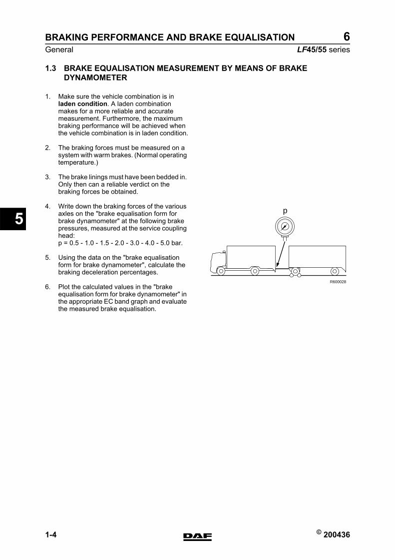
BRAKING PERFORMANCE AND BRAKE EQUALISATION
1-4 © 200436
General
5
ΛΦ45/55 series6
1.3 BRAKE EQUALISATION MEASUREMENT BY MEANS OF BRAKE DYNAMOMETER
1. Make sure the vehicle combination is in laden condition. A laden combination makes for a more reliable and accurate measurement. Furthermore, the maximum braking performance will be achieved when the vehicle combination is in laden condition.
2. The braking forces must be measured on a system with warm brakes. (Normal operating temperature.)
3. The brake linings must have been bedded in. Only then can a reliable verdict on the braking forces be obtained.
4. Write down the braking forces of the various axles on the "brake equalisation form for brake dynamometer" at the following brake pressures, measured at the service coupling head:p = 0.5 - 1.0 - 1.5 - 2.0 - 3.0 - 4.0 - 5.0 bar.
5. Using the data on the "brake equalisation form for brake dynamometer", calculate the braking deceleration percentages.
6. Plot the calculated values in the "brake equalisation form for brake dynamometer" in the appropriate EC band graph and evaluate the measured brake equalisation.
p
R600028
https://www.truck-manuals.net/
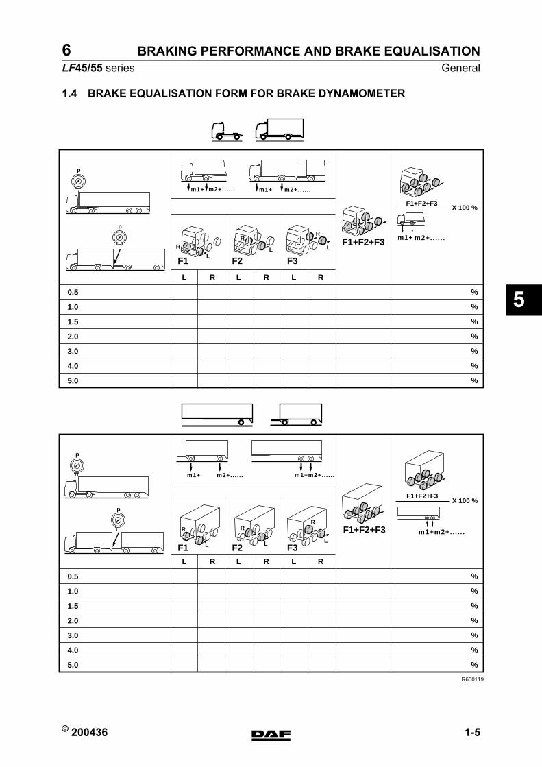
© 200436 1-5
GeneralBRAKING PERFORMANCE AND BRAKE EQUALISATION
ΛΦ45/55 series6
5
1.4 BRAKE EQUALISATION FORM FOR BRAKE DYNAMOMETER
R600119
R LL R L R
0.5
1.0
1.5
2.0
3.0
4.0
5.0
%
%
%
%
%
%
%
R LL R L R
0.5
1.0
1.5
2.0
3.0
4.0
5.0
%
%
%
%
%
%
%
p
p
p
p
m1+ m2+.. . . . . m1+ m2+.. . . . .
m1+m2+.. . . . .m1+ m2+.. . . . .
R
L
R
L
R
L
R
L
R
L
R
L
F1 F2 F3
F1 F2 F3
F1+F2+F3 m1+ m2+.. . . . .
F1+F2+F3X 100 %
F1+F2+F3
X 100 %
m1+m2+.. . . . .
F1+F2+F3
https://www.truck-manuals.net/
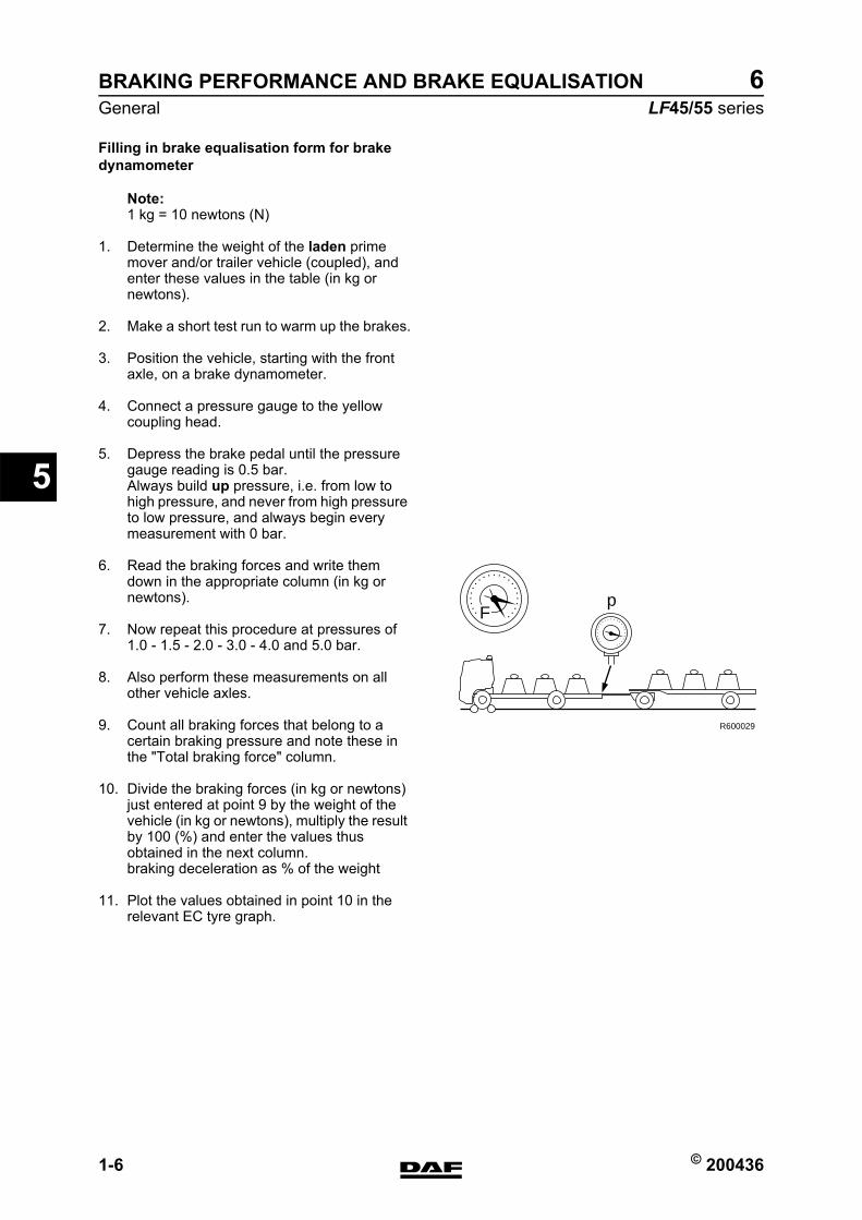
BRAKING PERFORMANCE AND BRAKE EQUALISATION
1-6 © 200436
General
5
ΛΦ45/55 series6
Filling in brake equalisation form for brake dynamometer
Note:1 kg = 10 newtons (N)
1. Determine the weight of the laden prime mover and/or trailer vehicle (coupled), and enter these values in the table (in kg or newtons).
2. Make a short test run to warm up the brakes.
3. Position the vehicle, starting with the front axle, on a brake dynamometer.
4. Connect a pressure gauge to the yellow coupling head.
5. Depress the brake pedal until the pressure gauge reading is 0.5 bar.Always build up pressure, i.e. from low to high pressure, and never from high pressure to low pressure, and always begin every measurement with 0 bar.
6. Read the braking forces and write them down in the appropriate column (in kg or newtons).
7. Now repeat this procedure at pressures of 1.0 - 1.5 - 2.0 - 3.0 - 4.0 and 5.0 bar.
8. Also perform these measurements on all other vehicle axles.
9. Count all braking forces that belong to a certain braking pressure and note these in the "Total braking force" column.
10. Divide the braking forces (in kg or newtons) just entered at point 9 by the weight of the vehicle (in kg or newtons), multiply the result by 100 (%) and enter the values thus obtained in the next column.braking deceleration as % of the weight
11. Plot the values obtained in point 10 in the relevant EC tyre graph.
Fp
R600029
https://www.truck-manuals.net/
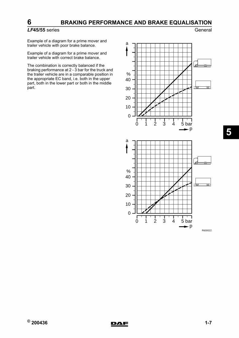
© 200436 1-7
GeneralBRAKING PERFORMANCE AND BRAKE EQUALISATION
ΛΦ45/55 series6
5
Example of a diagram for a prime mover and trailer vehicle with poor brake balance.
Example of a diagram for a prime mover and trailer vehicle with correct brake balance.
The combination is correctly balanced if the braking performance at 2 - 3 bar for the truck and the trailer vehicle are in a comparable position in the appropriate EC band, i.e. both in the upper part, both in the lower part or both in the middle part.
%
a
40
30
20
10
0
10 2 3 4 5 barp
%
a
40
30
20
10
0
10 2 3 4 5 barp
R600022
https://www.truck-manuals.net/
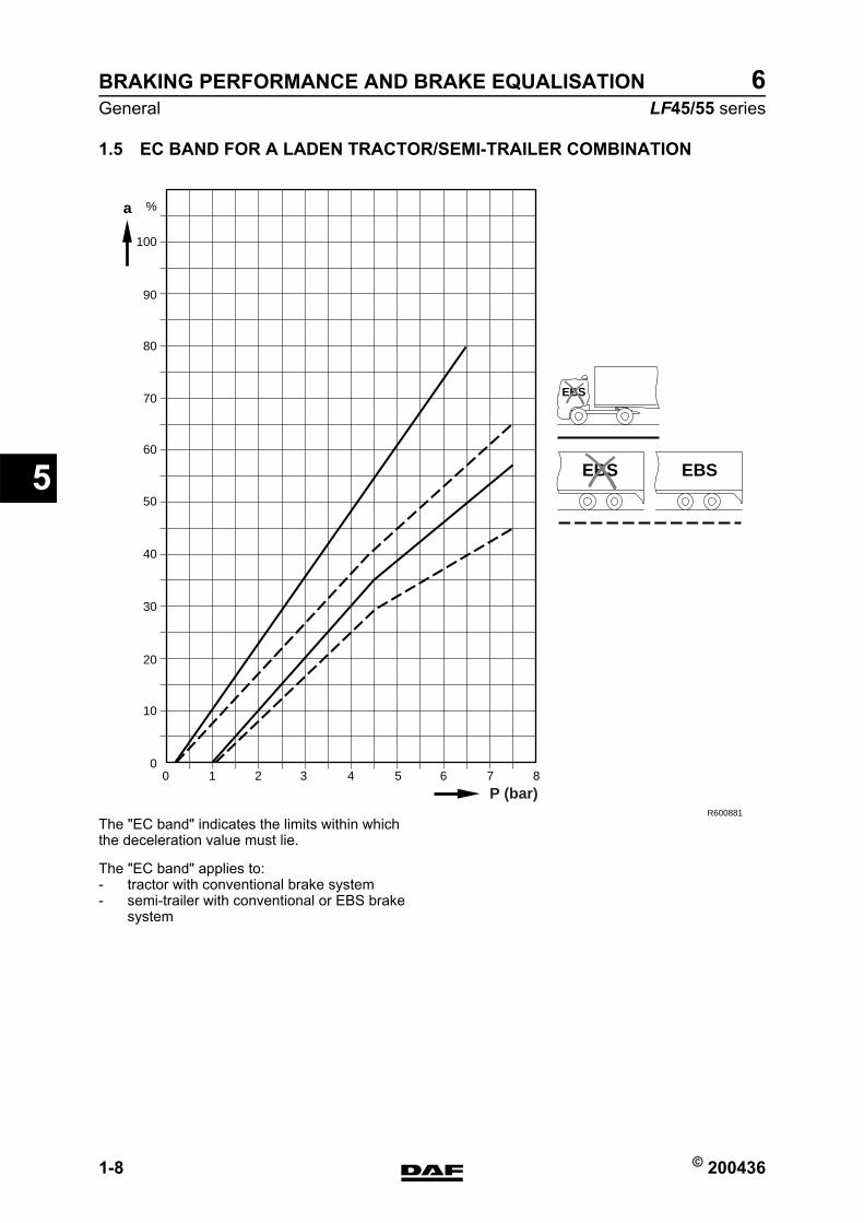
BRAKING PERFORMANCE AND BRAKE EQUALISATION
1-8 © 200436
General
5
ΛΦ45/55 series6
1.5 EC BAND FOR A LADEN TRACTOR/SEMI-TRAILER COMBINATION
The "EC band" indicates the limits within which the deceleration value must lie.
The "EC band" applies to:- tractor with conventional brake system- semi-trailer with conventional or EBS brake
system
100
%a
90
80
70
60
50
40
30
20
10
010 2 3 4 5 6 7 8
R600881
EBS EBS
P (bar)
EBS
https://www.truck-manuals.net/
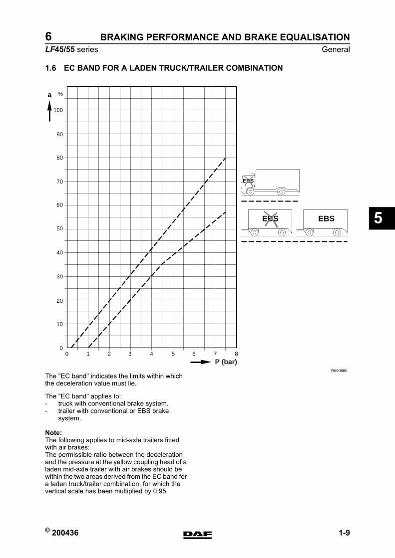
© 200436 1-9
GeneralBRAKING PERFORMANCE AND BRAKE EQUALISATION
ΛΦ45/55 series6
5
1.6 EC BAND FOR A LADEN TRUCK/TRAILER COMBINATION
The "EC band" indicates the limits within which the deceleration value must lie.
The "EC band" applies to:- truck with conventional brake system.- trailer with conventional or EBS brake
system.
Note:The following applies to mid-axle trailers fitted with air brakes:The permissible ratio between the deceleration and the pressure at the yellow coupling head of a laden mid-axle trailer with air brakes should be within the two areas derived from the EC band for a laden truck/trailer combination, for which the vertical scale has been multiplied by 0.95.
100
%
90
80
70
60
50
40
30
20
10
010 2 3 4 5 6 7 8
R600880
P (bar)
EBS EBS
a
EBS
https://www.truck-manuals.net/
BRAKING PERFORMANCE AND BRAKE EQUALISATION
1-10 © 200436
General
5
ΛΦ45/55 series6
https://www.truck-manuals.net/
© 200436 2-1
Inspection and adjustmentBRAKING PERFORMANCE AND BRAKE EQUALISATION
ΛΦ45/55 series6
5
2. INSPECTION AND ADJUSTMENT2.1 INSPECTING AND ADJUSTING BRAKE EQUALISATION OF NON-EBS
TRUCK WITH NON-EBS TRAILER VEHICLE
Inspecting brake equalisation of non-EBS truck with non-EBS trailer vehicle1. Take a test drive and evaluate the braking
behaviour.
2. In the case of disc brakes, inspect the mechanical condition of the brake calliper, brake disc and brake pads. In the case of drum brakes, inspect the mechanical condition of the brake drums and brake linings. Their condition may provide clues to the settings that need to be made.
3. Perform a brake equalisation test using a brake dynamometer and fill in the "Brake equalisation form for brake dynamometer". See "General".
4. Evaluate the brake equalisation of the combination using the "EC band graph". The combination is correctly balanced if the braking performance at 2 - 3 bar for the truck and the trailer vehicle are in a comparable position in the appropriate EC band, i.e. both in the upper part, both in the lower part or both in the middle part.
Note:On a tractor/drawn vehicle combination the values for the drawn vehicle may be slightly lower than those for the prime mover. The deceleration values for the truck and the drawn vehicle of a truck/trailer combination should be the same. The reason for this lies in the dynamic axle load displacement, which on semi-trailers causes a transfer of weight to the tractive unit, whereas on trailers it does not cause a transfer of weight to the tractive unit.
5. Due to the adjustment of the brake pressure advance on the truck and/or trailer vehicle the deceleration lines in the "EC band graph" can be affected.
Note:For optimum interchangeability of vehicles, the correct choice between these two alternatives must be made.
https://www.truck-manuals.net/
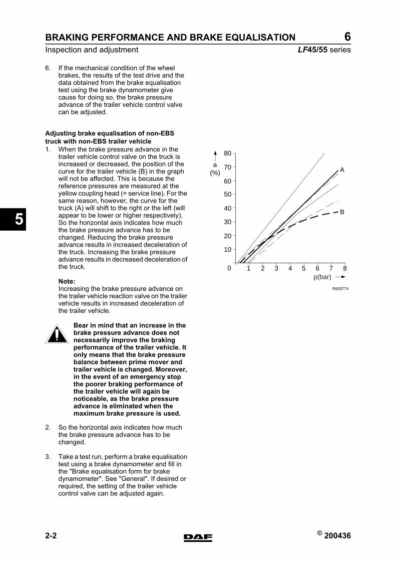
BRAKING PERFORMANCE AND BRAKE EQUALISATION
2-2 © 200436
Inspection and adjustment
5
ΛΦ45/55 series6
6. If the mechanical condition of the wheel brakes, the results of the test drive and the data obtained from the brake equalisation test using the brake dynamometer give cause for doing so, the brake pressure advance of the trailer vehicle control valve can be adjusted.
Adjusting brake equalisation of non-EBS truck with non-EBS trailer vehicle1. When the brake pressure advance in the
trailer vehicle control valve on the truck is increased or decreased, the position of the curve for the trailer vehicle (B) in the graph will not be affected. This is because the reference pressures are measured at the yellow coupling head (= service line). For the same reason, however, the curve for the truck (A) will shift to the right or the left (will appear to be lower or higher respectively).So the horizontal axis indicates how much the brake pressure advance has to be changed. Reducing the brake pressure advance results in increased deceleration of the truck. Increasing the brake pressure advance results in decreased deceleration of the truck.
Note:Increasing the brake pressure advance on the trailer vehicle reaction valve on the trailer vehicle results in increased deceleration of the trailer vehicle.
Bear in mind that an increase in the brake pressure advance does not necessarily improve the braking performance of the trailer vehicle. It only means that the brake pressure balance between prime mover and trailer vehicle is changed. Moreover, in the event of an emergency stop the poorer braking performance of the trailer vehicle will again be noticeable, as the brake pressure advance is eliminated when the maximum brake pressure is used.
2. So the horizontal axis indicates how much the brake pressure advance has to be changed.
3. Take a test run, perform a brake equalisation test using a brake dynamometer and fill in the "Brake equalisation form for brake dynamometer". See "General". If desired or required, the setting of the trailer vehicle control valve can be adjusted again.
R600774
0
10
20
30
40
50
60
70
80
a(%) A
B
1 2 3 4 5 6 7 8p(bar)
}
https://www.truck-manuals.net/
© 200436 2-3
Inspection and adjustmentBRAKING PERFORMANCE AND BRAKE EQUALISATION
ΛΦ45/55 series6
5
4. If the desired brake equalisation cannot be achieved, the cause must be sought and remedied by means of the diagnostics table. See "Diagnostics".
https://www.truck-manuals.net/
BRAKING PERFORMANCE AND BRAKE EQUALISATION
2-4 © 200436
Inspection and adjustment
5
ΛΦ45/55 series6
2.2 INSPECTING AND ADJUSTING BRAKE EQUALISATION OF NON-EBS TRUCK WITH EBS TRAILER VEHICLE
Inspecting brake equalisation of non-EBS truck with EBS trailer vehicle1. Take a test drive and evaluate the braking
behaviour.
2. In the case of disc brakes, inspect the mechanical condition of the brake calliper, brake disc and brake pads. In the case of drum brakes, inspect the mechanical condition of the brake drums and brake linings. Their condition may provide clues to the settings that need to be made.
3. Perform a brake equalisation test using a brake dynamometer and fill in the "Brake equalisation form for brake dynamometer". See "General".
Note:The EBS trailer vehicle must be correctly connected and the test function of the EBS system must be activated.
4. Evaluate the brake equalisation of the combination using the "EC band graph". The combination is correctly balanced if the braking performance at 2 - 3 bar for the truck and the trailer vehicle are in a comparable position in the appropriate EC band, i.e. both in the upper part, both in the lower part or both in the middle part.
Note:On a tractor/semi-trailer combination the values for the drawn vehicle may be slightly lower than those for the tractor. The deceleration values for the truck and the drawn vehicle of a truck/trailer combination should be the same. The reason for this lies in the dynamic axle load displacement, which on semi-trailers causes a transfer of weight to the tractive unit, whereas on trailers it does not cause a transfer of weight to the tractive unit.
5. Due to the adjustment of the brake pressure advance on the truck, the deceleration line in the "EC band graph" can be affected.
6. If the mechanical condition of the wheel brakes, the results of the test drive and the data obtained from the brake equalisation test using the brake dynamometer give cause for doing so, the brake pressure advance of the trailer vehicle control valve can be adjusted.
https://www.truck-manuals.net/
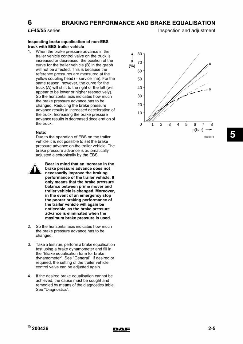
© 200436 2-5
Inspection and adjustmentBRAKING PERFORMANCE AND BRAKE EQUALISATION
ΛΦ45/55 series6
5
Inspecting brake equalisation of non-EBS truck with EBS trailer vehicle1. When the brake pressure advance in the
trailer vehicle control valve on the truck is increased or decreased, the position of the curve for the trailer vehicle (B) in the graph will not be affected. This is because the reference pressures are measured at the yellow coupling head (= service line). For the same reason, however, the curve for the truck (A) will shift to the right or the left (will appear to be lower or higher respectively).So the horizontal axis indicates how much the brake pressure advance has to be changed. Reducing the brake pressure advance results in increased deceleration of the truck. Increasing the brake pressure advance results in decreased deceleration of the truck.
Note:Due to the operation of EBS on the trailer vehicle it is not possible to set the brake pressure advance on the trailer vehicle. The brake pressure advance is automatically adjusted electronically by the EBS.
Bear in mind that an increase in the brake pressure advance does not necessarily improve the braking performance of the trailer vehicle. It only means that the brake pressure balance between prime mover and trailer vehicle is changed. Moreover, in the event of an emergency stop the poorer braking performance of the trailer vehicle will again be noticeable, as the brake pressure advance is eliminated when the maximum brake pressure is used.
2. So the horizontal axis indicates how much the brake pressure advance has to be changed.
3. Take a test run, perform a brake equalisation test using a brake dynamometer and fill in the "Brake equalisation form for brake dynamometer". See "General". If desired or required, the setting of the trailer vehicle control valve can be adjusted again.
4. If the desired brake equalisation cannot be achieved, the cause must be sought and remedied by means of the diagnostics table. See "Diagnostics".
R600774
0
10
20
30
40
50
60
70
80
a(%) A
B
1 2 3 4 5 6 7 8p(bar)
}
https://www.truck-manuals.net/
BRAKING PERFORMANCE AND BRAKE EQUALISATION
2-6 © 200436
Inspection and adjustment
5
ΛΦ45/55 series6
https://www.truck-manuals.net/