©2012 Doble Engineering Company. All Rights Reserved Synchrophasor: Implementation,Testing &...
25
©2012 Doble Engineering Company. All Rights Reserved Synchrophasor: Implementation,Testing & Operational Experience Doble Engineering Company Uttam Mishra
-
Upload
hilary-tyler -
Category
Documents
-
view
220 -
download
1
Transcript of ©2012 Doble Engineering Company. All Rights Reserved Synchrophasor: Implementation,Testing &...
©2012 Doble Engineering Company. All Rights Reserved
Synchrophasor: Implementation,Testing & Operational Experience
Doble Engineering Company
Uttam Mishra
Presentation Topics
What is SynchroPhasor
Applications
Testing PMUs
Operational Experience
Conclusion
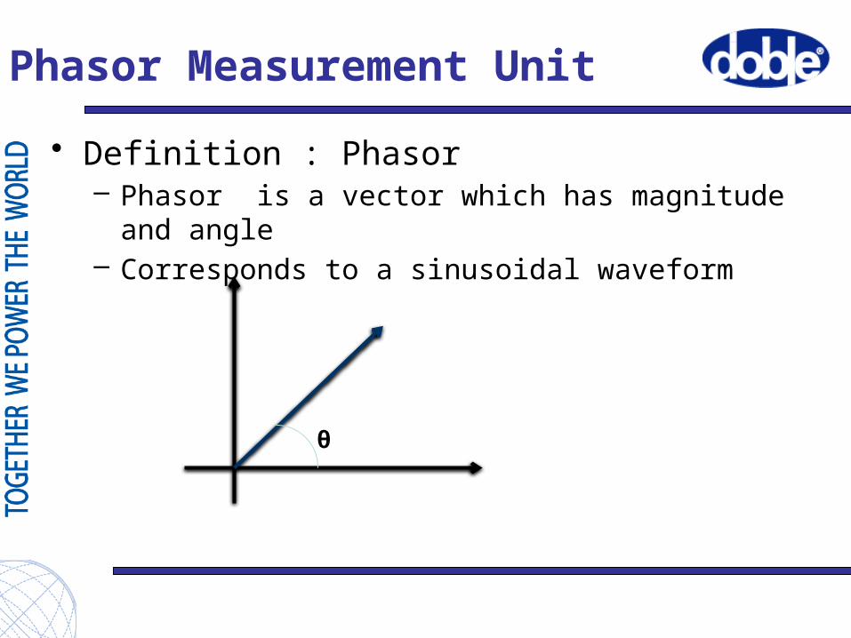
Phasor Measurement Unit
• Definition : Phasor– Phasor is a vector which has magnitude and angle – Corresponds to a sinusoidal waveform
θ
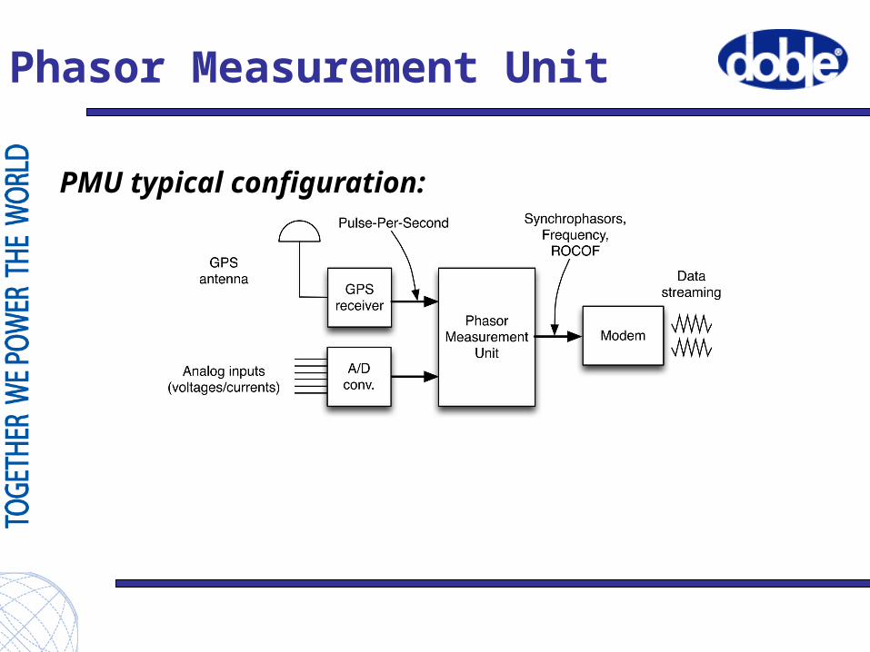
Phasor Measurement Unit
PMU typical configuration:
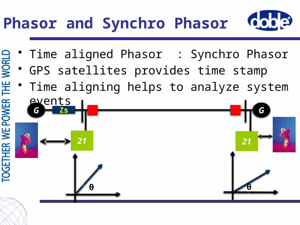
Phasor and Synchro Phasor
• Time aligned Phasor : Synchro Phasor• GPS satellites provides time stamp• Time aligning helps to analyze system events
G GZs
21 21
θ θ
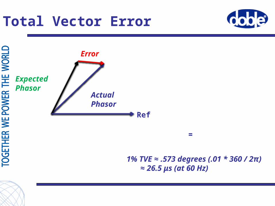
Total Vector Error
=
Actual Phasor
Expected Phasor
Error
Ref
1% TVE ≈ .573 degrees (.01 * 360 / 2π)≈ 26.5 μs (at 60 Hz)
Back up applications
• Power system stability• Two ended fault location algorithm• System diagnostics• Distributed Busbar protection• Load shedding• Wide area frequency monitoring
Power Swing Detection
• Protections settings done with known max and/or min operating conditions of power system events
• Actual operation of power system events may not be optimal for the setting of the protection
• PMU provides Phasors in real time• Better decision can be made on load shedding
and system stability• Real time Phasor value helps to fine tune State
estimation
8
PMU : Power Swing
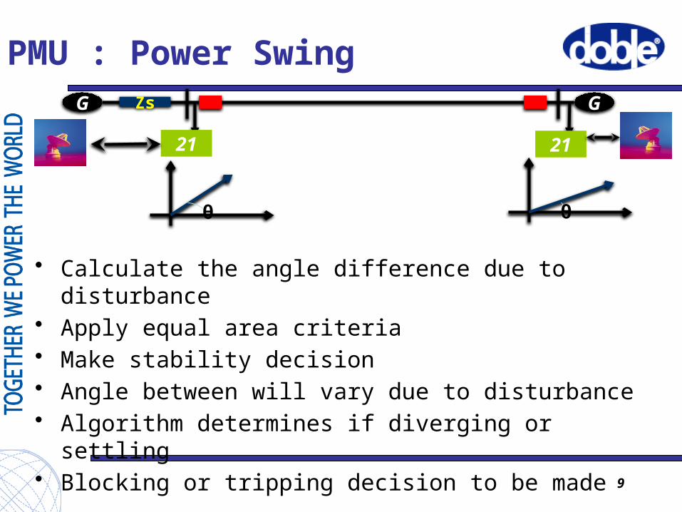
• Calculate the angle difference due to disturbance• Apply equal area criteria• Make stability decision • Angle between will vary due to disturbance• Algorithm determines if diverging or settling• Blocking or tripping decision to be made
9
G GZs
21 21
θ θ
Distance to Fault
• Single ended fault location algorithm inaccuracy– Fault resistance, load flow & non homogenous system
• PMU enables double ended fault location• PMU data from both end of the line provides very
accurate fault location– Reclose decision can be made for mixed overhead and
cable transmission line– Improved line patrolling :Better productivity & Reliability – Fault location algorithm is based on positive sequence
system parameters
10
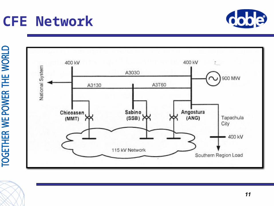
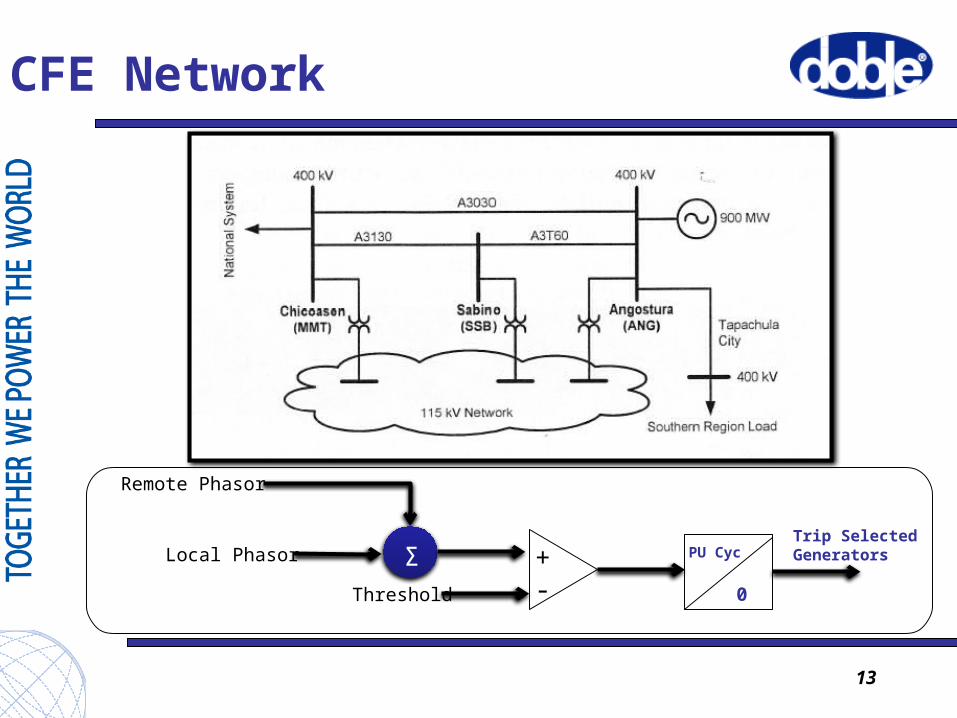
CFE Network
11
Automatic Generation Shedding
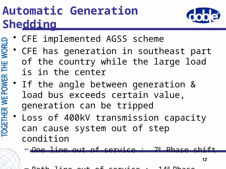
• CFE implemented AGSS scheme• CFE has generation in southeast part of the
country while the large load is in the center• If the angle between generation & load bus
exceeds certain value, generation can be tripped• Loss of 400kV transmission capacity can cause
system out of step condition– One line out of service : 70 Phase shift – Both line out of service : 140 Phase shift
• CFE chose 100 to be setting for load shedding
12
CFE Network
13
Local Phasor
Remote Phasor
ƩThreshold
+-
PU Cyc
0
Trip SelectedGenerators
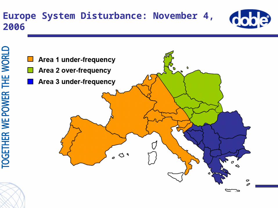
Europe System Disturbance: November 4, 2006
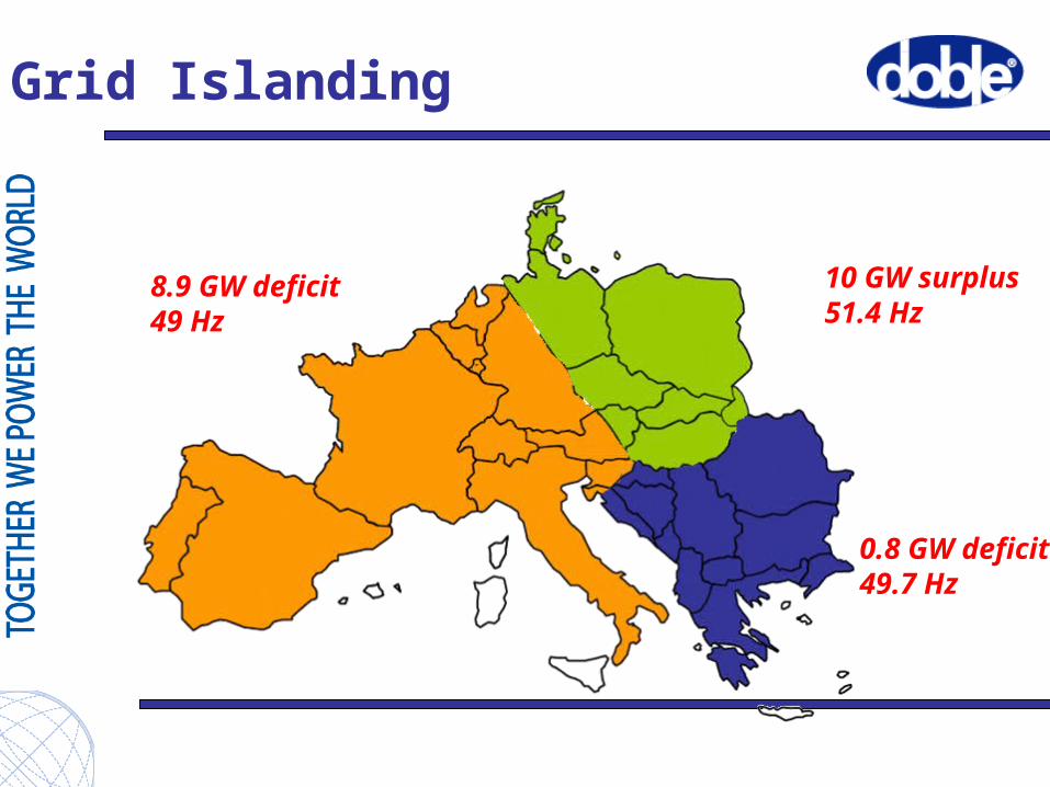
Grid Islanding
10 GW surplus51.4 Hz
0.8 GW deficit49.7 Hz
8.9 GW deficit49 Hz
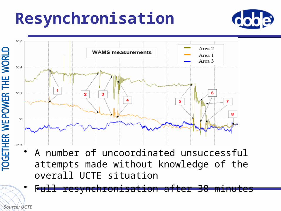
Resynchronisation
• A number of uncoordinated unsuccessful attempts made without knowledge of the overall UCTE situation
• Full resynchronisation after 38 minutes
Source: UCTE
UCTE root cause analysis
• Main points:
– (N-1) security rule, inadequate inter-TSO coordination
– Lack of situational awareness
– Other factors (wind farms, lack of coordination)
Improvements since 2006:
Situational awareness• Web-based visibility of cross-border flows in
Europe, • RAAS – real-time awareness and alarming
system
Coordinated (N-1) security analysis• All national files are merged into one common CE
load flow file. • each TSO downloads the complete system and
perform complete (n-1) calculation.
PMU Testing Concepts
Goal: under various conditions, make sure that the reported each PMU data message matches the expected values for each Phasor Vector, Frequency Deviation and ROCOF.
PMU Testing Standard
• Defined in IEEE C37.118.1• Specifies quantities to vary, ranges to vary over,
and required accuracies under different conditions.
• Includes steady state tests, dynamic tests, and transient tests
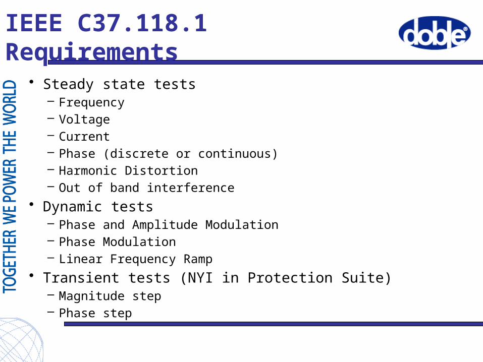
IEEE C37.118.1 Requirements
• Steady state tests– Frequency– Voltage– Current– Phase (discrete or continuous)– Harmonic Distortion– Out of band interference
• Dynamic tests– Phase and Amplitude Modulation– Phase Modulation– Linear Frequency Ramp
• Transient tests (NYI in Protection Suite)– Magnitude step– Phase step
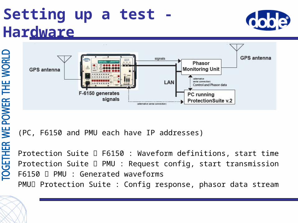
Setting up a test - Hardware
(PC, F6150 and PMU each have IP addresses)
Protection Suite F6150 : Waveform definitions, start timeProtection Suite PMU : Request config, start transmissionF6150 PMU : Generated waveformsPMU Protection Suite : Config response, phasor data stream
Summary
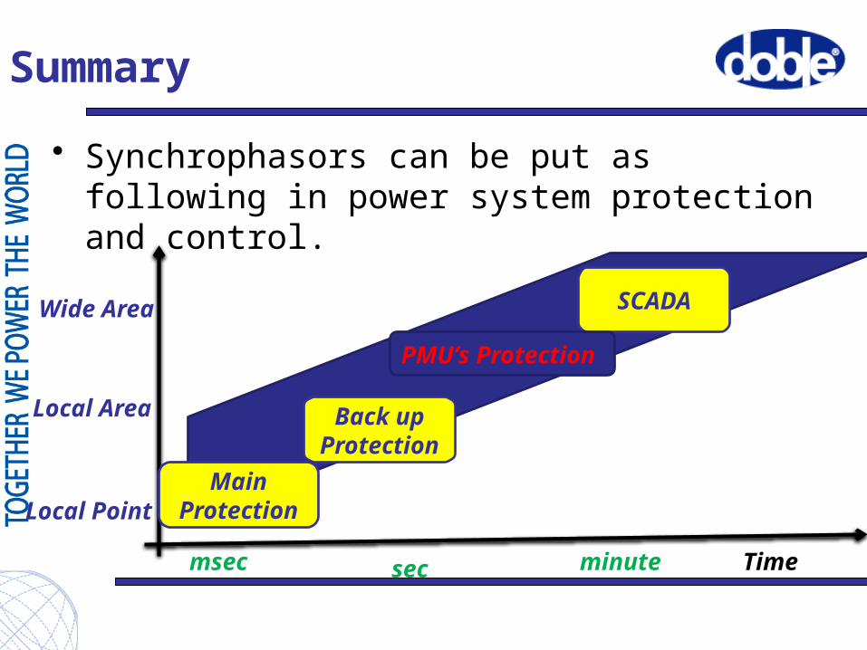
• Synchrophasors can be put as following in power system protection and control.
Main Protection
Back up Protection
SCADA
PMU’s Protection
msec sec minute Time
Wide Area
Local Area
Local Point
Summary
• PMUs and WAMS enable a new dimension of monitoring power grid operation.
• Synchrophasors solve the problem of time incoherency required for wide-area power system control.
• situational awareness and alarming system will help to avoid unwanted disturbance
24