Yun Chung 1 Materials Performance
26
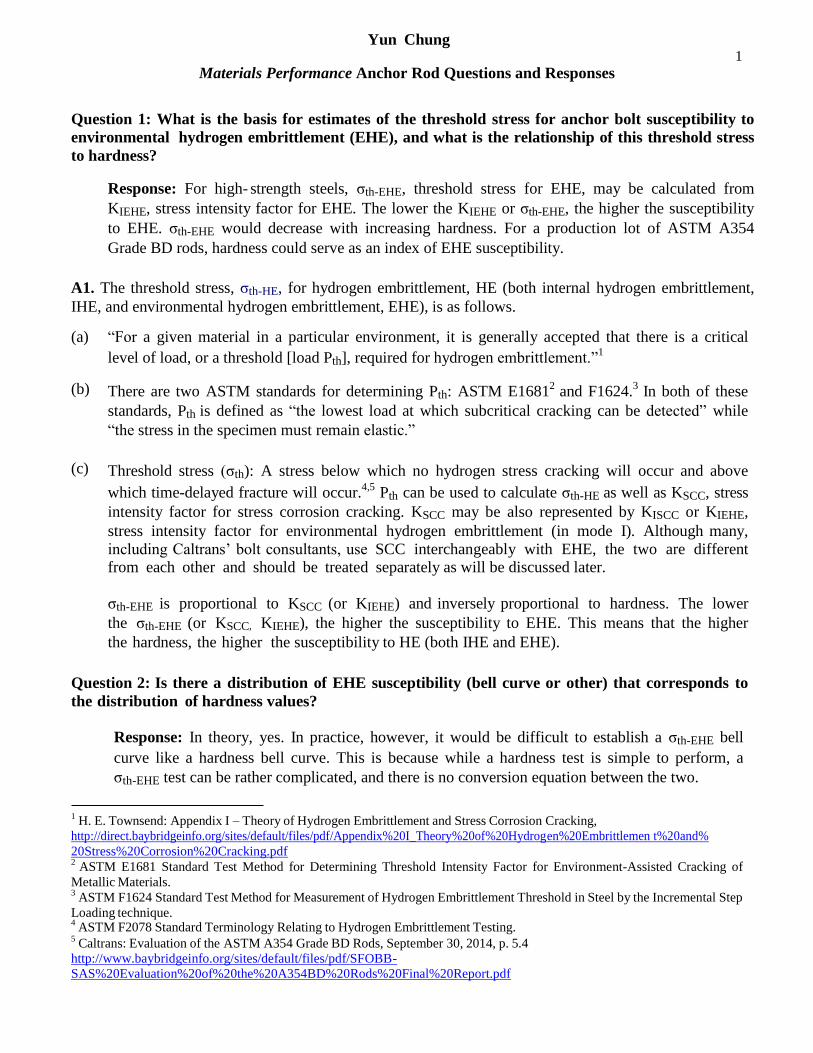
1 Yun Chung Materials Performance Anchor Rod Questions and Responses Question 1: What is the basis for estimates of the threshold stress for anchor bolt susceptibility to environmental hydrogen embrittlement (EHE), and what is the relationship of this threshold stress to hardness? Response: For high- strength steels, σ th-EHE , threshold stress for EHE, may be calculated from K IEHE , stress intensity factor for EHE. The lower the K IEHE or σ th-EHE , the higher the susceptibility to EHE. σ th-EHE would decrease with increasing hardness. For a production lot of ASTM A354 Grade BD rods, hardness could serve as an index of EHE susceptibility. A1. The threshold stress, σ th-HE , for hydrogen embrittlement, HE (both internal hydrogen embrittlement, IHE, and environmental hydrogen embrittlement, EHE), is as follows. (a) “For a given material in a particular environment, it is generally accepted that there is a critical level of load, or a threshold [load P th ], required for hydrogen embrittlement.” 1 (b) There are two ASTM standards for determining P th : ASTM E1681 2 and F1624. 3 In both of these standards, P th is defined as “the lowest load at which subcritical cracking can be detected” while “the stress in the specimen must remain elastic.” (c) Threshold stress (σ th ): A stress below which no hydrogen stress cracking will occur and above which time-delayed fracture will occur. 4,5 P th can be used to calculate σ th-HE as well as K SCC , stress intensity factor for stress corrosion cracking. K SCC may be also represented by K ISCC or K IEHE , stress intensity factor for environmental hydrogen embrittlement (in mode I). Although many, including Caltrans’ bolt consultants, use SCC interchangeably with EHE, the two are different from each other and should be treated separately as will be discussed later. σ th-EHE is proportional to K SCC (or K IEHE ) and inversely proportional to hardness. The lower the σ th-EHE (or K SCC, K IEHE ), the higher the susceptibility to EHE. This means that the higher the hardness, the higher the susceptibility to HE (both IHE and EHE). Question 2: Is there a distribution of EHE susceptibility (bell curve or other) that corresponds to the distribution of hardness values? Response: In theory, yes. In practice, however, it would be difficult to establish a σ th-EHE bell curve like a hardness bell curve. This is because while a hardness test is simple to perform, a σ th-EHE test can be rather complicated, and there is no conversion equation between the two. 1 H. E. Townsend: Appendix I – Theory of Hydrogen Embrittlement and Stress Corrosion Cracking, http://direct.baybridgeinfo.org/sites/default/files/pdf/Appendix%20I_Theory%20of%20Hydrogen%20Embrittlemen t%20and% 20Stress%20Corrosion%20Cracking.pdf 2 ASTM E1681 Standard Test Method for Determining Threshold Intensity Factor for Environment-Assisted Cracking of Metallic Materials. 3 ASTM F1624 Standard Test Method for Measurement of Hydrogen Embrittlement Threshold in Steel by the Incremental Step Loading technique. 4 ASTM F2078 Standard Terminology Relating to Hydrogen Embrittlement Testing. 5 Caltrans: Evaluation of the ASTM A354 Grade BD Rods, September 30, 2014, p. 5.4 http://www.baybridgeinfo.org/sites/default/files/pdf/SFOBB- SAS%20Evaluation%20of%20the%20A354BD%20Rods%20Final%20Report.pdf
Transcript of Yun Chung 1 Materials Performance
1 Yun Chung
Materials Performance Anchor Rod Questions and Responses
Question 1: What is the basis for estimates of the threshold stress for anchor bolt susceptibility to
environmental hydrogen embrittlement (EHE), and what is the relationship of this threshold stress
to hardness?
Response: For high- strength steels, σth-EHE, threshold stress for EHE, may be calculated from
KIEHE, stress intensity factor for EHE. The lower the KIEHE or σth-EHE, the higher the susceptibility
to EHE. σth-EHE would decrease with increasing hardness. For a production lot of ASTM A354
Grade BD rods, hardness could serve as an index of EHE susceptibility.
A1. The threshold stress, σth-HE, for hydrogen embrittlement, HE (both internal hydrogen embrittlement,
IHE, and environmental hydrogen embrittlement, EHE), is as follows.
(a) “For a given material in a particular environment, it is generally accepted that there is a critical
level of load, or a threshold [load Pth], required for hydrogen embrittlement.”1
(b) There are two ASTM standards for determining Pth: ASTM E16812
and F1624.3
In both of these
standards, Pth is defined as “the lowest load at which subcritical cracking can be detected” while
“the stress in the specimen must remain elastic.”
(c) Threshold stress (σth): A stress below which no hydrogen stress cracking will occur and above
which time-delayed fracture will occur.4,5
Pth can be used to calculate σth-HE as well as KSCC, stress
intensity factor for stress corrosion cracking. KSCC may be also represented by KISCC or KIEHE,
stress intensity factor for environmental hydrogen embrittlement (in mode I). Although many,
including Caltrans’ bolt consultants, use SCC interchangeably with EHE, the two are different from each other and should be treated separately as will be discussed later.
σth-EHE is proportional to KSCC (or KIEHE) and inversely proportional to hardness. The lower
the σth-EHE (or KSCC, KIEHE), the higher the susceptibility to EHE. This means that the higher
the hardness, the higher the susceptibility to HE (both IHE and EHE).
Question 2: Is there a distribution of EHE susceptibility (bell curve or other) that corresponds to
the distribution of hardness values?
Response: In theory, yes. In practice, however, it would be difficult to establish a σth-EHE bell
curve like a hardness bell curve. This is because while a hardness test is simple to perform, a
σth-EHE test can be rather complicated, and there is no conversion equation between the two.
1 H. E. Townsend: Appendix I – Theory of Hydrogen Embrittlement and Stress Corrosion Cracking,
http://direct.baybridgeinfo.org/sites/default/files/pdf/Appendix%20I_Theory%20of%20Hydrogen%20Embrittlemen t%20and%
20Stress%20Corrosion%20Cracking.pdf 2
ASTM E1681 Standard Test Method for Determining Threshold Intensity Factor for Environment-Assisted Cracking of
Metallic Materials. 3
ASTM F1624 Standard Test Method for Measurement of Hydrogen Embrittlement Threshold in Steel by the Incremental Step
Loading technique. 4
ASTM F2078 Standard Terminology Relating to Hydrogen Embrittlement Testing. 5
Caltrans: Evaluation of the ASTM A354 Grade BD Rods, September 30, 2014, p. 5.4
http://www.baybridgeinfo.org/sites/default/files/pdf/SFOBB-
SAS%20Evaluation%20of%20the%20A354BD%20Rods%20Final%20Report.pdf
2 Yun Chung
For example, Caltrans claimed to have determined 0.65Fu and 0.75Fu as σth-EHE for the “2008 BD
rods” and “2010 BD rods,” respectively, from Test IV, Townsend (Stress Corrosion Cracking)
Test.6
The 0.65Fu cannot be σth-EHE, however, for the entire “2008 BD rods” because not all of
them failed subsequent to pretensioning to 0.70Fu. The 0.75Fu cannot be σth-EHE for the “2010 BD
rods” because it was determined from only one rod with 36 - 37 HRC. The 0.75Fu cannot
represent the “2010 BD rods” with hardness higher than 37 HRC. Therefore, Caltrans was wrong
to state that the “2010 BD rods” now in service are safe from EHE failures because they have been
pretensioned to 0.70Fu. Caltrans picked the specimens for Test IV without regards to their
hardness, and the test protocols did not conform to the test protocols for threshold load (Pth-EHE)
determination, for example in ASTM E1681 and F1624. Thus, the σth-EHE data Caltrans produced
are mostly questionable.
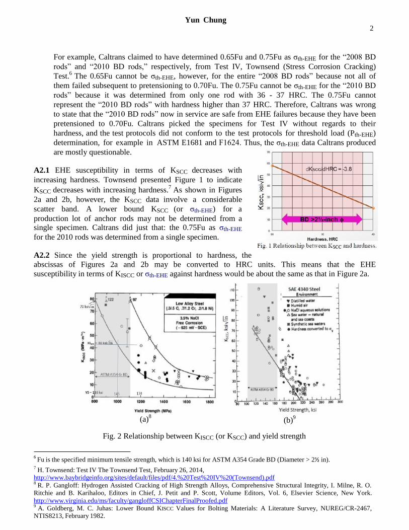
A2.1 EHE susceptibility in terms of KSCC decreases with
increasing hardness. Townsend presented Figure 1 to indicate
KSCC decreases with increasing hardness.7
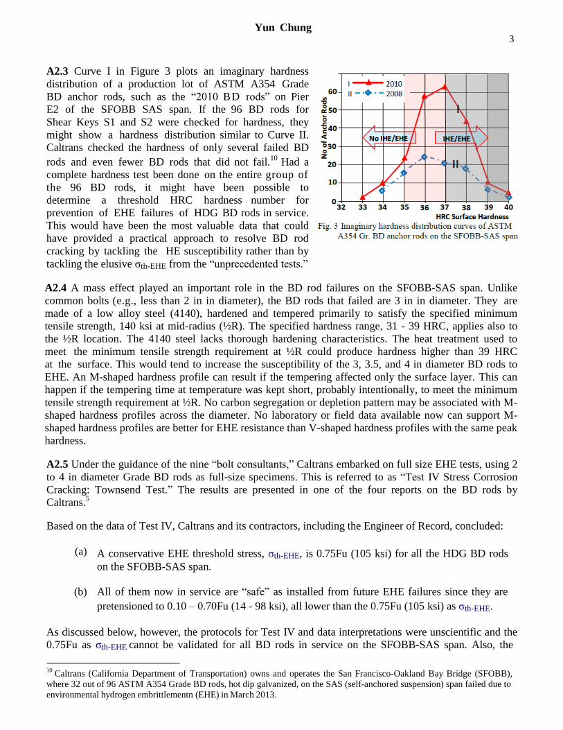
As shown in Figures
2a and 2b, however, the KSCC data involve a considerable
scatter band. A lower bound KSCC (or σth-EHE) for a
production lot of anchor rods may not be determined from a single specimen. Caltrans did just that: the 0.75Fu as σth-EHE
for the 2010 rods was determined from a single specimen.
A2.2 Since the yield strength is proportional to hardness, the
abscissas of Figures 2a and 2b may be converted to HRC units. This means that the EHE
susceptibility in terms of KISCC or σth-EHE against hardness would be about the same as that in Figure 2a.
Fig. 2 Relationship between KISCC (or KSCC) and yield strength
6 Fu is the specified minimum tensile strength, which is 140 ksi for ASTM A354 Grade BD (Diameter > 2½ in).
7 H. Townsend: Test IV The Townsend Test, February 26, 2014,
http://www.baybridgeinfo.org/sites/default/files/pdf/4.%20Test%20IV%20(Townsend).pdf 8
R. P. Gangloff: Hydrogen Assisted Cracking of High Strength Alloys, Comprehensive Structural Integrity, I. Milne, R. O.
Ritchie and B. Karihaloo, Editors in Chief, J. Petit and P. Scott, Volume Editors, Vol. 6, Elsevier Science, New York.
http://www.virginia.edu/ms/faculty/gangloffCSIChapterFinalProofed.pdf 9
A. Goldberg, M. C. Juhas: Lower Bound KISCC Values for Bolting Materials: A Literature Survey, NUREG/CR-2467, NTIS8213, February 1982.
(a)8 (b)
9
3 Yun Chung
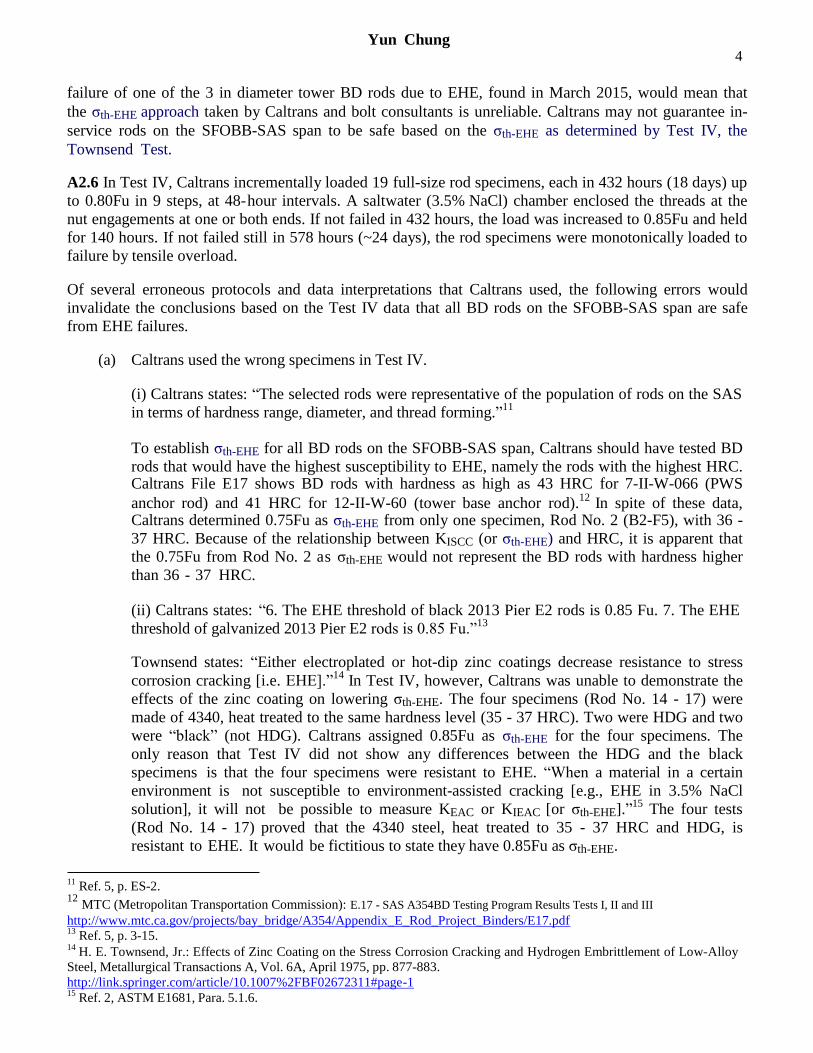
A2.3 Curve I in Figure 3 plots an imaginary hardness
distribution of a production lot of ASTM A354 Grade
BD anchor rods, such as the “2010 BD rods” on Pier
E2 of the SFOBB SAS span. If the 96 BD rods for
Shear Keys S1 and S2 were checked for hardness, they
might show a hardness distribution similar to Curve II.
Caltrans checked the hardness of only several failed BD
rods and even fewer BD rods that did not fail.10
Had a
complete hardness test been done on the entire group of
the 96 BD rods, it might have been possible to
determine a threshold HRC hardness number for
prevention of EHE failures of HDG BD rods in service.
This would have been the most valuable data that could
have provided a practical approach to resolve BD rod
cracking by tackling the HE susceptibility rather than by
tackling the elusive σth-EHE from the “unprecedented tests.”
A2.4 A mass effect played an important role in the BD rod failures on the SFOBB-SAS span. Unlike
common bolts (e.g., less than 2 in in diameter), the BD rods that failed are 3 in in diameter. They are
made of a low alloy steel (4140), hardened and tempered primarily to satisfy the specified minimum
tensile strength, 140 ksi at mid-radius (½R). The specified hardness range, 31 - 39 HRC, applies also to
the ½R location. The 4140 steel lacks thorough hardening characteristics. The heat treatment used to
meet the minimum tensile strength requirement at ½R could produce hardness higher than 39 HRC
at the surface. This would tend to increase the susceptibility of the 3, 3.5, and 4 in diameter BD rods to
EHE. An M-shaped hardness profile can result if the tempering affected only the surface layer. This can
happen if the tempering time at temperature was kept short, probably intentionally, to meet the minimum
tensile strength requirement at ½R. No carbon segregation or depletion pattern may be associated with M-
shaped hardness profiles across the diameter. No laboratory or field data available now can support M-
shaped hardness profiles are better for EHE resistance than V-shaped hardness profiles with the same peak
hardness.
A2.5 Under the guidance of the nine “bolt consultants,” Caltrans embarked on full size EHE tests, using 2
to 4 in diameter Grade BD rods as full-size specimens. This is referred to as “Test IV Stress Corrosion
Cracking: Townsend Test.” The results are presented in one of the four reports on the BD rods by
Caltrans.5
Based on the data of Test IV, Caltrans and its contractors, including the Engineer of Record, concluded:
(a) A conservative EHE threshold stress, σth-EHE, is 0.75Fu (105 ksi) for all the HDG BD rods
on the SFOBB-SAS span.
(b) All of them now in service are “safe” as installed from future EHE failures since they are
pretensioned to 0.10 – 0.70Fu (14 - 98 ksi), all lower than the 0.75Fu (105 ksi) as σth-EHE.
As discussed below, however, the protocols for Test IV and data interpretations were unscientific and the
0.75Fu as σth-EHE cannot be validated for all BD rods in service on the SFOBB-SAS span. Also, the
10 Caltrans (California Department of Transportation) owns and operates the San Francisco-Oakland Bay Bridge (SFOBB),
where 32 out of 96 ASTM A354 Grade BD rods, hot dip galvanized, on the SAS (self-anchored suspension) span failed due to
environmental hydrogen embrittlementn (EHE) in March 2013.
4 Yun Chung
failure of one of the 3 in diameter tower BD rods due to EHE, found in March 2015, would mean that
the σth-EHE approach taken by Caltrans and bolt consultants is unreliable. Caltrans may not guarantee in-
service rods on the SFOBB-SAS span to be safe based on the σth-EHE as determined by Test IV, the
Townsend Test.
A2.6 In Test IV, Caltrans incrementally loaded 19 full-size rod specimens, each in 432 hours (18 days) up
to 0.80Fu in 9 steps, at 48-hour intervals. A saltwater (3.5% NaCl) chamber enclosed the threads at the
nut engagements at one or both ends. If not failed in 432 hours, the load was increased to 0.85Fu and held
for 140 hours. If not failed still in 578 hours (~24 days), the rod specimens were monotonically loaded to
failure by tensile overload.
Of several erroneous protocols and data interpretations that Caltrans used, the following errors would
invalidate the conclusions based on the Test IV data that all BD rods on the SFOBB-SAS span are safe
from EHE failures.
(a) Caltrans used the wrong specimens in Test IV.
(i) Caltrans states: “The selected rods were representative of the population of rods on the SAS
in terms of hardness range, diameter, and thread forming.”11
To establish σth-EHE for all BD rods on the SFOBB-SAS span, Caltrans should have tested BD
rods that would have the highest susceptibility to EHE, namely the rods with the highest HRC. Caltrans File E17 shows BD rods with hardness as high as 43 HRC for 7-II-W-066 (PWS
anchor rod) and 41 HRC for 12-II-W-60 (tower base anchor rod).12
In spite of these data, Caltrans determined 0.75Fu as σth-EHE from only one specimen, Rod No. 2 (B2-F5), with 36 -
37 HRC. Because of the relationship between KISCC (or σth-EHE) and HRC, it is apparent that
the 0.75Fu from Rod No. 2 as σth-EHE would not represent the BD rods with hardness higher
than 36 - 37 HRC.
(ii) Caltrans states: “6. The EHE threshold of black 2013 Pier E2 rods is 0.85 Fu. 7. The EHE
threshold of galvanized 2013 Pier E2 rods is 0.85 Fu.”13
Townsend states: “Either electroplated or hot-dip zinc coatings decrease resistance to stress
corrosion cracking [i.e. EHE].”14
In Test IV, however, Caltrans was unable to demonstrate the
effects of the zinc coating on lowering σth-EHE. The four specimens (Rod No. 14 - 17) were
made of 4340, heat treated to the same hardness level (35 - 37 HRC). Two were HDG and two
were “black” (not HDG). Caltrans assigned 0.85Fu as σth-EHE for the four specimens. The
only reason that Test IV did not show any differences between the HDG and the black
specimens is that the four specimens were resistant to EHE. “When a material in a certain
environment is not susceptible to environment-assisted cracking [e.g., EHE in 3.5% NaCl
solution], it will not be possible to measure KEAC or KIEAC [or σth-EHE].”15
The four tests
(Rod No. 14 - 17) proved that the 4340 steel, heat treated to 35 - 37 HRC and HDG, is
resistant to EHE. It would be fictitious to state they have 0.85Fu as σth-EHE.
11 Ref. 5, p. ES-2.
12 MTC (Metropolitan Transportation Commission): E.17 - SAS A354BD Testing Program Results Tests I, II and III
http://www.mtc.ca.gov/projects/bay_bridge/A354/Appendix_E_Rod_Project_Binders/E17.pdf 13
Ref. 5, p. 3-15. 14
H. E. Townsend, Jr.: Effects of Zinc Coating on the Stress Corrosion Cracking and Hydrogen Embrittlement of Low-Alloy
Steel, Metallurgical Transactions A, Vol. 6A, April 1975, pp. 877-883.
http://link.springer.com/article/10.1007%2FBF02672311#page-1 15
Ref. 2, ASTM E1681, Para. 5.1.6.
5 Yun Chung
For the same reason, the rest of the 8 specimens to which Caltrans assigned 0.85Fu as σth-EHE
were simply resistant to EHE in the Test IV environment. The test procedures for these 12 specimens (that had no intergranular cracking (IGC) or subcritical crack growth (SCG) during the loading cycle) were not capable of determining σth-EHE. Caltrans should have
classified them as “no test.”
(b) Caltrans used the wrong test protocols for determining σth-EHE.
Caltrans states: “By convention, EHE thresholds are defined as the last load sustained without
evidence of crack initiation.” 16
Also, “[Note] 6. In accordance with normal practice (e.g.,
ASTM E1681), the threshold values given in Table 3.1-3 represent the last load step at which
cracking was not detected.”17
ASTM E1681 states: “stress intensity factor threshold – the highest value of the stress intensity
factor (K) at which crack growth is not observed …” This presumes that the specimen “meets
the size requirement for linear elastic behavior.”18
ASTM F1624 is more specific: “The
minimum or invariant value of the stress intensity (KISCC, KIIHE, or KIEHE) or stress [σth-EHE or
σth-IHE] for a given geometry with regard to the loading rate, is the threshold for the onset of
crack growth due to hydrogen embrittlement.”19
Also, ASTM F1624 states: “by measuring the threshold for the onset of subcritical crack growth [SCG] …”
20 These requirements preclude
any crack initiation during the final tensile overload failure as a criterion for determining σth
because it occurs in the plastic range and does not involve SCG in an elastic range due to hydrogen embrittlement.
Caltrans applied the criterion of Note 6, above, to the determination of σth-EHE for 17
rod specimens and of σth-IHE for 2 rod specimens. Out of the 19 specimens tested, only 7
showed IGC or SCG and 12 did not. For the 12 specimens without SCG, Caltrans arbitrarily
assigned 0.85Fu as σth-EHE or σth-IHE because 0.85Fu was “the last load step at which cracking
was not detected.” This is invalid, however, because the next load step was the final tensile
overload failure in the plastic range. It is also possible that 0.85Fu is close to or exceeds
the yield strength of the BD rod specimens, thus invalidating the elastic range requirement.
Caltrans defined σth-HE as follows: “Threshold stress (σth): A stress, below which no hydrogen stress cracking will occur and
above which time-delayed fracture will occur.”21
The 12 specimens that had no IGC or SCG cannot have a σth-IHE or σth-EHE because they do not
conform to the above definition. That is, above 0.85Fu, no time-delayed fractures occurred.
Therefore, 0.85Fu cannot be either σth-IHE or σth-EHE.
Caltrans should have treated the 12 specimens without SCG as “no tests” rather than as valid
tests for determining σth-IHE or σth-EHE.
16 Ref. 5, p. 3-11.
17 ibid, p. 3-10.
18 Ref. 2, ASTM E1681, Para. 4.1.1.
19 Ref. 3, ASTM F1624, Para. 4.4.
20 ibid, ASTM F1624, Para. 1.1.
21 Ref. 5, p. 5.4.
6 Yun Chung
(c) Caltrans does not correctly apply the meaning of threshold.
Caltrans states: “The EHE threshold of the 2008 Pier E2 rods is 0.65Fu.”22
This cannot be true. If this were true, all of the 96 HDG BD rods for S1 and S2 should have
failed because they were pretensioned to 0.70Fu. In reality, only 32 failed and 64 did not fail.
Caltrans might think that the 64 BD rods did not fail because they were detensioned to 0.40Fu.
Conversely, the 64 rods did not fail because they were not susceptible to EHE. Caltrans does
not know the hardness distribution of the 64 HDG BD rods that did not fail. If 0.65Fu as the
EHE threshold stress were true, the remaining 64 HDG BD rods for S1 and S2 should have
failed regardless of their CVN toughness values or hardness. In fact, Caltrans’ CVN data on
four unfailed rods from S1 and S2 had nothing remarkably different from those that did fail.
(d) Caltrans misunderstands the difference between IHE and EHE.
Caltrans states: “2. The EHE threshold of the 2008 Pier E2 rods is 0.65 Fu” and “8. The IHE
threshold of 2008 rods is 0.85 Fu.”13
According to ASTM F2078, “The only difference between IHE and EHE is the sequence of applying the stress and exposure to hydrogen” and “Phenomenon is the same! Mechanism is
the same!”23
Then, the threshold stress for IHE should be the same as that for EHE for a given BD rod. It should not vary from 0.65Fu to 0.85Fu, a 30% increase, depending on the test environments, for two specimens of comparable hardness (37 HRC vs 36.5 HRC). This would indicate that Caltrans and bolt consultants devised and conducted Test IV without fully understanding the HE phenomena.
Question 3: What is the safety factor for the hardest anchor bolts?
Response: A safety factor for the BD rods on the SFOBB-SAS span may not be determined. This is
because the σth-EHE data from Test IV are invalid. The safety factor for the “the hardest anchor
bolts” could be less than one, which is unacceptable.
Caltrans (and its bolt consultants) tried to establish σth-EHE by subjecting one or two full- size rod
specimens to step loading cycles in salt-water solution. They also tried to use data from small
specimen (CVN specimen size) tests, called Test V or the Raymond Test, to justify the data of full size specimens of Test IV or the Townsend Test. Philosophically, this scheme is backward. Small specimen data are not used to verify full size specimen data. There are always some problems in extending small specimen data to a full- size rod because of variations in mechanical and other
metallurgical properties across the rod diameter. Either way, it would be difficult to establish σth-EHE
that can guarantee, with a reasonable safety factor (such as 1.3), that all BD rods on the SFOBB-SAS span are safe from EHE failures.
There is another reason why Test V may not be used to validate Test IV. There are no ASTM
test methods for determining σth-EHE directly from a specimen, small or large. σth-EHE may be
22 Ref. 5, p. 3-15.
23 Ref. 4, ASTM F2078, Table X1.1.
7 Yun Chung
calculated only indirectly from KISCC, KIIHE, or KIEHE as determined by Test V, using fracture
mechanics specimens, usually with a fatigue precrack. The fracture mechanics equation for
converting KISCC, KIIHE, or KIEHE to σth-EHE involves a shape factor, which cannot be precise for
a given crack geometry. Thus, the σth-EHE values as determined indirectly from Test V have a
built-in error. They are not exactly equal to those determined by Test IV.
A better approach to avoid EHE failures is to use BD rods that are not susceptible to EHE. This can
be done by limiting the hardness across the rod diameter, for example, to 36 HRC for BD rods with
zinc coating. This will guarantee that the only failure mode for the BD rods is tensile overloading.
A3.1 The anchor rods on the SFOBB-SAS span are pretensioned to 0.1 - 0.7Fu. So, ostensibly, the safety
factor for EHE failures is 0.75Fu/0.70Fu or 1.07 as a minimum.
As discussed above, however, the 0.75Fu as σth-EHE is invalid, particularly for the anchor rods with
hardness greater than 37 HRC. Therefore, the safety factor for the anchor rods on the SFOBB-SAS span may not be determined. For some BD rods, it is likely to be less than 1.0, which is unacceptable.
All engineering measurements involve a probable error. As illustrated in Figures 2a and 2b, the KISCC (or
σth-EHE) data involve a large scatter band (a large probable error). ASTM F1681 requires: “The threshold
load, Pth, is obtained on completion of a minimum of three tests. The threshold is the lowest value of two
consecutive tests, when …”24
The Townsend Test using full size rods as specimens without a (fatigue)
precrack is expected to produce more scatter in data than those from specimens with precracks. A single
test data such as 0.75Fu from one rod specimen is insufficient to assign a minimum EHE threshold stress,
σth-EHE, especially based on an unprecedented “research program” that had no previous validation. There
is no assurance that the 0.75Fu obtained from one specimen (Rod No. 2) is the minimum value. One data
point does not allow a probable error determination. Therefore, Caltrans’ claim of 0.75Fu as σth-EHE for
all BD rods on the SFOBB-SAS span is invalid. It can never qualify as “a conservative threshold.”
A3.2 Even if 0.75Fu is valid as σth-EHE, a safety factor of 1.07 (= 0.75/0.70) is too small to be acceptable. Brian Maroney, Caltrans Chief Engineer for the SFOBB project, stated as follows regarding a 10%
margin during a press conference.25
“… Engineers: We are the practical people. Engineering: It’s never to 5% ... If an engineer tells me
they know anything to within 10%, they are lying to me, or they don’t know what they’re talking
about. Things are not within 10%. …”
Dr. Maroney does not believe a 10% margin as anything that could provide a safe “cushion” to prevent failures due to uncontrollable or unknown factors. His statement reflects the uncertainties in engineering measurements and assumptions used in calculations. The Engineer of Record for the SFOBB-SAS project applied “a safety load factor of 1.4 … to the design based on input from the Seismic Safety Peer Review
Panel (SSPRP).”26,27 “The tie down at the west pier was designed with a factor of safety of two.”
28
24 Ref. 3 ASTM F1624, Para. A1.8.1.
25 Caltrans: Bay Bridge Press Conference 5/20/2015 https://www.youtube.com/watch?v=JNp0L5dzCgU
26 TBPOC: Supplemental Report on the A354 Grade BD High- Strength Steel Rods on the New East Span of the San
Francisco-Oakland Bay Bridge With Findings and Decisions, December 30, 2014, p.18.
http://baybridgeinfo.org/sites/default/files/pdf/Supplemental_Bolt_Report_final.pdf 27
Ref. 5, p.1-4. 28
M. Nader and B. Maroney: One-of-a-Kind Design, The New San Francisco-Oakland Bay Bridge Self-Anchored
Suspension Span, Structure Magazine, October 2007, http://www.structuremag.org/wp-content/uploads/2014/09/F-SFOB-
NaderMaroney- Oct071.pdf
8 Yun Chung
Obviously, the 1.07 safety factor would be unacceptable to most design and construction codes (such as
ASME Section VIII and B31.3), to Dr. Maroney, and to most engineers’ judgments.29
A3.3 TBPOC states: “The margin between the threshold load for cracking, 0.75 Fu, and the applied load
of 0.68 Fu is 0.07 Fu. However, the actual margin between the applied load and the load that could cause
HE is much larger than 0.07 Fu. This is because … with these protective actions [i.e., grease caps, paint,
grout, dehumidification], failure of the rods should not occur until loads of 1.1 Fu or more are reached,
providing a margin of 0.4 Fu between applied loads and failure loads.”26
Caltrans and TBPOC have essentially claimed that the BD rods have a safety factor of 1.6 (= 1.1/0.68).
This cannot be true because this claim is based on flawed reasoning. To state that “failure of the rods
should not occur until loads of 1.1 Fu or more are reached,” the BD rods must be completely immune to
EHE and they can fail only due to tensile overload. This claim was proven wrong when Caltrans
announced one of the tower base BD rods had failed in March - May 2015.
A.3.4 Actually, Caltrans does not know exactly when this rod, 155-1-1 (also referred to as Rod 3), failed.
It was found to be 6 in shorter than it should be during an ultrasonic length measurement in March 2015.
Caltrans pulled it out in May 2015 and found that it had failed at the bottom end of the bottom nut, with
the eleven stripped threads above it.
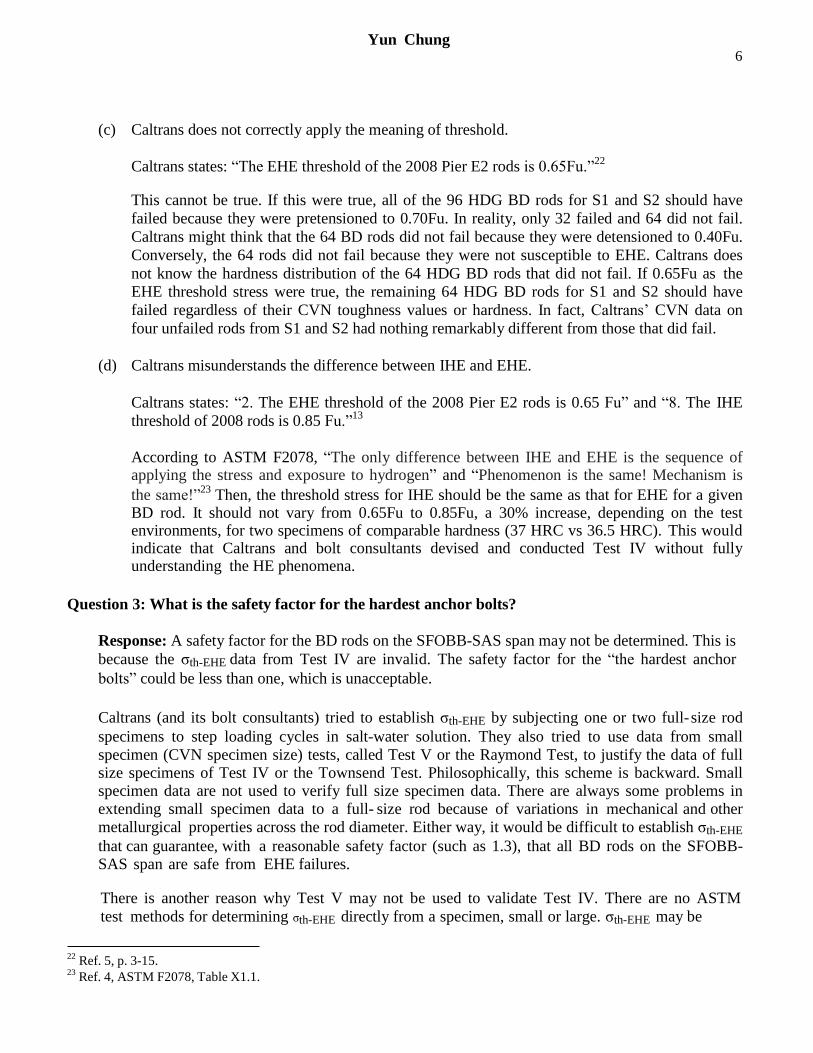
Figure 4a shows the fracture face of this rod.30
It shows that Rod 155-1-1 failed in a macroscopically
brittle manner with the fracture face perpendicular to the rod axis. Only two failure mechanisms can
account for this type of failure at room temperature: fatigue cracking and EHE. Since the tower base
anchor rods are not subjected to cyclic stresses higher than the pretension levels (0.48Fu in this
case), EHE is the only plausible failure mechanism to account for this brittle failure, irrespective of the
fracture mode, intergranular cracking (IGC) vs cleavage.
29 ASME (American Society for Mechanical Engineers) Boiler and Pressure Vessel Code (BPVC) Section VIII, Rules for
Construction of Pressure Vessels. ASME B31.3 Process Piping Guide. 30
TBPOC: Meeting Materials, Sept. 24, 2015 http://baybridgeinfo.org/sites/default/files/pdf/FinalTBPOCPacket-
24Sep15%201_0_1.pdf
9 Yun Chung
The fracture face in Figure 4a displays numerous crack initiation sites. Arrows 1 and 2 point to two of
them. Arrows 3, 4, and 5 in Figure 4b point to three of the numerous ratchet marks. They are the ridges
formed between neighboring fracture propagation zones, each with a separate crack initiation site. The
ratchet marks typically occur in high cycle fatigue cracking, EHE cracking, and SCC.
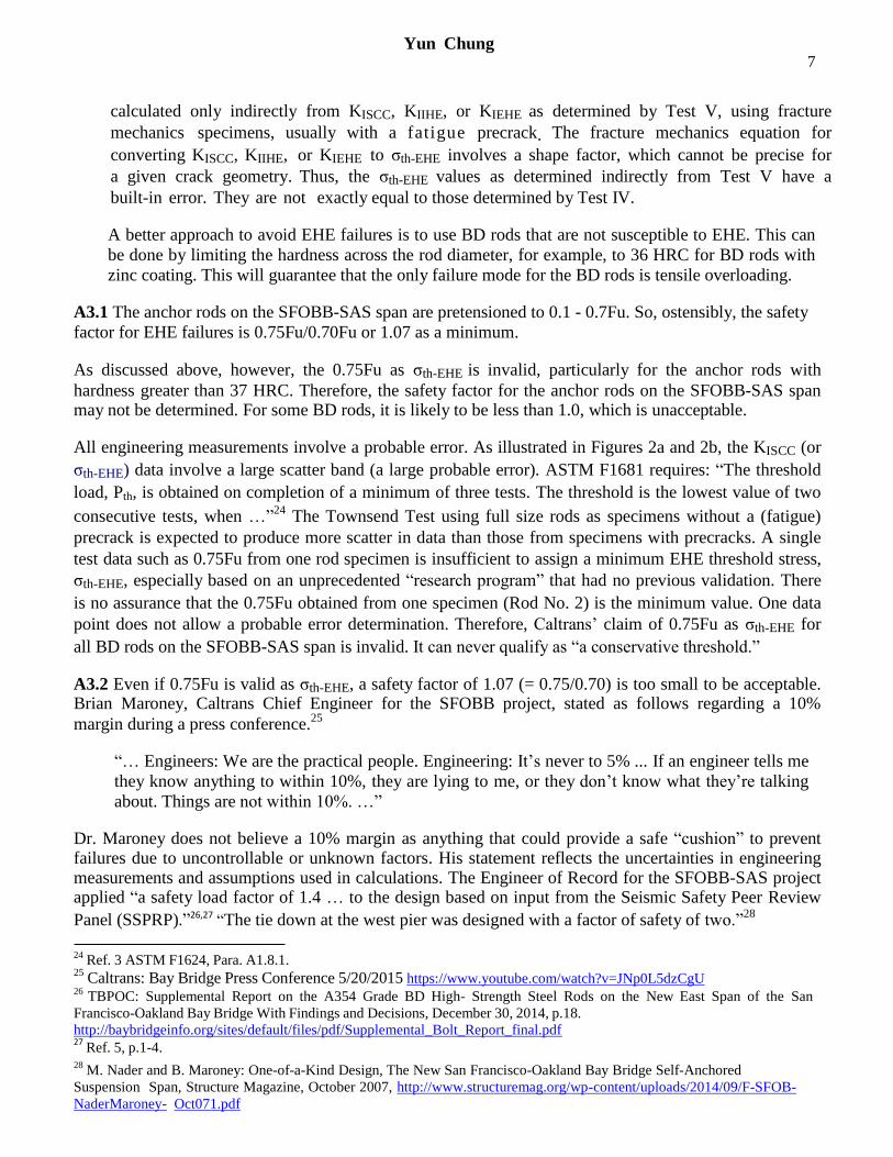
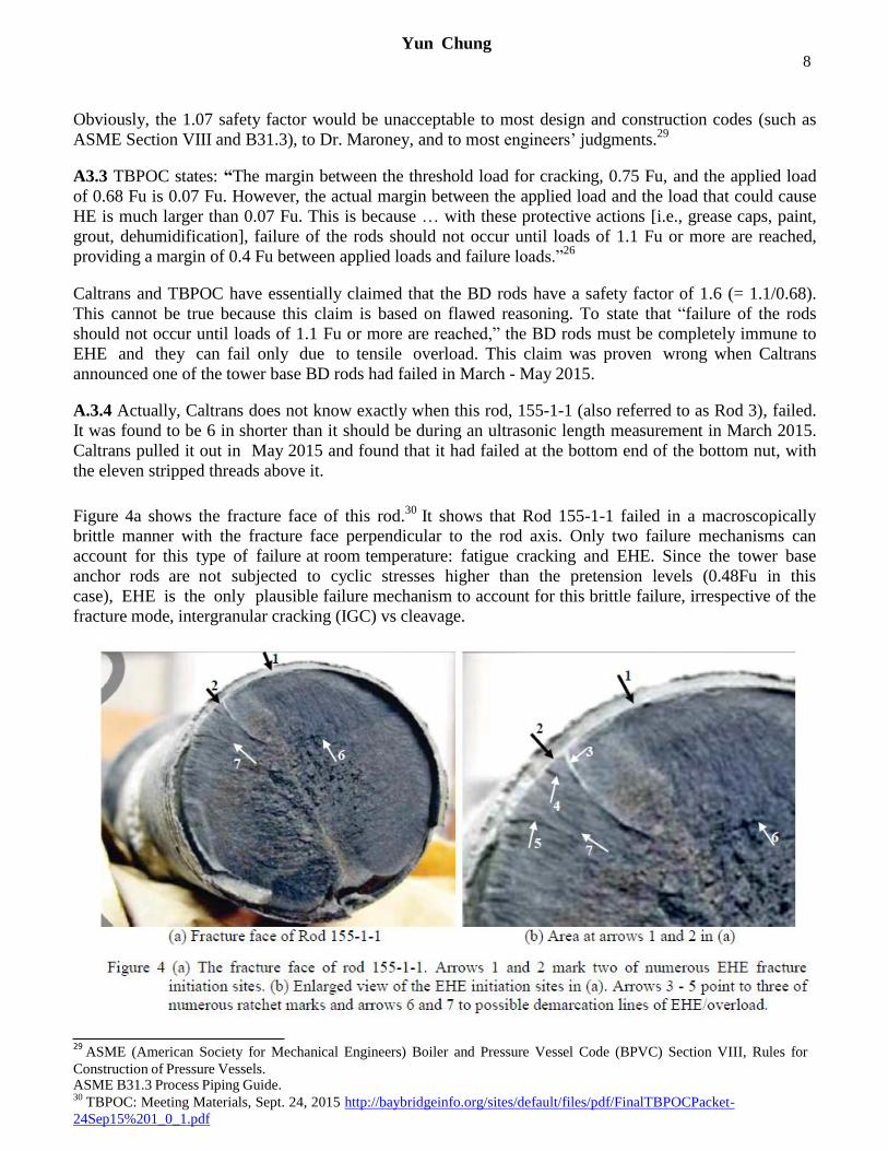
Figures 4c and 4d show IGC and IG facets in the fracture initiation site at arrow 2.31
These IG
indications in the failed tower rod may be compared with those of a Townsend EHE test specimen,
shown in Figures 4e and 4f.32
Exova labeled Figure 4f “Intergranular and Cleavage.” By
comparison, however, Figure 4d has more IG indications than Figure 4f. Exova interpreted Figure 4d as
31 Ref. 30, Fractograph 15, page 595.
“Exova is one of the world's leading laboratory-based testing groups, …” http://www.exova.com/ 32
ibid, page 386.
10 Yun Chung
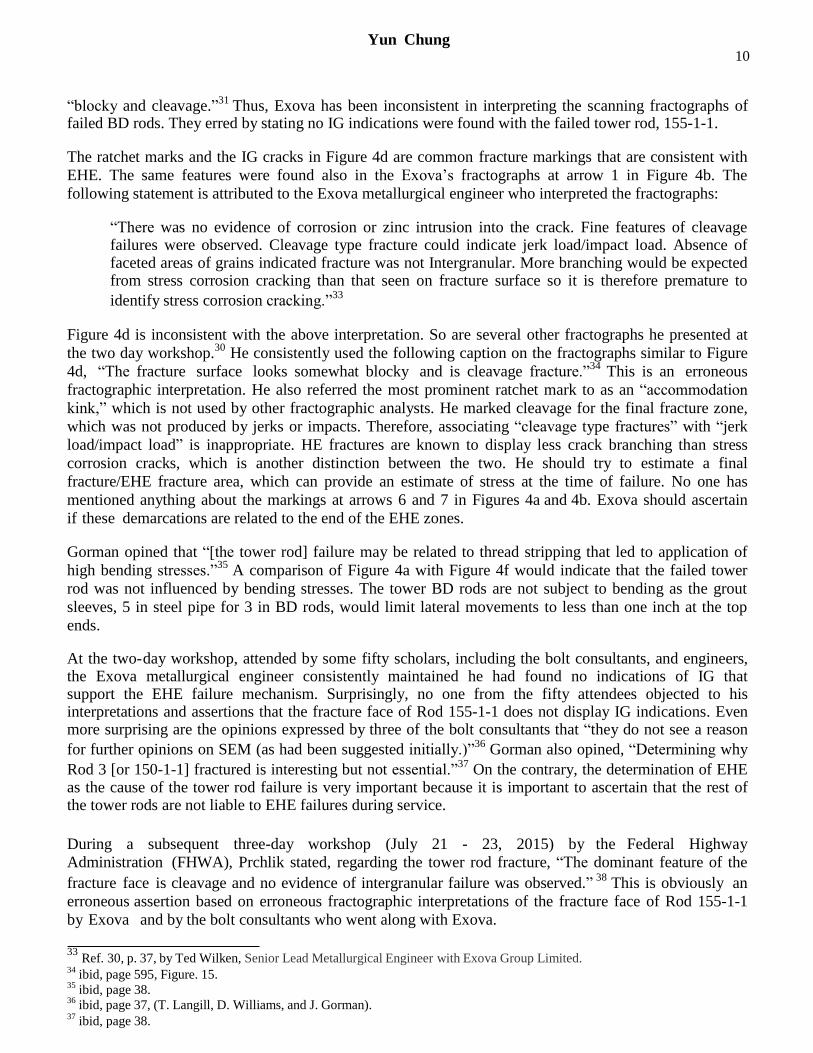
“blocky and cleavage.”31
Thus, Exova has been inconsistent in interpreting the scanning fractographs of failed BD rods. They erred by stating no IG indications were found with the failed tower rod, 155-1-1.
The ratchet marks and the IG cracks in Figure 4d are common fracture markings that are consistent with
EHE. The same features were found also in the Exova’s fractographs at arrow 1 in Figure 4b. The
following statement is attributed to the Exova metallurgical engineer who interpreted the fractographs:
“There was no evidence of corrosion or zinc intrusion into the crack. Fine features of cleavage failures were observed. Cleavage type fracture could indicate jerk load/impact load. Absence of faceted areas of grains indicated fracture was not Intergranular. More branching would be expected from stress corrosion cracking than that seen on fracture surface so it is therefore premature to
identify stress corrosion cracking.”33
Figure 4d is inconsistent with the above interpretation. So are several other fractographs he presented at
the two day workshop.30
He consistently used the following caption on the fractographs similar to Figure
4d, “The fracture surface looks somewhat blocky and is cleavage fracture.”34
This is an erroneous
fractographic interpretation. He also referred the most prominent ratchet mark to as an “accommodation
kink,” which is not used by other fractographic analysts. He marked cleavage for the final fracture zone,
which was not produced by jerks or impacts. Therefore, associating “cleavage type fractures” with “jerk
load/impact load” is inappropriate. HE fractures are known to display less crack branching than stress
corrosion cracks, which is another distinction between the two. He should try to estimate a final
fracture/EHE fracture area, which can provide an estimate of stress at the time of failure. No one has
mentioned anything about the markings at arrows 6 and 7 in Figures 4a and 4b. Exova should ascertain
if these demarcations are related to the end of the EHE zones.
Gorman opined that “[the tower rod] failure may be related to thread stripping that led to application of
high bending stresses.”35
A comparison of Figure 4a with Figure 4f would indicate that the failed tower
rod was not influenced by bending stresses. The tower BD rods are not subject to bending as the grout
sleeves, 5 in steel pipe for 3 in BD rods, would limit lateral movements to less than one inch at the top
ends.
At the two-day workshop, attended by some fifty scholars, including the bolt consultants, and engineers, the Exova metallurgical engineer consistently maintained he had found no indications of IG that support the EHE failure mechanism. Surprisingly, no one from the fifty attendees objected to his interpretations and assertions that the fracture face of Rod 155-1-1 does not display IG indications. Even more surprising are the opinions expressed by three of the bolt consultants that “they do not see a reason
for further opinions on SEM (as had been suggested initially.)”36
Gorman also opined, “Determining why
Rod 3 [or 150-1-1] fractured is interesting but not essential.”37
On the contrary, the determination of EHE as the cause of the tower rod failure is very important because it is important to ascertain that the rest of the tower rods are not liable to EHE failures during service.
During a subsequent three-day workshop (July 21 - 23, 2015) by the Federal Highway
Administration (FHWA), Prchlik stated, regarding the tower rod fracture, “The dominant feature of the
fracture face is cleavage and no evidence of intergranular failure was observed.” 38
This is obviously an
erroneous assertion based on erroneous fractographic interpretations of the fracture face of Rod 155-1-1
by Exova and by the bolt consultants who went along with Exova.
33 Ref. 30, p. 37, by Ted Wilken, Senior Lead Metallurgical Engineer with Exova Group Limited.
34 ibid, page 595, Figure. 15.
35 ibid, page 38.
36 ibid, page 37, (T. Langill, D. Williams, and J. Gorman).
37 ibid, page 38.
11 Yun Chung
Question 4: Did the additional stresses applied during attempts to achieve tower verticality meet
or exceed that safety factor?
Response: Caltrans pulled the tower to one side to counteract the unbalanced loading after the load
transfer of the traffic decks. Caltrans released no details on how the tower base anchor rods were
pretensioned after the load transfer. Therefore, only Caltrans can answer Q4.
A.4 The SFOBB-SAS tower leaned eastward by 18 in when it was first installed according to the San Francisco Chronicle. “When we pulled the tower back, we introduced some tension. It was sustained for
a long time, and while the rods were in standing water.”39
“Maroney acknowledged that tugging the tower into its proper position could have put the water-soaked anchor rods at greater risk of cracking.” However, this might not be entirely correct.
According to a Caltrans press release, the tower pull back was intentional, as follows. “A primary focus
of the workers was balancing the various forces that were at play throughout the operation.
While tensioning the suspender ropes, crews engaged a jacking saddle at the western end of the
bridge to maintain the superstructure’s equilibrium while simultaneously releasing the tower from
its 1.5-foot westward pull, allowing it to regain its vertical stance after being loaded with weight from
the cable and decks. Since the SAS cable is anchored into the eastern end of the roadways, the cable
will naturally pull the tower to the east, so crews pulled the tower west toward Yerba Buena Island
using steel strands that anchored into the island’s bedrock to hold the tower’s position.”40
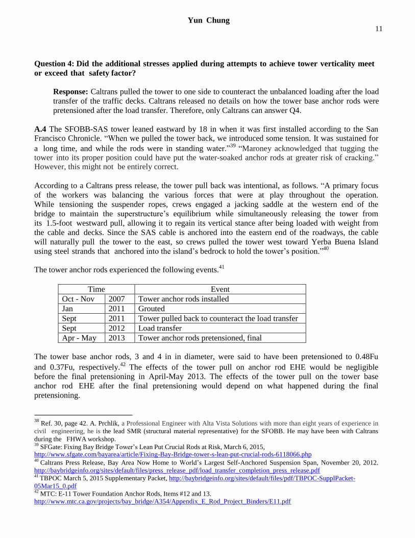
The tower anchor rods experienced the following events.41
Time Event
Oct - Nov 2007 Tower anchor rods installed
Jan 2011 Grouted
Sept 2011 Tower pulled back to counteract the load transfer
Sept 2012 Load transfer
Apr - May 2013 Tower anchor rods pretensioned, final
The tower base anchor rods, 3 and 4 in in diameter, were said to have been pretensioned to 0.48Fu
and 0.37Fu, respectively.42
The effects of the tower pull on anchor rod EHE would be negligible
before the final pretensioning in April-May 2013. The effects of the tower pull on the tower base
anchor rod EHE after the final pretensioning would depend on what happened during the final
pretensioning.
38 Ref. 30, page 42. A. Prchlik, a Professional Engineer with Alta Vista Solutions with more than eight years of experience in
civil engineering, he is the lead SMR (structural material representative) for the SFOBB. He may have been with Caltrans
during the FHWA workshop. 39
SFGate: Fixing Bay Bridge Tower’s Lean Put Crucial Rods at Risk, March 6, 2015, http://www.sfgate.com/bayarea/article/Fixing-Bay-Bridge-tower-s-lean-put-crucial-rods-6118066.php 40
Caltrans Press Release, Bay Area Now Home to World’s Largest Self-Anchored Suspension Span, November 20, 2012.
http://baybridgeinfo.org/sites/default/files/press_release_pdf/load_transfer_completion_press_release.pdf 41
TBPOC March 5, 2015 Supplementary Packet, http://baybridgeinfo.org/sites/default/files/pdf/TBPOC-SupplPacket-
05Mar15_0.pdf 42
MTC: E-11 Tower Foundation Anchor Rods, Items #12 and 13. http://www.mtc.ca.gov/projects/bay_bridge/A354/Appendix_E_Rod_Project_Binders/E11.pdf
12 Yun Chung
If the unknown amount of stresses in the anchor rods due to the tower pull and other
construction activities were relaxed before the final pretensioning, the tower pull would have no
additional effects on the tower anchor rod EHE. If the final pretension load was added to the
existing stresses in the tower anchor rods due to the tower pull, it could have significant additional
effects on the tower EHE failures.
Caltrans released no details on how the tower base anchor rods were pretensioned after the deck
load transfer. Therefore, it is not possible to provide a satisfactory answer to Q4. Maroney’s
concerns may have been based on his personal opinion without reflecting what the tower rods had
actually experienced. Caltrans needs to determine the stress hysteresis of the tower rods.
Question 5: Is it critical for bolt galvanizing to remain intact for long-term corrosion protection,
and is it reasonable to expect galvanizing to remain intact for the 150-year design life?
Response: It would be wrong for Caltrans to state the BD rods are “safe against
environmentally induced hydrogen embrittlement as long as the galvanized coating remains intact.”
Firstly, the HDG zinc coating cannot protect BD rods from EHE failures whether intact or not if the
steel is susceptible to HE. Its effects on EHE are about the same regardless whether the zinc
coating is macroscopically intact or not. Secondly, the zinc coating cannot remain intact during
handling, installing, and pretensioning of BD rods.
It is not reasonable to expect HDG zinc coating to last 150 years without maintenance coating at
the SFOBB-SAS span. Some BD rods on the SAS span can use maintenance coating already.
A5 Depending on how the molten zinc coating on the rods was cooled during the HDG operation, the
solidified zinc coating layer might contain microscopic cracks due to thermal stresses. Also, the HDG
zinc coating can be damaged during handling and particularly during pretensioning. Therefore, it is
unreasonable to expect the HDG zinc coating to remain “intact.” The galvanic corrosion
protection property of the HDG zinc coating is not adversely affected by the microscopic cracks or
other imperfections of the zinc layer. Therefore, for long-term corrosion protection of BD rods, it is
not critical for HDG zinc coating to remain “intact.”
Regarding the effects of the zinc coating integrity on EHE, however, Caltrans states as follows: “The testing program results show that the A354BD rods on the SAS exhibit hydrogen embrittlement thresholds that are higher than their pre-tension stress levels and therefore are safe against environmentally-induced hydrogen
embrittlement as long as the galvanized coating remains intact.”43 This is one of many misstatements that Caltrans and TBPOC have made regarding the BD rod failures due to EHE and their corrective measures. The zinc coating cannot act as a physical barrier against hydrogen diffusion into the steel.
Firstly, the zinc coating gets damaged and cannot remain intact during handling, installing, and pretensioning of BD rods as mentioned before. Secondly, the HDG zinc coating cannot protect BD rods from EHE failures whether intact or not if the steel is susceptible to HE. Its effects on EHE are about the same regardless whether the Zn coating is intact or not. The zinc coating might have a lower permeability of hydrogen than steel; it does not act as a complete physical barrier to hydrogen diffusion. The zinc coating, intact or not, increases
the susceptibility of BD rods to EHE as Townsend pointed out.14 Raymond also stated, a galvanic couple
between the zinc coating and the steel acts “as an in-situ hydrogen generation pump.”44
43 Ref. 5, pp. ES-2 and ES-4.
44 L. Raymond: Acceptance Criterion for Hydrogen Embrittlement Testing of Coated Fasteners,
http://www.asetsdefense.org/documents/Workshops/SustainableSurfaceEngineering2009/Agenda/Thursday/Raymond%20 - %20For%20Posting.pdf
13 Yun Chung
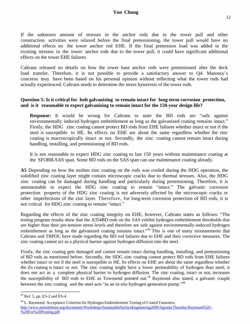
Also, the HDG zinc coating lacks ductility; it can
easily produce numerous cracks when the steel
substrate is tensioned up as shown in Figure 5.45
Therefore, it is erroneous for Caltrans to rely on the
zinc coating being intact for guaranteeing the BD rods
on the SFOBB-SAS span from EHE failures.
The zinc coating will corrode in standing water as
well as due to moisture condensates on the rod
surfaces exposed to the atmosphere. This is also the
very reason why high-strength steel rods can fail due
to EHE when exposed only to the atmospheric
condensates. (An exposure to standing water is not a
necessary condition for EHE.)
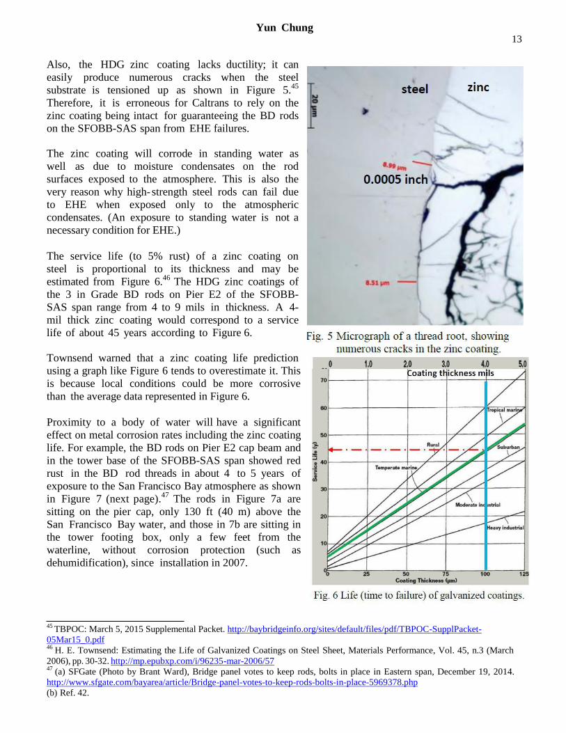
The service life (to 5% rust) of a zinc coating on
steel is proportional to its thickness and may be
estimated from Figure 6.46
The HDG zinc coatings of
the 3 in Grade BD rods on Pier E2 of the SFOBB-
SAS span range from 4 to 9 mils in thickness. A 4-
mil thick zinc coating would correspond to a service
life of about 45 years according to Figure 6.
Townsend warned that a zinc coating life prediction
using a graph like Figure 6 tends to overestimate it. This
is because local conditions could be more corrosive
than the average data represented in Figure 6.
Proximity to a body of water will have a significant
effect on metal corrosion rates including the zinc coating
life. For example, the BD rods on Pier E2 cap beam and
in the tower base of the SFOBB-SAS span showed red
rust in the BD rod threads in about 4 to 5 years of
exposure to the San Francisco Bay atmosphere as shown
in Figure 7 (next page).47
The rods in Figure 7a are
sitting on the pier cap, only 130 ft (40 m) above the
San Francisco Bay water, and those in 7b are sitting in
the tower footing box, only a few feet from the
waterline, without corrosion protection (such as
dehumidification), since installation in 2007.
45 TBPOC: March 5, 2015 Supplemental Packet. http://baybridgeinfo.org/sites/default/files/pdf/TBPOC-SupplPacket-
05Mar15_0.pdf 46
H. E. Townsend: Estimating the Life of Galvanized Coatings on Steel Sheet, Materials Performance, Vol. 45, n.3 (March
2006), pp. 30-32. http://mp.epubxp.com/i/96235-mar-2006/57 47
(a) SFGate (Photo by Brant Ward), Bridge panel votes to keep rods, bolts in place in Eastern span, December 19, 2014.
http://www.sfgate.com/bayarea/article/Bridge-panel-votes-to-keep-rods-bolts-in-place-5969378.php
(b) Ref. 42.
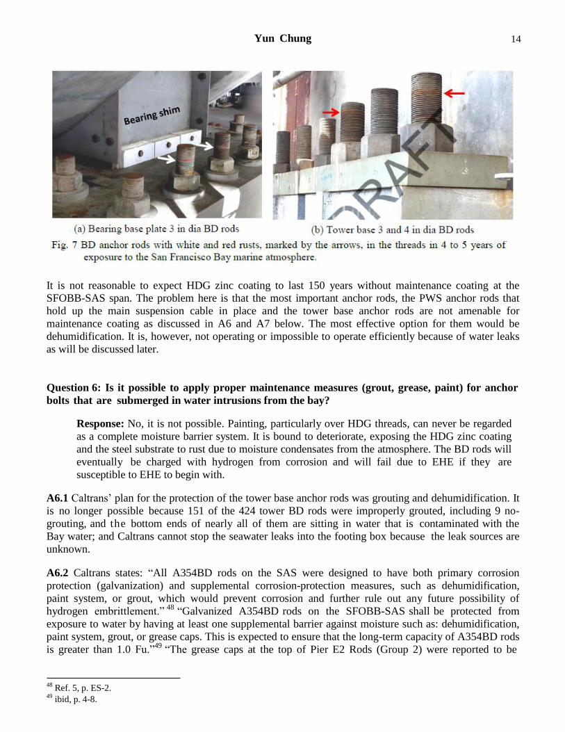
Yun Chung 14
It is not reasonable to expect HDG zinc coating to last 150 years without maintenance coating at the
SFOBB-SAS span. The problem here is that the most important anchor rods, the PWS anchor rods that
hold up the main suspension cable in place and the tower base anchor rods are not amenable for
maintenance coating as discussed in A6 and A7 below. The most effective option for them would be
dehumidification. It is, however, not operating or impossible to operate efficiently because of water leaks
as will be discussed later.
Question 6: Is it possible to apply proper maintenance measures (grout, grease, paint) for anchor
bolts that are submerged in water intrusions from the bay?
Response: No, it is not possible. Painting, particularly over HDG threads, can never be regarded
as a complete moisture barrier system. It is bound to deteriorate, exposing the HDG zinc coating
and the steel substrate to rust due to moisture condensates from the atmosphere. The BD rods will
eventually be charged with hydrogen from corrosion and will fail due to EHE if they are
susceptible to EHE to begin with.
A6.1 Caltrans’ plan for the protection of the tower base anchor rods was grouting and dehumidification. It
is no longer possible because 151 of the 424 tower BD rods were improperly grouted, including 9 no-
grouting, and the bottom ends of nearly all of them are sitting in water that is contaminated with the
Bay water; and Caltrans cannot stop the seawater leaks into the footing box because the leak sources are
unknown.
A6.2 Caltrans states: “All A354BD rods on the SAS were designed to have both primary corrosion
protection (galvanization) and supplemental corrosion-protection measures, such as dehumidification,
paint system, or grout, which would prevent corrosion and further rule out any future possibility of
hydrogen embrittlement.” 48
“Galvanized A354BD rods on the SFOBB-SAS shall be protected from
exposure to water by having at least one supplemental barrier against moisture such as: dehumidification,
paint system, grout, or grease caps. This is expected to ensure that the long-term capacity of A354BD rods
is greater than 1.0 Fu.”49
“The grease caps at the top of Pier E2 Rods (Group 2) were reported to be
48 Ref. 5, p. ES-2.
49 ibid, p. 4-8.
Yun Chung 15
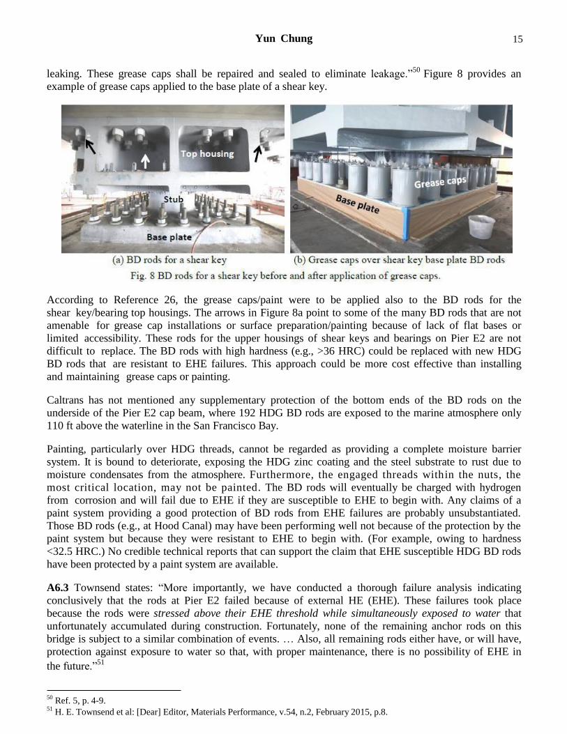
leaking. These grease caps shall be repaired and sealed to eliminate leakage.”50
Figure 8 provides an
example of grease caps applied to the base plate of a shear key.
According to Reference 26, the grease caps/paint were to be applied also to the BD rods for the
shear key/bearing top housings. The arrows in Figure 8a point to some of the many BD rods that are not
amenable for grease cap installations or surface preparation/painting because of lack of flat bases or
limited accessibility. These rods for the upper housings of shear keys and bearings on Pier E2 are not
difficult to replace. The BD rods with high hardness (e.g., >36 HRC) could be replaced with new HDG
BD rods that are resistant to EHE failures. This approach could be more cost effective than installing
and maintaining grease caps or painting.
Caltrans has not mentioned any supplementary protection of the bottom ends of the BD rods on the
underside of the Pier E2 cap beam, where 192 HDG BD rods are exposed to the marine atmosphere only
110 ft above the waterline in the San Francisco Bay.
Painting, particularly over HDG threads, cannot be regarded as providing a complete moisture barrier
system. It is bound to deteriorate, exposing the HDG zinc coating and the steel substrate to rust due to
moisture condensates from the atmosphere. Furthermore, the engaged threads within the nuts, the
most critical location, may not be painted. The BD rods will eventually be charged with hydrogen
from corrosion and will fail due to EHE if they are susceptible to EHE to begin with. Any claims of a
paint system providing a good protection of BD rods from EHE failures are probably unsubstantiated.
Those BD rods (e.g., at Hood Canal) may have been performing well not because of the protection by the
paint system but because they were resistant to EHE to begin with. (For example, owing to hardness
<32.5 HRC.) No credible technical reports that can support the claim that EHE susceptible HDG BD rods
have been protected by a paint system are available.
A6.3 Townsend states: “More importantly, we have conducted a thorough failure analysis indicating
conclusively that the rods at Pier E2 failed because of external HE (EHE). These failures took place
because the rods were stressed above their EHE threshold while simultaneously exposed to water that
unfortunately accumulated during construction. Fortunately, none of the remaining anchor rods on this
bridge is subject to a similar combination of events. … Also, all remaining rods either have, or will have,
protection against exposure to water so that, with proper maintenance, there is no possibility of EHE in
the future.”51
50 Ref. 5, p. 4-9.
51 H. E. Townsend et al: [Dear] Editor, Materials Performance, v.54, n.2, February 2015, p.8.
Yun Chung 16
Gorman et al also state: “the causes of the failure of the 2008 rods [for Shear Keys S1 and S2] generally do not apply to the in-service rods, and these rods do not need to be replaced since robust corrosion
protection measures will maintained.”52
It is difficult to understand how both Townsend and Gorman, as bolt consultants to Caltrans, could have
made the above statements when Caltrans/TBPOC have been actively discussing the water problems in
the bottom ends of the tower base anchor rods since September 2014. Even the reports, References 5 and
26, were concerned about the water in the tower base rods. Reference 5, dated September 30, 2014, states:
“Water was recently observed at a number of Tower Anchorage Anchor Rod locations (Groups 12 and
13).” Reference 26, dated December 30, 2014, states: “After discovering water at the tower base, Caltrans
has extensively tested the water from a number of tower base rods and has determined that the water is
not seawater from the bay.”
Caltrans presented 175 ppm chloride as an average of 13 water samples from the bottom of the tower BD
rods. Since this is much lower than 18,000 ppm chloride for seawater, Caltrans insisted there had
been no seawater contamination. This average included Location 10 (149-1-2), which showed 538 ppm
chloride. Rainwater typically contains only 1 to 2 ppm chloride and the tap water in San Francisco and
Oakland areas contain only around 10 ppm chloride. The most probable explanation for over 500 ppm
chloride, or even 175 ppm chloride, is the seawater intrusion into the footing box, which is sitting in
the Bay water. Later, more water analyses in May 2015 confirmed that the water in the tower base
contained chlorides as high as 7,500 ppm and the ratios of chloride/bromide were consistent with
seawater.53
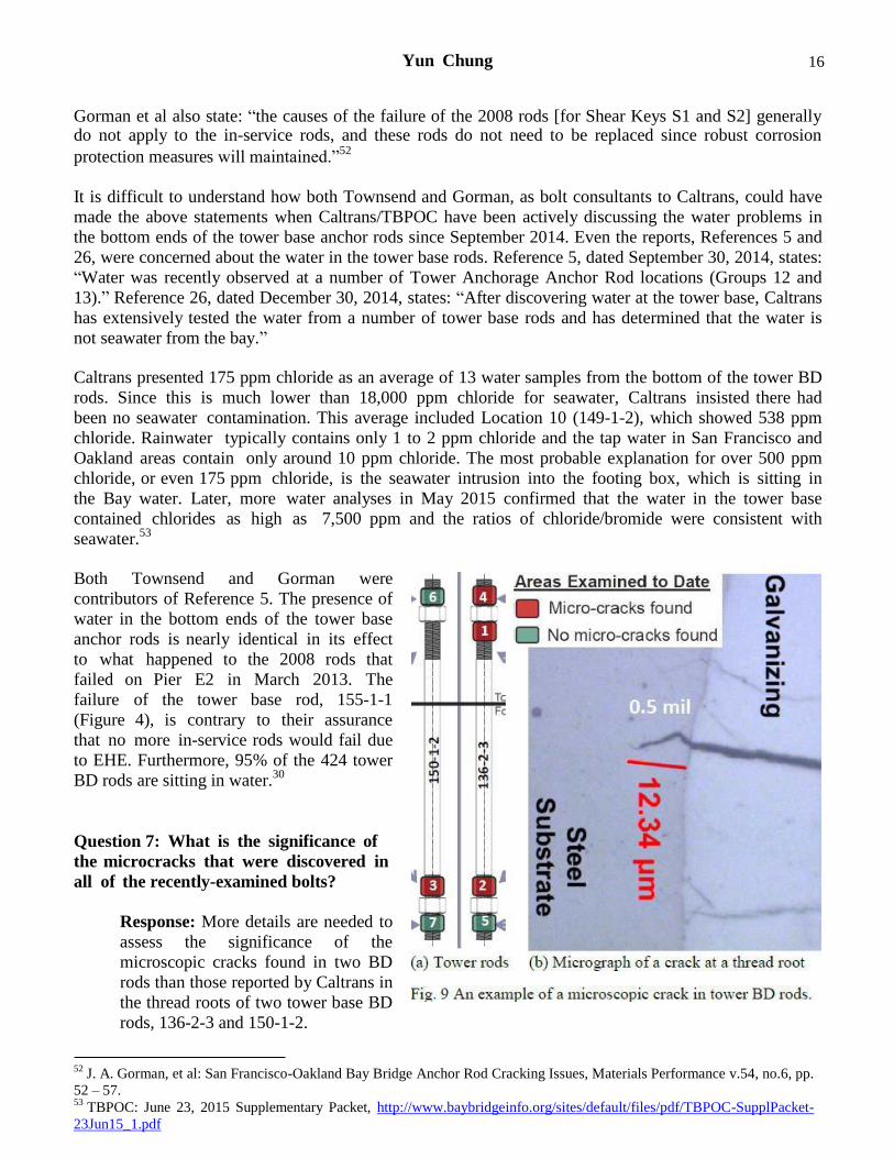
Both Townsend and Gorman were
contributors of Reference 5. The presence of
water in the bottom ends of the tower base
anchor rods is nearly identical in its effect
to what happened to the 2008 rods that
failed on Pier E2 in March 2013. The
failure of the tower base rod, 155-1-1
(Figure 4), is contrary to their assurance
that no more in-service rods would fail due
to EHE. Furthermore, 95% of the 424 tower
BD rods are sitting in water.30
Question 7: What is the significance of
the microcracks that were discovered in
all of the recently-examined bolts?
Response: More details are needed to
assess the significance of the
microscopic cracks found in two BD
rods than those reported by Caltrans in
the thread roots of two tower base BD
rods, 136-2-3 and 150-1-2.
52 J. A. Gorman, et al: San Francisco-Oakland Bay Bridge Anchor Rod Cracking Issues, Materials Performance v.54, no.6, pp.
52 – 57. 53
TBPOC: June 23, 2015 Supplementary Packet, http://www.baybridgeinfo.org/sites/default/files/pdf/TBPOC-SupplPacket-
23Jun15_1.pdf
Yun Chung 17
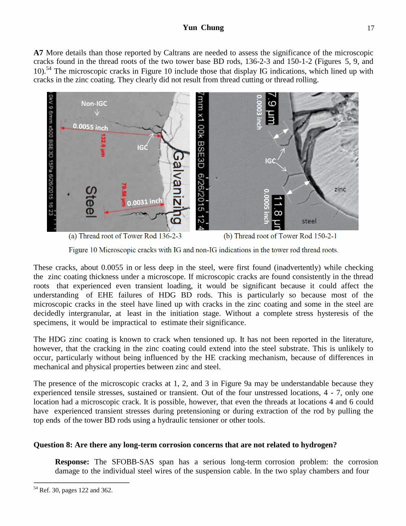
A7 More details than those reported by Caltrans are needed to assess the significance of the microscopic cracks found in the thread roots of the two tower base BD rods, 136-2-3 and 150-1-2 (Figures 5, 9, and
10).54
The microscopic cracks in Figure 10 include those that display IG indications, which lined up with cracks in the zinc coating. They clearly did not result from thread cutting or thread rolling.
These cracks, about 0.0055 in or less deep in the steel, were first found (inadvertently) while checking
the zinc coating thickness under a microscope. If microscopic cracks are found consistently in the thread
roots that experienced even transient loading, it would be significant because it could affect the
understanding of EHE failures of HDG BD rods. This is particularly so because most of the
microscopic cracks in the steel have lined up with cracks in the zinc coating and some in the steel are
decidedly intergranular, at least in the initiation stage. Without a complete stress hysteresis of the
specimens, it would be impractical to estimate their significance.
The HDG zinc coating is known to crack when tensioned up. It has not been reported in the literature,
however, that the cracking in the zinc coating could extend into the steel substrate. This is unlikely to
occur, particularly without being influenced by the HE cracking mechanism, because of differences in
mechanical and physical properties between zinc and steel.
The presence of the microscopic cracks at 1, 2, and 3 in Figure 9a may be understandable because they
experienced tensile stresses, sustained or transient. Out of the four unstressed locations, 4 - 7, only one
location had a microscopic crack. It is possible, however, that even the threads at locations 4 and 6 could
have experienced transient stresses during pretensioning or during extraction of the rod by pulling the
top ends of the tower BD rods using a hydraulic tensioner or other tools.
Question 8: Are there any long-term corrosion concerns that are not related to hydrogen?
Response: The SFOBB-SAS span has a serious long-term corrosion problem: the corrosion
damage to the individual steel wires of the suspension cable. In the two splay chambers and four
54 Ref. 30, pages 122 and 362.
Yun Chung 18
other locations, the HDG steel wires are protected from atmospheric corrosion by dehumidification
only. The fatigue strength of the steel wire would continue to decrease if damaged by
corrosion pits. The strand-socket junctures can fail due to corrosion fatigue unless the
corrosion is stopped now. Caltrans has not released any data on the surface condition of the
parallel wire strands (PWS) and individual wires in the four saddles of the SAS span.
A8.1 The weakest link that will determine the life of the SFOBB SAS span is not the Grade BD anchor
rods or the fatigue cracking of orthotropic steel traffic decks; it is the main suspension cable. This is
because Caltrans has neglected to protect the main cable from corroding where its individual steel wires
are exposed to the moist marine air in the splay chambers, east of Pier E2, and probably also in the tower
cable saddle at T1, and in the two deviation saddles and one jacking saddle at Pier W2. At these six
locations, the individual steel wires of the suspension cable are fully exposed to the surrounding air. The
BD anchor rods may fail due to EHE; they can be replaced with more EHE resistant rods without closing
the bridge. The single, continuous suspension cable for the SFOBB-SAS span cannot be replaced without
first building a support bridge underneath it and closing the bridge for traffic for a long time. The
suspension cable can fail due to corrosion, corrosion fatigue, or both.
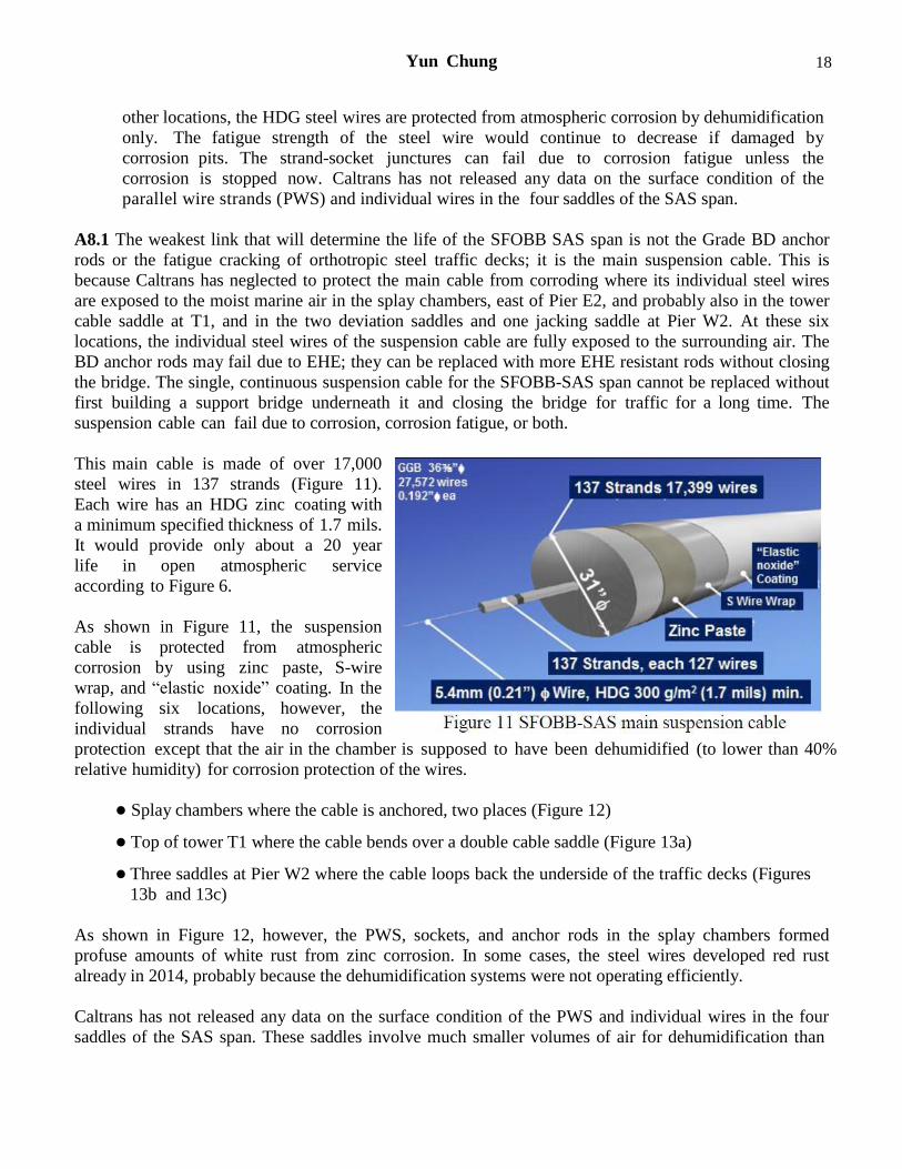
This main cable is made of over 17,000
steel wires in 137 strands (Figure 11).
Each wire has an HDG zinc coating with
a minimum specified thickness of 1.7 mils.
It would provide only about a 20 year
life in open atmospheric service
according to Figure 6.
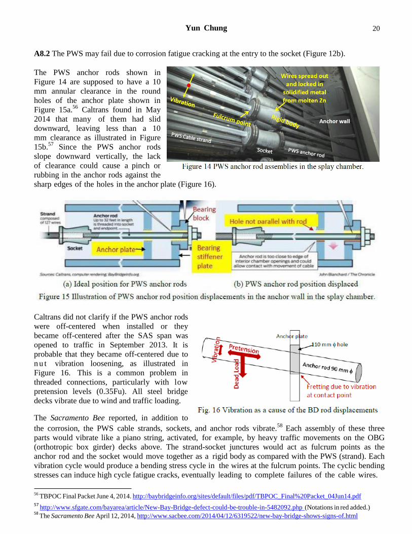
As shown in Figure 11, the suspension
cable is protected from atmospheric
corrosion by using zinc paste, S-wire
wrap, and “elastic noxide” coating. In the
following six locations, however, the
individual strands have no corrosion
protection except that the air in the chamber is supposed to have been dehumidified (to lower than 40%
relative humidity) for corrosion protection of the wires.
Splay chambers where the cable is anchored, two places (Figure 12)
Top of tower T1 where the cable bends over a double cable saddle (Figure 13a)
Three saddles at Pier W2 where the cable loops back the underside of the traffic decks (Figures
13b and 13c)
As shown in Figure 12, however, the PWS, sockets, and anchor rods in the splay chambers formed
profuse amounts of white rust from zinc corrosion. In some cases, the steel wires developed red rust
already in 2014, probably because the dehumidification systems were not operating efficiently.
Caltrans has not released any data on the surface condition of the PWS and individual wires in the four
saddles of the SAS span. These saddles involve much smaller volumes of air for dehumidification than
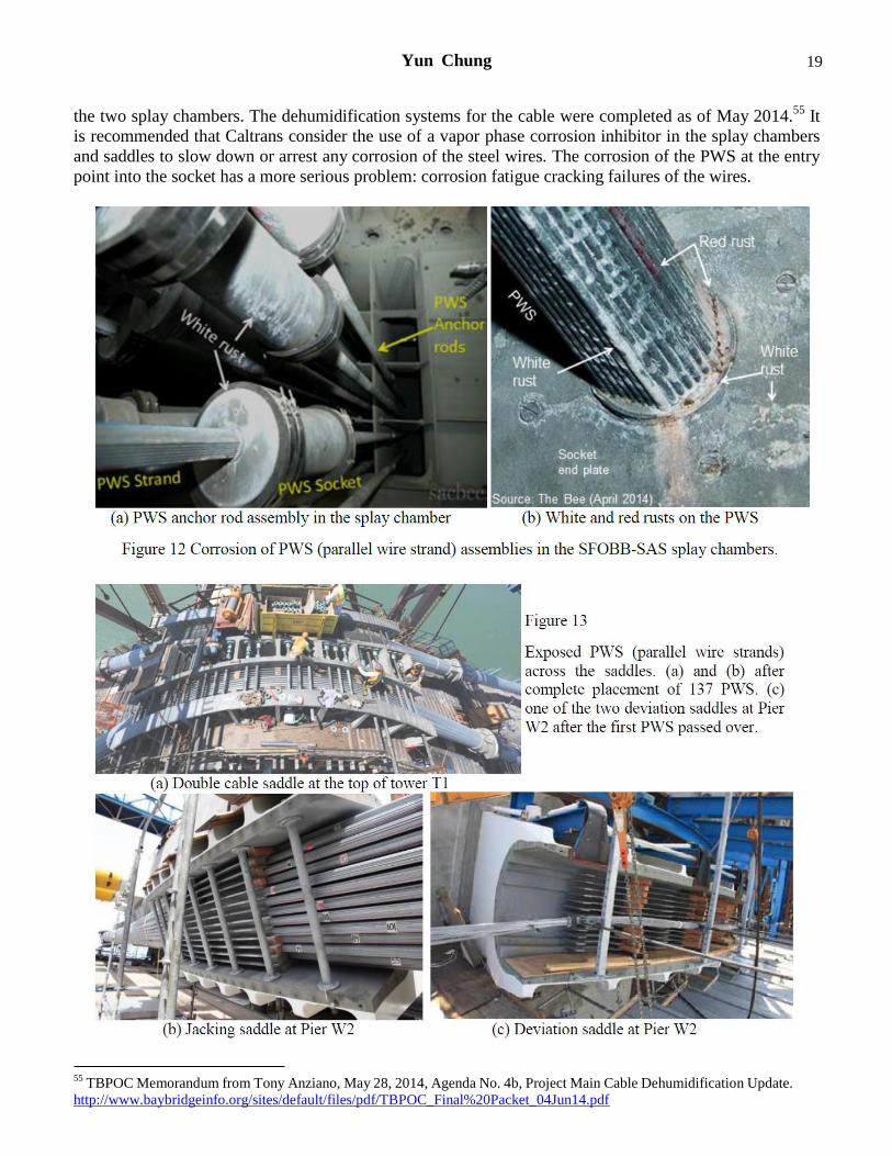
Yun Chung 19
the two splay chambers. The dehumidification systems for the cable were completed as of May 2014.55
It
is recommended that Caltrans consider the use of a vapor phase corrosion inhibitor in the splay chambers
and saddles to slow down or arrest any corrosion of the steel wires. The corrosion of the PWS at the entry
point into the socket has a more serious problem: corrosion fatigue cracking failures of the wires.
55 TBPOC Memorandum from Tony Anziano, May 28, 2014, Agenda No. 4b, Project Main Cable Dehumidification Update.
http://www.baybridgeinfo.org/sites/default/files/pdf/TBPOC_Final%20Packet_04Jun14.pdf
Yun Chung 20
A8.2 The PWS may fail due to corrosion fatigue cracking at the entry to the socket (Figure 12b).
The PWS anchor rods shown in
Figure 14 are supposed to have a 10
mm annular clearance in the round
holes of the anchor plate shown in
Figure 15a.56
Caltrans found in May
2014 that many of them had slid
downward, leaving less than a 10
mm clearance as illustrated in Figure
15b.57
Since the PWS anchor rods
slope downward vertically, the lack
of clearance could cause a pinch or
rubbing in the anchor rods against the
sharp edges of the holes in the anchor plate (Figure 16).
Caltrans did not clarify if the PWS anchor rods
were off-centered when installed or they
became off-centered after the SAS span was
opened to traffic in September 2013. It is
probable that they became off-centered due to
n u t vibration loosening, as illustrated in
Figure 16. This is a common problem in
threaded connections, particularly with low
pretension levels (0.35Fu). All steel bridge
decks vibrate due to wind and traffic loading.
The Sacramento Bee reported, in addition to
the corrosion, the PWS cable strands, sockets, and anchor rods vibrate.58
Each assembly of these three
parts would vibrate like a piano string, activated, for example, by heavy traffic movements on the OBG
(orthotropic box girder) decks above. The strand-socket junctures would act as fulcrum points as the
anchor rod and the socket would move together as a rigid body as compared with the PWS (strand). Each
vibration cycle would produce a bending stress cycle in the wires at the fulcrum points. The cyclic bending
stresses can induce high cycle fatigue cracks, eventually leading to complete failures of the cable wires.
56 TBPOC Final Packet June 4, 2014. http://baybridgeinfo.org/sites/default/files/pdf/TBPOC_Final%20Packet_04Jun14.pdf
57 http://www.sfgate.com/bayarea/article/New-Bay-Bridge-defect-could-be-trouble-in-5482092.php (Notations in red added.)
58 The Sacramento Bee April 12, 2014, http://www.sacbee.com/2014/04/12/6319522/new-bay-bridge-shows-signs-of.html
Yun Chung 21
Whether this might actually happen or not would depend on the vibration amplitude. The greater the
vibration amplitude, the greater the bending stresses (or stress ranges) at the strand-socket junctures and
the shorter will be the wire or strand life.
The PWS wire is made of high carbon (0.78 – 0.85%C) steel that was heat treated and cold drawn to meet
the following tensile strength requirements.59
Tensile strength: 1760 N/mm2
<Fu<1960 N/mm2
or
255 ksi (50 HRC) <Fu< 284 ksi (53 HRC)60
The fatigue limit (or fatigue strength) of the above PWS wire in reverse bending stress cycles would be
around 100 ksi in the absence of corrosion pits or notch effects. At the fulcrum points, the heat of the
molten zinc during locking of the wires in the sockets could have lowered the hardness (or strength). Still,
it may be possible, in the absence of corrosion pits, the stress ranges (∆σ) at the strand-socket junctures
due to traffic-induced vibration could be below the fatigue strength, and thus the PWS wires could
withstand the traffic-induced vibrations indefinitely without failing due to metal fatigue cracking.61
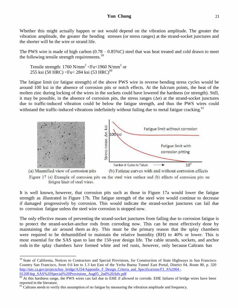
It is well known, however, that corrosion pits such as those in Figure 17a would lower the fatigue
strength as illustrated in Figure 17b. The fatigue strength of the steel wire would continue to decrease
if damaged progressively by corrosion. This would indicate the strand-socket junctures can fail due
to corrosion fatigue unless the steel wire corrosion is stopped now.
The only effective means of preventing the strand-socket junctures from failing due to corrosion fatigue is
to protect the strand-socket-anchor rods from corroding now. This can be most effectively done by
maintaining the air around them as dry. This must be the primary reason that the splay chambers
were required to be dehumidified to maintain the relative humidity (RH) to 40% or lower. This is
most essential for the SAS span to last the 150-year design life. The cable strands, sockets, and anchor
rods in the splay chambers have formed white and red rusts, however, only because Caltrans has
59 State of California, Notices to Contractors and Special Provisions, for Construction of State Highways in San Francisco
Country San Francisco, from 0.6 km to 1.3 km East of the Yerba Buena Tunnel East Portal, District 04, Route 80, p. 320
http://mtc.ca.gov/projects/bay_bridge/A354/Appendix_F_Design_Criteria_and_Specifications/F3_A%2004 -
0120F4sp_SAS%20Special%20Provisions_Aug05_2nd%20Adv.pdf 60
At this hardness range, the PWS wires can fail due to EHE if allowed to corrode. EHE failures of bridge wires have been reported in the literature. 61
Caltrans needs to verify this assumption of no fatigue by measuring the vibration amplitude and frequency.
Yun Chung 22
failed to maintain the rudimentary corrosion engineering requirement: 40% or lower RH for the splay
chambers.
Question 9: An article in the June MP postulated a failure mechanism involving exposure of the
rods to high pH water in the top hats during the interval between grouting and pre-tensioning. Are
there any comments on that possibility?
Response: High pH water in the top hats (bottom of the grout sleeves) can be an ancillary factor
of EHE failures of many of the BD rods but not for all failures. [An exposure to] high pH water
cannot be the root cause of their EHE failures.
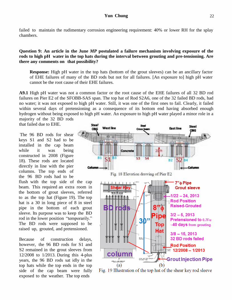
A9.1 High pH water was not a common factor or the root cause of the EHE failures of all 32 BD rod
failures on Pier E2 of the SFOBB-SAS span. The top hat of Rod S2A6, one of the 32 failed BD rods, had
no water; it was not exposed to high pH water. Still, it was one of the first ones to fail. Clearly, it failed
within several days of pretensioning as a consequence of its bottom end having absorbed enough
hydrogen without being exposed to high pH water. An exposure to high pH water played a minor role in a
majority of the 32 BD rods
that failed due to EHE.
The 96 BD rods for shear
keys S1 and S2 had to be
installed in the cap beam
while it was being
constructed in 2008 (Figure
18). These rods are located
directly in line with the pier
columns. The top ends of
the 96 BD rods had to be
flush with the top side of the cap
beam. This required an extra room in
the bottom of grout sleeves, referred
to as the top hat (Figure 19). The top
hat is a 30 in long piece of 8 in steel
pipe in the bottom of each grout
sleeve. Its purpose was to keep the BD
rod in the lower position “temporarily.”
The BD rods were supposed to be
raised up, grouted, and pretensioned.
Because of construction delays,
however, the 96 BD rods for S1 and
S2 remained in the grout sleeves from
12/2008 to 1/2013. During this 4-plus
years, the 96 BD rods sat idly in the
top hats while the top ends in the top
side of the cap beam were fully
exposed to the weather. The top ends
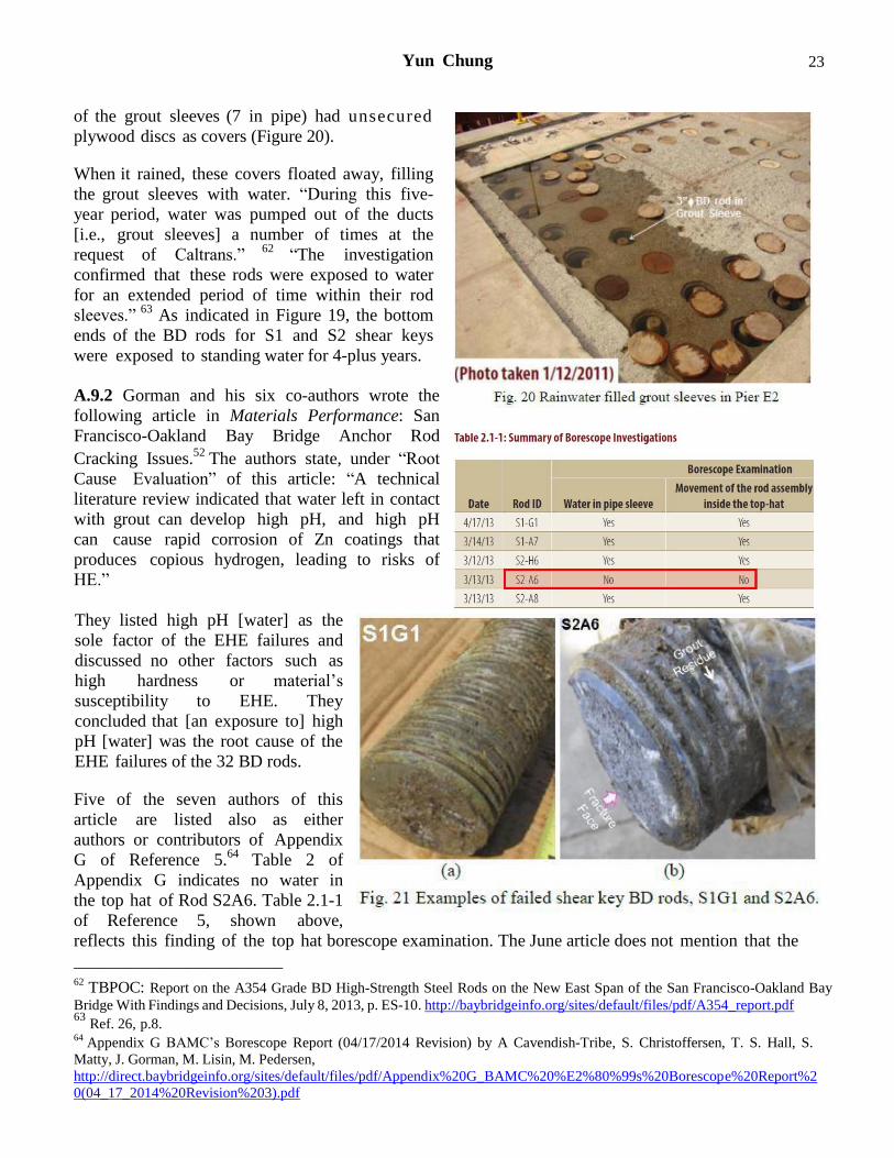
Yun Chung 23
of the grout sleeves (7 in pipe) had unsecured
plywood discs as covers (Figure 20).
When it rained, these covers floated away, filling
the grout sleeves with water. “During this five-
year period, water was pumped out of the ducts
[i.e., grout sleeves] a number of times at the
request of Caltrans.” 62
“The investigation
confirmed that these rods were exposed to water
for an extended period of time within their rod
sleeves.” 63
As indicated in Figure 19, the bottom
ends of the BD rods for S1 and S2 shear keys
were exposed to standing water for 4-plus years.
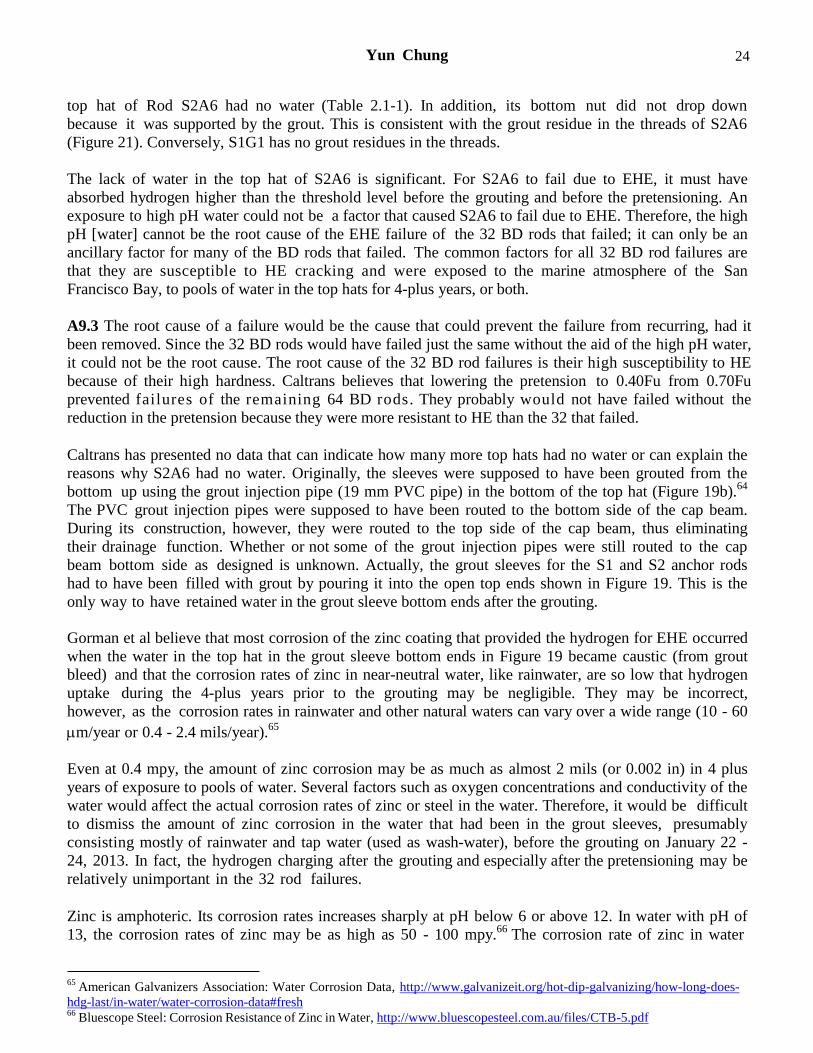
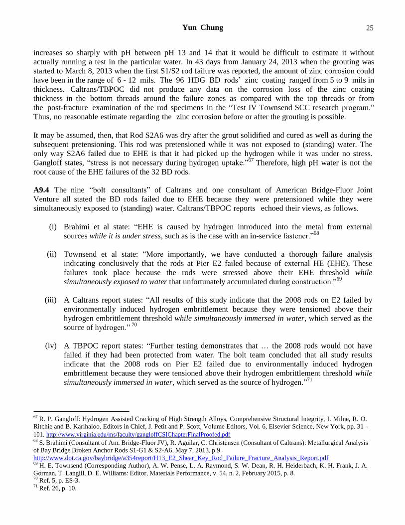
A.9.2 Gorman and his six co-authors wrote the
following article in Materials Performance: San
Francisco-Oakland Bay Bridge Anchor Rod
Cracking Issues.52
The authors state, under “Root
Cause Evaluation” of this article: “A technical
literature review indicated that water left in contact
with grout can develop high pH, and high pH
can cause rapid corrosion of Zn coatings that
produces copious hydrogen, leading to risks of
HE.”
They listed high pH [water] as the
sole factor of the EHE failures and
discussed no other factors such as
high hardness or material’s
susceptibility to EHE. They
concluded that [an exposure to] high
pH [water] was the root cause of the
EHE failures of the 32 BD rods.
Five of the seven authors of this
article are listed also as either
authors or contributors of Appendix
G of Reference 5.64
Table 2 of
Appendix G indicates no water in
the top hat of Rod S2A6. Table 2.1-1
of Reference 5, shown above,
reflects this finding of the top hat borescope examination. The June article does not mention that the
________________________
62 TBPOC: Report on the A354 Grade BD High-Strength Steel Rods on the New East Span of the San Francisco-Oakland Bay
Bridge With Findings and Decisions, July 8, 2013, p. ES-10. http://baybridgeinfo.org/sites/default/files/pdf/A354_report.pdf 63
Ref. 26, p.8. 64
Appendix G BAMC’s Borescope Report (04/17/2014 Revision) by A Cavendish-Tribe, S. Christoffersen, T. S. Hall, S.
Matty, J. Gorman, M. Lisin, M. Pedersen,
http://direct.baybridgeinfo.org/sites/default/files/pdf/Appendix%20G_BAMC%20%E2%80%99s%20Borescope%20Report%2
0(04_17_2014%20Revision%203).pdf
Yun Chung 24
top hat of Rod S2A6 had no water (Table 2.1-1). In addition, its bottom nut did not drop down
because it was supported by the grout. This is consistent with the grout residue in the threads of S2A6
(Figure 21). Conversely, S1G1 has no grout residues in the threads.
The lack of water in the top hat of S2A6 is significant. For S2A6 to fail due to EHE, it must have
absorbed hydrogen higher than the threshold level before the grouting and before the pretensioning. An
exposure to high pH water could not be a factor that caused S2A6 to fail due to EHE. Therefore, the high
pH [water] cannot be the root cause of the EHE failure of the 32 BD rods that failed; it can only be an
ancillary factor for many of the BD rods that failed. The common factors for all 32 BD rod failures are
that they are susceptible to HE cracking and were exposed to the marine atmosphere of the San
Francisco Bay, to pools of water in the top hats for 4-plus years, or both.
A9.3 The root cause of a failure would be the cause that could prevent the failure from recurring, had it
been removed. Since the 32 BD rods would have failed just the same without the aid of the high pH water,
it could not be the root cause. The root cause of the 32 BD rod failures is their high susceptibility to HE
because of their high hardness. Caltrans believes that lowering the pretension to 0.40Fu from 0.70Fu
prevented failures of the remaining 64 BD rods. They probably would not have failed without the
reduction in the pretension because they were more resistant to HE than the 32 that failed.
Caltrans has presented no data that can indicate how many more top hats had no water or can explain the
reasons why S2A6 had no water. Originally, the sleeves were supposed to have been grouted from the
bottom up using the grout injection pipe (19 mm PVC pipe) in the bottom of the top hat (Figure 19b).64
The PVC grout injection pipes were supposed to have been routed to the bottom side of the cap beam.
During its construction, however, they were routed to the top side of the cap beam, thus eliminating
their drainage function. Whether or not some of the grout injection pipes were still routed to the cap
beam bottom side as designed is unknown. Actually, the grout sleeves for the S1 and S2 anchor rods
had to have been filled with grout by pouring it into the open top ends shown in Figure 19. This is the
only way to have retained water in the grout sleeve bottom ends after the grouting.
Gorman et al believe that most corrosion of the zinc coating that provided the hydrogen for EHE occurred
when the water in the top hat in the grout sleeve bottom ends in Figure 19 became caustic (from grout
bleed) and that the corrosion rates of zinc in near-neutral water, like rainwater, are so low that hydrogen
uptake during the 4-plus years prior to the grouting may be negligible. They may be incorrect,
however, as the corrosion rates in rainwater and other natural waters can vary over a wide range (10 - 60
m/year or 0.4 - 2.4 mils/year).65
Even at 0.4 mpy, the amount of zinc corrosion may be as much as almost 2 mils (or 0.002 in) in 4 plus
years of exposure to pools of water. Several factors such as oxygen concentrations and conductivity of the
water would affect the actual corrosion rates of zinc or steel in the water. Therefore, it would be difficult
to dismiss the amount of zinc corrosion in the water that had been in the grout sleeves, presumably
consisting mostly of rainwater and tap water (used as wash-water), before the grouting on January 22 -
24, 2013. In fact, the hydrogen charging after the grouting and especially after the pretensioning may be
relatively unimportant in the 32 rod failures.
Zinc is amphoteric. Its corrosion rates increases sharply at pH below 6 or above 12. In water with pH of
13, the corrosion rates of zinc may be as high as 50 - 100 mpy.66
The corrosion rate of zinc in water
65 American Galvanizers Association: Water Corrosion Data, http://www.galvanizeit.org/hot-dip-galvanizing/how-long-does-
hdg-last/in-water/water-corrosion-data#fresh 66
Bluescope Steel: Corrosion Resistance of Zinc in Water, http://www.bluescopesteel.com.au/files/CTB-5.pdf
Yun Chung 25
increases so sharply with pH between pH 13 and 14 that it would be difficult to estimate it without
actually running a test in the particular water. In 43 days from January 24, 2013 when the grouting was
started to March 8, 2013 when the first S1/S2 rod failure was reported, the amount of zinc corrosion could
have been in the range of 6 - 12 mils. The 96 HDG BD rods’ zinc coating ranged from 5 to 9 mils in
thickness. Caltrans/TBPOC did not produce any data on the corrosion loss of the zinc coating
thickness in the bottom threads around the failure zones as compared with the top threads or from
the post-fracture examination of the rod specimens in the “Test IV Townsend SCC research program.”
Thus, no reasonable estimate regarding the zinc corrosion before or after the grouting is possible.
It may be assumed, then, that Rod S2A6 was dry after the grout solidified and cured as well as during the
subsequent pretensioning. This rod was pretensioned while it was not exposed to (standing) water. The
only way S2A6 failed due to EHE is that it had picked up the hydrogen while it was under no stress.
Gangloff states, “stress is not necessary during hydrogen uptake.”67
Therefore, high pH water is not the
root cause of the EHE failures of the 32 BD rods.
A9.4 The nine “bolt consultants” of Caltrans and one consultant of American Bridge-Fluor Joint
Venture all stated the BD rods failed due to EHE because they were pretensioned while they were
simultaneously exposed to (standing) water. Caltrans/TBPOC reports echoed their views, as follows.
(i) Brahimi et al state: “EHE is caused by hydrogen introduced into the metal from external
sources while it is under stress, such as is the case with an in-service fastener.”68
(ii) Townsend et al state: “More importantly, we have conducted a thorough failure analysis
indicating conclusively that the rods at Pier E2 failed because of external HE (EHE). These
failures took place because the rods were stressed above their EHE threshold while
simultaneously exposed to water that unfortunately accumulated during construction.”69
(iii) A Caltrans report states: “All results of this study indicate that the 2008 rods on E2 failed by
environmentally induced hydrogen embrittlement because they were tensioned above their
hydrogen embrittlement threshold while simultaneously immersed in water, which served as the
source of hydrogen.” 70
(iv) A TBPOC report states: “Further testing demonstrates that … the 2008 rods would not have
failed if they had been protected from water. The bolt team concluded that all study results
indicate that the 2008 rods on Pier E2 failed due to environmentally induced hydrogen
embrittlement because they were tensioned above their hydrogen embrittlement threshold while
simultaneously immersed in water, which served as the source of hydrogen.”71
67 R. P. Gangloff: Hydrogen Assisted Cracking of High Strength Alloys, Comprehensive Structural Integrity, I. Milne, R. O.
Ritchie and B. Karihaloo, Editors in Chief, J. Petit and P. Scott, Volume Editors, Vol. 6, Elsevier Science, New York, pp. 31 -
101. http://www.virginia.edu/ms/faculty/gangloffCSIChapterFinalProofed.pdf 68
S. Brahimi (Consultant of Am. Bridge-Fluor JV), R. Aguilar, C. Christensen (Consultant of Caltrans): Metallurgical Analysis
of Bay Bridge Broken Anchor Rods S1-G1 & S2-A6, May 7, 2013, p.9.
http://www.dot.ca.gov/baybridge/a354report/H13_E2_Shear_Key_Rod_Failure_Fracture_Analysis_Report.pdf 69
H. E. Townsend (Corresponding Author), A. W. Pense, L. A. Raymond, S. W. Dean, R. H. Heiderbach, K. H. Frank, J. A.
Gorman, T. Langill, D. E. Williams: Editor, Materials Performance, v. 54, n. 2, February 2015, p. 8. 70
Ref. 5, p. ES-3. 71
Ref. 26, p. 10.
Yun Chung 26
The S1 and S2 BD rods were under tension while simultaneously immersed in water for only 3 to 6 days
(Figure 19), not long enough time for zinc/steel to corrode, generate hydrogen, for it to diffuse into the
BD rods to reach a hydrogen concentration higher than a threshold level, and cause HE cracking.
The above misconception about the role of stress came about because Caltrans, TBPOC, and the bolt
consultants all have treated EHE exactly the same as, or interchangeably with, SCC. In SCC, the
stressing must be simultaneous with corroding. In EHE, however, the stressing can occur after
corroding, during which hydrogen can diffuse into the metal with or without being stressed. This is
the primary reason why EHE may not be treated interchangeably with SCC. Townsend et al state: “we
have opted to use the terms SCC and EHE interchangeably, and do not see any reason for this to be a
source of confusion.”57
This practice needs to stop to avoid confusion. This is the source of the
erroneous conclusion by the bolt consultants that the BD rods on the SAS span absorbed hydrogen and
developed EHE cracking all within three to six days after pretensioning. There are several distinctive
differences between EHE and SCC. Popov states: “Hydrogen embrittlement is different from stress
corrosion cracking (SCC), …”72
A9.5 A Caltrans report also states: “The 2008 rods would not have failed if they were protected from
water.”73
This may be referring to a pool of water in the grout sleeves. Literally speaking, however, it is
impossible to protect the BD rods on Pier E2 from water. This is because the BD rods with high hardness
can fail, due to EHE, in atmospheric services without being exposed to a pool of water. Consider how
Rod S2A6 could have failed due to EHE without being exposed to a pool of water.
The 96 BD rods for S1 and S2 comprise 60 rods of Type A (17 ft long) and 36 rods of Type B (10 ft long).
The internal volumes of the grout sleeves are about 3 and 5 ft3 for Type A and Type B, respectively. The
moisture in the air inside the grout sleeves would condense cyclically or nightly on the rod as well as the
grout sleeve surfaces and drip down. A pool of condensates would form in the top hats over time if the
grout injection pipe does not function as a drain. Even if the condensates drained, the bottom threads
within the nuts would remain wet more or less continuously in the bottom of the grout sleeves inside the
concrete cap beam.
A9.6 Thus, it is possible that the bottom threads of S2A6 could have developed enough corrosion in
4-plus years without being exposed to standing water, absorbing enough hydrogen under no stress, and
leading to EHE when pretensioned. Most of the hydrogen absorption necessary for EHE occurred during
the 4-plus years, before the grouting, while the BD rods were under no tension. Many of the BD rods were
probably exposed to pools of water during this period. By comparison, the amount of hydrogen absorption
by the BD rods after the pretensioning, during the several days between March 2 - 5 ~ 8 - 15, 2013 (Figure
19b), would be insignificant.
It was wrong, therefore, for Caltrans/TBPOC/bolt consultants to state, “The bolt team concluded that all
study results indicate that the 2008 rods on Pier E2 failed due to environmentally induced hydrogen
embrittlement because they were tensioned above their hydrogen embrittlement threshold while
simultaneously immersed in water, which served as the source of hydrogen.”71
It was also wrong for
Gorman et al to cite the high pH water as the root cause of the BD rod failures on Pier E2 of the SFOBB-
SAS span.52
72 B. N. Popov: Corrosion Engineering, Principles and Solved Problems, Elsevier, 2015, p. 345.
73 Ref. 5, p.ES-4.