
Viaduc de Millau, France Τα Νέα
50
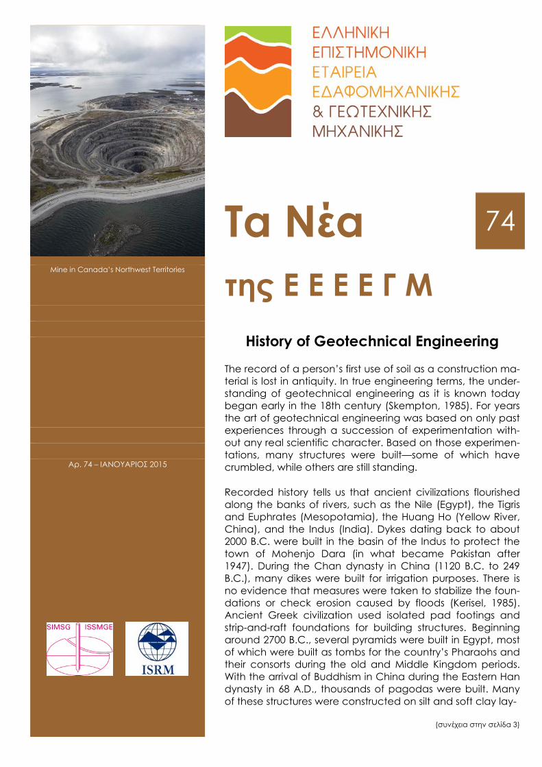
Viaduc de Millau, France Τα Νέα 74 Mine in Canada’s Northwest Territories της Ε Ε Ε Ε Γ Μ History of Geotechnical Engineering The record of a person’s first use of soil as a construction ma- terial is lost in antiquity. In true engineering terms, the under- standing of geotechnical engineering as it is known today began early in the 18th century (Skempton, 1985). For years the art of geotechnical engineering was based on only past experiences through a succession of experimentation with- out any real scientific character. Based on those experimen- tations, many structures were built—some of which have crumbled, while others are still standing. Recorded history tells us that ancient civilizations flourished along the banks of rivers, such as the Nile (Egypt), the Tigris and Euphrates (Mesopotamia), the Huang Ho (Yellow River, China), and the Indus (India). Dykes dating back to about 2000 B.C. were built in the basin of the Indus to protect the town of Mohenjo Dara (in what became Pakistan after 1947). During the Chan dynasty in China (1120 B.C. to 249 B.C.), many dikes were built for irrigation purposes. There is no evidence that measures were taken to stabilize the foun- dations or check erosion caused by floods (Kerisel, 1985). Ancient Greek civilization used isolated pad footings and strip-and-raft foundations for building structures. Beginning around 2700 B.C., several pyramids were built in Egypt, most of which were built as tombs for the country’s Pharaohs and their consorts during the old and Middle Kingdom periods. With the arrival of Buddhism in China during the Eastern Han dynasty in 68 A.D., thousands of pagodas were built. Many of these structures were constructed on silt and soft clay lay- (συνέχεια στην σελίδα 3) Αρ. 74 – ΙΑΝΟΥΑΡΙΟΣ 2015
Transcript of Viaduc de Millau, France Τα Νέα
Viaduc de Millau, France
Τα Νέα 74
Mine in Canada’s Northwest Territories της Ε Ε Ε Ε Γ Μ
History of Geotechnical Engineering
The record of a person’s first use of soil as a construction ma-terial is lost in antiquity. In true engineering terms, the under-standing of geotechnical engineering as it is known today began early in the 18th century (Skempton, 1985). For years the art of geotechnical engineering was based on only past experiences through a succession of experimentation with-out any real scientific character. Based on those experimen-tations, many structures were built—some of which have crumbled, while others are still standing.
Recorded history tells us that ancient civilizations flourished along the banks of rivers, such as the Nile (Egypt), the Tigris and Euphrates (Mesopotamia), the Huang Ho (Yellow River, China), and the Indus (India). Dykes dating back to about 2000 B.C. were built in the basin of the Indus to protect the town of Mohenjo Dara (in what became Pakistan after 1947). During the Chan dynasty in China (1120 B.C. to 249 B.C.), many dikes were built for irrigation purposes. There is no evidence that measures were taken to stabilize the foun-dations or check erosion caused by floods (Kerisel, 1985). Ancient Greek civilization used isolated pad footings and strip-and-raft foundations for building structures. Beginning around 2700 B.C., several pyramids were built in Egypt, most of which were built as tombs for the country’s Pharaohs and their consorts during the old and Middle Kingdom periods. With the arrival of Buddhism in China during the Eastern Han dynasty in 68 A.D., thousands of pagodas were built. Many of these structures were constructed on silt and soft clay lay-
(συνέχεια στην σελίδα 3)
Αρ. 74 – ΙΑΝΟΥΑΡΙΟΣ 2015
ΤΑ ΝΕΑ ΤΗΣ ΕΕΕΕΓΜ – Αρ. 74 – ΙΑΝΟΥΑΡΙΟΣ 2015 Σελίδα 2
Π Ε Ρ Ι Ε Χ Ο Μ Ε Ν Α
History of Geotechnical Engineering 1
Άρθρα 1
- Αποσπάσματα από τα βιβλία Ralph Peck, Educator and Engineer: The Essence of the Man και Judgement in Geotechnical Engineering, The Professional Legacy of Ralph Peck 6
- Geothermal Energy for Heating and Cooling: Full- Scale Testing and Numerical Modelling 9
- Design and Construction of A Cement Stabilised- Shored Reinforced Soil Wall 12
Νέα από τις Ελληνικές και Διεθνείς Γεωτεχνικές Ενώσεις 22
Προσεχείς Γεωτεχνικές Εκδηλώσεις: 23
- 1st IAGEM International Conference 2015 Geotechnical, Structural and Environmental Monitoring of Civil Works 23
- 2nd International Geo-Cultural Symposium "Sigri 2015" 23
- Numerical Analysis in Geotechnics (NAG2015) 24
- International Benchmark 2015 - 13th International Benchmark on the Numerical Analysis of Dams 25
- International Symposium on Geohazards and Geomechanics 25
- 5th Fifth International Conference on Geotechnique, Construction Materials and Environment, GEOMATE 2015 26
- SAHC 2016 10th international Conference on Structural Analysis of Historical Constructions 27
- AfriRock 2017 1st African Regional Rock Mechanics Symposium 28
Ενδιαφέροντα Γεωτεχνικά Νέα 30 - Final Independent Expert Panel Investigation Report
on Mount Polley Tailings Facility Breach in B.C., Canada 30
- Film de la construction du centre des congrès - 102014 from Rennes, Ville et Métropole 30
- Sinkholes - Natural Phenomena and Headache 30
- Litochovice: an interesting highway landslide in the Czech Republic 32
Ενδιαφέροντα – Σεισμοί 33
- Σεισμός Νεπάλ 2015 Προκαταρκτικά Αποτελέσματα 33
- LA Installs Shake-Resistant Water Pipes at 'Epicenter' of 1994 Upheaval 33
- Volcano Facts and Types of Volcanoes 33
Ενδιαφέροντα – Περιβάλλον 36
- Are volcanoes the energy source of the future? 36
- A Bamboo Tower That Produces Water From Air 38
- Η ελλάτωση της τιμής του αργού πετρελαίου και η ιωσιμότητα της παραγωγής από σχιστολιθικά πετρώ- ματα και άλλες μη «συμβατικές» περιπτώσεις 40
Ενδιαφέροντα – Λοιπά 41
- Amazing Feats of Engineering! 41
- The Tallest Bridge in The World 42
- The Slauerhoffbrug "Flying Drawbridge" and Other Impressive Dutch Overpasses 43
- The Best New Tall Buildings on the Planet 43
Νέες Εκδόσεις στις Γεωτεχνικές Επιστήμες 48
Ηλεκτρονικά Περιοδικά 49
ΤΑ ΝΕΑ ΤΗΣ ΕΕΕΕΓΜ – Αρ. 74 – ΙΑΝΟΥΑΡΙΟΣ 2015 Σελίδα 3
(συνέχεια από την πρώτη σελίδα)
ers. In some cases the foundation pressure exceeded the load-bearing capacity of the soil and thereby caused exten-sive structural damage.
One of the most famous examples of problems related to soil-bearing capacity in the construction of structures prior to the 18th century is the Leaning Tower of Pisa in Italy. Construction of the tower began in 1173 A.D. when the Republic of Pisa was flourishing and continued in various stages for over 200 years. The structure weighs about 15,700 metric tons and is supported by a circular base hav-ing a diameter of 20 m. The tower has tilted in the past to the east, north, west and, finally, to the south. Recent in-vestigations showed that a weak clay layer exists at a depth of about 11 m below the ground surface, compres-sion of which caused the tower to tilt. It became more than 5 m out of plumb with the 54 m height. The tower was closed in 1990 because it was feared that it would either fall over or collapse. It has recently been stabilized by ex-cavating soil from under the north side of the tower. About 70 metric tons of earth were removed in 41 separate ex-tractions that spanned the width of the tower. As the ground gradually settled to fill the resulting space, the tilt of the tower eased. The tower now leans 5 degrees. The half-degree change is not noticeable, but it makes the structure considerably more stable. After encountering sev-eral foundation-related problems during construction over centuries past, engineers and scientists began to address the properties and behavior of soils in a more methodical manner starting in the early part of the 18th century. Based on the emphasis and the nature of study in the area of ge-otechnical engineering, the time span extending from 1700 to 1927 can be divided into four major periods (Skempton, 1985):
1. Pre-classical (1700 to 1776 A.D.) 2. Classical soil mechanics—Phase I (1776 to 1856 A.D.) 3. Classical soil mechanics—Phase II (1856 to 1910 A.D.) 4. Modern soil mechanics (1910 to 1927 A.D.)
Preclassical Period of Soil Mechanics (1700–1776)
This period concentrated on studies relating to natural slope and unit weights of various types of soils as well as the semiempirical earth pressure theories. In 1717 a French royal engineer, Henri Gautier (1660–1737), studied the natural slopes of soils when tipped in a heap for formulating the design procedures of retaining walls. The natural slope is what we now refer to as the angle of repose. According to this study, the natural slopes of clean dry sand and ordi-nary earth were 31° and 45°, respectively. Also, the unit weights of clean dry sand and ordinary earth were recom-mended to be 18.1 kN/m3 and 13.4 kN/m3, respectively. In 1729, Bernard Forest de Belidor (1694–1761) published a textbook for military and civil engineers in France. In the book, he proposed a theory for lateral earth pressure on retaining walls that was a follow-up to Gautier’s (1717) original study.
The first laboratory model test results on a 76-mm-high retaining wall built with sand backfill were reported in 1746 by a French engineer, Francois Gadroy (1705–1759), who observed the existence of slip planes in the soil at failure. Gadroy’s study was later summarized by J. J. Mayniel in 1808. Another notable contribution during this period is that by the French engineer Jean Rodolphe Perronet (1708–1794), who studied slope stability around 1769 and distin-guished between intact ground and fills.
Classical Soil Mechanics—Phase I (1776–1856)
During this period, most of the developments in the area of geotechnical engineering came from engineers and scien-tists in France. In the preclassical period, practically all the-
oretical considerations used in calculating lateral earth pressure on retaining walls were based on an arbitrarily based failure surface in soil. In his famous paper presented in 1776, French scientist Charles Augustin Coulomb (1736–1806) used the principles of calculus for maxima and mini-ma to determine the true position of the sliding surface in soil behind a retaining wall. In this analysis, Coulomb used the laws of friction and cohesion for solid bodies. In 1790, the distinguished French civil engineer, Gaspard Claire Ma-rie Riche de Brony (1755–1839) included Coulomb’s theory in his leading textbook, Nouvelle Architecture Hydraulique (Vol. 1). In 1820, special cases of Coulomb’s work were studied by French engineer Jacques Frederic Francais (1775–1833) and by French applied-mechanics professor Claude Louis Marie Henri Navier (1785–1836). These spe-cial cases related to inclined backfills and backfills support-ing surcharge. In 1840, Jean Victor Poncelet (1788–1867), an army engineer and professor of mechanics, extended Coulomb’s theory by providing a graphical method for de-termining the magnitude of lateral earth pressure on verti-cal and inclined retaining walls with arbitrarily broken po-lygonal ground surfaces. Poncelet was also the first to use the symbol f for soil friction angle. He also provided the first ultimate bearing-capacity theory for shallow foundations. In 1846, Alexandre Collin (1808–1890), an engineer, provided the details for deep slips in clay slopes, cutting, and em-bankments. Collin theorized that, in all cases, the failure takes place when the mobilized cohesion exceeds the exist-ing cohesion of the soil. He also observed that the actual failure surfaces could be approximated as arcs of cycloids.
The end of Phase I of the classical soil mechanics period is generally marked by the year (1857) of the first publication by William John Macquorn Rankine (1820–1872), a profes-sor of civil engineering at the University of Glasgow. This study provided a notable theory on earth pressure and equilibrium of earth masses. Rankine’s theory is a simplifi-cation of Coulomb’s theory.
Classical Soil Mechanics—Phase II (1856–1910)
Several experimental results from laboratory tests on sand appeared in the literature in this phase. One of the earliest and most important publications is by French engineer Hen-ri Philibert Gaspard Darcy (1803–1858). In 1856, he pub-lished a study on the permeability of sand filters. Based on those tests, Darcy defined the term coefficient of permea-bility (or hydraulic conductivity) of soil, a very useful pa-rameter in geotechnical engineering to this day.
Sir George Howard Darwin (1845–1912), a professor of astronomy, conducted laboratory tests to determine the overturning moment on a hinged wall retaining sand in loose and dense states of compaction. Another noteworthy contribution, which was published in 1885 by Joseph Valentin Boussinesq (1842–1929), was the development of the theory of stress distribution under loaded bearing areas in a homogeneous, semiinfinite, elastic, and isotropic medi-um. In 1887, Osborne Reynolds (1842–1912) demonstrated the phenomenon of dilatency in sand. Other notable studies during this period are those by John Clibborn (1847–1938) and John Stuart Beresford (1845–1925) relating to the flow of water through sand bed and uplift pressure. Clibborn’s study was published in the Treatise on Civil Engineering, Vol. 2: Irrigation Work in India, Roorkee, 1901 and also in Technical Paper No. 97, Government of India, 1902. Ber-esford’s 1898 study on uplift pressure on the Narora Weir on the Ganges River has been documented in Technical Paper No. 97, Government of India, 1902.
Modern Soil Mechanics (1910–1927)
In this period, results of research conducted on clays were published in which the fundamental properties and parame-ters of clay were established. The most notable publications are described next.
ΤΑ ΝΕΑ ΤΗΣ ΕΕΕΕΓΜ – Αρ. 74 – ΙΑΝΟΥΑΡΙΟΣ 2015 Σελίδα 4
Around 1908, Albert Mauritz Atterberg (1846–1916), a Swedish chemist and soil scientist, defined clay-size frac-tions as the percentage by weight of particles smaller than 2 microns in size. He realized the important role of clay particles in a soil and the plasticity thereof. In 1911, he explained the consistency of cohesive soils by defining liq-uid, plastic, and shrinkage limits. He also defined the plas-ticity index as the difference between liquid limit and plastic limit (see Atterberg, 1911).
In October 1909, the 17-m high earth dam at Charmes, France, failed. It was built between 1902–1906. A French engineer, Jean Fontard (1884–1962), carried out investiga-tions to determine the cause of failure. In that context, he conducted undrained doubleshear tests on clay specimens (0.77 m2 in area and 200 mm thick) under constant verti-cal stress to determine their shear strength parameters (see Frontard, 1914). The times for failure of these speci-mens were between 10 to 20 minutes.
Arthur Langley Bell (1874–1956), a civil engineer from Eng-land, worked on the design and construction of the outer seawall at Rosyth Dockyard. Based on his work, he devel-oped relationships for lateral pressure and resistance in clay as well as bearing capacity of shallow foundations in clay (see Bell, 1915). He also used shear-box tests to measure the undrained shear strength of undisturbed clay speci-mens.
Wolmar Fellenius (1876–1957), an engineer from Sweden, developed the stability analysis of saturated clay slopes (that is, φ = 0 condition) with the assumption that the criti-cal surface of sliding is the arc of a circle. These were elab-orated upon in his papers published in 1918 and 1926. The paper published in 1926 gave correct numerical solutions for the stability numbers of circular slip surfaces passing through the toe of the slope.
Karl Terzaghi (1883–1963) of Austria developed the theory of consolidation for clays as we know today. The theory was developed when Terzaghi was teaching at the American Robert College in Istanbul, Turkey. His study spanned a five-year period from 1919 to 1924. Five different clay soils were used. The liquid limit of those soils ranged between 36 to 67, and the plasticity index was in the range of 18 to 38. The consolidation theory was published in Terzaghi’s cele-brated book Erdbaumechanik in 1925.
Geotechnical Engineering after 1927
The publication of Erdbaumechanik auf Bodenphysikalisher Grundlage by Karl Terzaghi in 1925 gave birth to a new era in the development of soil mechanics. Karl Terzaghi is known as the father of modern soil mechanics, and rightful-ly so. Terzaghi was born on October 2, 1883 in Prague, which was then the capital of the Austrian province of Bo-hemia. In 1904, he graduated from the Technische Hochschule in Graz, Austria, with an undergraduate degree in mechanical engineering. After graduation he served one year in the Austrian army. Following his army service, Terzaghi studied one more year, concentrating on geologi-cal subjects. In January 1912, he received the degree of Doctor of Technical Sciences from his alma mater in Graz. In 1916, he accepted a teaching position at the Imperial School of Engineers in Istanbul. After the end of World War I, he accepted a lectureship at the American Robert College in Istanbul (1918–1925). There he began his research work on the behavior of soils and settlement of clays and on the failure due to piping in sand under dams. The publication Erdbaumechanik is primarily the result of this research.
In 1925, Terzaghi accepted a visiting lectureship at Massa-chusetts Institute of Technology, where he worked until 1929. During that time, he became recognized as the lead-er of the new branch of civil engineering called soil mechan-ics. In October 1929, he returned to Europe to accept a
professorship at the Technical University of Vienna, which soon became the nucleus for civil engineers interested in soil mechanics. In 1939, he returned to the United States to become a professor at Harvard University.
The first conference of the International Society of Soil Me-chanics and Foundation Engineering (ISSMFE) was held at Harvard University in 1936 with Karl Terzaghi presiding. The conference was possible due to the conviction and ef-forts of Professor Arthur Casagrande of Harvard University. About 200 individuals representing 21 countries attended this conference. It was through the inspiration and guid-ance of Terzaghi over the preceding quarter-century that papers were brought to that conference covering a wide range of topics, such as
• Effective stress • Shear strength • Testing with Dutch cone penetrometer • Consolidation • Centrifuge testing • Elastic theory and stress distribution • Preloading for settlement control • Swelling clays • Frost action • Earthquake and soil liquefaction • Machine vibration • Arching theory of earth pressure
For the next quarter-century, Terzaghi was the guiding spirit in the development of soil mechanics and geotechnical engineering throughout the world. To that effect, in 1985, Ralph Peck (Figure 1.5) wrote that “few people during Terzaghi’s lifetime would have disagreed that he was not only the guiding spirit in soil mechanics, but that he was the clearing house for research and application throughout the world. Within the next few years he would be engaged on projects on every continent save Australia and Antarcti-ca.” Peck continued with, “Hence, even today, one can hardly improve on his contemporary assessments of the state of soil mechanics as expressed in his summary papers and presidential addresses.” In 1939, Terzaghi delivered the 45th James Forrest Lecture at the Institution of Civil Engineers, London. His lecture was entitled “Soil Mechan-ics—A New Chapter in Engineering Science.” In it, he pro-claimed that most of the foundation failures that occurred were no longer “acts of God.”
Following are some highlights in the development of soil mechanics and geotechnical engineering that evolved after the first conference of the ISSMFE in 1936:
• Publication of the book Theoretical Soil Mechanics by Karl Terzaghi in 1943 (Wiley, New York);
• Publication of the book Soil Mechanics in Engineering Practice by Karl Terzaghi and Ralph Peck in 1948 (Wiley, New York);
• Publication of the book Fundamentals of Soil Mechanics by Donald W. Taylor in 1948 (Wiley, New York); and
• Start of the publication of Geotechnique, the international journal of soil mechanics in 1948 in England.
After a brief interruption for World War II, the second con-ference of ISSMFE was held in Rotterdam, The Netherlands, in 1948. There were about 600 participants, and seven vol-umes of proceedings were published. In this conference, A. W. Skempton presented the landmark paper on φ = 0 con-cept for clays. Following Rotterdam, ISSMFE conferences have been organized about every four years in different parts of the world. The aftermath of the Rotterdam confer-ence saw the growth of regional conferences on geotech-nical engineering, such as
ΤΑ ΝΕΑ ΤΗΣ ΕΕΕΕΓΜ – Αρ. 74 – ΙΑΝΟΥΑΡΙΟΣ 2015 Σελίδα 5
• European Regional Conference on Stability of Earth Slopes, Stockholm (1954)
• First Australia-New Zealand Conference on Shear Charac-teristics of Soils (1952)
• First Pan American Conference, Mexico City (1960)
• Research conference on Shear Strength of Cohesive Soils, Boulder, Colorado (1960)
Two other important milestones between 1948 and 1960 are (l) the publication of A. W. Skempton’s paper on A and B pore pressure parameters which made effective stress calculations more practical for various engineering works and (2) publication of the book entitled The Measurement of Soil Properties in the Triaxial Text by A. W. Bishop and B. J. Henkel (Arnold, London) in 1957.
By the early 1950’s, computer-aided finite difference and finite element solutions were applied to various types of geotechnical engineering problems. They still remain an important and useful computation tool in our profession. Since the early days, the profession of geotechnical engi-neering has come a long way and has matured. It is now an established branch of civil engineering, and thousands of civil engineers declare geotechnical engineering to be their preferred area of speciality.
In 1997, the ISSMFE was changed to ISSMGE (International Society of Soil Mechanics and Geotechnical Engineering) to reflect its true scope. These international conferences have been instrumental for exchange of information regarding new developments and ongoing research activities in ge-otechnical engineering.
In 1960, Bishop, Alpan, Blight and Donald provided early guidelines and experimental results for the factors control-ling the strength of partially saturated cohesive soils. Since that time advances have been made in the study of the behavior of unsaturated soils as related to strength and compressibility and other factors affecting construction of earthsupported and earth-retaining structures.
ISSMGE has several technical committees, and these com-mittees organize or cosponsor several conferences around the world. ISSMGE also conducts International Seminars (formerly known as Touring Lectures) and they have proved to be an important activity, bringing together practitioners, contractors and academics, both on stage and in the audi-ence, to their own benefit irrespective of the region, size, or wealth of the Member Society, thus fostering the sense of belonging to the International Society for Soil Mechanics and Geotechnical Engineering.
End of an Era
The last of the early giants of the profession, Ralph B. Peck, passed away on February 18, 2008, at the age of 95.
Professor Ralph B. Peck was born in Winnipeg, Canada to American parents Orwin K. and Ethel H. Peck on June 23, 1912. He received B.S. and Ph.D. degrees in 1934 and 1937, respectively, from Rensselaer Polytechnic Institute, Troy, New York. During the period from 1938 to 1939, he took courses from Arthur Casagrande at Harvard University in a new subject called “soil mechanics.” From 1939 to 1943, Dr. Peck worked as an assistant to Karl Terzaghi, the “father” of modern soil mechanics, on the Chicago Subway Project. In 1943, he joined the University of Illinois at Champaign-Urban and was a professor of foundation engi-neering from 1948 until he retired in 1974. After retire-ment, he was active in consulting, which included major geotechnical projects in 44 states in the United States and 28 other countries on five continents. Some examples of his major consulting projects include
• Rapid transit systems in Chicago, San Francisco, and Washington, D.C.
• Alaskan pipeline system
• James Bay Project in Quebec, Canada
• Heathrow Express Rail Project (U.K.)
• Dead Sea dikes
His last project was the Rion-Antirion Bridge in Greece. On March 13, 2008, The Times of the United Kingdom wrote, “Ralph B. Peck was an American civil engineer who invented a controversial construction technique that would be used on some of the modern engineering wonders of the world, including the Channel Tunnel. Known as ‘the godfather of soil mechanics,’ he was directly responsible for a succession of celebrated tunneling and earth dam projects that pushed the boundaries of what was believed to be possible.”
Dr. Peck authored more than 250 highly distinguished tech-nical publications. He was the president of the ISSMGE from 1969 to 1973. In 1974, he received the National Medal of Science from President Gerald R. Ford. Professor Peck was a teacher, mentor, friend, and counselor to generations of geotechnical engineers in every country in the world. The 16th ISSMGE Conference in Osaka, Japan (2005) would be the last major conference of its type that he would attend.
This is truly the end of an era.
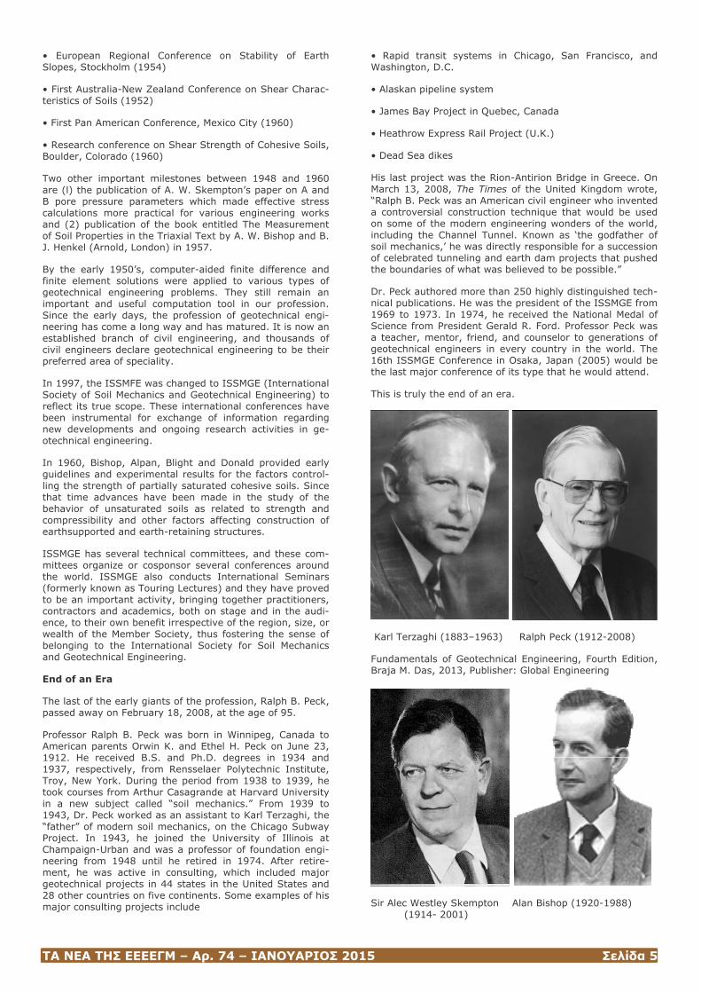
Karl Terzaghi (1883–1963) Ralph Peck (1912-2008)
Fundamentals of Geotechnical Engineering, Fourth Edition, Braja M. Das, 2013, Publisher: Global Engineering
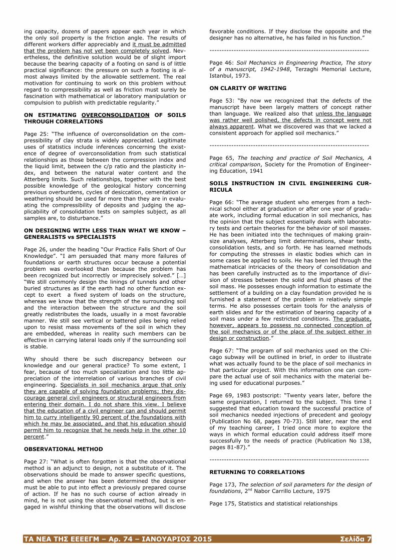
Sir Alec Westley Skempton Alan Bishop (1920-1988) (1914- 2001)
ΤΑ ΝΕΑ ΤΗΣ ΕΕΕΕΓΜ – Αρ. 74 – ΙΑΝΟΥΑΡΙΟΣ 2015 Σελίδα 6
ΑΡΘΡΑ
Επιλογές Αποσπασμάτων από τα βιβλία
Ralph Peck, Educator and Engineer: The Essence of the Man
Dunnicliff, J. and N. Peck Young, 2006, BiTech Publishers Ltd, Vancouver, BC, Canada
Judgement in Geotechnical Engineering, The Professional Legacy of Ralph Peck
Dunnicliff, J. and D.U. Deere, 1991, BiTech Publishers Ltd, Vancouver, BC, Canada
Μαρίνα Πανταζίδου Αναπληρώτρια Καθηγήτρια
Σχολή Πολιτικών Μηχανικών Ε.Μ.Π.
Ralph Peck – Educator & Engineer
SHEAR STRENGTH OF CLAYS
Page 125: The last sixty years (Proceedings 11th Int. Conf., San Francisco 1985).
Peck on Terzaghi’s conceptions of Soil Mechanics in 1925-1927 (page 126) – THE FIRST MODERN DECADE:
“He stressed soil classification, particularly in terms of physical properties that differentiate sands from clays, and at the same time attempted to identify unifying principles that could account for the properties of both materials. The strength of sands he recognized as purely frictional. He understood the influence of excess pore pressure on shear strength and recognized the need for performing drained shear tests to determine what we now call the effective shear strength. He regarded the shearing resistance of clays, which at the time he simply termed “cohesion”, as the product of capillary pressure and the tangent of the effective friction angle. Although conveniently measured as half the unconfined compressive strength, the “cohesion” of clays was thus no different in principle from the friction of sands. The large pore water tensions required to account for the high “cohesion” of some clays had, in Terzaghi’s words, “never been suspected up to this time”, and were not easily accepted by engineers who held the misconcep-tion that the tensile strength of water was limited to one atmosphere. The mechanism of shrinkage in clays, elegant-ly explained by capillarity, helped convince the doubters.
Terzaghi at this time emphasized three soil properties that he felt, when evaluated, would permit all practical problems of importance: the “cohesion” (and for sands the frictional resistance) as defined above; the “elastic” (actually the stress-deformation) properties; and the permeability. The phenomenon of consolidation was one manifestation of “elastic” properties.”
Page 130 STRENGTH OF SATURATED CLAYS – A CAPSULE REVIEW (1936-1961)
Hvorslev 1936 -what Terzaghi believed in 1939: shear strength of clays has two parts: one depending on effective stress, p’tanφο, considered to be effective friction, and one depending on void ratio, considered to be effective cohesion (although cohesion remains undefined!). The angle φο was determined from the inclination of failure planes in uncon-fined compression tests.
In the 40s the φ=0 concept prevails but cannot explain all observations.
Page 131: To reconcile matters, Terzaghi suggests that a clay is clay particles within silt assemblages: initially the gravity loads are carried by the silt particles. Further load-ing disturbs the silt assemblages and stresses are trans-ferred to the purely cohesive material, i.e. the clay.
Bishop provides theoretical justification and the limits of application of the φ=0 concept in 4 papers in the Rotter-dam conference (1948) – in one of them he describes the role of the compressibility (vertical) to the expansibility (lateral) in the pore pressures developed in a saturated clay in a triaxial test. Six years later (1954) he extends the the-ory to unsaturated materials (paper on A and B parameters in Geotechnique). However, in the States, engineers follow-ing Casagrande preferred to replicate loading and drainage conditions in the field, fit the data with an apparent angle of friction, and use this angle in the analysis (rather than fore-casting pore pressure values and carry explicit effective stress calculations).
In an attempt to reconcile these two camps, the ASCE Soils Division organized a Research Conference on Shear Strength of Cohesive Soils (Boulder, Colorado, June 1960).
Page 132: According to Peck, the conference “cleared the air enormously”, but he does not give any details or exam-ples. He then quotes Terzaghi who was unable to attend but read the papers and wrote a letter to the participants saying that: in the 1936 conference no one suspected how much more effort would be required to close the gaps in the understanding of the shear strength of clays… for 25 years many researchers on both sides of the Atlantic had tried to close the gaps… having read the papers, I see that a con-siderable amount of research is still required to close the gaps.
ON GEOTECHNICAL ENGINEERING and THE PREPA-RATION OF CIVIL ENGINEERS
Page 155: Geologan 1997. Our expanding industry: Tri-umphs and Perils (Geotechnical News 1997, 15-5, pg 3-7).
Page 157: “Geotechnics, more than most branches of engi-neering, observes and is guided by the results of its own activities. Many if not most of its projects are in at least some respect unique.”
Page 157: “…we may have forgotten that most civil engi-neering for our indispensable infrastructure is done by non-specialists who, at the least, may need to recognize when they are up against a problem requiring a specialist.” He goes on with describing a new faculty advertisement speci-fying advanced research specializations and also mention-ing that the successful applicant will also teach undergrad-uates. So Peck asks “teach what at the undergraduate lev-el?” “Where is the applicant who satisfies the requirements of the advertisement to learn such apparently mundane practical matters? [i.e. subjects taught to undergraduates] From teachers having the same research interests?”
Judgement in Geotechnical Engineering – The professional legacy of Ralph Peck
BEARING CAPACITY OF SANDS
Page 23: The direction of our profession, 8th Int. Conf. Mos-cow 1973, Presidential address
Page 24: “Consider, for example, the remarkable number of papers dealing with the ultimate bearing capacity of shallow footings on sands in terms of the angle of internal friction. Although a few workers have recognized the crucial role that the compressibility of sands plays in the ultimate bear-
ΤΑ ΝΕΑ ΤΗΣ ΕΕΕΕΓΜ – Αρ. 74 – ΙΑΝΟΥΑΡΙΟΣ 2015 Σελίδα 7
ing capacity, dozens of papers appear each year in which the only soil property is the friction angle. The results of different workers differ appreciably and it must be admitted that the problem has not yet been completely solved. Nev-ertheless, the definitive solution would be of slight import because the bearing capacity of a footing on sand is of little practical significance: the pressure on such a footing is al-most always limited by the allowable settlement. The real motivation for continuing to work on this problem without regard to compressibility as well as friction must surely be fascination with mathematical or laboratory manipulation or compulsion to publish with predictable regularity.”
ON ESTIMATING OVERCONSOLIDATION OF SOILS THROUGH CORRELATIONS
Page 25: “The influence of overconsolidation on the com-pressibility of clay strata is widely appreciated. Legitimate uses of statistics include inferences concerning the exist-ence of degree of overconsolidation from such statistical relationships as those between the compression index and the liquid limit, between the c/p ratio and the plasticity in-dex, and between the natural water content and the Atterberg limits. Such relationships, together with the best possible knowledge of the geological history concerning previous overburdens, cycles of desiccation, cementation or weathering should be used far more than they are in evalu-ating the compressibility of deposits and judging the ap-plicability of consolidation tests on samples subject, as all samples are, to disturbance.”
ON DESIGNING WITH LESS THAN WHAT WE KNOW – GENERALISTS vs SPECIALISTS
Page 26, under the heading “Our Practice Falls Short of Our Knowledge”. “I am persuaded that many more failures of foundations or earth structures occur because a potential problem was overlooked than because the problem has been recognized but incorrectly or imprecisely solved.” […] “We still commonly design the linings of tunnels and other buried structures as if the earth had no other function ex-cept to exert a fixed system of loads on the structure, whereas we know that the strength of the surrounding soil and the interaction between the structure and the soil greatly redistributes the loads, usually in a most favorable manner. We still see vertical or battered piles being relied upon to resist mass movements of the soil in which they are embedded, whereas in reality such members can be effective in carrying lateral loads only if the surrounding soil is stable.
Why should there be such discrepancy between our knowledge and our general practice? To some extent, I fear, because of too much specialization and too little ap-preciation of the interrelation of various branches of civil engineering. Specialists in soil mechanics argue that only they are capable of solving foundation problems; they dis-courage general civil engineers or structural engineers from entering their domain. I do not share this view. I believe that the education of a civil engineer can and should permit him to curry intelligently 90 percent of the foundations with which he may be associated, and that his education should permit him to recognize that he needs help in the other 10 percent.”
OBSERVATIONAL METHOD
Page 27: “What is often forgotten is that the observational method is an adjunct to design, not a substitute of it. The observations should be made to answer specific questions, and when the answer has been determined the designer must be able to put into effect a previously prepared course of action. If he has no such course of action already in mind, he is not using the observational method, but is en-gaged in wishful thinking that the observations will disclose
favorable conditions. If they disclose the opposite and the designer has no alternative, he has failed in his function.”
------------------------------------------------------------------
Page 46: Soil Mechanics in Engineering Practice, The story of a manuscript, 1942-1948, Terzaghi Memorial Lecture, Istanbul, 1973.
ON CLARITY OF WRITING
Page 53: “By now we recognized that the defects of the manuscript have been largely matters of concept rather than language. We realized also that unless the language was rather well polished, the defects in concept were not always apparent. What we discovered was that we lacked a consistent approach for applied soil mechanics.”
------------------------------------------------------------------
Page 65, The teaching and practice of Soil Mechanics, A critical comparison, Society for the Promotion of Engineer-ing Education, 1941
SOILS INSTRUCTION IN CIVIL ENGINEERING CUR-RICULA
Page 66: “The average student who emerges from a tech-nical school either at graduation or after one year of gradu-ate work, including formal education in soil mechanics, has the opinion that the subject essentially deals with laborato-ry tests and certain theories for the behavior of soil masses. He has been initiated into the techniques of making grain-size analyses, Atterberg limit determinations, shear tests, consolidation tests, and so forth. He has learned methods for computing the stresses in elastic bodies which can in some cases be applied to soils. He has been led through the mathematical intricacies of the theory of consolidation and has been carefully instructed as to the importance of divi-sion of stresses between the solid and fluid phases of the soil mass. He possesses enough information to estimate the settlement of a building on a clay foundation provided he is furnished a statement of the problem in relatively simple terms. He also possesses certain tools for the analysis of earth slides and for the estimation of bearing capacity of a soil mass under a few restricted conditions. The graduate, however, appears to possess no connected conception of the soil mechanics or of the place of the subject either in design or construction.”
Page 67: “The program of soil mechanics used on the Chi-cago subway will be outlined in brief, in order to illustrate what was actually found to be the place of soil mechanics in that particular project. With this information one can com-pare the actual use of soil mechanics with the material be-ing used for educational purposes.”
Page 69, 1983 postscript: “Twenty years later, before the same organization, I returned to the subject. This time I suggested that education toward the successful practice of soil mechanics needed injections of precedent and geology (Publication No 68, pages 70-73). Still later, near the end of my teaching career, I tried once more to explore the ways in which formal education could address itself more successfully to the needs of practice (Publication No 138, pages 81-87).”
------------------------------------------------------------------
RETURNING TO CORRELATIONS
Page 173, The selection of soil parameters for the design of foundations, 2nd Nabor Carrillo Lecture, 1975
Page 175, Statistics and statistical relationships

ΤΑ ΝΕΑ ΤΗΣ ΕΕΕΕΓΜ – Αρ. 74 – ΙΑΝΟΥΑΡΙΟΣ 2015 Σελίδα 8
“Statistical relations of purely empirical nature have been found over the years among various soil properties. Among these are the well-known relationships for clays:
Cc=0.009 (ωL-10)
between the compression index and the liquid limit;
su/p’=0.11 +0.0037Ip
between the ratio of the undrained shear strength to effec-tive normal pressure and the plasticity index; and
E=300 qu = 600 su
between Young’s modulus and the unconfined compressive strength or undrained shear strength. The limitations of these empirical relations are not always appreciated or even known. Nevertheless, the relations contain a substan-tial amount of our knowledge about soil properties and their interrelationships. In other words, they constitute extreme-ly condensed digests of a vast amount of information.”
------------------------------------------------------------------
Pages 201-204 Talk to the Society of American Military En-gineers, 1977.
ADVICE TO A YOUNG ENGINEER
Page 204, A set of four rules given by Terzaghi to his stu-dents at Harvard:
1. Engineering is a noble sport which calls for good sports-manship. Occasional blundering is part of the game. Let it be your ambition to be the first one to discover and an-nounce your blunders. If someone else gets ahead of you, take it with a smile and thank him for his interest. Once you begin to feel tempted to deny your blunders in the face of reasonable evidence you have ceased to be a good sport. You are already a crank or a grouch.
2. The worst habit you can possibly acquire is to become uncritical towards your own concepts and at the same time skeptical towards those of others. Once you arrive at that state you are in the grip of senility, regardless of your age.
3. When you commit one of your ideas to print, emphasize every controversial aspect of your thesis which you can perceive. Thus you win the respect of your readers and are kept aware of the possibilities for further improvement. A departure from this rule is the safest way to wreck your reputation and to paralyze your mental activities.
4. Very few people are so dumb or so dishonest that you could not learn anything from them.
ΤΑ ΝΕΑ ΤΗΣ ΕΕΕΕΓΜ – Αρ. 74 – ΙΑΝΟΥΑΡΙΟΣ 2015 Σελίδα 9
Geothermal Energy for Heating and Cooling: Full-Scale Testing and Numerical Modelling
Guillermo A Narsilio, Senior Lecturer, The University of Melbourne, Parkville, VIC 3010, Australia, email:
Ian W Johnston, Professor, The University of Melbourne, Parkville, VIC 3010, Australia, email:
Abstract
Ground-source heat pump (GSHP) systems efficiently heat and cool buildings using sustainable geothermal energy accessed via ground heat exchangers (GHEs). In closed loop systems, GHEs comprise pipes embedded in specifical-ly drilled boreholes or trenches or even built into founda-tions, all within a few tens of metres from the surface. In the State of Victoria in Australia, more than 85% of the electricity is generated from brown coal. Thus, given that GSHP systems operate at a coefficient of performance of about 4, the substitution of commonly used electrical heat-ing and cooling systems with geothermal systems could significantly reduce energy consumption and greenhouse gas emissions. This short article provides an overview of direct geothermal energy research and demonstration pro-jects undertaken by the University of Melbourne in Victoria and the parallel development of numerical models based on first principles. Implemented using finite element methods, the models enable detailed studies of GHEs. The 3D heat transfer process in short and long timescales can thus be investigated in detail to optimise the thermal performance of GHEs, and adapt design to local weather and ground conditions.
Keywords: Geothermal; Numerical Modelling; Ground Heat Exchanger; Design; Sustainability
1 Direct geothermal systems
The rate of growth of the human population and associated annual per capita energy consumption has been exponential ever since the industrial revolution (Glassley, 2010). Find-ing renewable energy sources with low greenhouse gas emissions has become imperative to help mitigating the environmental impacts of an ever-growing human presence on the planet. Geothermal energy is a versatile and near inexhaustible resource capable of satisfying these needs. Geothermal energy can be used for the provision of heat-ing, ventilation and air conditioning (HVAC) to residential, commercial and industrial buildings as well as for power generation (Glassley, 2010, Johnston et al., 2011).
Outside the volcanic regions of the world where it is readily available near the ground surface, geothermal energy can be accessed in two ways. One indirect form involves heat extracted using a fluid from boreholes drilled to several kilometres below the surface, where temperatures exceed 175ºC, to generate electricity with turbines. This source of power has enormous potential, but is still not producing electricity on a commercial scale. The other is the direct form, which is well established in parts of the world, but not yet widespread despite its relative simplicity.
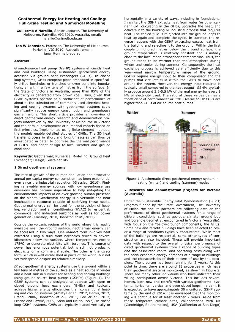
Direct geothermal energy systems use the ground within a few tens of metres of the surface as a heat source in winter and a heat sink in summer for heating and cooling buildings using ground-source heat pumps (GSHPs) (Figure 1). The GSHP systems can be designed to operate with open or closed ground heat exchangers (GHEs) and typically achieve higher energy efficiencies than conventional heat-ing and cooling systems (Amatya et al., 2012, Banks, 2012, Brandl, 2006, Johnston et al., 2011, Lee et al., 2012, Preene and Powrie, 2009, Stein and Meier, 1997). In closed loop GSHP systems, GHEs are typically placed vertically or
horizontally in a variety of ways, including in foundations. In winter, the GSHP extracts heat from water (or other car-rier fluid) circulating in the GHEs, upgrades the heat, and delivers it to the building or industrial process that requires heat. The cooled fluid is reinjected into the ground loops to heat up again and complete the cycle. In summer, the re-verse happens with the GSHP extracting excess heat from the building and rejecting it to the ground. Within the first couple of hundred metres below the ground surface, the ground temperature is relatively constant and is initially close to the local mean atmospheric temperature. Thus, the ground tends to be warmer than the atmosphere during winter and cooler during summer. Consequently, the heat exchange process is achieved very efficiently due to this year-round narrow temperature range of the ground. GSHPs require energy input to their compressor and the pumps that circulate fluid within the GHEs to move heat around the system. However, the energy input required is typically small compared to the heat output: GSHPs typical-ly produce around 3.5-5.5 kW of thermal energy for every 1 kW of electricity used. The ratio of these values defines a “coefficient of performance” or COP. Overall GSHP COPs are higher than COPs of air-source heat pumps.
Figure 1. A schematic direct geothermal energy system in heating (winter) and cooling (summer) modes
2 Research and demonstration projects for Victoria (Australia)
Under the Sustainable Energy Pilot Demonstration (SEPD) Program funded by the State Government, The University of Melbourne and its partners are collecting data on the performance of direct geothermal systems for a range of different conditions, such as geology, climate, ground loop and borehole geometry, encountered in Victoria (Australia), with focus on the “below-ground” components, the GHEs. Some new and retrofit buildings have been selected to cov-er a range of conditions typically encountered. While most of the buildings are residential, some other types of con-struction are also included. These will provide important data with respect to the overall physical performance of direct geothermal systems from a range of building types and the associated capital and operating costs along with the socio-economic energy demands of a range of buildings and the characteristics of their pattern of use by the occu-piers. The program has been running for 2 years. At this point in time, there are around 18 properties which have their geothermal systems monitored, as shown in Figure 2. There are many other individuals who have indicated their willing participation across Victoria. This includes several homes, both new and retrofit with various geothermal sys-tems: horizontal, vertical and even closed loops in a dam. It is expected to have approximately 30 monitored GSHP sys-tems by the end of 2014. It is envisaged that the monitor-ing will continue for at least another 2 years. Aside from these temperate climate sites, collaborations with UK (Cambridge, Southampton), USA (Californian at San Diego)
ΤΑ ΝΕΑ ΤΗΣ ΕΕΕΕΓΜ – Αρ. 74 – ΙΑΝΟΥΑΡΙΟΣ 2015 Σελίδα 10
and Korea (Korea U., KAIST) will bring experimental data from sites of different climates.
Figure 2. Map of Melbourne and surroundings (Victoria, Australia) showing locations (solid circles) where individual full scale geothermal projects are being instrumented and
monitored to date (September 2014)
These current multi-instrumented field facilities are unique in Australia and, overall, believed to be the largest field instrumented exercise in direct geothermal research in the world. The analysis of these experimental data will be used to advance design guidelines for GHEs.
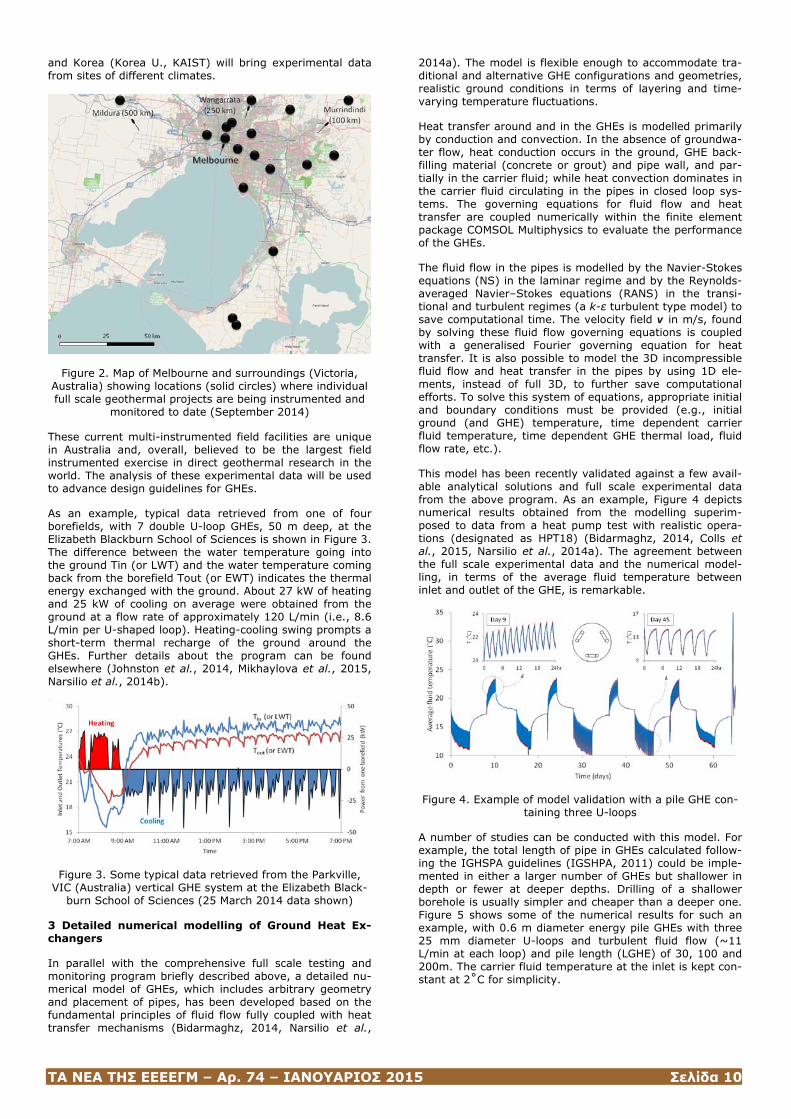
As an example, typical data retrieved from one of four borefields, with 7 double U-loop GHEs, 50 m deep, at the Elizabeth Blackburn School of Sciences is shown in Figure 3. The difference between the water temperature going into the ground Tin (or LWT) and the water temperature coming back from the borefield Tout (or EWT) indicates the thermal energy exchanged with the ground. About 27 kW of heating and 25 kW of cooling on average were obtained from the ground at a flow rate of approximately 120 L/min (i.e., 8.6 L/min per U-shaped loop). Heating-cooling swing prompts a short-term thermal recharge of the ground around the GHEs. Further details about the program can be found elsewhere (Johnston et al., 2014, Mikhaylova et al., 2015, Narsilio et al., 2014b).
Figure 3. Some typical data retrieved from the Parkville, VIC (Australia) vertical GHE system at the Elizabeth Black-
burn School of Sciences (25 March 2014 data shown)
3 Detailed numerical modelling of Ground Heat Ex-changers
In parallel with the comprehensive full scale testing and monitoring program briefly described above, a detailed nu-merical model of GHEs, which includes arbitrary geometry and placement of pipes, has been developed based on the fundamental principles of fluid flow fully coupled with heat transfer mechanisms (Bidarmaghz, 2014, Narsilio et al.,
2014a). The model is flexible enough to accommodate tra-ditional and alternative GHE configurations and geometries, realistic ground conditions in terms of layering and time-varying temperature fluctuations.
Heat transfer around and in the GHEs is modelled primarily by conduction and convection. In the absence of groundwa-ter flow, heat conduction occurs in the ground, GHE back-filling material (concrete or grout) and pipe wall, and par-tially in the carrier fluid; while heat convection dominates in the carrier fluid circulating in the pipes in closed loop sys-tems. The governing equations for fluid flow and heat transfer are coupled numerically within the finite element package COMSOL Multiphysics to evaluate the performance of the GHEs.
The fluid flow in the pipes is modelled by the Navier-Stokes equations (NS) in the laminar regime and by the Reynolds-averaged Navier–Stokes equations (RANS) in the transi-tional and turbulent regimes (a k-ε turbulent type model) to save computational time. The velocity field v in m/s, found by solving these fluid flow governing equations is coupled with a generalised Fourier governing equation for heat transfer. It is also possible to model the 3D incompressible fluid flow and heat transfer in the pipes by using 1D ele-ments, instead of full 3D, to further save computational efforts. To solve this system of equations, appropriate initial and boundary conditions must be provided (e.g., initial ground (and GHE) temperature, time dependent carrier fluid temperature, time dependent GHE thermal load, fluid flow rate, etc.).
This model has been recently validated against a few avail-able analytical solutions and full scale experimental data from the above program. As an example, Figure 4 depicts numerical results obtained from the modelling superim-posed to data from a heat pump test with realistic opera-tions (designated as HPT18) (Bidarmaghz, 2014, Colls et al., 2015, Narsilio et al., 2014a). The agreement between the full scale experimental data and the numerical model-ling, in terms of the average fluid temperature between inlet and outlet of the GHE, is remarkable.
Figure 4. Example of model validation with a pile GHE con-taining three U-loops
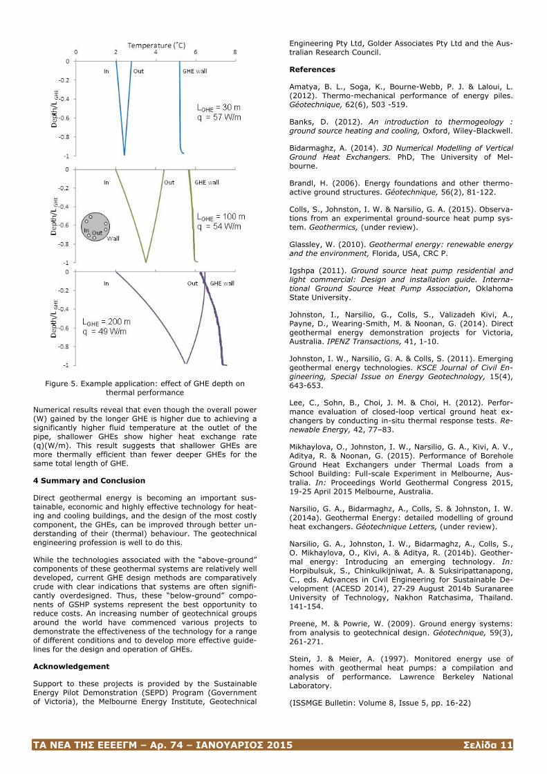
A number of studies can be conducted with this model. For example, the total length of pipe in GHEs calculated follow-ing the IGHSPA guidelines (IGSHPA, 2011) could be imple-mented in either a larger number of GHEs but shallower in depth or fewer at deeper depths. Drilling of a shallower borehole is usually simpler and cheaper than a deeper one. Figure 5 shows some of the numerical results for such an example, with 0.6 m diameter energy pile GHEs with three 25 mm diameter U-loops and turbulent fluid flow (~11 L/min at each loop) and pile length (LGHE) of 30, 100 and 200m. The carrier fluid temperature at the inlet is kept con-stant at 2˚C for simplicity.
ΤΑ ΝΕΑ ΤΗΣ ΕΕΕΕΓΜ – Αρ. 74 – ΙΑΝΟΥΑΡΙΟΣ 2015 Σελίδα 11
Figure 5. Example application: effect of GHE depth on thermal performance
Numerical results reveal that even though the overall power (W) gained by the longer GHE is higher due to achieving a significantly higher fluid temperature at the outlet of the pipe, shallower GHEs show higher heat exchange rate (q)(W/m). This result suggests that shallower GHEs are more thermally efficient than fewer deeper GHEs for the same total length of GHE.
4 Summary and Conclusion
Direct geothermal energy is becoming an important sus-tainable, economic and highly effective technology for heat-ing and cooling buildings, and the design of the most costly component, the GHEs, can be improved through better un-derstanding of their (thermal) behaviour. The geotechnical engineering profession is well to do this.
While the technologies associated with the “above-ground” components of these geothermal systems are relatively well developed, current GHE design methods are comparatively crude with clear indications that systems are often signifi-cantly overdesigned. Thus, these “below-ground” compo-nents of GSHP systems represent the best opportunity to reduce costs. An increasing number of geotechnical groups around the world have commenced various projects to demonstrate the effectiveness of the technology for a range of different conditions and to develop more effective guide-lines for the design and operation of GHEs.
Acknowledgement
Support to these projects is provided by the Sustainable Energy Pilot Demonstration (SEPD) Program (Government of Victoria), the Melbourne Energy Institute, Geotechnical
Engineering Pty Ltd, Golder Associates Pty Ltd and the Aus-tralian Research Council.
References
Amatya, B. L., Soga, K., Bourne-Webb, P. J. & Laloui, L. (2012). Thermo-mechanical performance of energy piles. Géotechnique, 62(6), 503 -519.
Banks, D. (2012). An introduction to thermogeology : ground source heating and cooling, Oxford, Wiley-Blackwell.
Bidarmaghz, A. (2014). 3D Numerical Modelling of Vertical Ground Heat Exchangers. PhD, The University of Mel-bourne.
Brandl, H. (2006). Energy foundations and other thermo-active ground structures. Géotechnique, 56(2), 81-122.
Colls, S., Johnston, I. W. & Narsilio, G. A. (2015). Observa-tions from an experimental ground-source heat pump sys-tem. Geothermics, (under review).
Glassley, W. (2010). Geothermal energy: renewable energy and the environment, Florida, USA, CRC P.
Igshpa (2011). Ground source heat pump residential and light commercial: Design and installation guide. Interna-tional Ground Source Heat Pump Association, Oklahoma State University.
Johnston, I., Narsilio, G., Colls, S., Valizadeh Kivi, A., Payne, D., Wearing-Smith, M. & Noonan, G. (2014). Direct geothermal energy demonstration projects for Victoria, Australia. IPENZ Transactions, 41, 1-10.
Johnston, I. W., Narsilio, G. A. & Colls, S. (2011). Emerging geothermal energy technologies. KSCE Journal of Civil En-gineering, Special Issue on Energy Geotechnology, 15(4), 643-653.
Lee, C., Sohn, B., Choi, J. M. & Choi, H. (2012). Perfor-mance evaluation of closed-loop vertical ground heat ex-changers by conducting in-situ thermal response tests. Re-newable Energy, 42, 77–83.
Mikhaylova, O., Johnston, I. W., Narsilio, G. A., Kivi, A. V., Aditya, R. & Noonan, G. (2015). Performance of Borehole Ground Heat Exchangers under Thermal Loads from a School Building: Full-scale Experiment in Melbourne, Aus-tralia. In: Proceedings World Geothermal Congress 2015, 19-25 April 2015 Melbourne, Australia.
Narsilio, G. A., Bidarmaghz, A., Colls, S. & Johnston, I. W. (2014a). Geothermal Energy: detailed modelling of ground heat exchangers. Géotechnique Letters, (under review).
Narsilio, G. A., Johnston, I. W., Bidarmaghz, A., Colls, S., O. Mikhaylova, O., Kivi, A. & Aditya, R. (2014b). Geother-mal energy: Introducing an emerging technology. In: Horpibulsuk, S., Chinkulkijniwat, A. & Suksiripattanapong, C., eds. Advances in Civil Engineering for Sustainable De-velopment (ACESD 2014), 27-29 August 2014b Suranaree University of Technology, Nakhon Ratchasima, Thailand. 141-154.
Preene, M. & Powrie, W. (2009). Ground energy systems: from analysis to geotechnical design. Géotechnique, 59(3), 261-271.
Stein, J. & Meier, A. (1997). Monitored energy use of homes with geothermal heat pumps: a compilation and analysis of performance. Lawrence Berkeley National Laboratory.
(ISSMGE Bulletin: Volume 8, Issue 5, pp. 16-22)
ΤΑ ΝΕΑ ΤΗΣ ΕΕΕΕΓΜ – Αρ. 74 – ΙΑΝΟΥΑΡΙΟΣ 2015 Σελίδα 12
Design and Construction of A Cement Stabi-lised-Shored Reinforced Soil Wall
D.A.F. Oliveira1, F. Badelow2, P.K. Wong2 and D. Gor-man3
1Associate Geomechanics Engineer, Coffey, Perth and Re-search Fellow, University of Wollongong, Australia, 2Senior Principal Geotechnical Engineer, Coffey, Sydney, Australia, 3Geotechnical Engineer, Coffey, Sydney, Australia
ABSTRACT
This paper presents the design approach, methods of anal-ysis, material testing and construction of a Cement Stabi-lised-Shored reinforced soil wall (RSW) for Hills M2 Upgrade project in Sydney, NSW. Particular attention was given to the deformation modulus of the backfill material and stress conditions within the RSW that could promote cracking.
1 Introduction
The NSW Government announced the approval of the Hills M2 Upgrade on Tuesday, 26 October 2010. The Hills M2 Upgrade widens the existing motorway generally between Windsor Road, Baulkham Hills and Lane Cove Road, North Ryde including delivery of four new ramps to improve ac-cess to the motorway.
The Hills M2 Motorway plays a key role in Sydney's Orbital network linking the north west region to the lower north shore and Sydney's CBD. It is a key road freight and com-muter route and connects the major employment hubs of Macquarie Park and Norwest Business Park. Construction began in January 2011 and is completion is estimated for early August 2013.
Due to site constraints (e.g. existing sedimentation basins, driveways, boundary restrictions etc.), there were a num-ber of locations throughout the Hills M2 Upgrade project alignment where limited space was available for the exten-sion of the existing relatively high retaining walls which, in most cases, were reinforced soil walls (RSW).
Construction of RSWs is often the preferred retention solu-tion in road works as it involves a fill strengthening process that is considered very cost effective. The current industry practice typically adopts a minimum RSW reinforcement length (L) equivalent to approximately seventy percent of the design height (H) of the wall, i.e. L = 0.7H. However, at some locations along the Hills M2 Motorway, the use of conventional RSWs was not feasible as the available space was limited to only 0.3H to 0.5H. In addition, the transfer or application of new loads to the existing Hills M2 RSWs was considered to be of high risk as movement of these RSWs had been observed under current loading.
Constructability issues were also identified in relation to the other solutions. For instance, one of the concept designs considered a hybrid retaining wall where the upper section of the wall consisted of a RSW limited to 8 m in height and a lower section comprising anchored precast panels. The total height of this hybrid wall was limited to 17 m. The limited available width resulted in anchors inclined at 45º or steeper in order to avoid cutting the geosynthetic rein-forcement within the existing RSWs which had web type layout (Paraweb). As a result of the steep anchor inclination a structural facing would be required to accommodate the large vertical loads applied by the anchors, comprising pre-cast concrete columns with plan dimensions of 1.2 m x 1.0 m and spaced at 3 m centres. It was also initially anticipat-ed that the lower layers of steel reinforcement within the proposed upper RSW would be connected to the facing panels of the existing RSWs. However, during Detailed De-
sign phase (DD), the design team raised concerns about the integrity of the existing RSW as significant movement of these RSWs had been observed. In addition, the construc-tion team also identified difficulties in relation to the instal-lation of the proposed steeply inclined anchors.
As a result, an alternative solution was required and a de-sign procedure was developed that could consider the stabi-lising effect of the existing RSW with regard to the reduc-tion of lateral loads acting on the new RSW. Under such conditions, Berg et al. (2009) presented two design ap-proaches for RSW:
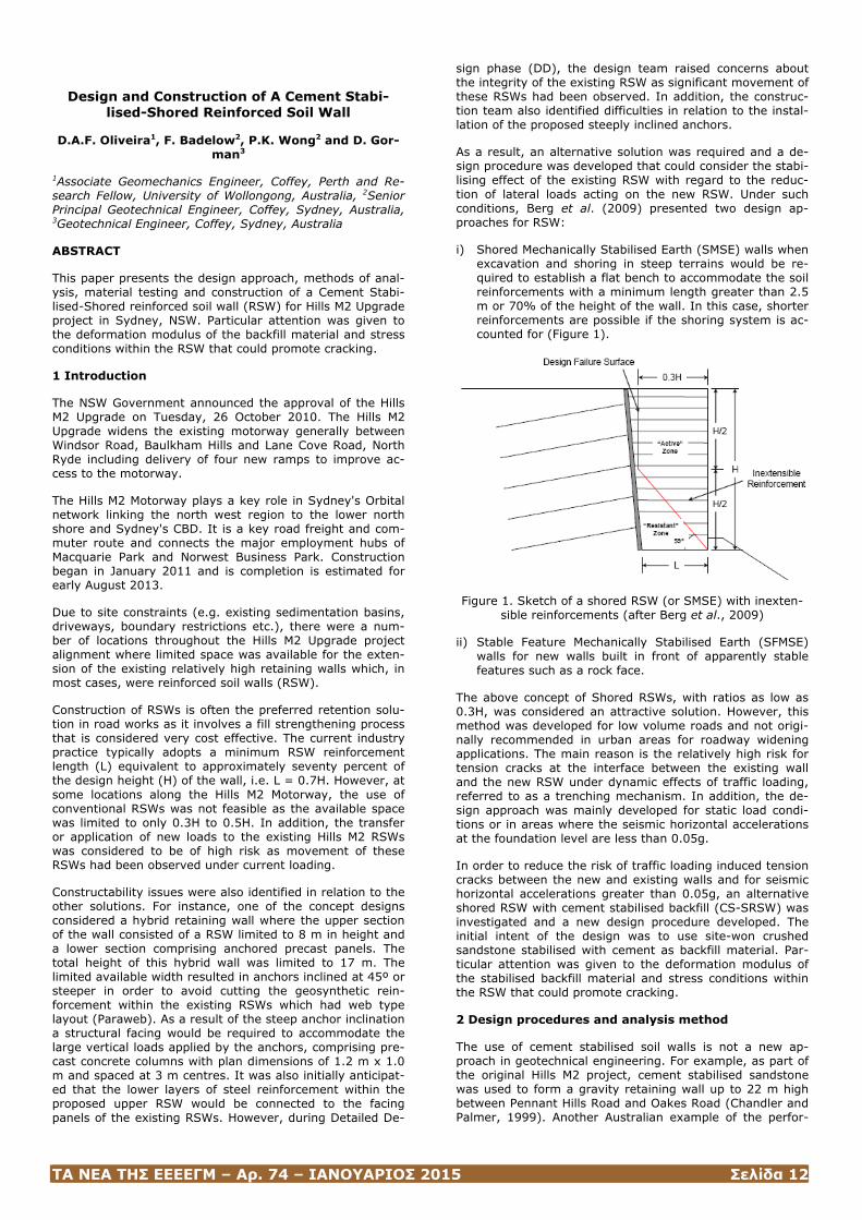
i) Shored Mechanically Stabilised Earth (SMSE) walls when excavation and shoring in steep terrains would be re-quired to establish a flat bench to accommodate the soil reinforcements with a minimum length greater than 2.5 m or 70% of the height of the wall. In this case, shorter reinforcements are possible if the shoring system is ac-counted for (Figure 1).
Figure 1. Sketch of a shored RSW (or SMSE) with inexten-sible reinforcements (after Berg et al., 2009)
ii) Stable Feature Mechanically Stabilised Earth (SFMSE) walls for new walls built in front of apparently stable features such as a rock face.
The above concept of Shored RSWs, with ratios as low as 0.3H, was considered an attractive solution. However, this method was developed for low volume roads and not origi-nally recommended in urban areas for roadway widening applications. The main reason is the relatively high risk for tension cracks at the interface between the existing wall and the new RSW under dynamic effects of traffic loading, referred to as a trenching mechanism. In addition, the de-sign approach was mainly developed for static load condi-tions or in areas where the seismic horizontal accelerations at the foundation level are less than 0.05g.
In order to reduce the risk of traffic loading induced tension cracks between the new and existing walls and for seismic horizontal accelerations greater than 0.05g, an alternative shored RSW with cement stabilised backfill (CS-SRSW) was investigated and a new design procedure developed. The initial intent of the design was to use site-won crushed sandstone stabilised with cement as backfill material. Par-ticular attention was given to the deformation modulus of the stabilised backfill material and stress conditions within the RSW that could promote cracking.
2 Design procedures and analysis method
The use of cement stabilised soil walls is not a new ap-proach in geotechnical engineering. For example, as part of the original Hills M2 project, cement stabilised sandstone was used to form a gravity retaining wall up to 22 m high between Pennant Hills Road and Oakes Road (Chandler and Palmer, 1999). Another Australian example of the perfor-
ΤΑ ΝΕΑ ΤΗΣ ΕΕΕΕΓΜ – Αρ. 74 – ΙΑΝΟΥΑΡΙΟΣ 2015 Σελίδα 13
mance of a retaining wall with cement stabilised soil is pre-sented by Ismail (2005). However, the key differentiator and innovation of the current application is perhaps the slenderness of the designed walls, with width to height rati-os of less than 0.4, and the combination with soil rein-forcement techniques. Several challenges, as described below had to be overcome before acceptance of this inno-vative design.
Perhaps, the first question to be addressed by the design approach is the assumed behaviour of the wall: flexible or rigid-monolithic? Conventional RSW are considered to be flexible, which would be even more pronounced at L/H < 0.4. However, the cement stabilisation will play a role in the deformational behaviour of the backfill, and, in fact, that was the main objective of the stabilisation, i.e. to address the “trenching mechanism” of the original SMSE concept.
As a starting point it was considered that the CS-SRSW could behave as a monolithic gravity wall due to the rela-tively high modulus of elasticity (E >1000 MPa) targeted for the stabilised fill even at low cement content (4% to 5%). This assumption was also based on similarities with the design of retaining walls with cement stabilized soil and RSW concrete panels as reported by Derek and Crockford (1991). In their design, the main objective of the rein-forcement was to hold up the concrete panels, therefore enabling the use of shorter reinforcement length than typi-cal RSW as it was not considered for internal stability. Derek and Crockford (1991) study included numerical anal-yses, physical modelling by centrifuge testing and a full scale of trial wall up to 7 m high and 200 m long.
Despite the assumption of a rigid-monolithic behaviour, cracking of the stabilised material was a concern during the design phase. In order to reduce the potential for cracking initiation under design loading conditions, the design proce-dure aimed to control the stresses within the stabi-lised soil mass to within the lower range of the elastic be-haviour of the stabilised material. This was initially based on the con-cept of cracking initiation of intact rock samples in laborato-ry testing. In addition, according to DoT (1986), if a ce-mented material is subjected to repetitive (dynamic) load-ing within its elastic range and is not loaded beyond the stress at which microcracking begins, then the material will likely remain intact for an indefinite period. It is also stated in DoT (1986) that, based on laboratory tests on cement stabilised materials, microcracking apparently only initiates for stresses beyond approximately 35% of the unconfined compressive strength (UCS) of the material. Cracking due to drying shrinkage and thermal effects were also consid-ered limited due to both low cement content and low water content for the stabilised material, with cement contents targeted at 4% to 5%.
However, it was also recognised that there could still be potential for cracking to occur in the long term, particularly if associated with material degradation and changes in moisture content and considering an intentional conserva-tive approach. As a result, a second design approach was considered where the cement stabilised mass was assumed to be fully cracked, thus, behaving like a blocky medium with more similarities to a flexible RSW where the soil rein-forcement plays a more significant role.
For both approaches discussed above, the following loading conditions were assumed: (a) live (traffic) load of 20 kPa acting on the wall; (b) horizontal seismic acceleration coef-ficient kh = 0.14; (c) vertical seismic acceleration coeffi-cient kv = 0.07; and (d) maximum impact load I = 17 kN/m on the traffic barrier located on top of the CS-SRSW.
A minimum factor of safety (FS) of 2 under static loading and a FS of 1.2 under seismic loading were targeted for all mechanisms under analyses, except for bearing capacity where a minimum FS of 3.0 was targeted. In general, the
proposed CS-SRSWs were to be constructed on a concrete platform founded on Class IV Sandstone (rock class as de-fined by Pells et al, 1998) or better.
2.1 Cement stabilised backfill substance parameters
During the design stage and before any laboratory test had been carried out, a cement content between 4% and 5% was assumed for the stabilised material. This value was based on the results reported by Chandler and Palmer (1999) which showed UCS values of 4.3 to 8.4 MPa for cored samples taken during construction of the cement stabilised wall of the original Hills M2 construction with a cement content of 4.5%. Chandler and Palmer (1999) also reported UCS values of 3 MPa for laboratory results on samples compacted at 98% of the standard maximum dry density within ±2% of the optimum moisture content.
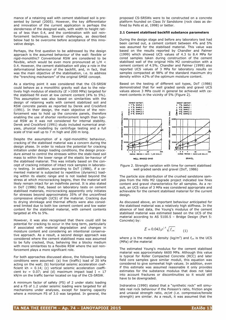
Based on the testing of different soil types, DoT (1986) demonstrated that for well graded sands and gravel UCS values above 3 MPa could in general be achieved with ce-ment contents in the vicinity of 5% (Figure 2).
Figure 2. Strength variation with time for cement stabilised well graded sands and gravel (DoT, 1986)
The particle size distribution of the crushed sandstone sam-ples from the Hills M2 Upgrade project indicated low fines content and gravel characteristics for all samples. As a re-sult, an UCS value of 3 MPa was considered appropriate and achievable for the cement stabilised material for the current design.
As discussed above, an important behaviour anticipated for the stabilised material was a relatively high stiffness. In the absence of test data, the Young’s modulus of the cement stabilised material was estimated based on the UCS of the material according to AS 5100.5 – Bridge Design (Part 5: Concrete) by:
(1)
where ρ is the material density (kg/m3) and fcm is the UCS (MPa) of the material
The estimated Young’s modulus for the cement stabilised material was approximately 6600 MPa. Although this value is typical for Roller Compacted Concrete (RCC) and later field core samples gave similar moduli, this equation was considered to give somewhat high values. In addition, even if this estimate was assumed reasonable it only provides estimates for the substance modulus that does not take into account fractures or discontinuities so it would still have to be downgraded.
Indraratna (1990) stated that a “synthetic rock” will simu-late real rock behaviour if the Poisson’s ratio, friction angle and uniaxial strength ratio, σc/σt (i.e. compressive/tensile strength) are similar. As a result, it was assumed that the
ΤΑ ΝΕΑ ΤΗΣ ΕΕΕΕΓΜ – Αρ. 74 – ΙΑΝΟΥΑΡΙΟΣ 2015 Σελίδα 14
cement stabilised sandstone would present similar behav-iour to that of a weathered sandstone rock. An alternative approach, based on rock mechanics correlations was then adopted (Deere, 1968):
Ε = MR x UCS (2)
where MR is the modulus ratio, typically varying from 200 to 1000 and UCS is uniaxial compressive strength (MPa). A modulus ratio MR of 350, typical for sandstone, was adopt-ed for the cement stabilised material which is somewhat lower than the value adopted by Chandler and Palmer (1999) for the existing Hills M2 cement stabilised wall. The adopted modulus ratio seems to yield consistent values with those obtained by Derek and Crockford (1991) of up to 875 MPa for a cement stabilised sand with 7% cement con-tent.
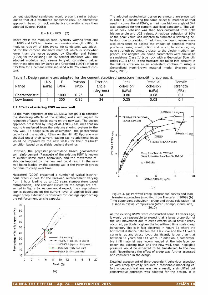
The adopted geotechnical design parameters are presented in Table 1. Considering the same select fill material as that used in conventional RSWs, a minimum friction angle of 34º was assumed for the cement stabilised sandstone. The val-ue of peak cohesion was then back-calculated from both friction angle and UCS values. A residual cohesion of 10% of the peak value was adopted to simulate a softening be-haviour due to cracking. In addition, low bound values were also considered to assess the impact of potential mixing problems during construction and which, to some degree, gave strength parameters closer to the blocky medium ap-proach. The adopted low bound parameters were similar to a sandstone Class IV type rock with a Geological Strength Index (GSI) of 45, if the fractures are taken into account in the failure criterion as an equivalent continuum using a Generalised Hoek-Brown material model (Marinos and Hoek, 2000).
2.2 Effects of existing RSW on new wall
As the main objective of the CS-SRSW design is to consider the stabilising effects of the existing walls with regard to reduction of lateral loads acting on the new wall. The design approach presented by Berg et al. (2009) assumes that no load is transferred from the existing shoring system to the new wall. To adopt such an assumption, the geotechnical capacity of the existing RSWs on the Hill M2 Upgrade was checked under their current loading (as no additional loads would be imposed by the new walls) for their "as-built" condition based on available designs drawings.
However, the polyester-polyethylene based geosynthetic soil reinforcement (Paraweb) of the existing RSW is known to exhibit some creep behaviour, and the movement re-striction imposed by the new wall could result in the new wall being loaded by the existing wall if the Paraweb straps continue to creep over time.
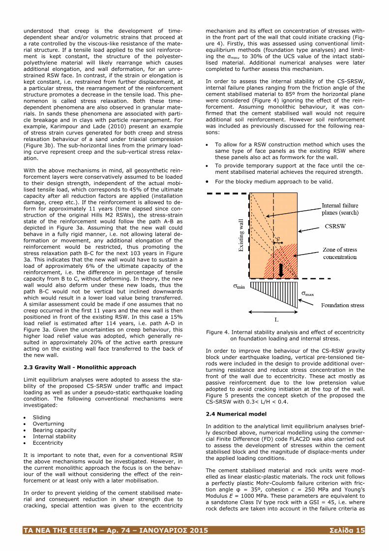
Maccaferri (2009) presented a number of typical isochro-nous creep curves for the Paraweb reinforcement varying from 1 hour loading up to 120 years (temperature based extrapolation). The relevant curves for the design are pre-sented in Figure 3a. As one would expect, the creep behav-iour is dependent on the current level of applied load and larger creep extension is observed for loadings approaching the reinforcement tensile capacity.
(a)
(b)
Figure 3. (a) Paraweb creep isochronous curves and load transfer approaches (modified from Maccaferri, 2009) (b)
Time dependent behaviour - creep and stress relaxation - of a sand in triaxial compression (after Karimpour and Lade,
2010)
As the existing RSWs were constructed some 13 years ago, it would be reasonable to expect that a large proportion of the wall movement due to creep effects would have already occurred, particularly given the logarithmic time scale creep behaviour. This is in fact observed in Figure 3a where the horizontal distance between the 1 h curve and the 11 years curve is, at any stress level, significantly larger than that between 11 years and 114 years. In addition, a compressi-ble infill material was recommended at the interface be-tween the existing RSW and the new wall, thus, negligible pressure would be expected to be transferred to the new wall. Nevertheless the effect of creep was further assessed and considered in the design.
Detailed assessment of time-dependent behaviour associat-ed with creep typically requires a reasonable modelling ef-fort in geotechnical analyses. As a result, a simplified but conservative approach was adopted for the design. It is
ΤΑ ΝΕΑ ΤΗΣ ΕΕΕΕΓΜ – Αρ. 74 – ΙΑΝΟΥΑΡΙΟΣ 2015 Σελίδα 15
understood that creep is the development of time-dependent shear and/or volumetric strains that proceed at a rate controlled by the viscous-like resistance of the mate-rial structure. If a tensile load applied to the soil reinforce-ment is kept constant, the structure of the polyester-polyethylene material will likely rearrange which causes additional elongation, and wall deformation, for an unre-strained RSW face. In contrast, if the strain or elongation is kept constant, i.e. restrained from further displacement, at a particular stress, the rearrangement of the reinforcement structure promotes a decrease in the tensile load. This phe-nomenon is called stress relaxation. Both these time-dependent phenomena are also observed in granular mate-rials. In sands these phenomena are associated with parti-cle breakage and in clays with particle rearrangement. For example, Karimpour and Lade (2010) present an example of stress strain curves generated for both creep and stress relaxation behaviour of a sand under triaxial compression (Figure 3b). The sub-horizontal lines from the primary load-ing curve represent creep and the sub-vertical stress relax-ation.
With the above mechanisms in mind, all geosynthetic rein-forcement layers were conservatively assumed to be loaded to their design strength, independent of the actual mobi-lised tensile load, which corresponds to 45% of the ultimate capacity after all reduction factors are applied (installation damage, creep etc.). If the reinforcement is allowed to de-form for approximately 11 years (time elapsed since con-struction of the original Hills M2 RSWs), the stress-strain state of the reinforcement would follow the path A-B as depicted in Figure 3a. Assuming that the new wall could behave in a fully rigid manner, i.e. not allowing lateral de-formation or movement, any additional elongation of the reinforcement would be restricted, thus promoting the stress relaxation path B-C for the next 103 years in Figure 3a. This indicates that the new wall would have to sustain a load of approximately 6% of the ultimate capacity of the reinforcement, i.e. the difference in percentage of tensile capacity from B to C, without deforming. In theory, the new wall would also deform under these new loads, thus the path B-C would not be vertical but inclined downwards which would result in a lower load value being transferred. A similar assessment could be made if one assumes that no creep occurred in the first 11 years and the new wall is then positioned in front of the existing RSW. In this case a 15% load relief is estimated after 114 years, i.e. path A-D in Figure 3a. Given the uncertainties on creep behaviour, this higher load relief value was adopted, which generally re-sulted in approximately 20% of the active earth pressure acting on the existing wall face transferred to the back of the new wall.
2.3 Gravity Wall - Monolithic approach
Limit equilibrium analyses were adopted to assess the sta-bility of the proposed CS-SRSW under traffic and impact loading as well as under a pseudo-static earthquake loading condition. The following conventional mechanisms were investigated:
• Sliding • Overturning • Bearing capacity • Internal stability • Eccentricity
It is important to note that, even for a conventional RSW the above mechanisms would be investigated. However, in the current monolithic approach the focus is on the behav-iour of the wall without considering the effect of the rein-forcement or at least only with a later mobilisation.
In order to prevent yielding of the cement stabilised mate-rial and consequent reduction in shear strength due to cracking, special attention was given to the eccentricity
mechanism and its effect on concentration of stresses with-in the front part of the wall that could initiate cracking (Fig-ure 4). Firstly, this was assessed using conventional limit-equilibrium methods (foundation type analyses) and limit-ing the σmax, to 30% of the UCS value of the intact stabi-lised material. Additional numerical analyses were later completed to further assess this mechanism.
In order to assess the internal stability of the CS-SRSW, internal failure planes ranging from the friction angle of the cement stabilised material to 85º from the horizontal plane were considered (Figure 4) ignoring the effect of the rein-forcement. Assuming monolithic behaviour, it was con-firmed that the cement stabilised wall would not require additional soil reinforcement. However soil reinforcement was included as previously discussed for the following rea-sons:
• To allow for a RSW construction method which uses the same type of face panels as the existing RSW where these panels also act as formwork for the wall.
• To provide temporary support at the face until the ce-ment stabilised material achieves the required strength.
• For the blocky medium approach to be valid.
Figure 4. Internal stability analysis and effect of eccentricity on foundation loading and internal stress.
In order to improve the behaviour of the CS-RSW gravity block under earthquake loading, vertical pre-tensioned tie-rods were included in the design to provide additional over-turning resistance and reduce stress concentration in the front of the wall due to eccentricity. These act mostly as passive reinforcement due to the low pretension value adopted to avoid cracking initiation at the top of the wall. Figure 5 presents the concept sketch of the proposed the CS-SRSW with 0.3< L/H < 0.4.
2.4 Numerical model
In addition to the analytical limit equilibrium analyses brief-ly described above, numerical modelling using the commer-cial Finite Difference (FD) code FLAC2D was also carried out to assess the development of stresses within the cement stabilised block and the magnitude of displace-ments under the applied loading conditions.
The cement stabilised material and rock units were mod-elled as linear elastic-plastic materials. The rock unit follows a perfectly plastic Mohr-Coulomb failure criterion with fric-tion angle φ = 35º, cohesion c = 250 MPa and Young’s Modulus E = 1000 MPa. These parameters are equivalent to a sandstone Class IV type rock with a GSI = 45, i.e. where rock defects are taken into account in the failure criteria as
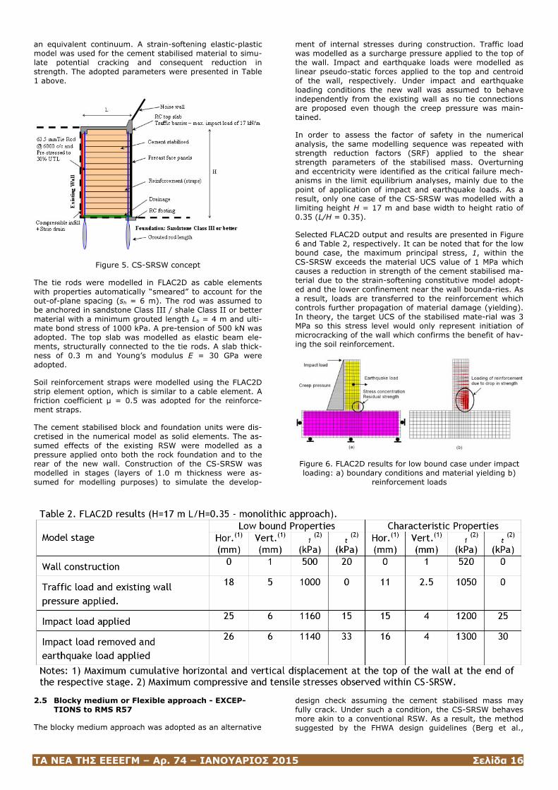
ΤΑ ΝΕΑ ΤΗΣ ΕΕΕΕΓΜ – Αρ. 74 – ΙΑΝΟΥΑΡΙΟΣ 2015 Σελίδα 16
an equivalent continuum. A strain-softening elastic-plastic model was used for the cement stabilised material to simu-late potential cracking and consequent reduction in strength. The adopted parameters were presented in Table 1 above.
Figure 5. CS-SRSW concept
The tie rods were modelled in FLAC2D as cable elements with properties automatically “smeared” to account for the out-of-plane spacing (sh = 6 m). The rod was assumed to be anchored in sandstone Class III / shale Class II or better material with a minimum grouted length Lb = 4 m and ulti-mate bond stress of 1000 kPa. A pre-tension of 500 kN was adopted. The top slab was modelled as elastic beam ele-ments, structurally connected to the tie rods. A slab thick-ness of 0.3 m and Young’s modulus E = 30 GPa were adopted.
Soil reinforcement straps were modelled using the FLAC2D strip element option, which is similar to a cable element. A friction coefficient μ = 0.5 was adopted for the reinforce-ment straps.
The cement stabilised block and foundation units were dis-cretised in the numerical model as solid elements. The as-sumed effects of the existing RSW were modelled as a pressure applied onto both the rock foundation and to the rear of the new wall. Construction of the CS-SRSW was modelled in stages (layers of 1.0 m thickness were as-sumed for modelling purposes) to simulate the develop-
ment of internal stresses during construction. Traffic load was modelled as a surcharge pressure applied to the top of the wall. Impact and earthquake loads were modelled as linear pseudo-static forces applied to the top and centroid of the wall, respectively. Under impact and earthquake loading conditions the new wall was assumed to behave independently from the existing wall as no tie connections are proposed even though the creep pressure was main-tained.
In order to assess the factor of safety in the numerical analysis, the same modelling sequence was repeated with strength reduction factors (SRF) applied to the shear strength parameters of the stabilised mass. Overturning and eccentricity were identified as the critical failure mech-anisms in the limit equilibrium analyses, mainly due to the point of application of impact and earthquake loads. As a result, only one case of the CS-SRSW was modelled with a limiting height H = 17 m and base width to height ratio of 0.35 (L/H = 0.35).
Selected FLAC2D output and results are presented in Figure 6 and Table 2, respectively. It can be noted that for the low bound case, the maximum principal stress, 1, within the CS-SRSW exceeds the material UCS value of 1 MPa which causes a reduction in strength of the cement stabilised ma-terial due to the strain-softening constitutive model adopt-ed and the lower confinement near the wall bounda-ries. As a result, loads are transferred to the reinforcement which controls further propagation of material damage (yielding). In theory, the target UCS of the stabilised mate-rial was 3 MPa so this stress level would only represent initiation of microcracking of the wall which confirms the benefit of hav-ing the soil reinforcement.
Figure 6. FLAC2D results for low bound case under impact loading: a) boundary conditions and material yielding b)
reinforcement loads
2.5 Blocky medium or Flexible approach - EXCEP-TIONS to RMS R57
The blocky medium approach was adopted as an alternative
design check assuming the cement stabilised mass may fully crack. Under such a condition, the CS-SRSW behaves more akin to a conventional RSW. As a result, the method suggested by the FHWA design guidelines (Berg et al.,
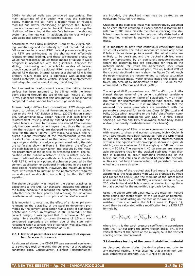
ΤΑ ΝΕΑ ΤΗΣ ΕΕΕΕΓΜ – Αρ. 74 – ΙΑΝΟΥΑΡΙΟΣ 2015 Σελίδα 17
2009) for shored walls was considered appropriate. The main advantage of this design was that the stabilised blocky material will still have a higher value of Young’s modulus and better interlocking of particles (i.e. blocks) than a conventional granular backfill, hence reducing the likelihood of trenching at the interface between the shoring system and the new wall. In addition, the tie rods will pro-vide additional safety against seismic loading.
According to the FWHA guidelines (Berg et al., 2009), slid-ing, overturning and eccentricity are not considered valid failure modes for shored RSW. Lateral pressures acting on the RSW are self-induced as the shoring wall effectively reduces external loading, and these self-induced pressures would not realistically induce these modes of failure in walls designed in accordance with the guidelines. Analyses for sliding, overturning and eccentricity modes of failure, though conducted for traditional RSW, are not required for shored RSW design. Internal failure of a shored RSW is the primary failure mode and is addressed with appropriate backfill materials, suitable vertical spacing of reinforcement and adequate reinforcement strength and lengths.
For inextensible reinforcement cases, the critical failure surface has been assumed to be bilinear with the lower point passing through the toe of the wall (Figure 1). The FHWA guidelines state that this assumption is conservative compared to observations from centrifuge modelling.
Internal design differs from conventional RSW design with regard to pullout of the reinforcement noted as an excep-tion to the RMS R57 Edition 2 Rev.1 (2007) design stand-ard. Conventional RSW design requires that each layer of reinforcement resist pullout by extending beyond the esti-mated failure surface. In the case of a shored RSW system, only the lower reinforcement layers (i.e., those that extend into the resistant zone) are designed to resist the pullout force for the entire “active” RSW mass. As a result, the re-quired pullout resistance of the reinforcement within the resistant zone is calculated as the pullout force derived us-ing a slope stability or wedge approach considering the fail-ure surface as shown in Figure 1. Therefore, the effect of the stabilisation is already taken into account by the mate-rial parameters of the backfill as presented below. The cal-culation of the pullout resistance in the resistant zone fol-lowed traditional design methods such as those outlined in RMS R57 ignoring any potential adhesion promoted by the cement stabilisation or additional interlocking in the case of steel ribbed reinforcement. However, the maximum tensile force with respect to rupture of the reinforcement requires an additional modification (exception) to the RMS R57 equation.
The above discussion was noted on the design drawings as exceptions to the RMS R57 standard, including the effect of the blocky behaviour in reducing the earth pressure applied onto the concrete face panels and reducing the maximum tensile force with respect to rupture of the reinforcement.
It is important to note that the effect of a higher pH envi-ronment on the durability of the steel reinforcement pro-moted by the cement stabilisation was a point of significant debate and further investigation is still required. For the current design, it was agreed that to achieve a 100 year design life a sacrificial corrosion thickness of 1.5 mm was considered appropriate on either side of the steel rein-forcement when a certain rate of corrosion was assumed, in addition to a galvanising protection of 85 m.
2.5.1 Material parameters and assessment of equiva-lent face earth pressure
As discussed above, the CS-SRSW was assumed equivalent to a synthetic rock simulating the behaviour of a weathered sandstone rock. Consequently, if cracks (discontinuities)
are included, the stabilised mass may be treated as an equivalent fractured rock mass.
Cracking of the stabilised mass was conservatively assumed to be very intense resulting in closely spaced discontinuities (60 mm to 200 mm). Despite the intense cracking, the sta-bilised mass is assumed to be only partially disturbed and the resulting medium is equivalent to a very blocky rock mass.
It is important to note that continuous cracks that could structurally control the failure mechanism would only occur if failure planes develop. As a result, the initial cracks are unlikely to be persistent and the cracked stabilised mass may be represented by an equivalent pseudo-continuum where the discontinuities are accounted for through the material model for which the Generalised Hoek-Brown (GHB) failure criterion was adopted. The equivalent GSI of the cracked stabilised mass is shown in Figure 7a. Although drainage measures are recommended to reduce saturation of the stabilised mass, water effects inside the cracks are taken into account by modification to the GSI value as rec-ommended by Marinos and Hoek (2000).
The adopted GHB parameters are: GSI = 45, σci = 1 MPa (target design value of the cement stabilised sandstone with a material reduction factor of 3 applied), mi = 17 (typ-ical value for sedimentary sandstone type rocks), and a disturbance factor D = 0. It is important to note that the assumed rock mass parameters are consistent with the parameters proposed for sandstone Class IV (Bertuzzi and Pells, 2002) which according to the Pells’ classification com-prises weathered sandstones with UCS > 2 MPa, defect spacing > 60 mm and 10% of allowable seams (clay seams and/or poor quality crushed/sheared rock bands).
Since the design of RSW is more conveniently carried out with respect to shear and normal stresses, Mohr- Coulomb (MC) parameters were back-calculated from the GHB model to suit the expected range of confining stresses/normal stresses. The equivalent MC envelope is shown in Figure 7b which gives an equivalent friction angle φ = 34º and cohe-sion c = 50 kPa. The equivalent MC parameters are reason-able considering that for the cracked stabilised mass dila-tion is expected to occur promoting interlocking of the blocks and that cohesion is obtained because the disconti-nuities are not fully interconnected, not persistent nor ori-ented in the same direction.
If the modulus of the cracked stabilised mass is calculated according to the relationship with GSI as proposed by Hoek and Diederichs (2006) and the modulus of the intact mass is assumed to be Ei = 1000 MPa, a cracked modulus Erm = 230 MPa is found which is somewhat similar in magnitude to that adopted for the monolithic approach low bound.
Using the above strength parameters, the maximum tensile force acting per metre width at the jth layer of reinforce-ment due to loads acting on the face of the wall in the non-resistant zone (i.e. inside the failure zone in Figure 1), could then be calculated with a modification to the RMS R57 formula by:
(3)
where K*1(Zj) is the earth pressure coefficient in accordance with RMS R57 but using the above friction angle, σ*vj is the vertical stress at the depth of the jth layer, Sv is the vertical spacing of the reinforcement.
3 Laboratory testing of the cement stabilised material
As discussed above, during the design phase and prior to any material testing, it was assumed that a minimum uni-axial compressive strength UCS = 3 MPa at 28 days
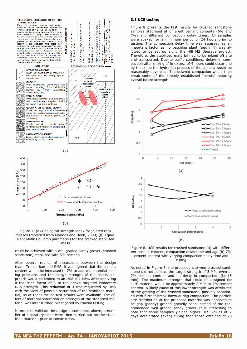
ΤΑ ΝΕΑ ΤΗΣ ΕΕΕΕΓΜ – Αρ. 74 – ΙΑΝΟΥΑΡΙΟΣ 2015 Σελίδα 18
(a)
(b)
Figure 7. (a) Geological strength index for jointed rock masses (modified from Marinos and Hoek, 2000) (b) Equiv-alent Mohr-Coulomb parameters for the cracked stabilised
mass
could be achieved with a well graded sandy gravel (crushed sandstone) stabilised with 5% cement.
After several rounds of discussions between the design team, Transurban and RMS, it was agreed that the cement content would be increased to 7% to address potential mix-ing problems and the design strength of the blocky ap-proach would be limited to an UCS = 1 MPa, after apply-ing a reduction factor of 3 to the above targeted laboratory UCS strength. This reduction of 3 was requested by RMS with the view of possible saturation of the stabilised mate-rial, as at that time no test results were available. The ef-fect of material saturation on strength of the stabilised ma-terial was later further investigated by triaxial testing.
In order to validate the design assumptions above, a num-ber of laboratory tests were then carried out on the stabi-lised material, prior to construction.
3.1 UCS testing
Figure 8 presents the test results for crushed sandstone samples stabilised at different cement contents (5% and 7%) and different compaction delay times. All samples were soaked for a minimum period of 24 hours prior to testing. The compaction delay time was assessed as an important factor as no batching plant (pug mill) was al-lowed to be set up along the Hill M2 Upgrade project. Therefore, the stabilised material had to be mixed off site and transported. Due to traffic conditions, delays in com-paction after mixing of in excess of 4 hours could occur and by that time the hydration process of the cement would be reasonably advanced. The delayed compaction would then break some of the already established “bonds” reducing overall future strength.
(a)
(b)
Figure 8. UCS results for crushed sandstone (a) with differ-ent cement content, compaction delay time and age (b) 7%
cement content with varying compaction delay time and curing
As noted in Figure 8, the proposed site-won crushed sand-stone did not achieve the target strength of 3 MPa even at 7% cement content and no delay in compaction (i.e.15 min). The maximum strength that could be assigned for such material would be approximately 2 MPa at 7% cement content. A likely cause of this lower strength was attributed to the grading of the crushed sandstone, possibly associat-ed with further break down during compaction. The particle size distribution of the proposed material was observed to be gap (poorly) graded gravelly sand instead of the rec-ommended well graded sandy gravel. It is interesting to note that some samples yielded higher UCS values at 7 days accelerated (oven) curing than those obtained at 28
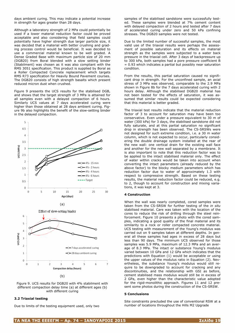
ΤΑ ΝΕΑ ΤΗΣ ΕΕΕΕΓΜ – Αρ. 74 – ΙΑΝΟΥΑΡΙΟΣ 2015 Σελίδα 19
days ambient curing. This may indicate a potential increase in strength for ages greater than 28 days.
Although a laboratory strength of 2 MPa could potentially be used if a lower material reduction factor could be proved acceptable and also considering that field samples could potentially have higher strength due larger particle size, it was decided that a material with better crushing and grad-ing process control would be beneficial. It was decided to use a commercial material known to be well graded. A Dense Graded Base with maximum particle size of 20 mm (DGB20) from Boral blended with a slow setting binder (Stabilment) was chosen as it was also compliant with the RMS 3051 specification. This product is supplied by Boral as a Roller Compacted Concrete replacement which targets RMS R73 specification for Heavily Bound Pavement courses. The DGB20 consists of high strength basalts which present reduced micron dust when crushed.
Figure 9 presents the UCS results for the stabilised DGB, and shows that the target strength of 3 MPa is attained for all samples even with a delayed compaction of 6 hours. Similarly UCS values at 7 days accelerated curing were higher than those obtained at 28 days ambient curing. Fig-ure 9b also highlights the benefit of the slow-setting binder in the delayed compaction.
(a)
(b)
Figure 9. UCS results for DGB20 with 4% stabilment with different compaction delay time (a) at different ages (b)
with different curing
3.2 Triaxial testing
Due to limits of the testing equipment used, only two
samples of the stabilised sandstone were successfully test-ed. These samples were blended at 7% cement content with delayed compaction of 2 hours and tested after 7 days of accelerated curing under zero and 50 kPa confining stresses. The DGB20 samples were not tested.
Due to the limited number of successful samples, the most valid use of the triaxial results were perhaps the assess-ment of possible saturation and its effects on material strength as the samples were subjected to a water back pressure in the triaxial cell. After 3 days of backpressure up to 300 kPa, both samples had a pore pressure coefficient B = 0.93 which indicates a partial but possibly near saturation condition.
From the results, this partial saturation caused no signifi-cant drop in strength. For the unconfined sample, an axial stress of 3 MPa was observed, comparable to the 2.9 MPa shown in Figure 8b for the 7 days accelerated curing with 2 hours delay. Although the stabilised DGB20 material has not been tested for the effects of saturation, it was as-sumed that similar results could be expected considering that this material is better graded.
The triaxial test results indicate that the material reduction factor of 3 to account for saturation may have been too conservative. Even under a pressure equivalent to 30 m of water (300 kPa) for 3 days, the stabilised sandstone did not fully saturate, and at this partial saturation no significant drop in strength has been observed. The CS-SRSWs were not designed for such extreme condition, i.e. a 30 m water column, which is not expected to occur, particularly consid-ering the double drainage system installed at the rear of the new wall: one vertical drain for the existing wall face and another for the new wall separated by a membrane. It is also important to note that this reduction factor was to be applied to the intact stabilised material only. The effect of water within cracks would be taken into account when converting the intact parameters (already reduced by the above factor) to the blocky medium parameters which has reduction factor due to water of approximately 1.3 with respect to compressive strength. Based on these testing results, the material reduction factor could be reduced, e.g. to 2, though to account for construction and mixing varia-tions, it was kept at 3.
4 Construction
When the wall was nearly completed, cored samples were taken from the CS-SRSW for further testing of the in situ stabilised material. Care was taken with the location of the cores to reduce the risk of drilling through the steel rein-forcement. Figure 10 presents a photo with the cored sam-ples, indicating a good quality of the final material and its similarity to a rock or roller compacted concrete material. UCS testing with measurement of the Young’s modulus was carried out on 9 samples taken at different depths. In gen-eral all these samples had ages in excess of 28 days but less than 90 days. The minimum UCS observed for those samples was 5.9 MPa, maximum of 12.3 MPa and an aver-age of 8.3 MPa. The intact or substance Young’s modulus varied between 10 GPa and 12 GPa which indicates that the predictions with Equation (1) would be acceptable or using the upper values of the modulus ratio in Equation (2). Nev-ertheless, the substance Young’s modulus would still re-quire to be downgraded to account for cracking and any discontinuities, and the relationship with GSI as before, cement stabilised mass modulus would still be in excess of 2 GPa, even higher than the characteristic value adopted for the rigid-monolithic approach. Figures 11 and 12 pre-sent some photos during the construction of the CS-SRSW.
5 Conclusions
Site constraints precluded the use of conventional RSW at a number of locations throughout the Hills M2 Upgrade
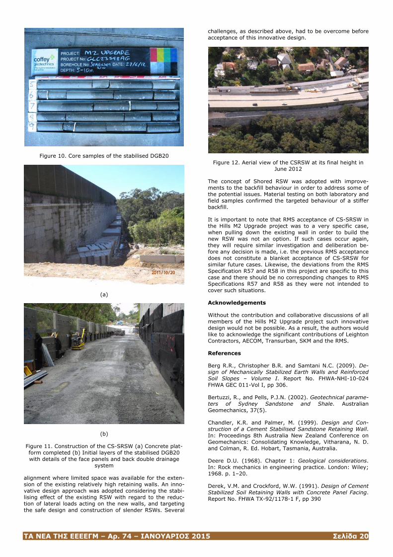
ΤΑ ΝΕΑ ΤΗΣ ΕΕΕΕΓΜ – Αρ. 74 – ΙΑΝΟΥΑΡΙΟΣ 2015 Σελίδα 20
Figure 10. Core samples of the stabilised DGB20
(a)
(b)
Figure 11. Construction of the CS-SRSW (a) Concrete plat-form completed (b) Initial layers of the stabilised DGB20 with details of the face panels and back double drainage
system
alignment where limited space was available for the exten-sion of the existing relatively high retaining walls. An inno-vative design approach was adopted considering the stabi-lising effect of the existing RSW with regard to the reduc-tion of lateral loads acting on the new walls, and targeting the safe design and construction of slender RSWs. Several
challenges, as described above, had to be overcome before acceptance of this innovative design.
Figure 12. Aerial view of the CSRSW at its final height in June 2012
The concept of Shored RSW was adopted with improve-ments to the backfill behaviour in order to address some of the potential issues. Material testing on both laboratory and field samples confirmed the targeted behaviour of a stiffer backfill.
It is important to note that RMS acceptance of CS-SRSW in the Hills M2 Upgrade project was to a very specific case, when pulling down the existing wall in order to build the new RSW was not an option. If such cases occur again, they will require similar investigation and deliberation be-fore any decision is made, i.e. the previous RMS acceptance does not constitute a blanket acceptance of CS-SRSW for similar future cases. Likewise, the deviations from the RMS Specification R57 and R58 in this project are specific to this case and there should be no corresponding changes to RMS Specifications R57 and R58 as they were not intended to cover such situations.
Acknowledgements
Without the contribution and collaborative discussions of all members of the Hills M2 Upgrade project such innovative design would not be possible. As a result, the authors would like to acknowledge the significant contributions of Leighton Contractors, AECOM, Transurban, SKM and the RMS.
References
Berg R.R., Christopher B.R. and Samtani N.C. (2009). De-sign of Mechanically Stabilized Earth Walls and Reinforced Soil Slopes – Volume I. Report No. FHWA-NHI-10-024 FHWA GEC 011-Vol I, pp 306.
Bertuzzi, R., and Pells, P.J.N. (2002). Geotechnical parame-ters of Sydney Sandstone and Shale. Australian Geomechanics, 37(5).
Chandler, K.R. and Palmer, M. (1999). Design and Con-struction of a Cement Stabilised Sandstone Retaining Wall. In: Proceedings 8th Australia New Zealand Conference on Geomechanics: Consolidating Knowledge, Vitharana, N. D. and Colman, R. Ed. Hobart, Tasmania, Australia.
Deere D.U. (1968). Chapter 1: Geological considerations. In: Rock mechanics in engineering practice. London: Wiley; 1968. p. 1–20.
Derek, V.M. and Crockford, W.W. (1991). Design of Cement Stabilized Soil Retaining Walls with Concrete Panel Facing. Report No. FHWA TX-92/1178-1 F, pp 390

ΤΑ ΝΕΑ ΤΗΣ ΕΕΕΕΓΜ – Αρ. 74 – ΙΑΝΟΥΑΡΙΟΣ 2015 Σελίδα 21
DoT- Department of Transport. (1986). Cementitious stabi-lizers in road construction. Technical Recommendations for Highways, TRH 13, Department of Transport, Pretoria.
Hoek, E. and Diederichs, M.S. (2006). Empirical estimation of rock mass modulus. Int J Rock Mech Min Sci, 43:203–2015.
Indraratna, B. (1990). Development and applications of a synthetic material to simulate soft sedimentary rocks. Geotechnique 40, No. 2, 189–200.
Ismail, M.A. (2005). Performance of cement-stabilised re-taining walls. Canadian Geotechnical Journal, 42:876-891.
Karimpour, H. and Lade, P. (2010). Time Effects Relate to Crushing in Sand. J. Geotech. Geoenviron. Eng., 136(9), 1209–1219
Marinos, P and Hoek, E. (2000). GSI – A geologically friend-ly tool for rock mass strength estimation. Proc. GeoEng2000 Conference, Melbourne, pp. 1422-1442.
(ISSMGE Bulletin: Volume 8, Issue 5, pp. 23-37)
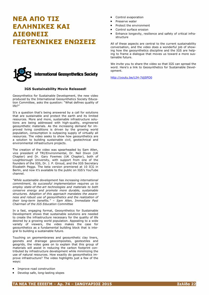
ΤΑ ΝΕΑ ΤΗΣ ΕΕΕΕΓΜ – Αρ. 74 – ΙΑΝΟΥΑΡΙΟΣ 2015 Σελίδα 22
ΝΕΑ ΑΠΟ ΤΙΣ ΕΛΛΗΝΙΚΕΣ ΚΑΙ ΔΙΕΘΝΕΙΣ ΓΕΩΤΕΧΝΙΚΕΣ ΕΝΩΣΕΙΣ
IGS Sustainability Movie Released!
Geosynthetics for Sustainable Development, the new video produced by the International Geosynthetics Society Educa-tion Committee, asks the question: “What defines quality of life?”
It’s a question that’s being answered by a call for solutions that are sustainable and protect the earth and its limited resources. More and more, sustainable infrastructure solu-tions are being addressed with high-quality, engineered geosynthetic materials. As the increasing demand for im-proved living conditions is driven by the growing world population, consumption is outpacing supply of virtually all resources. The video seeks to show how geosynthetics are a solution to building sustainable civil, geotechnical and environmental infrastructure projects.
The creation of the video was spearheaded by Sam Allen, vice president of TRI/Environmental, Dr. Neil Dixon (UK Chapter) and Dr. Gary Fowmes (UK Chapter), both of Loughborough University, with support from one of the founders of the IGS, Dr. J. P. Giroud, and the IGS Secretary Elizabeth Peggs. The beta version premiered at 10 ICG in Berlin, and now it’s available to the public on IGS’s YouTube channel.
“While sustainable development has increasing international commitment, its successful implementation requires us to employ state-of-the-art technologies and materials to both conserve energy and promote more durable, sustainable structures. Adoption of this approach mandates the aware-ness and robust use of geosynthetics and the realization of their long-term benefits.” – Sam Allen, Immediate Past Chairman of the IGS Education Committee
In a fast, engaging format, Geosynthetics for Sustainable Development shows that sustainable solutions are needed to create the infrastructure necessary for the quality of life desired by a growing world population. Appealing to a wide variety of viewers, the video makes the case for geosynthetics as a fundamental building block that is inte-gral to building a sustainable future.
Touching on geomembranes and geosynthetic clay liners, geonets and drainage geocomposites, geotextiles and geogrids, the video goes on to explain that this group of materials will assist in reducing the carbon footprint con-tributed by infrastructure development while minimizing the use of natural resources. How exactly do geosynthetics im-prove infrastructure? The video highlights just a few of the ways:
• Improve road construction • Develop safe, long-lasting slopes
• Control evaporation • Preserve water • Protect the environment • Control surface erosion • Enhance longevity, resilience and safety of critical infra-
structure
All of these aspects are central to the current sustainability conversation, and the video does a wonderful job of show-ing how the geosynthetics discipline and the IGS are help-ing to frame a dialogue that moves us toward a more sus-tainable future.
We invite you to share the video so that IGS can spread the word. Here's a link to Geosynthetics for Sustainable Devel-opment. http://youtu.be/LIH-7djSPO0
ΤΑ ΝΕΑ ΤΗΣ ΕΕΕΕΓΜ – Αρ. 74 – ΙΑΝΟΥΑΡΙΟΣ 2015 Σελίδα 23
ΠΡΟΣΕΧΕΙΣ ΓΕΩΤΕΧΝΙΚΕΣ ΕΚΔΗΛΩΣΕΙΣ
Για τις παλαιότερες καταχωρήσεις περισσότερες πληροφορί-ες μπορούν να αναζητηθούν στα προηγούμενα τεύχη του «περιοδικού» και στις παρατιθέμενες ιστοσελίδες.
1st IAGEM International Conference 2015 Geotechnical, Structural and Environmental
Monitoring of Civil Works 2nd Quarter 2015 - L'Aquila, Italy
www.iagem.org/#!e1-conference-home/c10xu
The 1st IAGEM International Conference will showcase the significant impact that Geotechnical, Structural and Environmental Monitoring has on our society today.
The one day event will offer case studies and strategies that demonstrate innovation, skills and best practice, and help delegates understand the emerging technolo-gies and techniques guiding industry.
Enormous benefits can be realized through emerging technologies, with considerably enhanced efficiencies, economics, resilience and adaptability.
Building upon the technical expertise and authority of IAGEM as the prime international organization of Geotech-nical, Structural and Environmental Monitoring Profession-als, the conference will explore the contributions that Moni-toring can make to solving major problems of today and the future.
Four Global Themes are being proposed to form central pillars of the technical programme. These themes will be introduced by high-level visionary keynote speak-ers and then be explored by different style sessions.
The event will provide a platform for engineers and plan-ners to meet and share experiences from these large inter-national projects and overseas counterparts. Delegates will discuss and learn about the planning and development of Geotechnical, Structural and Environmental Monitoring spe-cialist sector.
The Conference will focus on:
• Learn about progression and the modernisation of engi-neering underground space
• Witness innovative programmes and examples of intelli-gent solutions
• Gain understanding of new practices shaping our under-ground infrastructure
• Support and develop ability to respond to industry needs
• Experience a diverse networking opportunity
IAGEM Gaetano Poli Street, 43 80055 Portici Naples – Italy
5th Annual Underground Infrastructure & Deep Foundations Qatar, 31 May - 03 June, 2015, Doha, Doha, Qatar, www.undergroundfoundations.com
5th International Congress on Construction History, June 3rd-7th, 2015, Chicago, USA, www.5icch.org
2nd International Geo-Cultural Symposium "Sigri 2015"
4-6 June 2015, Mytilene, Greece www.sigri.gr/index.php/en
Lesvos Island is located in the northeastern Aegean Sea and it is the third biggest in size and population island of Greece. Its natural beauty as well as its cultural heritage makes Lesvos a center of attraction for international tour-ism. Due to its history, geological uniqueness and economic growth scientists of several fields (geology, archaeology, history, religious history, folklore, literature, architecture, painting, and environment) are attracted.
Legend has it that Μuses favored the island, because the inhabitants buried Orpheu’s head, son of Musa Kalliope, when it drifted ashore. For that reason, it is said, that arts and science flourished in the island. Lesvos Island is the birthplace of famous poets, painters, musicians and philos-ophers from the ancient times (Arion, Sappho, Alcaeus, Theophrastus) till modern times (Stratis Mirivilis, Ilias Venezis, Odysseus Elytis, Theophilos Hatzimichail).
Million years ago, the eruption of a volcano created the petrified forest of Lesvos, one of the most spectacular natu-ral monuments of geological heritage that is worth visiting. The intensive volcanic activity of the area shaped the geo-logical structure of the island. The eastern side is rich in salt lakes, rivers, fields of reeds, vast olive groves and pine forests while the western side resembles a barren island.
The Gulfs of Gera and Kalloni are important habitat of rare species that contribute to the biodiversity of the island.
Several rare species of birds gather in these areas and are the object of observation for the visitors especially in Spring and Autumn. Among the most interesting “visitors” of the island are pink flamingos.
Lesvo’s with its abundant natural resources, archaeological sites and monuments and its unique view of the Aegean Sea and of the cost of Minor Asia is a place of high im-portance and rare beauty.
The purpose of the symposium is to highlight and interpret the geological phenomena of the island, while also explain-ing their influence in its cultural evolution.
Symposium Topics
1. Applied Geography 2. Aquaculture 3. Cartography 4. Climatology & Meteorology 5. Cultural Geography 6. Environment: 7. Environmental Education & Awareness 8. Field Methods
ΤΑ ΝΕΑ ΤΗΣ ΕΕΕΕΓΜ – Αρ. 74 – ΙΑΝΟΥΑΡΙΟΣ 2015 Σελίδα 24
9. Fisheries, Environmental Impacts, Monitoring & Man-agement
10. G.I.S 11. Geomorphology 12. Hazards, Risks & Disasters 13. Land Use 14. Marine Biology& Ecology 15. Marine & CoastalResources 16. Marine Geology& Geophysics/ Seismology/ Sediment
logy/ MarineMinerals 17. Maritime Technology & Applications 18. Natural Resources 19. Oceanography (Physical, Chemical) 20. Physical Geography 21. Remote Sensing 22. Social Geography 23. Spatial Analysis& Modeling 24. Water Resources& Hydrology 25. History 26. Archeology 27. Literature 28. Natural Hazards 29.Folklore
Secretary Moel Conferences Ms Maria Kavvadia Tel.: (+30) 2106203614 Fax: (+30) 2108078342 Email: [email protected]
2nd International Course on Geotechnical and Structural Monitoring, 4-5-6 June 2015, Poppi, Tuscany, Italy, www.geotechnicalmonitoring.com/en/home-2
ISFOG 2015 3rd International Symposium on Frontiers in Offshore Geotechnics, Oslo, Norway, 10-12 June 2015, www.isfog2015.no
6o ΔΙΕΘΝΕΣ ΣΥΝΕΔΡΙΟ ΑΣΦΑΛΤΙΚΑ ΜΙΓΜΑΤΑ ΚΑΙ ΟΔΟ-ΣΤΡΩΜΑΤΑ, Θεσσαλονίκη, 10-12 Ιουνίου 2015, http://iconfbmp.civil.auth.gr
83rd ICOLD Annual Meeting & Congress Hydropower’ 15, 13-20 June 2015, Stavanger, Norway, www.icoldnorway2015.org
Géotechnique Symposium in Print 2015 Geotechnical Earth-quake Engineering, London, 15 June, 2015, www.ice.org.uk/events/geotechnique-symposium-in-print-2015
DMT 15 The 3rd International Conference on the Flat Dila-tometer, Rome 15-17 June 2015, www.dmt15.com
Summer School Series in Greece "SOUTH AEGEAN CRUST PROCESS" - "SANTORINI VOLCANOTECTONIC LAB", 15-20 of June 2015, Santorini, Greece, [email protected]; [email protected]
The First Kazakhstan – USA Geotechnical Engineering Workshop, Astana and Almaty, Kazakhstan, 13-16 July 2015, [email protected]
ICGE 2015 International Conference in Geotechnical Engi-neering – Colombo-2015, 10 - 11 August 2015, Colombo, Colombo, Sri Lanka, http://www.slgs.lk/?p=564
20 August 2015, Hanoi, Vietnam
The Vietnamese Society for Soil Mechanisc and Geotech-nical Engineering (VSSMGE) and the Thuyloi University will organize the one-day seminar on Numerical Analysis in Geotechnics (NAG2015), on 20th August 2015, in Hanoi. This seminar is planned to be held every year in Vietnam. NAG2015 create a forum, where the users of different nu-merical methods/computer codes can exchange their expe-rience and knowledge relating to the use of numerical methods in geotechnical engineering, including engineering applications and scientific achievements.
The seminar covers applications of numerical methods in geotechnical engineering. Topics include: constitutive mod-eling, computer codes and algorithms, parameter determi-nation in field and laboratory tests, ground improvement and reinforcement, embankments and slopes, shallow and deep foundations, deep excavations and retaining walls, tunnels, infrastructure, groundwater flow and coupled anal-ysis, dynamic applications, offshore applications, etc.
So far we already got the following early registered presen-tations:
• "Effect of the raft-pile foundation of transmission tower on the design of adjacent shoring structure" by Prof. John Curran, Dr. Kien Dang, and Dr. Thamer Yacoub, (Rocscience, Canada)
• "Modelling of Embankments, Reclamation and Improved Ground by Vacuum Consolidation" by Dr. William Cheang (Plaxis AsiaPac, Singapore)
• "Numerical modelling of cyclic behavior of a dyke pro-ject under seismic and waves actions", by Prof. Alain Guilloux, and Dr. Khoa Van Nguyen (Terrasol, France)
• "Development of a FEM code for groundwater modeling and land subsidence analysis of a multiaquifer system in an expanding city", by Dr. Pham Huy Giao (AIT, Thai-land)
• "Deep excavations and tunneling works of MRT in Tai-wan and Indonesia" by Prof. Benson Hsiung (CECI, Tai-wan), and
• "3D modelling of piled raft and piled foundations" by Dr. Phung Duc Long (VSSMGE, Vietnam)
CONTACT VSSMGE Office, Building CIC-CDC, 37 Le Dai Hanh Street, Hai Ba Trung District, Hanoi. The Seminar Secretariat Email: [email protected]
China Shale Gas 2015 - an ISRM Specialized Conference, 6-8 September 2015, Wuhan, China, http://english.whrsm.cas.cn/ic/ic/201405/t20140509_120692.html
ΤΑ ΝΕΑ ΤΗΣ ΕΕΕΕΓΜ – Αρ. 74 – ΙΑΝΟΥΑΡΙΟΣ 2015 Σελίδα 25
"Underground Construction" Conference, 8-9 September 2015, Krakow, Poland, www.inzynieria.com
International Benchmark 2015 13th International Benchmark on the
Numerical Analysis of Dams 9 - 11 September 2015, Lausanne | Switzerland
http://icold2015bmw.epfl.ch
On behalf of the Swiss Committee on Dams it is our pleas-ure to invite you to participate in the 13th International Benchmark Workshop on Numerical Analysis of Dams - at EPFL, Lausanne, in Switzerland, from 9th to the 11th Sep-tember 2015. The Benchmark is jointly organized with the ICOLD - Committee on Computational Aspects of Analysis and Design of Dams. With over 150 large dams (of which 25 over 100 m high), Switzerland is a hub for Dam Engi-neering. The Swiss Federal Office of Energy (SFOE) requires that Owners verify their schemes including “dams” for seismic loading. By 2015, a vast majority of seismic verifi-cations shall have been performed in accordance with the most recent Guidelines published by the SFOE thus repre-senting a milestone in Swiss Dam Engineering. It would be a pleasure to meet you at EPFL in September 2015!
The Benchmark concept
The Benchmark sets a framework for Engineers, Owners and Researchers to perform and share their experiences for predefined themes, as follows:
Before the workshop
a. The organizers formulate “problems” for comparative analysis by participants and hand over basic data;
b. Participants submit their reply to the problem;
c. The organizers prepare a reference reply and a summary report of all contributions.
During the workshop
d. Participants present their replies
e. Organizers present reference reply & summary
After the workshop, a compilation of the contributions and the wrap-up report is published online.
Host and Contact
Laboratory of Hydraulic Constructions (LCH) Ecole Polytechnique Fédérale de Lausanne (EPFL) Station18, CH-1015 Lausanne, Switzerland Conference email address: [email protected]
International Symposium on Geohazards and Geomechanics
10-11 September, 2015, Coventry, U.K. www.warwick.ac.uk/isgg2015
This symposium aims to bring together the complementary expertise of world leading groups carrying out research on the engineering assessment, prevention and mitiga-tion of geohazards.
To mitigate against these disasters we need for instance to achieve better models for a more rational risk assess-ment of areas prone to landslides, investigate the geomechanical conditions leading to the onset of landslides (e.g. earthquakes), model debris flows and mudflows to estimate run-out distances and destructive power of the landslide materials, improve our modeling capabilities of fluid – ground interaction.
Prevention, preparedness and mitigation of geohazards rely on sound geo-engineering which requires competences in geomechanics, numerical modelling, constitutive models for soils, hazard zonation and risk assessment.
Main Topics
- Landslides
Debris flows Rock falls Rain-induced landslides Earthquake-induced landslides Physical modeling and material testing Monitoring, prediction and warning Remedial measures & prevention works Liquefaction Case studies and field survey reports Ground improvement techniques Slope stability
- Numerical modelling techniques
Discrete/particle methods Continuum methods
- Hazard Zonation
Landslide & geohazard susceptibility Hazard/risk mapping
- Other geohazards
Gas and leachates Floods
Coordinator: Dr. Stefano Utili School of Engineering, University of Warwick, UK
Symposium website: http://www.warwick.ac.uk/isgg2015
For any information, secretariat email: [email protected]
24th European Young Geotechnical Engineers Conference in Durham, UK, 11-12 September, 2015, https://www.dur.ac.uk/conference.booking/details/?id=419

ΤΑ ΝΕΑ ΤΗΣ ΕΕΕΕΓΜ – Αρ. 74 – ΙΑΝΟΥΑΡΙΟΣ 2015 Σελίδα 26
16th European Conference on Soil Mechanics and Geotechni-cal Engineering “Geotechnical Engineering for Infrastructure and Development”, 13 - 17 September 2015, Edinburgh, UK, www.xvi-ecsmge-2015.org.uk
Workshop on Volcanic Rocks & Soils, 24 - 25 September 2015, Isle of Ischia, Italy, www.associazionegeotecnica.it
The 7th International Symposium on Roller Compacted Con-crete (RCC) Dams, Chengdu, China, Sept. 24th -25th, 2015, www.chincold.org.cn
Athens 2015 International Landfill Mining Conference, Sep-tember 24-25, 2015, Athens, http://www.erasmus.gr/microsites/1050/welcome-address
TranSoilCold 2015 - The 2nd International Symposium on Transportation Soil Engineering in Cold Regions, September 24-26, 2015, Novosibirsk, Russia, http://transoilcold2015.stu.ru/index.htm
GE Basements and Underground Structures Conference 2015, 6 - 7 October 2015, London, UK, http://basements.geplus.co.uk
EUROCK 15 ISRM European Regional Symposium & 64th Geomechanics Colloquy, 7 – 9 October 2015, Salzburg, Austria, www.eurock2015.com
Shotcrete for Underground Support XII New Developments in Rock Engineering, TBM tunnelling, Deep Excavation and Underground Space Technology, October 11-13, 2015, Sin-gapore, www.engconf.org/conferences/civil-and-environmental-engineering/shot-crete-for-underground-support-xii
5th International Symposium on Geotechnical Safety and Risk (ISGSR 2015), 13-16 October 2015, Rotterdam, The Netherlands www.isgsr2015.org
HYDRO 2015, 26-28 October 2015, Bordeaux, France, www.hydropower-dams.com/pdfs/hydro2015.pdf
International Conference on Engineering Geology in New Millennium, 26-31 October 2015, New Delhi, India, http://isegindia.org/pdfs/1st%20circular-international-IAEG.pdf
6th International Conference on Earthquake Geotechnical Engineering, 2-4 November 2015, Christchurch, New Zea-land, www.6icege.com
SEOUL 2015 - 25th World Road Congress Roads and Mobil-ity – Creating New Value from Transport, 2–6 November, 2015, Seoul, Republic of Korea, http://www.aipcrseoul2015.org
4ο Πανελλήνιο Συνέδριο Ααναστηλώσεων, Νοέμβριος 2015, Θεσσαλονίκη, www.etepam.gr.
The 15th Asian Regional Conference on Soil Mechanics and Geotechnical Engineering, 9-13 November 2015, Fukuoka, Japan, http://www.15arc.org
15th Pan-American Conference on Soil Mechanics and Geo-technical Engineering, 15 - 18 November 2015, Buenos Aires, Argentina, http://conferencesba2015.com.ar
16 -18 November 2015, Osaka, Japan
www.geomate.org
The Fifth International Conference on Geotechnique, Con-struction Materials and Environment, GEOMATE 2015, will be held in Osaka from 16 to 18 November 2015, in con-junction with the Kansai University, Japan Geotechnical Society, GEOMATE International Society, AOI-Engineering, Useful Plant Spread Society, HOJUN and Glorious Interna-tional.
It aims to provide a great opportunity to share common interests in geo-engineering, construction materials, envi-ronmental issues, water resources, and earthquake and tsunami disasters.
The conference will be dedicated to those affected by the tragic Tohoku-Kanto earthquake which occurred on Friday 11 March 2011, at 14:46 Japan Standard Time, in which the north east of Japan was severely damaged.
The four previous events were held in Tsu City, Mie, Japan; Kuala Lumpur, Malaysia; Nagoya, Japan and Brisbane, Aus-tralia.
The organizers encourage and welcome your enthusiastic participation and look forward to receiving contributions demonstrating in-depth multidisciplinary technology to-wards new research and development.
Conference themes will consider papers in the following topics:
• Advances in Composite Materials • Computational Mechanics • Foundation and Retaining Walls • Slope Stability • Soil Dynamics • Soil-Structure Interaction • Pavement Technology • Tunnels and Anchors • Site Investigation and Rehabilitation • Ecology and Land Development • Water Resources Planning • Environmental Management • Earthquake and Tsunami Issues • Safety and Reliability • Geo-Hazard Mitigation • Case History and Practical Experience • Others
Conference Correspondence Prof. Dr. Zakaria Hossain, General Secretary, Dept. of Env. Sci. & Tech., Mie University, Japan, Prof. Dr. Akira Kobayashi (Chairman) Dept. of Civil and Environmental Engineering, Kansai Uni-versity, Osaka, Japan, A/Prof. Dr. Sinya Inazumi (Vice-Chairman), National Ins. of Tech., Akashi, Japan, E-mail: [email protected] Tel & Fax: +81-59-231-9578
VIII South American Congress on Rocks Mechanics, 15 - 18 November 2015, Buenos Aires, Argentina,
ΤΑ ΝΕΑ ΤΗΣ ΕΕΕΕΓΜ – Αρ. 74 – ΙΑΝΟΥΑΡΙΟΣ 2015 Σελίδα 27
http://conferencesba2015.com.ar
Sixth International Conference on Deformation Characteris-tics of Geomaterials IS Buenos Aires 2015, November 15th to 18th 2015, www.saig.org.ar/ISDCG2015
Geo-Environment and Construction, 26-28 November 2015, Tirana, Albania, Prof. Dr. Luljeta Bozo, [email protected]; [email protected]
The 1st International Conference on Geo-Energy and Geo-Environment (GeGe2015) 4th and 5th December 2015, Hong Kong, http://gege2015.ust.hk
2015 6th International Conference Recent Advances in Ge-otechnical Engineering and Soil Dynamics, December 7-11, 2015, New Delhi (NCR), India, [email protected]; [email protected], [email protected]; [email protected], [email protected], [email protected]
Southern African Rock Engineering Symposium an ISRM Regional Symposium, 5 January 2016, Cape Town, South Africa, http://10times.com/southern-african-rock
GeoAmericas 2016 3rd Panamerican Conference on Geosynthetics, 11 – 14 April 2016, Miami Beach, USA, www.geoamericas2016.org
World Tunnel Congress 2016 “Uniting the Industry”, April 22-28, 2016, San Francisco, USA, http://www.wtc2016.us
7th In-Situ Rock Stress Symposium 2016 - An ISRM Spe-cialised Conference, 10-12 May 2016, Tampere, Finland, www.rs2016.org
84th ICOLD Annual Meeting, 16-20 May 2016, Johannes-burg, South Africa, www.sancold.org.za/index.php/activities/icold-annual-meeting-2016
13th International Conference Underground Construction Prague 2016 and 3rd Eastern European Tunnelling Confer-ence (EETC 2016), 23 to 25 May 2016, Prague, Czech Re-public, www.ucprague.com
GEOSAFE: 1st International Symposium on Reducing Risks in Site Investigation, Modelling and Construction for Rock Engineering - an ISRM Specialized Conference, 25 – 27 May 2016, Xi’an, China, www.geosafe2016.org/dct/page/1
NGM 2016 - The Nordic Geotechnical Meeting, 25 - 28 May 2016, Reykjavik, Iceland, www.ngm2016.com
19th Southeast Asian Geotechnical Conference & 2nd AGSSEA Conference Deep Excavation and Ground Im-provement, 31 May – 3 June 2016, Subang Jaya, Malaysia, [email protected]
ISSMGE TC211 Conference Session within the framework of the 19th Southeast Asian Geotechnical Conference “GROUND IMPROVEMENT works: Recent advances in R&D, design and QC/QA”
ISL 2016 12th International Symposium on Landslides Expe-rience, Theory, Practice, Napoli, June 12th-19th, 2016, www.isl2016.it
6th International Conference on Recent Advances in Ge-otechnical Earthquake Engineering and Soil Dynamics August 1-6, 2016, Greater Noida (NCR), India, www.6icragee.com
4th GeoChina International Conference Sustainable Civil Infrastructures: Innovative Technologies for Severe Weath-ers and Climate Changes, July 25-27, 2016, Shandong, China, http://geochina2016.geoconf.org
EUROC 2016 - ISRM European Regional Symposium Rock Mechanics & Rock Engineering: From Past to the Future, 29-31 August 2016, Ürgüp-Nevşehir, Cappadocia, Turkey http://eurock2016.org
3rd ICTG – 3rd International Conference on Transportation Geotechnics 4 - 7 September 2016, Guimaraes, Portugal, www.civil.uminho.pt/3rd-ICTG2016
SAHC 2016 10th international Conference on
Structural Analysis of Historical Constructions 13-15 September 2016, Leuven, Belgium
www.sahc2016.be
The Raymond Lemaire Centre for Conservation and the Civil Engineering Department of the Catholic University Leuven, with the support of the UNESCO chair on preventive con-servation, maintenance and monitoring of the monuments and sites, will organize the 10th anniversary edition of the International Conference on Structural Analysis of Historical Constructions (SAHC2016).
The theme of the conference is “Anamnesis, Diagnosis, Therapy, Controls”, which emphasizes the importance of all steps of a restoration process in order to obtain a thorough understanding of the structural behavior of built cultural heritage. Papers are invited for presentation and poster sessions on general topics and specific themes.
Conference topics
1. Preventive conservation, maintenance and monitoring
2. Historical and innovative mortars and binders
3. Non-destructive testing, inspection and structural moni-toring techniques
4. Adobe and vernacular constructions
5. Conservation of the 20th century architectural heritage
6. Foundation and geotechnical problems
7. Structural assessment and intervention of archaeologi-cal sites
8. Theory and practice of conservation
9. Repair and strengthening techniques
10. Analytical and numerical approaches
11. In-situ and laboratory experimental results
12. Interaction between innovative and traditional materi-als
13. Seismic behavior and retrofitting
14. Rehabilitation, re-use and valorization of cultural herit-age buildings
15. Case studies
ΤΑ ΝΕΑ ΤΗΣ ΕΕΕΕΓΜ – Αρ. 74 – ΙΑΝΟΥΑΡΙΟΣ 2015 Σελίδα 28
13 Baltic States Geotechnical Conference Historical Experi-ences and Challenges of Geotechnical Problems in Baltic Sea Region, 15 - 17 September 2016, Vilnius, Lithuania, http://www.13bsgc.lt
EuroGeo 6 – European Regional Conference on Geo-synthetics, 25 – 29 Sep 2016, Istanbul, Turkey, www.eurogeo6.org
ARMS 9 9th Asian Rock Mechanics Symposium
ISRM Regional Symposium October 2016, Bali, Indonesia
Contact Person: Dr Ridho Wattimena
Indonesian Rock Mechanics Society (IRMS)
Telephone: +22 250 2239
GeoAsia 6 - 6th Asian Regional Conference on Geosynthetics 8-11 November 2016, New Delhi, India, http://seags.ait.asia/news-announcements/11704
Recent Advances in Rock Engineering - RARE 2016 - an ISRM Specialised Conference
16-18 November 2016, Bangalore, India
Contact Person: Dr V. Venkntesvarlu Address PO: Champions Reefs 563 117 ( Kolar Gold Fields, Kamataka) India Telephone: +91 8153 275000 Fax: +91 8153 275002 E-mail: [email protected]
AfriRock 2017 1st African Regional Rock Mechanics Symposium
12 – 17 February 2017, Cape Tpwn, South Africa
The first African Regional Rock Mechanics Symposium is to be held in Cape Town 2017. Mining has traditionally been a mainstay of African economies, while Oil and Gas industries are rapidly growing throughout Africa. Infrastructure is be-ing developed to support these industries. Rock engineering
design is and therefore will continue to be essential for the growth of the continent.
Africa is richly endowed with mineral reserves and ranks first or second in quantity of world reserves of bauxite, co-balt, industrial diamonds, phosphate and platinum group metals (PGM). The map shows minerals produced in African countries.
The mining and quarrying of mineral products represents 20% of Africa’s economic activity. Africa produced 75% of the global PGM in 2014, with 68% coming from the Bushveld Complex in South Africa and 7% from the Great Dyke in Zimbabwe. Africa produced 54% of the global dia-monds by market value in 2013, with Botswana, second only to Russia, producing 22%, Angola producing 10%, South Africa 8.7%, Namibia 8% and the remainder from Zimbabwe and the DRC. Gold is a major export product for many African countries.
South Africa and Ghana are ranked 6th (5%) and 10th (3%) in world gold production. Rock mechanics challenges range from large open pit slopes to extremely deep under-ground mines
The map shows oil and gas producing African countries and African countries with potential shale oil & gas resources. Africa accounts for 7.8% of global oil reserves, with 84.5% of the African oil reserves concentrated in the four OPEC countries; Libya, Nigeria, Angola and Algeria.
Other countries with notable proven oil resources are Egypt, South Sudan and Gabon. Fifteen countries exported oil totalling 6.55 million bpd in 2012, with Nigeria producing the most (2.5 million bpd), followed by Nigeria, Angola, Algeria, Libya and Egypt. Africa’s share of global natural gas reserves is 7.7%, with Nigeria and Algeria being the top producers.
Five other African countries have proven natural gas reserves in excess of 100 billion m3 and are producing gas; Egypt, Libya, Angola, Cameroon and Mozambique. There are large deposits of shale oil and gas in South Africa and across North Africa, which provide some exciting pro-spects for Africa. Algeria's shale gas potential is 20 trillion m3, which would rank it third in the world after China and Argentina and slightly ahead of the USA.
Other significant potential shale gas resources include; South Africa (10.9 trillion m3, ranked eighth), Libya (3.5 trillion m3) and Egypt (2.8 trillion m3). Both Algeria and Egypt have notable shale oil resources.
There are many African civil infrastructure projects that are in progress or planned. A few of the major projects with rock mechanics interest in the Southern African Develop-ment Community (SADC) are listed here.
The Ingula Pumped Storage scheme is under construction and located in KwaZulu Natal, South Africa. Phase II of the Lesotho Highlands Water project (LHWP) has commenced and includes the construction of the Polihali dam and trans-fer tunnel and a hydroelectric generation plant.
The Kariba Dam, on the Zambezi river, which forms the boundary between Zambia and Zimbabwe is the largest man made reservoir in the world and was constructed in 1960. After providing power to the Southern Africa for more than 50 years (1.8 GW currently), it requires major rehabil-itation to ensure its safe operation. The Grand Inga dam project is planned to ultimately generate 39 GW for the African continent at a cost of $80 billion.
This will be significantly larger than Three Georges Dam in China. The planned Batoka Hydrower station at Victoria falls on the Zambezi river will produce 1.6 GW of electricity. The

ΤΑ ΝΕΑ ΤΗΣ ΕΕΕΕΓΜ – Αρ. 74 – ΙΑΝΟΥΑΡΙΟΣ 2015 Σελίδα 29
2nd Overvaal tunnel in Mpumalanga, South Africa is also planned.
Topics
- Fracture and damage of rocks - Numerical modelling - Constitutive models - Rock mechanics data - Deformable rock - Instrumentation and monitoring - Ground consolidation - Specialised blasting to minimise rock damage.
http://www.saimm.co.za/saimm-events/upcoming-events
Raymond van der Berg Head of Conferencing Tel: (011) 834-1273/7 Fax: (011) 833-8156 or (011) 838-5923 Email: [email protected]
EUROCK 2017 13-15 June 2017, Ostrava, Czech Republic
Contact Person: Prof. Petr Konicek
Address Studentska 1768 708 00 Ostrava-Poruba Czech Republic Telephone: + 420 596 979 224 Fax: + 420 596 919 452 E-mail: [email protected]
GeoAfrica 2017 3rd African Regional Conference on Geosynthetics
9 – 13 October 2017, Morocco
11th International Conference on Geosynthetics (11ICG)
16 - 20 Sep 2018, Seoul South Korea [email protected]
14th ISRM International Congress
2019, Foz de Iguaçu, Brazil
Contact Person: Prof. Sergio A. B. da Fontoura E-mail: [email protected]
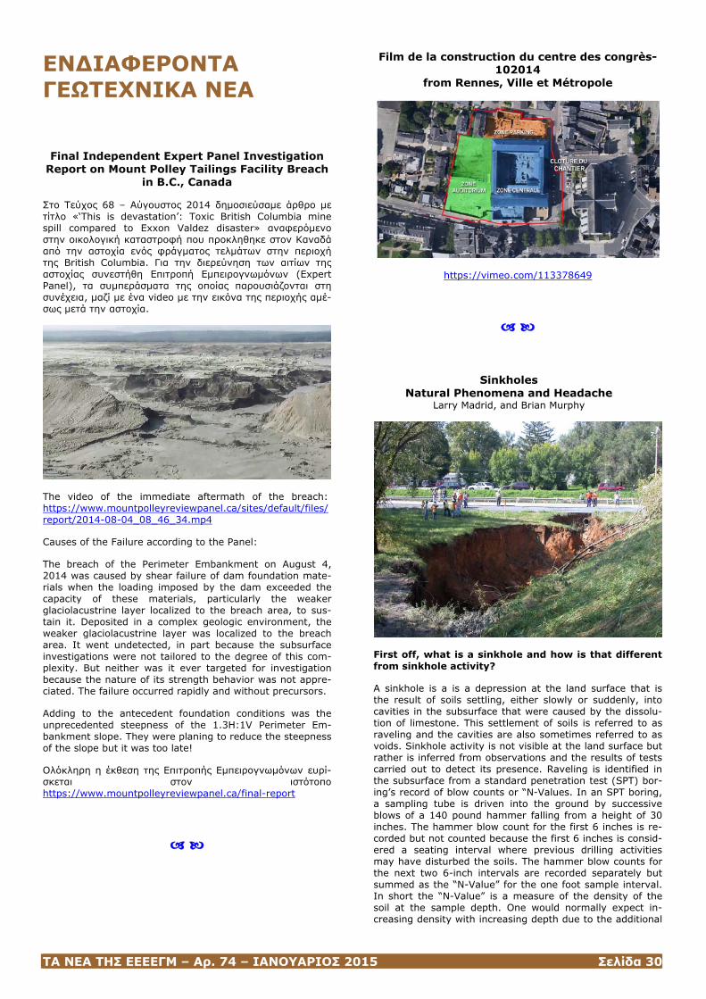
ΤΑ ΝΕΑ ΤΗΣ ΕΕΕΕΓΜ – Αρ. 74 – ΙΑΝΟΥΑΡΙΟΣ 2015 Σελίδα 30
ΕΝΔΙΑΦΕΡΟΝΤΑ ΓΕΩΤΕΧΝΙΚΑ ΝΕΑ
Final Independent Expert Panel Investigation
Report on Mount Polley Tailings Facility Breach in B.C., Canada
Στο Τεύχος 68 – Αύγουστος 2014 δημοσιεύσαμε άρθρο με τίτλο «‘This is devastation’: Toxic British Columbia mine spill compared to Exxon Valdez disaster» αναφερόμενο στην οικολογική καταστροφή που προκληθηκε στον Καναδά από την αστοχία ενός φράγματος τελμάτων στην περιοχή της British Columbia. Για την διερεύνηση των αιτίων της αστοχίας συνεστήθη Επιτροπή Εμπειρογνωμόνων (Expert Panel), τα συμπεράσματα της οποίας παρουσιάζονται στη συνέχεια, μαζί με ένα video με την εικόνα της περιοχής αμέ-σως μετά την αστοχία.
The video of the immediate aftermath of the breach: https://www.mountpolleyreviewpanel.ca/sites/default/files/report/2014-08-04_08_46_34.mp4
Causes of the Failure according to the Panel:
The breach of the Perimeter Embankment on August 4, 2014 was caused by shear failure of dam foundation mate-rials when the loading imposed by the dam exceeded the capacity of these materials, particularly the weaker glaciolacustrine layer localized to the breach area, to sus-tain it. Deposited in a complex geologic environment, the weaker glaciolacustrine layer was localized to the breach area. It went undetected, in part because the subsurface investigations were not tailored to the degree of this com-plexity. But neither was it ever targeted for investigation because the nature of its strength behavior was not appre-ciated. The failure occurred rapidly and without precursors.
Adding to the antecedent foundation conditions was the unprecedented steepness of the 1.3H:1V Perimeter Em-bankment slope. They were planing to reduce the steepness of the slope but it was too late!
Ολόκληρη η έκθεση της Επιτροπής Εμπειρογνωμόνων ευρί-σκεται στον ιστότοπο https://www.mountpolleyreviewpanel.ca/final-report
Film de la construction du centre des congrès-102014
from Rennes, Ville et Métropole
https://vimeo.com/113378649
Sinkholes Natural Phenomena and Headache
Larry Madrid, and Brian Murphy
First off, what is a sinkhole and how is that different from sinkhole activity?
A sinkhole is a is a depression at the land surface that is the result of soils settling, either slowly or suddenly, into cavities in the subsurface that were caused by the dissolu-tion of limestone. This settlement of soils is referred to as raveling and the cavities are also sometimes referred to as voids. Sinkhole activity is not visible at the land surface but rather is inferred from observations and the results of tests carried out to detect its presence. Raveling is identified in the subsurface from a standard penetration test (SPT) bor-ing’s record of blow counts or “N-Values. In an SPT boring, a sampling tube is driven into the ground by successive blows of a 140 pound hammer falling from a height of 30 inches. The hammer blow count for the first 6 inches is re-corded but not counted because the first 6 inches is consid-ered a seating interval where previous drilling activities may have disturbed the soils. The hammer blow counts for the next two 6-inch intervals are recorded separately but summed as the “N-Value” for the one foot sample interval. In short the “N-Value” is a measure of the density of the soil at the sample depth. One would normally expect in-creasing density with increasing depth due to the additional
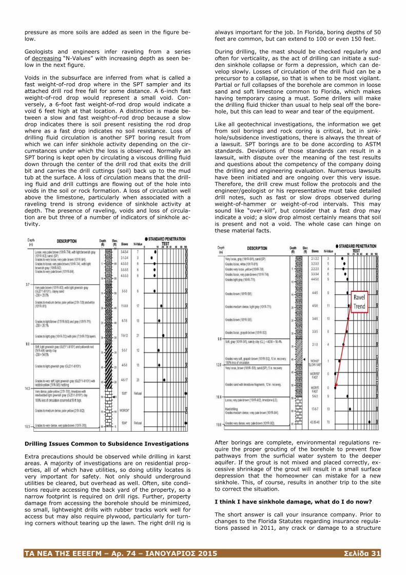
ΤΑ ΝΕΑ ΤΗΣ ΕΕΕΕΓΜ – Αρ. 74 – ΙΑΝΟΥΑΡΙΟΣ 2015 Σελίδα 31
pressure as more soils are added as seen in the figure be-low.
Geologists and engineers infer raveling from a series of decreasing “N-Values” with increasing depth as seen be-low in the next figure.
Voids in the subsurface are inferred from what is called a fast weight-of-rod drop where in the SPT sampler and its attached drill rod free fall for some distance. A 6-inch fast weight-of-rod drop would represent a small void. Con-versely, a 6-foot fast weight-of-rod drop would indicate a void 6 feet high at that location. A distinction is made be-tween a slow and fast weight-of-rod drop because a slow drop indicates there is soil present resisting the rod drop where as a fast drop indicates no soil resistance. Loss of drilling fluid circulation is another SPT boring result from which we can infer sinkhole activity depending on the cir-cumstances under which the loss is observed. Normally an SPT boring is kept open by circulating a viscous drilling fluid down through the center of the drill rod that exits the drill bit and carries the drill cuttings (soil) back up to the mud tub at the surface. A loss of circulation means that the drill-ing fluid and drill cuttings are flowing out of the hole into voids in the soil or rock formation. A loss of circulation well above the limestone, particularly when associated with a raveling trend is strong evidence of sinkhole activity at depth. The presence of raveling, voids and loss of circula-tion are but three of a number of indicators of sinkhole ac-tivity.
Drilling Issues Common to Subsidence Investigations
Extra precautions should be observed while drilling in karst areas. A majority of investigations are on residential prop-erties, all of which have utilities, so doing utility locates is very important for safety. Not only should underground utilities be cleared, but overhead as well. Often, site condi-tions require accessing the back yard of the property, so a narrow footprint is required on drill rigs. Further, property damage from accessing the borehole should be minimized, so small, lightweight drills with rubber tracks work well for access but may also require plywood, particularly for turn-ing corners without tearing up the lawn. The right drill rig is
always important for the job. In Florida, boring depths of 50 feet are common, but can extend to 100 or even 150 feet.
During drilling, the mast should be checked regularly and often for verticality, as the act of drilling can initiate a sud-den sinkhole collapse or form a depression, which can de-velop slowly. Losses of circulation of the drill fluid can be a precursor to a collapse, so that is when to be most vigilant. Partial or full collapses of the borehole are common in loose sand and soft limestone common to Florida, which makes having temporary casing a must. Some drillers will make the drilling fluid thicker than usual to help seal off the bore-hole, but this can lead to wear and tear of the equipment.
Like all geotechnical investigations, the information we get from soil borings and rock coring is critical, but in sink-hole/subsidence investigations, there is always the threat of a lawsuit. SPT borings are to be done according to ASTM standards. Deviations of those standards can result in a lawsuit, with dispute over the meaning of the test results and questions about the competency of the company doing the drilling and engineering evaluation. Numerous lawsuits have been initiated and are ongoing over this very issue. Therefore, the drill crew must follow the protocols and the engineer/geologist or his representative must take detailed drill notes, such as fast or slow drops observed during weight-of-hammer or weight-of-rod intervals. This may sound like “over-kill”, but consider that a fast drop may indicate a void; a slow drop almost certainly means that soil is present and not a void. The whole case can hinge on these material facts.
After borings are complete, environmental regulations re-quire the proper grouting of the borehole to prevent flow pathways from the surficial water system to the deeper aquifer. If the grout is not mixed and placed correctly, ex-cessive shrinkage of the grout will result in a small surface depression that the homeowner can mistake for a new sinkhole. This, of course, results in another trip to the site to correct the situation.
I think I have sinkhole damage, what do I do now?
The short answer is call your insurance company. Prior to changes to the Florida Statutes regarding insurance regula-tions passed in 2011, any crack or damage to a structure
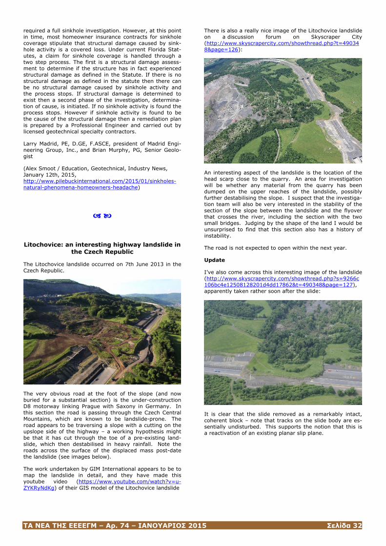
ΤΑ ΝΕΑ ΤΗΣ ΕΕΕΕΓΜ – Αρ. 74 – ΙΑΝΟΥΑΡΙΟΣ 2015 Σελίδα 32
required a full sinkhole investigation. However, at this point in time, most homeowner insurance contracts for sinkhole coverage stipulate that structural damage caused by sink-hole activity is a covered loss. Under current Florida Stat-utes, a claim for sinkhole coverage is handled through a two step process. The first is a structural damage assess-ment to determine if the structure has in fact experienced structural damage as defined in the Statute. If there is no structural damage as defined in the statute then there can be no structural damage caused by sinkhole activity and the process stops. If structural damage is determined to exist then a second phase of the investigation, determina-tion of cause, is initiated. If no sinkhole activity is found the process stops. However if sinkhole activity is found to be the cause of the structural damage then a remediation plan is prepared by a Professional Engineer and carried out by licensed geotechnical specialty contractors.
Larry Madrid, PE, D.GE, F.ASCE, president of Madrid Engi-neering Group, Inc., and Brian Murphy, PG, Senior Geolo-gist
(Alex Smoot / Education, Geotechnical, Industry News, January 12th, 2015, http://www.pilebuckinternational.com/2015/01/sinkholes-natural-phenomena-homeowners-headache)
Litochovice: an interesting highway landslide in the Czech Republic
The Litochovice landslide occurred on 7th June 2013 in the Czech Republic.
The very obvious road at the foot of the slope (and now buried for a substantial section) is the under-construction D8 motorway linking Prague with Saxony in Germany. In this section the road is passing through the Czech Central Mountains, which are known to be landslide-prone. The road appears to be traversing a slope with a cutting on the upslope side of the highway – a working hypothesis might be that it has cut through the toe of a pre-existing land-slide, which then destabilised in heavy rainfall. Note the roads across the surface of the displaced mass post-date the landslide (see images below).
The work undertaken by GIM International appears to be to map the landslide in detail, and they have made this youtube video (https://www.youtube.com/watch?v=u-ZYKRyNdKg) of their GIS model of the Litochovice landslide
There is also a really nice image of the Litochovice landslide on a discussion forum on Skyscraper City (http://www.skyscrapercity.com/showthread.php?t=490348&page=126):
An interesting aspect of the landslide is the location of the head scarp close to the quarry. An area for investigation will be whether any material from the quarry has been dumped on the upper reaches of the landslide, possibly further destabilising the slope. I suspect that the investiga-tion team will also be very interested in the stability of the section of the slope between the landslide and the flyover that crosses the river, including the section with the two small bridges. Judging by the shape of the land I would be unsurprised to find that this section also has a history of instability.
The road is not expected to open within the next year.
Update
I’ve also come across this interesting image of the landslide (http://www.skyscrapercity.com/showthread.php?s=9266c106bc4e12508128201d4dd17862&t=490348&page=127), apparently taken rather soon after the slide:
It is clear that the slide removed as a remarkably intact, coherent block – note that tracks on the slide body are es-sentially undisturbed. This supports the notion that this is a reactivation of an existing planar slip plane.
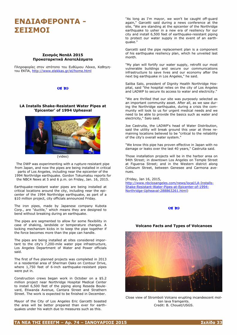
ΤΑ ΝΕΑ ΤΗΣ ΕΕΕΕΓΜ – Αρ. 74 – ΙΑΝΟΥΑΡΙΟΣ 2015 Σελίδα 33
ΕΝΔΙΑΦΕΡΟΝΤΑ - ΣΕΙΣΜΟΙ
Σεισμός Νεπάλ 2015 Προκαταρκτικά Αποτελέσματα
Πληροφορίες στον ιστότοπο του Ευθύμιου Λέκκα, Καθηγη-του ΕΚΠΑ, http://www.elekkas.gr/el/home.html
LA Installs Shake-Resistant Water Pipes at 'Epicenter' of 1994 Upheaval
(video)
The DWP was experimenting with a rupture-resistant pipe from Japan, and now the pipes are being installed in critical
parts of Los Angeles, including near the epicenter of the 1994 Northridge earthquake. Gordon Tokumatsu reports for the NBC4 News at 5 and 6 p.m. on Friday, Jan. 16, 2015.
Earthquake-resistant water pipes are being installed at critical locations around the city, including near the epi-center of the 1994 Northridge earthquake, as part of a $10 million project, city officials announced Friday.
The iron pipes, made by Japanese company Kubota Corp., are "ductile," which means they are designed to bend without breaking during an earthquake.
The pipes are segmented to allow for some flexibility in case of shaking, landslide or temperature changes. A locking mechanism kicks in to keep the pipe together if the force becomes more than the pipe can handle.
The pipes are being installed at sites considered impor-tant to the city's 7,200-mile water pipe infrastructure, Los Angeles Department of Water and Power officials said.
The first of five planned projects was completed in 2013 in a residential area of Sherman Oaks on Contour Drive, where 1,750 feet of 6-inch earthquake-resistant pipes were put in.
Construction crews began work in October on a $5.2 million project near Northridge Hospital Medical Center to install 6,500 feet of the piping along Reseda Boule-vard, Etiwanda Avenue, Cantara Street and Strathern Street. The work is expected to be finished in December.
Mayor of the City of Los Angeles Eric Garcetti boasted the area will be better prepared than ever for earth-quakes under his watch due to measures such as this.
"As long as I'm mayor, we won't be caught off-guard again," Garcetti said during a news conference at the site, "We are standing at the epicenter of the Northridge earthquake to usher in a new era of resiliency for our city and install 6,500 feet of earthquake-resistant piping to protect our water supply in the event of an earth-quake."
Garcetti said the pipe replacement plan is a component of his earthquake resiliency plan, which he unveiled last month.
"My plan will fortify our water supply, retrofit our most vulnerable buildings and secure our communications infrastructure to save lives and our economy after the next big earthquake in Los Angeles," he said.
Saliba Salo, president of Dignity Health Northridge Hos-pital, said "the hospital relies on the city of Los Angeles and LADWP to secure its access to water and electricity."
"We are thrilled that our site was purposely selected as an important community asset. After all, as we saw dur-ing the Northridge earthquake, during a crisis the com-munity will look to us for urgent medical needs and we need to be able to provide the basics such as water and electricity," Salo said.
Joe Castruita, the LADWP's head of Water Distribution, said the utility will break ground this year at three re-maining locations believed to be "critical to the reliability of the city's overall water system."
"We know this pipe has proven effective in Japan with no damage or leaks over the last 40 years," Castruita said.
Those installation projects will be in the harbor area on 94th Street; in downtown Los Angeles on Temple Street at Figueroa Street; and in the Western district along Coliseum Street, between Genesee and Carmona ave-nues.
(Friday, Jan 16, 2015, http://www.nbclosangeles.com/news/local/LA-Installs-Shake-Resistant-Water-Pipes-at-Epicenter-of-1994-Northridge-Upheaval-288863261.html)
Volcano Facts and Types of Volcanoes
Close view of Stromboli Volcano erupting incandescent mol-ten lava framgents.
Credit: B. Chouet/USGS.
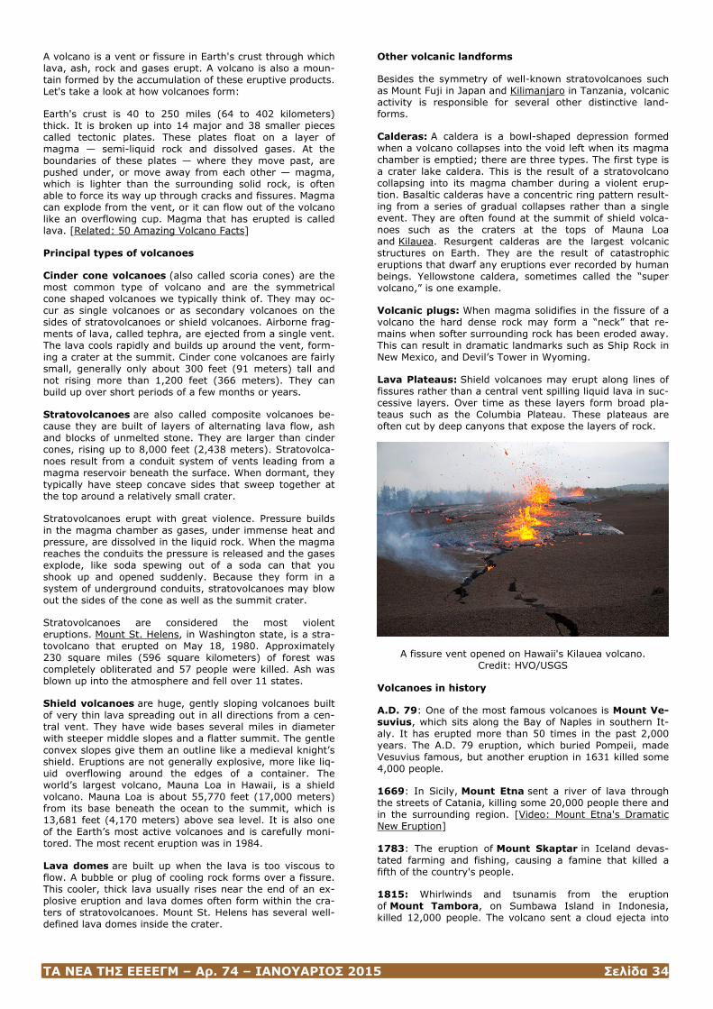
ΤΑ ΝΕΑ ΤΗΣ ΕΕΕΕΓΜ – Αρ. 74 – ΙΑΝΟΥΑΡΙΟΣ 2015 Σελίδα 34
A volcano is a vent or fissure in Earth's crust through which lava, ash, rock and gases erupt. A volcano is also a moun-tain formed by the accumulation of these eruptive products. Let's take a look at how volcanoes form:
Earth's crust is 40 to 250 miles (64 to 402 kilometers) thick. It is broken up into 14 major and 38 smaller pieces called tectonic plates. These plates float on a layer of magma — semi-liquid rock and dissolved gases. At the boundaries of these plates — where they move past, are pushed under, or move away from each other — magma, which is lighter than the surrounding solid rock, is often able to force its way up through cracks and fissures. Magma can explode from the vent, or it can flow out of the volcano like an overflowing cup. Magma that has erupted is called lava. [Related: 50 Amazing Volcano Facts]
Principal types of volcanoes
Cinder cone volcanoes (also called scoria cones) are the most common type of volcano and are the symmetrical cone shaped volcanoes we typically think of. They may oc-cur as single volcanoes or as secondary volcanoes on the sides of stratovolcanoes or shield volcanoes. Airborne frag-ments of lava, called tephra, are ejected from a single vent. The lava cools rapidly and builds up around the vent, form-ing a crater at the summit. Cinder cone volcanoes are fairly small, generally only about 300 feet (91 meters) tall and not rising more than 1,200 feet (366 meters). They can build up over short periods of a few months or years.
Stratovolcanoes are also called composite volcanoes be-cause they are built of layers of alternating lava flow, ash and blocks of unmelted stone. They are larger than cinder cones, rising up to 8,000 feet (2,438 meters). Stratovolca-noes result from a conduit system of vents leading from a magma reservoir beneath the surface. When dormant, they typically have steep concave sides that sweep together at the top around a relatively small crater.
Stratovolcanoes erupt with great violence. Pressure builds in the magma chamber as gases, under immense heat and pressure, are dissolved in the liquid rock. When the magma reaches the conduits the pressure is released and the gases explode, like soda spewing out of a soda can that you shook up and opened suddenly. Because they form in a system of underground conduits, stratovolcanoes may blow out the sides of the cone as well as the summit crater.
Stratovolcanoes are considered the most violent eruptions. Mount St. Helens, in Washington state, is a stra-tovolcano that erupted on May 18, 1980. Approximately 230 square miles (596 square kilometers) of forest was completely obliterated and 57 people were killed. Ash was blown up into the atmosphere and fell over 11 states.
Shield volcanoes are huge, gently sloping volcanoes built of very thin lava spreading out in all directions from a cen-tral vent. They have wide bases several miles in diameter with steeper middle slopes and a flatter summit. The gentle convex slopes give them an outline like a medieval knight’s shield. Eruptions are not generally explosive, more like liq-uid overflowing around the edges of a container. The world’s largest volcano, Mauna Loa in Hawaii, is a shield volcano. Mauna Loa is about 55,770 feet (17,000 meters) from its base beneath the ocean to the summit, which is 13,681 feet (4,170 meters) above sea level. It is also one of the Earth’s most active volcanoes and is carefully moni-tored. The most recent eruption was in 1984.
Lava domes are built up when the lava is too viscous to flow. A bubble or plug of cooling rock forms over a fissure. This cooler, thick lava usually rises near the end of an ex-plosive eruption and lava domes often form within the cra-ters of stratovolcanoes. Mount St. Helens has several well-defined lava domes inside the crater.
Other volcanic landforms
Besides the symmetry of well-known stratovolcanoes such as Mount Fuji in Japan and Kilimanjaro in Tanzania, volcanic activity is responsible for several other distinctive land-forms.
Calderas: A caldera is a bowl-shaped depression formed when a volcano collapses into the void left when its magma chamber is emptied; there are three types. The first type is a crater lake caldera. This is the result of a stratovolcano collapsing into its magma chamber during a violent erup-tion. Basaltic calderas have a concentric ring pattern result-ing from a series of gradual collapses rather than a single event. They are often found at the summit of shield volca-noes such as the craters at the tops of Mauna Loa and Kilauea. Resurgent calderas are the largest volcanic structures on Earth. They are the result of catastrophic eruptions that dwarf any eruptions ever recorded by human beings. Yellowstone caldera, sometimes called the “super volcano,” is one example.
Volcanic plugs: When magma solidifies in the fissure of a volcano the hard dense rock may form a “neck” that re-mains when softer surrounding rock has been eroded away. This can result in dramatic landmarks such as Ship Rock in New Mexico, and Devil’s Tower in Wyoming.
Lava Plateaus: Shield volcanoes may erupt along lines of fissures rather than a central vent spilling liquid lava in suc-cessive layers. Over time as these layers form broad pla-teaus such as the Columbia Plateau. These plateaus are often cut by deep canyons that expose the layers of rock.
A fissure vent opened on Hawaii's Kilauea volcano. Credit: HVO/USGS
Volcanoes in history
A.D. 79: One of the most famous volcanoes is Mount Ve-suvius, which sits along the Bay of Naples in southern It-aly. It has erupted more than 50 times in the past 2,000 years. The A.D. 79 eruption, which buried Pompeii, made Vesuvius famous, but another eruption in 1631 killed some 4,000 people.
1669: In Sicily, Mount Etna sent a river of lava through the streets of Catania, killing some 20,000 people there and in the surrounding region. [Video: Mount Etna's Dramatic New Eruption]
1783: The eruption of Mount Skaptar in Iceland devas-tated farming and fishing, causing a famine that killed a fifth of the country's people.
1815: Whirlwinds and tsunamis from the eruption of Mount Tambora, on Sumbawa Island in Indonesia, killed 12,000 people. The volcano sent a cloud ejecta into

ΤΑ ΝΕΑ ΤΗΣ ΕΕΕΕΓΜ – Αρ. 74 – ΙΑΝΟΥΑΡΙΟΣ 2015 Σελίδα 35
the atmosphere that was more than four times the amount ejected by Mount Pinatubo in 1991.
1883: Another Indonesian volcano, Krakatoa, erupted in an explosion heard 3,000 miles away. Seventy-pound boul-ders landed on islands 50 miles away, and a 130-foot tsu-nami devastated hundreds of villages, including Java and Sumatra. About 36,000 people died. Dust high in the at-mosphere caused the Moon to appear blue, and sometimes green, for two years.
1902: Mount Pelée, on the island of Martinique, smoth-ered the town of Saint-Pierre in deadly gas and hot ash, killing 29,933 of the 29,937 residents.
1980: Mount St. Helens in Washington state blew 1,300 feet off its top, killing 57 people and causing a midday darkness in towns 85 miles away.
1991: After 600 years of dormancy, Mount Pinatubo in the Philippines rumbled for days before erupting and killing about 750 people. Ash was more than 6 feet deep in a two-mile radius around the volcano, and buried a U.S. air base 15 miles away.
Pinatubo's cloud of sulfuric acid, some 20 million tons of it, climbed to more than 12 miles in the stratosphere. Over the next several weeks, the cloud encircled the equator and spread to the poles, covering the entire planet. The parti-cles reflected sunlight and cooled the Earth by nearly a full degree Fahrenheit.
Other significant U.S. volcanoes
Lassen Peak, California: Erupted between 1914 and 1917, causing no deaths. Lassen is considered one of the most likely in the Cascade Range to erupt again.
Long Valley, California: The Long Valley Caldera is a 10-by 20-mile depression in the Sierra Nevada Mountains caused by an eruption 700,000 years ago. A tremendous explosion spit out molten rock from 4 miles under the sur-face; afterward, the whole mess settled more than a mile down into the depression where the magma had been.
Magma still feeds hot springs in the caldera. Earthquakes in 1980 marked the beginning of new activity that has in-cluded shifts in the position of hot springs and swarms of other small earthquakes. Geologists say it probably indi-cates that magma is again rising from below, and they sus-pect the area will erupt again.
Mount Shasta, California: Last known eruption was in 1786. It is believed to erupt every 600 to 800 years. Moun-tain is significant as the incredibly dominant visual element in the Northern California landscape.
Kilauea and Muana Loa, Hawaii: Each tends to erupt every two or three years; eruptions are non-explosive, al-lowing these two volcanoes to be among the most studied active volcanoes in the world.
http://www.livescience.com/27295-volcanoes.html
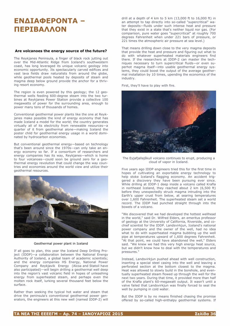
ΤΑ ΝΕΑ ΤΗΣ ΕΕΕΕΓΜ – Αρ. 74 – ΙΑΝΟΥΑΡΙΟΣ 2015 Σελίδα 36
ΕΝΔΙΑΦΕΡΟΝΤΑ – ΠΕΡΙΒΑΛΛΟΝ
Are volcanoes the energy source of the future?
The Reykjanes Peninsula, a finger of black rock jutting out over the Mid-Atlantic Ridge from Iceland's southwestern coast, has long leveraged its unique volcanic geology into economic opportunity. Its spectacularly carved edifices and vast lava fields draw naturalists from around the globe, while geothermal pools heated by deposits of steam and magma deep below ground provide the anchor for a thriv-ing resort economy.
The region is even powered by this geology; the 12 geo-thermal wells feeding 600-degree steam into the two tur-bines at Reykjanes Power Station provide a collective 100 megawatts of power for the surrounding area, enough to power many tens of thousands of homes.
Conventional geothermal power plants like the one at Reyk-janes make possible the kind of energy economy that has made Iceland a model for the world; the country generates virtually all of its electricity from renewable resources—a quarter of it from geothermal alone—making Iceland the poster child for geothermal energy usage in a world domi-nated by hydrocarbon economies.
But conventional geothermal energy—based on technology that's been around since the 1970s—can only take an en-ergy economy so far. If a consortium of researchers and energy companies has its way, Reykjanes—which is home to four volcanoes—could soon be ground zero for a geo-thermal energy revolution that could change the way coun-tries and economies around the world view and utilize their geothermal resources.
Geothermal power plant in Iceland
If all goes to plan, this year the Iceland Deep Drilling Pro-ject (IDDP)—a collaboration between the National Energy Authority of Iceland, a global team of academic scientists; and the energy companies HS Energy, National Power Company and Reykjavik Energy (Alcoa and Statoil have also participated)—will begin drilling a geothermal well deep into the region's vast volcanic field in hopes of unleashing energy from superheated steam, and perhaps even the molten rock itself, lurking several thousand feet below the surface.
Rather than seeking the typical hot water and steam that drive the peninsula's conventional geothermal power gen-erators, the engineers at this new well (named IDDP-2) will
drill at a depth of 4 km to 5 km (13,000 ft to 16,000 ft) in an attempt to tap directly into so-called "supercritical" wa-ter deposits—fluids under such intense heat and pressure that they exist in a state that's neither liquid nor gas. (For comparison, pure water goes "supercritical" at roughly 700 degrees Fahrenheit when under 221 bars of pressure, or 221 times the atmospheric air pressure at sea level.)
That means drilling down close to the very magma deposits that provide the heat and pressure and figuring out what to do with whatever superheated materials engineers find there. If the researchers at IDDP-2 can master the tech-niques necessary to turn supercritical fluids—or even su-perhot magma itself—into usable geothermal energy sys-tems, they could boost the output of the average geother-mal installation by 10 times, upending the economics of the industry.
First, they'll have to play with fire.
The Eyjafjallajškull volcano continues to erupt, producing a cloud of vapor in Iceland.
Five years ago IDDP engineers tried this for the first time in hopes of cultivating an exportable energy technology to help stoke Iceland's flagging economy. An accident trig-gered a discovery they have been pursuing ever since. While drilling at IDDP-1 deep inside a volcano called Krafla in northeast Iceland, they reached about 2 km (6,500 ft) before they unexpectedly struck magma intruding into the Earth's upper crust from below, at searing temperatures over 1,600 Fahrenheit. The superheated steam set a world record. The IDDP had punched straight through into the bowels of a volcano.
"We discovered that we had developed the hottest wellhead in the world," said Dr. Wilfred Elders, an emeritus professor of geology at the University of California, Riverside, and co-chief scientist for the IDDP. Landsvirkjun, Iceland's national power company and the owner of the well, had no idea what to do with superheated magma bubbling up the well pipe at temperatures upward of 1,600 degrees Fahrenheit. "At that point, we could have abandoned the well," Elders said. "We knew we had this very high energy heat source, but we didn't know how to deal with the temperatures and pressures."
Instead, Landsvirkjun pushed ahead with well construction, inserting a special steel casing into the well and leaving a perforated section at the bottom closest to the magma. Heat was allowed to slowly build in the borehole, and even-tually superheated steam flowed up through the well for the next two years. During that time, it provided more than half of the Krafla plant's 60-megawatt output. It wasn't until a valve failed that Landsvirkjun was finally forced to seal the well by pumping in cold water.
But the IDDP is by no means finished chasing the promise offered by so-called high-enthalpy geothermal systems. If
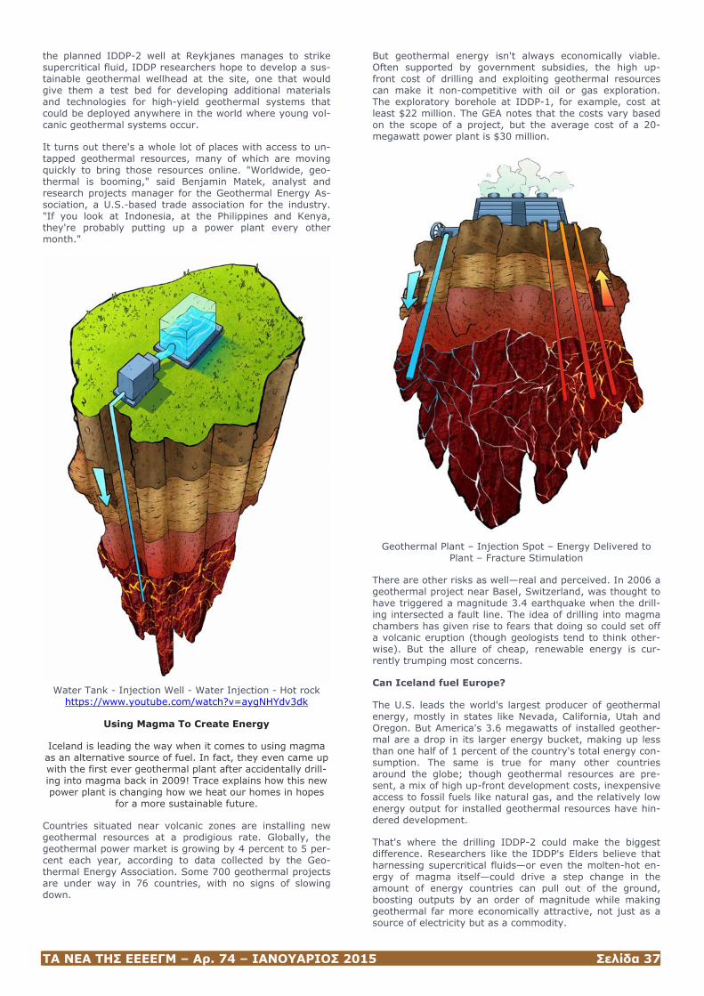
ΤΑ ΝΕΑ ΤΗΣ ΕΕΕΕΓΜ – Αρ. 74 – ΙΑΝΟΥΑΡΙΟΣ 2015 Σελίδα 37
the planned IDDP-2 well at Reykjanes manages to strike supercritical fluid, IDDP researchers hope to develop a sus-tainable geothermal wellhead at the site, one that would give them a test bed for developing additional materials and technologies for high-yield geothermal systems that could be deployed anywhere in the world where young vol-canic geothermal systems occur.
It turns out there's a whole lot of places with access to un-tapped geothermal resources, many of which are moving quickly to bring those resources online. "Worldwide, geo-thermal is booming," said Benjamin Matek, analyst and research projects manager for the Geothermal Energy As-sociation, a U.S.-based trade association for the industry. "If you look at Indonesia, at the Philippines and Kenya, they're probably putting up a power plant every other month."
Water Tank - Injection Well - Water Injection - Hot rock
https://www.youtube.com/watch?v=aygNHYdv3dk
Using Magma To Create Energy
Iceland is leading the way when it comes to using magma as an alternative source of fuel. In fact, they even came up with the first ever geothermal plant after accidentally drill-ing into magma back in 2009! Trace explains how this new power plant is changing how we heat our homes in hopes
for a more sustainable future.
Countries situated near volcanic zones are installing new geothermal resources at a prodigious rate. Globally, the geothermal power market is growing by 4 percent to 5 per-cent each year, according to data collected by the Geo-thermal Energy Association. Some 700 geothermal projects are under way in 76 countries, with no signs of slowing down.
But geothermal energy isn't always economically viable. Often supported by government subsidies, the high up-front cost of drilling and exploiting geothermal resources can make it non-competitive with oil or gas exploration. The exploratory borehole at IDDP-1, for example, cost at least $22 million. The GEA notes that the costs vary based on the scope of a project, but the average cost of a 20-megawatt power plant is $30 million.
Geothermal Plant – Injection Spot – Energy Delivered to Plant – Fracture Stimulation
There are other risks as well—real and perceived. In 2006 a geothermal project near Basel, Switzerland, was thought to have triggered a magnitude 3.4 earthquake when the drill-ing intersected a fault line. The idea of drilling into magma chambers has given rise to fears that doing so could set off a volcanic eruption (though geologists tend to think other-wise). But the allure of cheap, renewable energy is cur-rently trumping most concerns.
Can Iceland fuel Europe?
The U.S. leads the world's largest producer of geothermal energy, mostly in states like Nevada, California, Utah and Oregon. But America's 3.6 megawatts of installed geother-mal are a drop in its larger energy bucket, making up less than one half of 1 percent of the country's total energy con-sumption. The same is true for many other countries around the globe; though geothermal resources are pre-sent, a mix of high up-front development costs, inexpensive access to fossil fuels like natural gas, and the relatively low energy output for installed geothermal resources have hin-dered development.
That's where the drilling IDDP-2 could make the biggest difference. Researchers like the IDDP's Elders believe that harnessing supercritical fluids—or even the molten-hot en-ergy of magma itself—could drive a step change in the amount of energy countries can pull out of the ground, boosting outputs by an order of magnitude while making geothermal far more economically attractive, not just as a source of electricity but as a commodity.
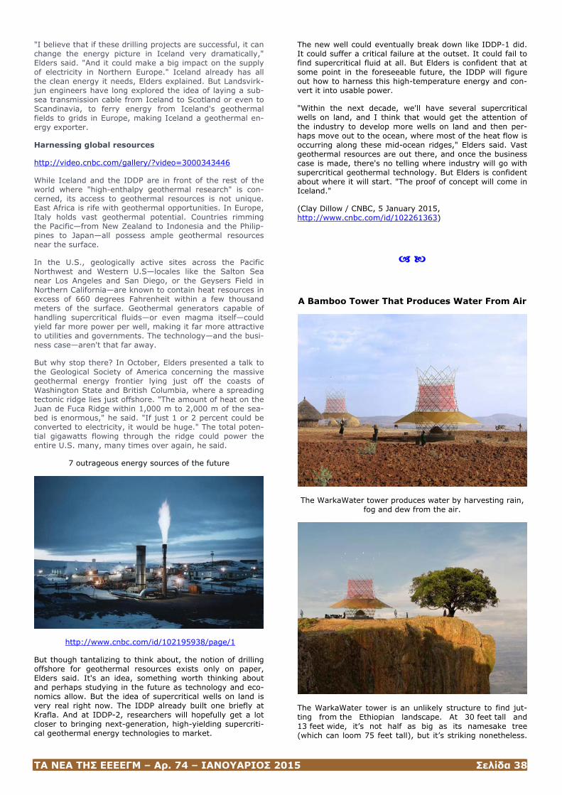
ΤΑ ΝΕΑ ΤΗΣ ΕΕΕΕΓΜ – Αρ. 74 – ΙΑΝΟΥΑΡΙΟΣ 2015 Σελίδα 38
"I believe that if these drilling projects are successful, it can change the energy picture in Iceland very dramatically," Elders said. "And it could make a big impact on the supply of electricity in Northern Europe." Iceland already has all the clean energy it needs, Elders explained. But Landsvirk-jun engineers have long explored the idea of laying a sub-sea transmission cable from Iceland to Scotland or even to Scandinavia, to ferry energy from Iceland's geothermal fields to grids in Europe, making Iceland a geothermal en-ergy exporter.
Harnessing global resources
http://video.cnbc.com/gallery/?video=3000343446
While Iceland and the IDDP are in front of the rest of the world where "high-enthalpy geothermal research" is con-cerned, its access to geothermal resources is not unique. East Africa is rife with geothermal opportunities. In Europe, Italy holds vast geothermal potential. Countries rimming the Pacific—from New Zealand to Indonesia and the Philip-pines to Japan—all possess ample geothermal resources near the surface.
In the U.S., geologically active sites across the Pacific Northwest and Western U.S—locales like the Salton Sea near Los Angeles and San Diego, or the Geysers Field in Northern California—are known to contain heat resources in excess of 660 degrees Fahrenheit within a few thousand meters of the surface. Geothermal generators capable of handling supercritical fluids—or even magma itself—could yield far more power per well, making it far more attractive to utilities and governments. The technology—and the busi-ness case—aren't that far away.
But why stop there? In October, Elders presented a talk to the Geological Society of America concerning the massive geothermal energy frontier lying just off the coasts of Washington State and British Columbia, where a spreading tectonic ridge lies just offshore. "The amount of heat on the Juan de Fuca Ridge within 1,000 m to 2,000 m of the sea-bed is enormous," he said. "If just 1 or 2 percent could be converted to electricity, it would be huge." The total poten-tial gigawatts flowing through the ridge could power the entire U.S. many, many times over again, he said.
7 outrageous energy sources of the future
http://www.cnbc.com/id/102195938/page/1
But though tantalizing to think about, the notion of drilling offshore for geothermal resources exists only on paper, Elders said. It's an idea, something worth thinking about and perhaps studying in the future as technology and eco-nomics allow. But the idea of supercritical wells on land is very real right now. The IDDP already built one briefly at Krafla. And at IDDP-2, researchers will hopefully get a lot closer to bringing next-generation, high-yielding supercriti-cal geothermal energy technologies to market.
The new well could eventually break down like IDDP-1 did. It could suffer a critical failure at the outset. It could fail to find supercritical fluid at all. But Elders is confident that at some point in the foreseeable future, the IDDP will figure out how to harness this high-temperature energy and con-vert it into usable power.
"Within the next decade, we'll have several supercritical wells on land, and I think that would get the attention of the industry to develop more wells on land and then per-haps move out to the ocean, where most of the heat flow is occurring along these mid-ocean ridges," Elders said. Vast geothermal resources are out there, and once the business case is made, there's no telling where industry will go with supercritical geothermal technology. But Elders is confident about where it will start. "The proof of concept will come in Iceland."
(Clay Dillow / CNBC, 5 January 2015, http://www.cnbc.com/id/102261363)
A Bamboo Tower That Produces Water From Air
The WarkaWater tower produces water by harvesting rain, fog and dew from the air.
The WarkaWater tower is an unlikely structure to find jut-ting from the Ethiopian landscape. At 30 feet tall and 13 feet wide, it’s not half as big as its namesake tree (which can loom 75 feet tall), but it’s striking nonetheless.
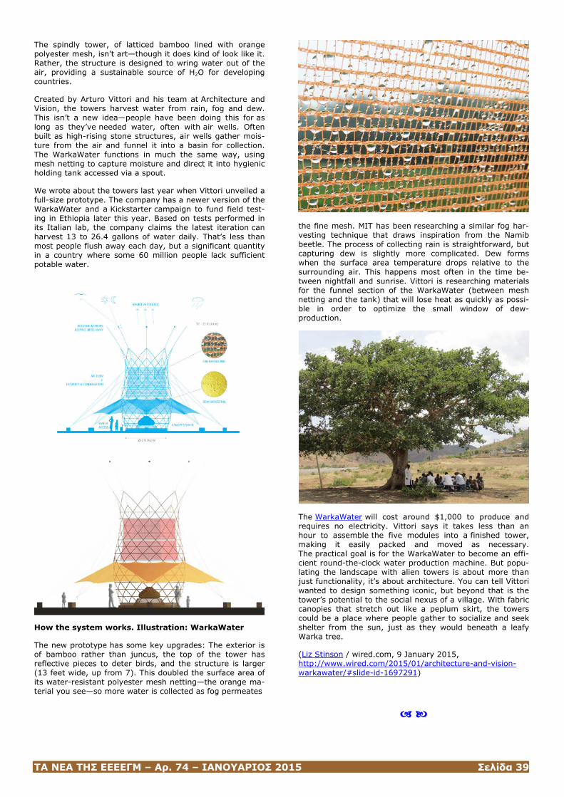
ΤΑ ΝΕΑ ΤΗΣ ΕΕΕΕΓΜ – Αρ. 74 – ΙΑΝΟΥΑΡΙΟΣ 2015 Σελίδα 39
The spindly tower, of latticed bamboo lined with orange polyester mesh, isn’t art—though it does kind of look like it. Rather, the structure is designed to wring water out of the air, providing a sustainable source of H2O for developing countries.
Created by Arturo Vittori and his team at Architecture and Vision, the towers harvest water from rain, fog and dew. This isn’t a new idea—people have been doing this for as long as they’ve needed water, often with air wells. Often built as high-rising stone structures, air wells gather mois-ture from the air and funnel it into a basin for collection. The WarkaWater functions in much the same way, using mesh netting to capture moisture and direct it into hygienic holding tank accessed via a spout.
We wrote about the towers last year when Vittori unveiled a full-size prototype. The company has a newer version of the WarkaWater and a Kickstarter campaign to fund field test-ing in Ethiopia later this year. Based on tests performed in its Italian lab, the company claims the latest iteration can harvest 13 to 26.4 gallons of water daily. That’s less than most people flush away each day, but a significant quantity in a country where some 60 million people lack sufficient potable water.
How the system works. Illustration: WarkaWater
The new prototype has some key upgrades: The exterior is of bamboo rather than juncus, the top of the tower has reflective pieces to deter birds, and the structure is larger (13 feet wide, up from 7). This doubled the surface area of its water-resistant polyester mesh netting—the orange ma-terial you see—so more water is collected as fog permeates
the fine mesh. MIT has been researching a similar fog har-vesting technique that draws inspiration from the Namib beetle. The process of collecting rain is straightforward, but capturing dew is slightly more complicated. Dew forms when the surface area temperature drops relative to the surrounding air. This happens most often in the time be-tween nightfall and sunrise. Vittori is researching materials for the funnel section of the WarkaWater (between mesh netting and the tank) that will lose heat as quickly as possi-ble in order to optimize the small window of dew-production.
The WarkaWater will cost around $1,000 to produce and requires no electricity. Vittori says it takes less than an hour to assemble the five modules into a finished tower, making it easily packed and moved as necessary. The practical goal is for the WarkaWater to become an effi-cient round-the-clock water production machine. But popu-lating the landscape with alien towers is about more than just functionality, it’s about architecture. You can tell Vittori wanted to design something iconic, but beyond that is the tower’s potential to the social nexus of a village. With fabric canopies that stretch out like a peplum skirt, the towers could be a place where people gather to socialize and seek shelter from the sun, just as they would beneath a leafy Warka tree.
(Liz Stinson / wired.com, 9 January 2015, http://www.wired.com/2015/01/architecture-and-vision-warkawater/#slide-id-1697291)
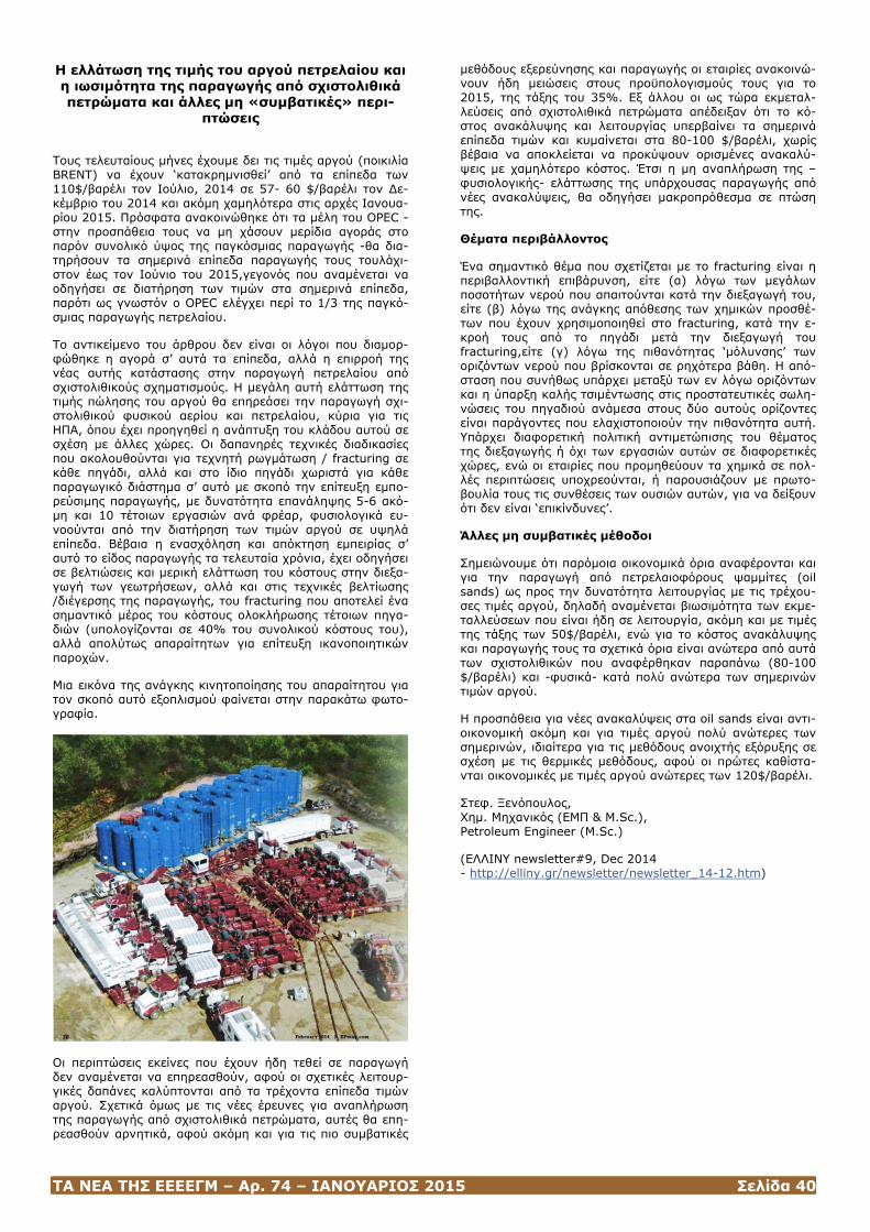
ΤΑ ΝΕΑ ΤΗΣ ΕΕΕΕΓΜ – Αρ. 74 – ΙΑΝΟΥΑΡΙΟΣ 2015 Σελίδα 40
Η ελλάτωση της τιμής του αργού πετρελαίου και η ιωσιμότητα της παραγωγής από σχιστολιθικά πετρώματα και άλλες μη «συμβατικές» περι-
πτώσεις
Τους τελευταίους μήνες έχουμε δει τις τιμές αργού (ποικιλία ΒRΕΝΤ) να έχουν ‘κατακρημνισθεί’ από τα επίπεδα των 110$/βαρέλι τον Ιούλιο, 2014 σε 57- 60 $/βαρέλι τον Δε-κέμβριο του 2014 και ακόμη χαμηλότερα στις αρχές Ιανουα-ρίου 2015. Πρόσφατα ανακοινώθηκε ότι τα μέλη του OPEC -στην προσπάθεια τους να μη χάσουν μερίδια αγοράς στο παρόν συνολικό ύψος της παγκόσμιας παραγωγής -θα δια-τηρήσουν τα σημερινά επίπεδα παραγωγής τους τουλάχι-στον έως τον Ιούνιο του 2015,γεγονός που αναμένεται να οδηγήσει σε διατήρηση των τιμών στα σημερινά επίπεδα, παρότι ως γνωστόν ο OPEC ελέγχει περί το 1/3 της παγκό-σμιας παραγωγής πετρελαίου.
Το αντικείμενο του άρθρου δεν είναι οι λόγοι που διαμορ-φώθηκε η αγορά σ’ αυτά τα επίπεδα, αλλά η επιρροή της νέας αυτής κατάστασης στην παραγωγή πετρελαίου από σχιστολιθικούς σχηματισμούς. Η μεγάλη αυτή ελάττωση της τιμής πώλησης του αργού θα επηρεάσει την παραγωγή σχι-στολιθικού φυσικού αερίου και πετρελαίου, κύρια για τις ΗΠΑ, όπου έχει προηγηθεί η ανάπτυξη του κλάδου αυτού σε σχέση με άλλες χώρες. Οι δαπανηρές τεχνικές διαδικασίες που ακολουθούνται για τεχνητή ρωγμάτωση / fracturing σε κάθε πηγάδι, αλλά και στο ίδιο πηγάδι χωριστά για κάθε παραγωγικό διάστημα σ’ αυτό με σκοπό την επίτευξη εμπο-ρεύσιμης παραγωγής, με δυνατότητα επανάληψης 5-6 ακό-μη και 10 τέτοιων εργασιών ανά φρέαρ, φυσιολογικά ευ-νοούνται από την διατήρηση των τιμών αργού σε υψηλά επίπεδα. Βέβαια η ενασχόληση και απόκτηση εμπειρίας σ’ αυτό το είδος παραγωγής τα τελευταία χρόνια, έχει οδηγήσει σε βελτιώσεις και μερική ελάττωση του κόστους στην διεξα-γωγή των γεωτρήσεων, αλλά και στις τεχνικές βελτίωσης /διέγερσης της παραγωγής, του fracturing που αποτελεί ένα σημαντικό μέρος του κόστους ολοκλήρωσης τέτοιων πηγα-διών (υπολογίζονται σε 40% του συνολικού κόστους του), αλλά απολύτως απαραίτητων για επίτευξη ικανοποιητικών παροχών.
Μια εικόνα της ανάγκης κινητοποίησης του απαραίτητου για τον σκοπό αυτό εξοπλισμού φαίνεται στην παρακάτω φωτο-γραφία.
Οι περιπτώσεις εκείνες που έχουν ήδη τεθεί σε παραγωγή δεν αναμένεται να επηρεασθούν, αφού οι σχετικές λειτουρ-γικές δαπάνες καλύπτονται από τα τρέχοντα επίπεδα τιμών αργού. Σχετικά όμως με τις νέες έρευνες για αναπλήρωση της παραγωγής από σχιστολιθικά πετρώματα, αυτές θα επη-ρεασθούν αρνητικά, αφού ακόμη και για τις πιο συμβατικές
μεθόδους εξερεύνησης και παραγωγής οι εταιρίες ανακοινώ-νουν ήδη μειώσεις στους προϋπολογισμούς τους για το 2015, της τάξης του 35%. Εξ άλλου οι ως τώρα εκμεταλ-λεύσεις από σχιστολιθικά πετρώματα απέδειξαν ότι το κό-στος ανακάλυψης και λειτουργίας υπερβαίνει τα σημερινά επίπεδα τιμών και κυμαίνεται στα 80-100 $/βαρέλι, χωρίς βέβαια να αποκλείεται να προκύψουν ορισμένες ανακαλύ-ψεις με χαμηλότερο κόστος. Έτσι η μη αναπλήρωση της –φυσιολογικής- ελάττωσης της υπάρχουσας παραγωγής από νέες ανακαλύψεις, θα οδηγήσει μακροπρόθεσμα σε πτώση της.
Θέματα περιβάλλοντος
Ένα σημαντικό θέμα που σχετίζεται με το fracturing είναι η περιβαλλοντική επιβάρυνση, είτε (α) λόγω των μεγάλων ποσοτήτων νερού που απαιτούνται κατά την διεξαγωγή του, είτε (β) λόγω της ανάγκης απόθεσης των χημικών προσθέ-των που έχουν χρησιμοποιηθεί στο fracturing, κατά την ε-κροή τους από το πηγάδι μετά την διεξαγωγή του fracturing,είτε (γ) λόγω της πιθανότητας ‘μόλυνσης’ των οριζόντων νερού που βρίσκονται σε ρηχότερα βάθη. Η από-σταση που συνήθως υπάρχει μεταξύ των εν λόγω οριζόντων και η ύπαρξη καλής τσιμέντωσης στις προστατευτικές σωλη-νώσεις του πηγαδιού ανάμεσα στους δύο αυτούς ορίζοντες είναι παράγοντες που ελαχιστοποιούν την πιθανότητα αυτή. Υπάρχει διαφορετική πολιτική αντιμετώπισης του θέματος της διεξαγωγής ή όχι των εργασιών αυτών σε διαφορετικές χώρες, ενώ οι εταιρίες που προμηθεύουν τα χημικά σε πολ-λές περιπτώσεις υποχρεούνται, ή παρουσιάζουν με πρωτο-βουλία τους τις συνθέσεις των ουσιών αυτών, για να δείξουν ότι δεν είναι ‘επικίνδυνες’.
Άλλες μη συμβατικές μέθοδοι
Σημειώνουμε ότι παρόμοια οικονομικά όρια αναφέρονται και για την παραγωγή από πετρελαιοφόρους ψαμμίτες (oil sands) ως προς την δυνατότητα λειτουργίας με τις τρέχου-σες τιμές αργού, δηλαδή αναμένεται βιωσιμότητα των εκμε-ταλλεύσεων που είναι ήδη σε λειτουργία, ακόμη και με τιμές της τάξης των 50$/βαρέλι, ενώ για το κόστος ανακάλυψης και παραγωγής τους τα σχετικά όρια είναι ανώτερα από αυτά των σχιστολιθικών που αναφέρθηκαν παραπάνω (80-100 $/βαρέλι) και -φυσικά- κατά πολύ ανώτερα των σημερινών τιμών αργού.
Η προσπάθεια για νέες ανακαλύψεις στα oil sands είναι αντι-οικονομική ακόμη και για τιμές αργού πολύ ανώτερες των σημερινών, ιδιαίτερα για τις μεθόδους ανοιχτής εξόρυξης σε σχέση με τις θερμικές μεθόδους, αφού οι πρώτες καθίστα-νται οικονομικές με τιμές αργού ανώτερες των 120$/βαρέλι.
Στεφ. Ξενόπουλος, Χημ. Μηχανικός (ΕΜΠ & M.Sc.), Petroleum Engineer (M.Sc.)
(ΕΛΛΙΝΥ newsletter#9, Dec 2014 - http://elliny.gr/newsletter/newsletter_14-12.htm)

ΤΑ ΝΕΑ ΤΗΣ ΕΕΕΕΓΜ – Αρ. 74 – ΙΑΝΟΥΑΡΙΟΣ 2015 Σελίδα 41
ΕΝΔΙΑΦΕΡΟΝΤΑ - ΛΟΙΠΑ
Amazing Feats of Engineering!
From incredibly designed bridges to elevators for boats - one of the most redeeming quality about man is his ability to solve problems by inventing new answers!
ΤΑ ΝΕΑ ΤΗΣ ΕΕΕΕΓΜ – Αρ. 74 – ΙΑΝΟΥΑΡΙΟΣ 2015 Σελίδα 42
The Tallest Bridge in The World
The Millau Viaduct bridge is the tallest bridge in the world with one mast's summit at 343.0 metres (1,125 ft) above the base of the structure. It is the 12th highest bridge deck in the world, being 270 metres (890 ft) between the road deck and the ground below. Millau Viaduct is part of the A75-A71 autoroute axis from Paris to Montpellier. Construc-tion cost was approximately €400 million. It was formally inaugurated on 14 December 2004, and opened to traffic on 16 December. The bridge has been consistently ranked as one of the great engineering achievements of all time. The bridge received the 2006 International Association for
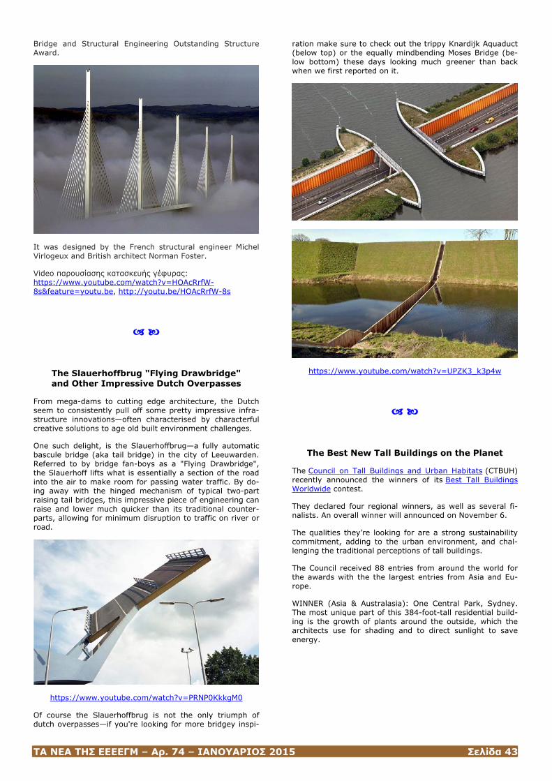
ΤΑ ΝΕΑ ΤΗΣ ΕΕΕΕΓΜ – Αρ. 74 – ΙΑΝΟΥΑΡΙΟΣ 2015 Σελίδα 43
Bridge and Structural Engineering Outstanding Structure Award.
It was designed by the French structural engineer Michel Virlogeux and British architect Norman Foster.
Video παρουσίασης κατασκευής γέφυρας: https://www.youtube.com/watch?v=HOAcRrfW-8s&feature=youtu.be, http://youtu.be/HOAcRrfW-8s
The Slauerhoffbrug "Flying Drawbridge" and Other Impressive Dutch Overpasses
From mega-dams to cutting edge architecture, the Dutch seem to consistently pull off some pretty impressive infra-structure innovations—often characterised by characterful creative solutions to age old built environment challenges.
One such delight, is the Slauerhoffbrug—a fully automatic bascule bridge (aka tail bridge) in the city of Leeuwarden. Referred to by bridge fan-boys as a "Flying Drawbridge", the Slauerhoff lifts what is essentially a section of the road into the air to make room for passing water traffic. By do-ing away with the hinged mechanism of typical two-part raising tail bridges, this impressive piece of engineering can raise and lower much quicker than its traditional counter-parts, allowing for minimum disruption to traffic on river or road.
https://www.youtube.com/watch?v=PRNP0KkkgM0
Of course the Slauerhoffbrug is not the only triumph of dutch overpasses—if you're looking for more bridgey inspi-
ration make sure to check out the trippy Knardijk Aquaduct (below top) or the equally mindbending Moses Bridge (be-low bottom) these days looking much greener than back when we first reported on it.
https://www.youtube.com/watch?v=UPZK3_k3p4w
The Best New Tall Buildings on the Planet
The Council on Tall Buildings and Urban Habitats (CTBUH) recently announced the winners of its Best Tall Buildings Worldwide contest.
They declared four regional winners, as well as several fi-nalists. An overall winner will announced on November 6.
The qualities they’re looking for are a strong sustainability commitment, adding to the urban environment, and chal-lenging the traditional perceptions of tall buildings.
The Council received 88 entries from around the world for the awards with the the largest entries from Asia and Eu-rope.
WINNER (Asia & Australasia): One Central Park, Sydney. The most unique part of this 384-foot-tall residential build-ing is the growth of plants around the outside, which the architects use for shading and to direct sunlight to save energy.
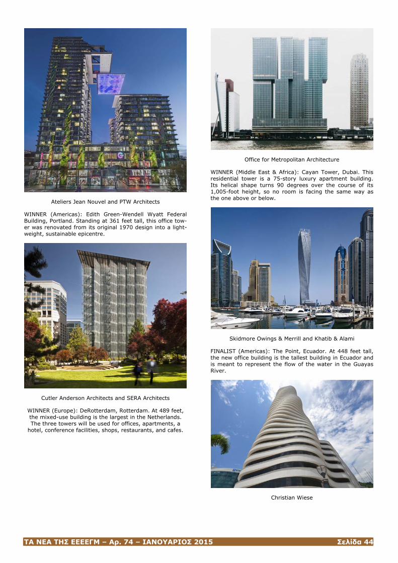
ΤΑ ΝΕΑ ΤΗΣ ΕΕΕΕΓΜ – Αρ. 74 – ΙΑΝΟΥΑΡΙΟΣ 2015 Σελίδα 44
Ateliers Jean Nouvel and PTW Architects
WINNER (Americas): Edith Green-Wendell Wyatt Federal Building, Portland. Standing at 361 feet tall, this office tow-er was renovated from its original 1970 design into a light-weight, sustainable epicentre.
Cutler Anderson Architects and SERA Architects
WINNER (Europe): DeRotterdam, Rotterdam. At 489 feet, the mixed-use building is the largest in the Netherlands. The three towers will be used for offices, apartments, a
hotel, conference facilities, shops, restaurants, and cafes.
Office for Metropolitan Architecture
WINNER (Middle East & Africa): Cayan Tower, Dubai. This residential tower is a 75-story luxury apartment building. Its helical shape turns 90 degrees over the course of its 1,005-foot height, so no room is facing the same way as the one above or below.
Skidmore Owings & Merrill and Khatib & Alami
FINALIST (Americas): The Point, Ecuador. At 448 feet tall, the new office building is the tallest building in Ecuador and is meant to represent the flow of the water in the Guayas River.
Christian Wiese
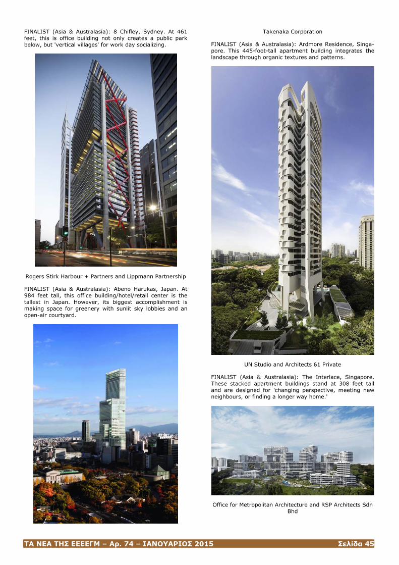
ΤΑ ΝΕΑ ΤΗΣ ΕΕΕΕΓΜ – Αρ. 74 – ΙΑΝΟΥΑΡΙΟΣ 2015 Σελίδα 45
FINALIST (Asia & Australasia): 8 Chifley, Sydney. At 461 feet, this is office building not only creates a public park below, but 'vertical villages' for work day socializing.
Rogers Stirk Harbour + Partners and Lippmann Partnership
FINALIST (Asia & Australasia): Abeno Harukas, Japan. At 984 feet tall, this office building/hotel/retail center is the tallest in Japan. However, its biggest accomplishment is making space for greenery with sunlit sky lobbies and an open-air courtyard.
Takenaka Corporation
FINALIST (Asia & Australasia): Ardmore Residence, Singa-pore. This 445-foot-tall apartment building integrates the landscape through organic textures and patterns.
UN Studio and Architects 61 Private
FINALIST (Asia & Australasia): The Interlace, Singapore. These stacked apartment buildings stand at 308 feet tall and are designed for 'changing perspective, meeting new neighbours, or finding a longer way home.'
Office for Metropolitan Architecture and RSP Architects Sdn
Bhd
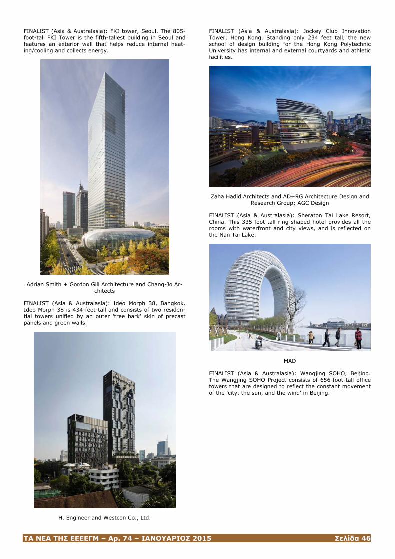
ΤΑ ΝΕΑ ΤΗΣ ΕΕΕΕΓΜ – Αρ. 74 – ΙΑΝΟΥΑΡΙΟΣ 2015 Σελίδα 46
FINALIST (Asia & Australasia): FKI tower, Seoul. The 805-foot-tall FKI Tower is the fifth-tallest building in Seoul and features an exterior wall that helps reduce internal heat-ing/cooling and collects energy.
Adrian Smith + Gordon Gill Architecture and Chang-Jo Ar-
chitects
FINALIST (Asia & Australasia): Ideo Morph 38, Bangkok. Ideo Morph 38 is 434-feet-tall and consists of two residen-tial towers unified by an outer 'tree bark' skin of precast panels and green walls.
H. Engineer and Westcon Co., Ltd.
FINALIST (Asia & Australasia): Jockey Club Innovation Tower, Hong Kong. Standing only 234 feet tall, the new school of design building for the Hong Kong Polytechnic University has internal and external courtyards and athletic facilities.
Zaha Hadid Architects and AD+RG Architecture Design and
Research Group; AGC Design
FINALIST (Asia & Australasia): Sheraton Tai Lake Resort, China. This 335-foot-tall ring-shaped hotel provides all the rooms with waterfront and city views, and is reflected on the Nan Tai Lake.
MAD
FINALIST (Asia & Australasia): Wangjing SOHO, Beijing. The Wangjing SOHO Project consists of 656-foot-tall office towers that are designed to reflect the constant movement of the 'city, the sun, and the wind' in Beijing.
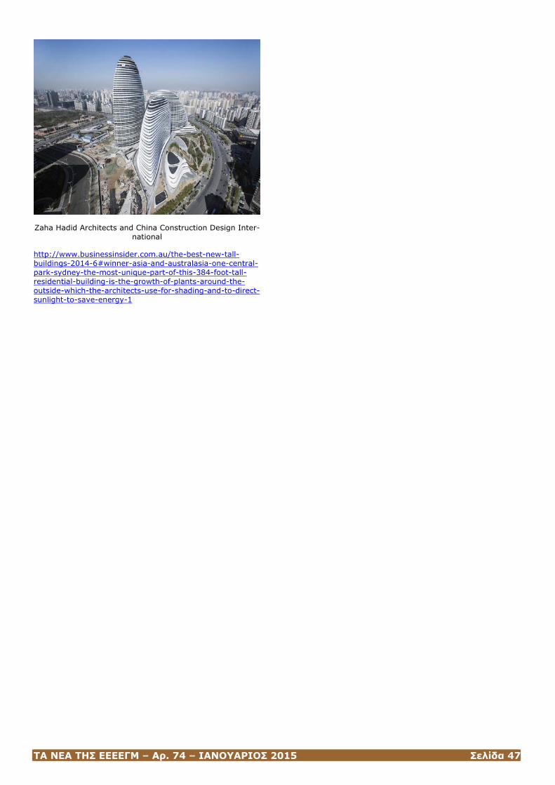
ΤΑ ΝΕΑ ΤΗΣ ΕΕΕΕΓΜ – Αρ. 74 – ΙΑΝΟΥΑΡΙΟΣ 2015 Σελίδα 47
Zaha Hadid Architects and China Construction Design Inter-
national
http://www.businessinsider.com.au/the-best-new-tall-buildings-2014-6#winner-asia-and-australasia-one-central-park-sydney-the-most-unique-part-of-this-384-foot-tall-residential-building-is-the-growth-of-plants-around-the-outside-which-the-architects-use-for-shading-and-to-direct-sunlight-to-save-energy-1
ΤΑ ΝΕΑ ΤΗΣ ΕΕΕΕΓΜ – Αρ. 74 – ΙΑΝΟΥΑΡΙΟΣ 2015 Σελίδα 48
ΝΕΕΣ ΕΚΔΟΣΕΙΣ ΣΤΙΣ ΓΕΩΤΕΧΝΙΚΕΣ ΕΠΙΣΤΗΜΕΣ
Highway Engineering: Pave-ments, Materials and Control of Quality
Athanassios Nikolaides
Highway Engineering: Pave-ments, Materials and Control of Quality covers the basic principles
of pavement management, highlights recent advancements, and details the latest industry standards and techniques in the global market. Utilizing the author’s more than 30 years of teaching, researching, and consulting experience, this text focuses on the design, construction, maintenance, and management of pavements for roads and highways, and covers the main topics in highway engineering. The author integrates pavement materials, material testing for accept-ability and quality assurance, asphalt mix design, fle-xible and rigid pavement design, construction, maintenance and strengthening procedures, quality control of production and acceptance of asphalts, pavement evaluation, asphalt plants, and pavement recycling. He also includes both European and American (ASTM and AASHTO) standards and practice, and is extensively illustrated with references, ta-bles, graphs, charts, and photographs.
The book contains 18 chapters that cover:
• Soils for roadworks
• Aggregates for unbound, hydraulically bound materials, and bituminous mixtures
• Bitumen and bituminous binders
• Laboratory tests and properties of paving bitumen and bitumen emulsion
• Hot and cold bituminous mixtures
• Fundamental mechanical properties of bituminous mix-tures and testing
• Production, transportation, laying, and compaction of bituminous mixtures
• Quality control and acceptance of bituminous mixtures
• Methods for determining stresses and strains in pave-ments
• Pavement design and construction
• Thickness design methodologies for flexible and rigid pavements
• Pavement maintenance
• Rehabilitation and strengthening
• Pavement evaluation
• Equipment for measuring surface and structural charac-teristics
• Pavement management
• Pavement recycling
Written for civil engineering students and engineers en-gaged in highway projects or laboratory testing, Highway Engineering: Pavements, Materials and Control of Quality covers pavement engineering comprehensively as a textbook for undergraduates and graduates, and a valuable reference for practicing professionals.
(CRC Press, November 24, 2014)
Advances in Instrumentation and Monitoring in Geotechnical Engineering
Guest Editors: D. N. Singh, Nagaratnam Sivakugan, and Sai K. Vanapalli
• Advances in Instrumentation and Monitoring in Geotechnical Engineering, D. N. Singh, Nagaratnam Sivakugan, and Sai K. Vanapalli, Volume 2011 (2011), Article ID 871406, 2 pages
• Nonparametric Monitoring for Geotechnical Structures Subject to Long-Term Environmental Change, Hae-Bum Yun and Lakshmi N. Reddi, Volume 2011 (2011), Article ID 275270, 17 pages
• Field Assessment and Specification Review for Roller-Integrated Compaction Monitoring Technologies, David J. White, Pavana K. R. Vennapusa, and Heath H. Gieselman, Volume 2011 (2011), Article ID 783836, 15 pages
• Stability Evaluation of Volcanic Slope Subjected to Rain-fall and Freeze-Thaw Action Based on Field Monitoring, Shima Kawamura and Seiichi Miura, Volume 2011 (2011), Article ID 867909, 14 pages
• Experimental and Numerical Study of At-Rest Lateral Earth Pressure of Overconsolidated Sand, Magdi El-Emam, Volume 2011 (2011), Article ID 524568, 12 pages
• Seeing through the Ground: The Potential of Gravity Gradient as a Complementary Technology, N. Metje, D. N. Chapman, C. D. F. Rogers, and K. Bongs, Volume 2011 (2011), Article ID 903758, 9 pages
• Real-Time Monitoring System and Advanced Characteri-zation Technique for Civil Infrastructure Health Monitor-ing, V. Bennett, T. Abdoun, M. Zeghal, A. Koelewijn, M. Barendse, and R. Dobry, Volume 2011 (2011), Article ID 870383, 12 pages
• A Methodology for Determination of Resilient Modulus of Asphaltic Concrete, A. Patel, M. P. Kulkarni, S. D. Gumaste, P. P. Bartake, K. V. K. Rao, and D. N. Singh, Volume 2011 (2011), Article ID 936395, 6 pages
(ελεύθερη προσπέλαση στα άρθρα μέσω της ιστοσελίδας http://www.hindawi.com/journals/ace/si/473676).
ΤΑ ΝΕΑ ΤΗΣ ΕΕΕΕΓΜ – Αρ. 74 – ΙΑΝΟΥΑΡΙΟΣ 2015 Σελίδα 49
ΗΛΕΚΤΡΟΝΙΚΑ ΠΕΡΙΟΔΙΚΑ
International Journal of GEOMATE
Dear Colleagues,
We are pleased to inform you that Volume 8 Serial 15 of International Journal of GEOMATE have been published and you can download full papers free of charge with the link: http://www.gi-j.com/contentlist.htm
The “International Journal of GEOMATE” is a Scientific Jour-nal of the GEOMATE International Society that encom-passes a broad area in Geotechnique, Construction Materi-als and Environment. It is Abstracted/Indexed in: SCOPUS, EBSCO, GALE, ULRICHSWEB, Global Impact Factor (GIF), having soon: SCI,ISI Web of Science, Thomson Reuters, EI, etc.
The journal will also be printed in hard copies in two vol-umes per year. Corresponding author is entitled to receive one volume of the printed journal free of charge.
Dear Dr. Tsatsanifos,
I am writing to invite you to submit an article to Advances in Civil Engineering, which is a peer-reviewed, open access journal that publishes original research articles as well as review articles in all areas of civil engineering.
Advances in Civil Engineering is published using an open access publication model, meaning that all interested read-ers are able to freely access the journal online at http://www.hindawi.com/journals/ace without the need for a subscription, and authors retain the copyright of their work.
The journal has a distinguished Editorial Board with exten-sive academic qualifications, ensuring that the journal maintains high scientific standards and has a broad interna-tional coverage. A current list of the journal's editors can be found at http://www.hindawi.com/journals/ace/editors.
Before submission, please review the journal's Author Guidelines, which are located at http://www.hindawi.com/journals/ace/guidelines. Manu-scripts should be submitted online to the journal at http://mts.hindawi.com/submit/journals/ace. Once a man-uscript has been accepted for publication, it will undergo language copyediting, typesetting, and reference validation in order to provide the highest publication quality possible.
Please do not hesitate to contact me if you have any ques-tions about the journal.
Best regards,
Alaa Mousa Editorial Office Advances in Civil Engineering Hindawi Publishing Corporation http://www.hindawi.com
Published Special Issues [6 issues]
• Advances of Artificial Intelligence in Civil Engineering, Guest Editors: Siamak Talatahari, Vijay P. Singh, Shengyong Chen, and Amir Hossein Gandomi
• Bridge Structures, Guest Editors: Sami W. Tabsh, Ah-mad Itani, and Husam Najm
• Structural Health Monitoring of Civil Structures: New Methodologies and Field Applications 2012, Guest Edi-tors: Piervincenzo Rizzo, Lingyu (Lucy) Yu, and Ales-sandro Marzani
• Advances in Instrumentation and Monitoring in Ge-otechnical Engineering, Guest Editors: D. N. Singh, Nagaratnam Sivakugan, and Sai K. Vanapalli
• Use of Recyclable Materials in Sustainable Civil Engi-neering Applications, Guest Editors: Monica Prezzi, Paola Bandini, J. Antonio H. Carraro, and Paulo J. M. Monteiro
• Structural Health Monitoring for Civil Structures: From the Lab to the Field, Guest Editors: Piervincenzo Rizzo, Yi Qing Ni, and Jinying Zhu
ΤΑ ΝΕΑ ΤΗΣ ΕΕΕΕΓΜ – Αρ. 74 – ΙΑΝΟΥΑΡΙΟΣ 2015 Σελίδα 50
ΕΚΤΕΛΕΣΤΙΚΗ ΕΠΙΤΡΟΠΗ ΕΕΕΕΓΜ (2012 – 2015)
Πρόεδρος : Χρήστος ΤΣΑΤΣΑΝΙΦΟΣ, Δρ. Πολιτικός Μηχανικός, ΠΑΝΓΑΙΑ ΣΥΜΒΟΥΛΟΙ ΜΗΧΑΝΙΚΟΙ Ε.Π.Ε.
[email protected], [email protected], [email protected]
Α’ Αντιπρόεδρος : Παναγιώτης ΒΕΤΤΑΣ, Πολιτικός Μηχανικός, ΟΜΙΛΟΣ ΤΕΧΝΙΚΩΝ ΜΕΛΕΤΩΝ Α.Ε.
Β’ Αντιπρόεδρος : Μιχάλης ΠΑΧΑΚΗΣ, Πολιτικός Μηχανικός
Γενικός Γραμματέας : Μαρίνα ΠΑΝΤΑΖΙΔΟΥ, Δρ. Πολιτικός Μηχανικός, Αναπληρώτρια Καθηγήτρια Ε.Μ.Π.
[email protected], [email protected]
Ταμίας : Γιώργος ΝΤΟΥΛΗΣ, Πολιτικός Μηχανικός, ΕΔΑΦΟΜΗΧΑΝΙΚΗ A.E.- ΓΕΩΤΕΧΝΙΚΕΣ ΜΕΛΕΤΕΣ Α.Ε.
Έφορος : Γιώργος ΜΠΕΛΟΚΑΣ, Δρ. Πολιτικός Μηχανικός, Επίκουρος Καθηγητής ΤΕΙ Αθήνας [email protected], [email protected]
Μέλη : Ανδρέας ΑΝΑΓΝΩΣΤΟΠΟΥΛΟΣ, Δρ. Πολιτικός Μηχανικός, Ομότιμος Καθηγητής ΕΜΠ
Μανώλης ΒΟΥΖΑΡΑΣ, Πολιτικός Μηχανικός
Μιχάλης ΚΑΒΒΑΔΑΣ, Δρ. Πολιτκός Μηχανικός, Αναπληρωτής Καθηγητής ΕΜΠ
Αναπληρωματικά
Μέλη : Χρήστος ΑΝΑΓΝΩΣΤΟΠΟΥΛΟΣ, Δρ. Πολιτικός Μηχανικός, Καθηγητής Πολυτεχνικής Σχολής ΑΠΘ [email protected], [email protected]
Σπύρος ΚΑΒΟΥΝΙΔΗΣ, Δρ. Πολιτικός Μηχανικός, ΕΔΑΦΟΣ ΣΥΜΒΟΥΛΟΙ ΜΗΧΑΝΙΚΟΙ Α.Ε.
Δημήτρης ΚΟΥΜΟΥΛΟΣ, Δρ. Πολιτικός Μηχανικός, ΚΑΣΤΩΡ Ε.Π.Ε.
Μιχάλης ΜΠΑΡΔΑΝΗΣ, Πολιτικός Μηχανικός, ΕΔΑΦΟΣ ΣΥΜΒΟΥΛΟΙ ΜΗΧΑΝΙΚΟΙ Α.Ε.
[email protected], [email protected]
ΕΕΕΕΓΜ Τομέας Γεωτεχνικής Τηλ. 210.7723434
ΣΧΟΛΗ ΠΟΛΙΤΙΚΩΝ ΜΗΧΑΝΙΚΩΝ Τοτ. 210.7723428
ΕΘΝΙΚΟΥ ΜΕΤΣΟΒΙΟΥ ΠΟΛΥΤΕΧΝΕΙΟΥ Ηλ-Δι. [email protected] ,
Πολυτεχνειούπολη Ζωγράφου [email protected]
15780 ΖΩΓΡΑΦΟΥ Ιστοσελίδα www.hssmge.org (υπό κατασκευή)
«ΤΑ ΝΕΑ ΤΗΣ ΕΕΕΕΓΜ» Εκδότης: Χρήστος Τσατσανίφος, τηλ. 210.6929484, τοτ. 210.6928137, ηλ-δι. [email protected], [email protected], [email protected]
«ΤΑ ΝΕΑ ΤΗΣ ΕΕΕΕΓΜ» «αναρτώνται» και στην ιστοσελίδα www.hssmge.gr