V A Hz Ω 85XT How-to Test it Yourself Automotive Electrical · How-to Test it Yourself Automotive...
2
Auto #11 ® How-to Test it Yourself Automotive Electrical Meterman. The right tool for the job.™ Meterman Test Tools website: www.metermantesttools.com email: [email protected] 6920 Seaway Blvd. Everett, WA 98203 fax: 425-446-4882 tel: 877-596-2680 Meterman Test Tools Europe P.O. Box 1186 5602 BD Eindhoven The Netherlands 1643507 B-ENG-N Rev. A MAX MAX 20A/30sec FUSED 1000V 750V 200mA MAX FUSED COM V Ω mA 20A CAT II V A 85XT A Hz V Ω 200 1000 750 200 200 200m 20M 200m HOLD ON/OFF 200m 20m 20A 2m 2m 2M 200k 200k 20k 20k 2k 2k DUTY % 200μ 200μ 20 2 20 2 200m 20m 20A Typical Problems: Most automotive electrical problems can be traced to a bad connection or a failed component. High resistance ground connec- tions can be one of the most frustrating of electrical problems. They can produce bizarre symptoms that don't seem to have any- thing to do with the cause, once you finally find it. The symptoms include lights that glow dimly, lights that come on when others should, gauges that change when the headlights are turned on, or lights that don't come on at all. A failed alternator, a bad battery, or a blown fuse can all result in things just not working at all. Task Summary: This booklet will help you diagnose and fix common electrical problems in your car. When troubleshooting electrical systems, it's important to use a logical process of deductive reasoning to solve the problem. This process is most important since, unlike mechanical devices, you can't see inside or dismantle the majority of electrical components to tell whether they're functioning. We’ll start with the battery and charging circuit, then look at bad grounds and other electrical connections, then finish by checking for failed components. Recommended Tools: You will need a DMM that measures dc volts, ac volts, resistance, and continuity. You will also need a current clamp accessory that measures dc current. As an alternative, use a clamp-on multimeter that combines all the above measurement capabilities. It is assumed you have basic knowledge of how to make electrical measurements and how to operate a DMM or clamp meter. If not, you should start by reading “Basic DMM Measurements” and your DMM or clamp meter owner’s manual. ® figure 7 FPO wires to expose clean metal, reseating the connectors, and securely tightening all screws or nuts. Any wiring or switches that show a high voltage drop should be replaced. 6. Testing Switch Operation: Use the resistance of connectivity function to find a bad switch. With power removed from the circuit, set your meter to measure resistance or continuity and probe sides of the switch. Operate the switch and watch for a change on the meter display. If the display doesn’t change, the switch is defective. (see figure 2) If not, it may be time to replace the component com- pletely. If you suspect a more serious problem, call a qualified certified automotive technician for help. 7. Where to Go From Here: With the help of the tips and techniques in this booklet, you should be able to troubleshoot most of the common electrical problems. When troubleshooting automotive electrical systems, it’s important to use a logical process of deductive reasoning to solve the problem. Jumping to conclusions can be expensive and time consuming. Just use this simple approach: check for power, check fuses and switches, check connections, and check for good grounds.
Transcript of V A Hz Ω 85XT How-to Test it Yourself Automotive Electrical · How-to Test it Yourself Automotive...
Auto #11
®
How-to Test it Yourself
AutomotiveElectrical
Meterman.The right tool for the job.™Meterman Test Tools
website: www.metermantesttools.comemail: [email protected]
6920 Seaway Blvd.Everett, WA 98203fax: 425-446-4882tel: 877-596-2680
Meterman Test Tools EuropeP.O. Box 11865602 BD Eindhoven The Netherlands
1643507 B-ENG-N Rev. A
MAXMAX
20A/30secFUSED
1000V750V
200mA MAXFUSED
COMV Ω mA 20ACAT
II
V
A
85XT
A
Hz
V
Ω
2001000 750 200
200
200m
20M
200m
HOLDON/OFF
200m
20m20A
2m2m
2M
200k
200k
20k
20k
2k
2kDUTY
%
200µ
200µ
20220
2
200m
20m20A
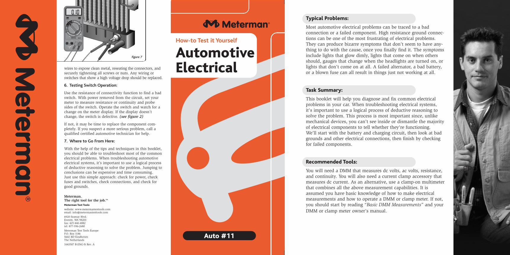
Typical Problems:
Most automotive electrical problems can be traced to a bad connection or a failed component. High resistance ground connec-tions can be one of the most frustrating of electrical problems.They can produce bizarre symptoms that don't seem to have any-thing to do with the cause, once you finally find it. The symptomsinclude lights that glow dimly, lights that come on when othersshould, gauges that change when the headlights are turned on, orlights that don't come on at all. A failed alternator, a bad battery,or a blown fuse can all result in things just not working at all.
Task Summary:
This booklet will help you diagnose and fix common electricalproblems in your car. When troubleshooting electrical systems, it's important to use a logical process of deductive reasoning tosolve the problem. This process is most important since, unlikemechanical devices, you can't see inside or dismantle the majorityof electrical components to tell whether they're functioning. We’ll start with the battery and charging circuit, then look at badgrounds and other electrical connections, then finish by checkingfor failed components.
Recommended Tools:
You will need a DMM that measures dc volts, ac volts, resistance,and continuity. You will also need a current clamp accessory thatmeasures dc current. As an alternative, use a clamp-on multimeterthat combines all the above measurement capabilities. It isassumed you have basic knowledge of how to make electricalmeasurements and how to operate a DMM or clamp meter. If not,you should start by reading “Basic DMM Measurements” and yourDMM or clamp meter owner’s manual.
®
figure 7
FPO
wires to expose clean metal, reseating the connectors, andsecurely tightening all screws or nuts. Any wiring orswitches that show a high voltage drop should be replaced.
6. Testing Switch Operation:
Use the resistance of connectivity function to find a badswitch. With power removed from the circuit, set yourmeter to measure resistance or continuity and probesides of the switch. Operate the switch and watch for achange on the meter display. If the display doesn’tchange, the switch is defective. (see figure 2)
If not, it may be time to replace the component com-pletely. If you suspect a more serious problem, call aqualified certified automotive technician for help.
7. Where to Go From Here:
With the help of the tips and techniques in this booklet,you should be able to troubleshoot most of the commonelectrical problems. When troubleshooting automotiveelectrical systems, it’s important to use a logical processof deductive reasoning to solve the problem. Jumping toconclusions can be expensive and time consuming.Just use this simple approach: check for power, checkfuses and switches, check connections, and check forgood grounds.
MAXMAX
20A/30secFUSED
1000V750V
200mA MAXFUSED
COMV Ω mA 20ACAT
II
V
A
85XT
A
Hz
V
Ω
2001000 750 200
200
200m
20M
200m
HOLDON/OFF
200m
20m20A2m2m
2M
200k
200k
20k
20k
2k
2kDUTY
%
200µ
200µ
20220
2
200m
20m20A
600V
CAT II
600V
CAT IIICAT III
400A600V
MAX
MAX
COM
HOLD
ACDC
OFF AV
Ω
AC40A
CAT III 600V +
MAXMAX
20A/30secFUSED
1000V750V
200mA MAXFUSED
COMV Ω mA 20ACAT
II
V
A
85XT
A
Hz
V
Ω
2001000 750 200
200
200m
20M
200m
HOLDON/OFF
200m
20m20A
2m2m
2M
200k
200k
20k
20k
2k
2kDUTY
%
200µ
200µ
20220
2
200m
20m20A
MAXMAX
20A/30secFUSED
1000V750V
200mA MAXFUSED
COMV Ω mA 20ACAT
II
V
A
85XT
A
Hz
V
Ω
2001000 750 200
200
200m
20M
200m
HOLDON/OFF
200m
20m20A2m2m
2M
200k
200k
20k
20k
2k
2kDUTY
%
200µ
200µ
20220
2
200m
20m20A
TestSolenoid
Test
Test
Test
Test
Test
MAXMAX
20A/30secFUSED
1000V750V
200mA MAXFUSED
COMV Ω mA 20ACAT
II
V
A
85XT
A
Hz
V
Ω
2001000 750 200
200
200m
20M
200m
HOLDON/OFF
200m
20m20A
2m2m
2M
200k
200k
20k
20k
2k
2kDUTY
%
200µ
200µ
20220
2
200m
20m20A
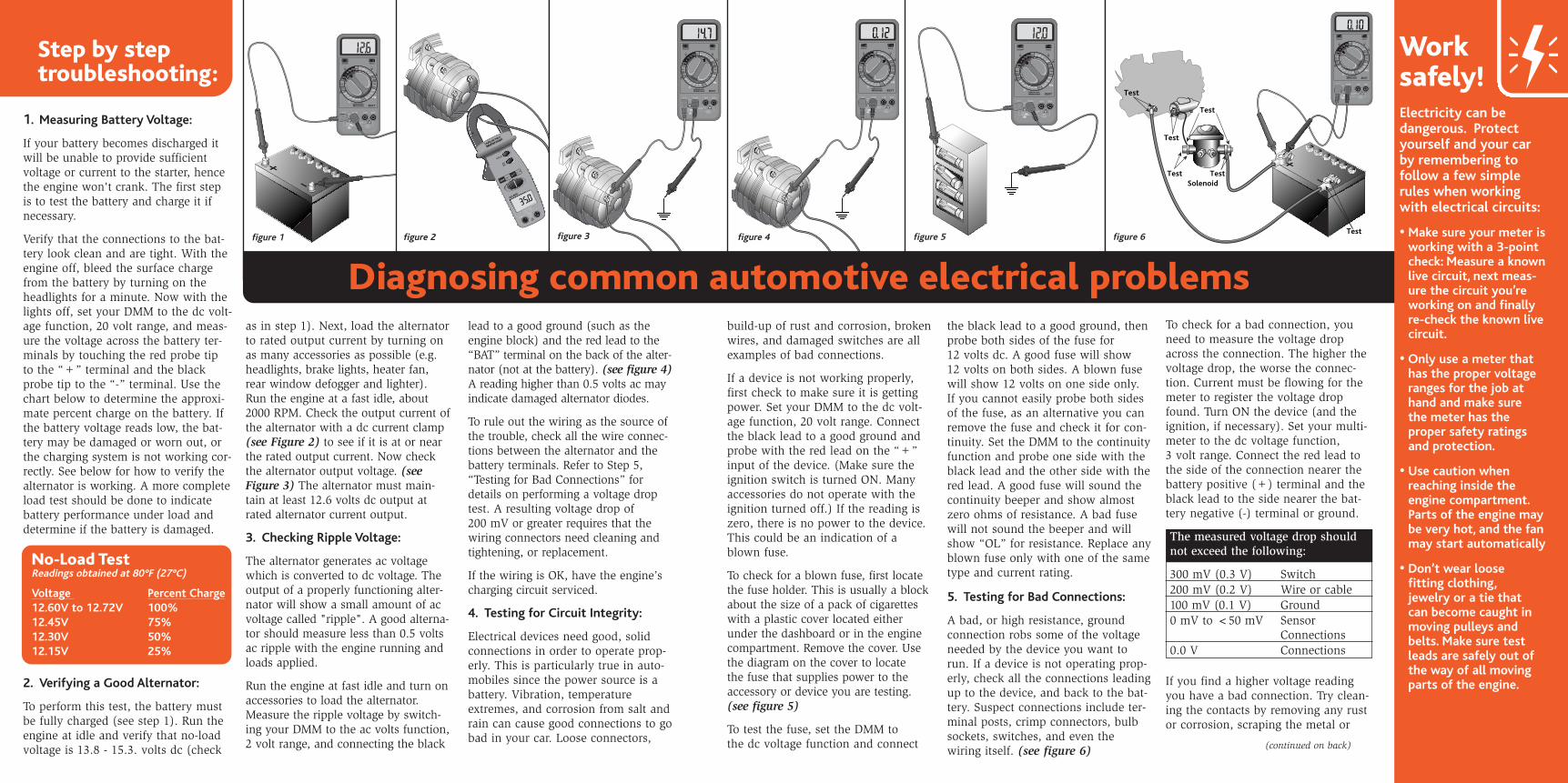
build-up of rust and corrosion, brokenwires, and damaged switches are allexamples of bad connections.
If a device is not working properly,first check to make sure it is gettingpower. Set your DMM to the dc volt-age function, 20 volt range. Connectthe black lead to a good ground andprobe with the red lead on the “+”input of the device. (Make sure theignition switch is turned ON. Manyaccessories do not operate with theignition turned off.) If the reading iszero, there is no power to the device.This could be an indication of ablown fuse.
To check for a blown fuse, first locatethe fuse holder. This is usually a blockabout the size of a pack of cigaretteswith a plastic cover located eitherunder the dashboard or in the enginecompartment. Remove the cover. Usethe diagram on the cover to locate the fuse that supplies power to theaccessory or device you are testing.(see figure 5)
To test the fuse, set the DMM to the dc voltage function and connect
as in step 1). Next, load the alternatorto rated output current by turning onas many accessories as possible (e.g.headlights, brake lights, heater fan,rear window defogger and lighter).Run the engine at a fast idle, about2000 RPM. Check the output current ofthe alternator with a dc current clamp(see Figure 2) to see if it is at or nearthe rated output current. Now checkthe alternator output voltage. (seeFigure 3) The alternator must main-tain at least 12.6 volts dc output atrated alternator current output.
3. Checking Ripple Voltage:
The alternator generates ac voltagewhich is converted to dc voltage. Theoutput of a properly functioning alter-nator will show a small amount of acvoltage called "ripple". A good alterna-tor should measure less than 0.5 voltsac ripple with the engine running andloads applied.
Run the engine at fast idle and turn onaccessories to load the alternator.Measure the ripple voltage by switch-ing your DMM to the ac volts function,2 volt range, and connecting the black
MAXMAX
20A/30secFUSED
1000V750V
200mA MAXFUSED
COMV Ω mA 20ACAT
II
V
A
85XT
A
Hz
V
Ω
2001000 750 200
200
200m
20M
200m
HOLDON/OFF
200m
20m20A
2m2m
2M
200k
200k
20k
20k
2k
2kDUTY
%
200µ
200µ
20220
2
200m
20m20A
figure 1 figure 2
Diagnosing common automotive electrical problems
Work safely!Electricity can be dangerous. Protectyourself and your carby remembering to follow a few simplerules when workingwith electrical circuits:
• Make sure your meter isworking with a 3-pointcheck: Measure a knownlive circuit, next meas-ure the circuit you’reworking on and finallyre-check the known livecircuit.
• Only use a meter thathas the proper voltageranges for the job athand and make sure the meter has the proper safety ratingsand protection.
• Use caution whenreaching inside theengine compartment.Parts of the engine maybe very hot, and the fanmay start automatically
• Don’t wear loose fitting clothing,jewelry or a tie that can become caught inmoving pulleys andbelts. Make sure testleads are safely out ofthe way of all movingparts of the engine.
figure 4figure 3
(continued on back)
1. Measuring Battery Voltage:
If your battery becomes discharged itwill be unable to provide sufficientvoltage or current to the starter, hencethe engine won't crank. The first stepis to test the battery and charge it ifnecessary.
Verify that the connections to the bat-tery look clean and are tight. With theengine off, bleed the surface chargefrom the battery by turning on theheadlights for a minute. Now with thelights off, set your DMM to the dc volt-age function, 20 volt range, and meas-ure the voltage across the battery ter-minals by touching the red probe tipto the “+” terminal and the blackprobe tip to the “-” terminal. Use thechart below to determine the approxi-mate percent charge on the battery. Ifthe battery voltage reads low, the bat-tery may be damaged or worn out, orthe charging system is not working cor-rectly. See below for how to verify thealternator is working. A more completeload test should be done to indicatebattery performance under load anddetermine if the battery is damaged.
2. Verifying a Good Alternator:
To perform this test, the battery mustbe fully charged (see step 1). Run theengine at idle and verify that no-loadvoltage is 13.8 - 15.3. volts dc (check
lead to a good ground (such as theengine block) and the red lead to the“BAT” terminal on the back of the alter-nator (not at the battery). (see figure 4)A reading higher than 0.5 volts ac mayindicate damaged alternator diodes.
To rule out the wiring as the source ofthe trouble, check all the wire connec-tions between the alternator and thebattery terminals. Refer to Step 5,“Testing for Bad Connections” fordetails on performing a voltage droptest. A resulting voltage drop of 200 mV or greater requires that thewiring connectors need cleaning andtightening, or replacement.
If the wiring is OK, have the engine’scharging circuit serviced.
4. Testing for Circuit Integrity:
Electrical devices need good, solidconnections in order to operate prop-erly. This is particularly true in auto-mobiles since the power source is abattery. Vibration, temperatureextremes, and corrosion from salt andrain can cause good connections to gobad in your car. Loose connectors,
To check for a bad connection, youneed to measure the voltage dropacross the connection. The higher thevoltage drop, the worse the connec-tion. Current must be flowing for themeter to register the voltage dropfound. Turn ON the device (and theignition, if necessary). Set your multi-meter to the dc voltage function, 3 volt range. Connect the red lead tothe side of the connection nearer thebattery positive (+) terminal and theblack lead to the side nearer the bat-tery negative (-) terminal or ground.
The measured voltage drop shouldnot exceed the following:
300 mV (0.3 V) Switch200 mV (0.2 V) Wire or cable100 mV (0.1 V) Ground0 mV to <50 mV Sensor
Connections0.0 V Connections
If you find a higher voltage readingyou have a bad connection. Try clean-ing the contacts by removing any rustor corrosion, scraping the metal or
the black lead to a good ground, thenprobe both sides of the fuse for 12 volts dc. A good fuse will show 12 volts on both sides. A blown fusewill show 12 volts on one side only. If you cannot easily probe both sidesof the fuse, as an alternative you canremove the fuse and check it for con-tinuity. Set the DMM to the continuityfunction and probe one side with theblack lead and the other side with thered lead. A good fuse will sound thecontinuity beeper and show almostzero ohms of resistance. A bad fusewill not sound the beeper and willshow “OL” for resistance. Replace anyblown fuse only with one of the sametype and current rating.
5. Testing for Bad Connections:
A bad, or high resistance, groundconnection robs some of the voltageneeded by the device you want torun. If a device is not operating prop-erly, check all the connections leadingup to the device, and back to the bat-tery. Suspect connections include ter-minal posts, crimp connectors, bulbsockets, switches, and even thewiring itself. (see figure 6)
No-Load Test Readings obtained at 80°F (27°C)
Voltage Percent Charge12.60V to 12.72V 100%12.45V 75%12.30V 50%12.15V 25%
Step by step troubleshooting:
figure 5 figure 6