Datasheet - ESDCANxx-2BWY - Automotive dual-line TVS in ... · These devices are dual-line...
14
1 2 3 Features • AEC-Q101 qualified • Dual-line ESD and EOS protection • Breakdown voltage, V BR : – ESDCAN02-2BWY: 28.5 V – ESDCAN03-2BWY: 26.5 V – ESDCAN04-2BWY: 27.5 V – ESDCAN05-2BWY: 39 V – ESDCAN06-2BWY: 38 V • Bidirectional device • Max pulse power up to 170 W (8/20 μs) • Low clamping factor V CL / V BR • Low leakage current • ECOPACK ® 2 ROHS compliant component Complies with the following standards • UL94, V0 • J-STD-020 MSL level 1 • IPC7531 footprint and JEDEC registered package • ISO 16750-2 (Jump start and reversed battery tests) • ISO 10605 - C = 150 pF, R = 330 Ω, exceeds level 4: – ±30 kV (air discharge) – ±30 kV (contact discharge) • ISO 10605 - C = 330 pF, R = 330 Ω exceeds level 4: – ±30 kV (air discharge) – ±30 kV (contact discharge) • ISO 7637-3: – Pulse 3a: -150 V – Pulse 3b: +150 V – Pulse 2a: +/- 85 V Applications Automotive controller area network (CAN) bus lines where electrostatic discharges and other transients must be suppressed. These product are compliant with most of automotive interfaces. Description These devices are dual-line transient voltage suppressor (TVS) specifically designed for the protection of automotive CAN bus lines against electrostatic discharge (ESD). Their improved parameters make them compliant with all key drivers in automotive: CAN-FD, LIN, FlexRay, MOST, SENT, USB, etc. Product status link ESDCANxx-2BWY ESDCAN02-2BWY, ESDCAN03-2BWY, ESDCAN04-2BWY, ESDCAN05-2BWY, ESDCAN06-2BWY Automotive dual-line TVS in SOT323-3L for CAN bus ESDCANxx-2BWY Datasheet DS12789 - Rev 2 - November 2018 For further information contact your local STMicroelectronics sales office. www.st.com
Transcript of Datasheet - ESDCANxx-2BWY - Automotive dual-line TVS in ... · These devices are dual-line...
1
2
3
Features
• AEC-Q101 qualified• Dual-line ESD and EOS protection• Breakdown voltage, VBR:
– ESDCAN02-2BWY: 28.5 V– ESDCAN03-2BWY: 26.5 V– ESDCAN04-2BWY: 27.5 V– ESDCAN05-2BWY: 39 V– ESDCAN06-2BWY: 38 V
• Bidirectional device• Max pulse power up to 170 W (8/20 μs)• Low clamping factor VCL / VBR
• Low leakage current• ECOPACK®2 ROHS compliant component
Complies with the following standards• UL94, V0• J-STD-020 MSL level 1• IPC7531 footprint and JEDEC registered package• ISO 16750-2 (Jump start and reversed battery tests)• ISO 10605 - C = 150 pF, R = 330 Ω, exceeds level 4:
– ±30 kV (air discharge)– ±30 kV (contact discharge)
• ISO 10605 - C = 330 pF, R = 330 Ω exceeds level 4:– ±30 kV (air discharge)– ±30 kV (contact discharge)
• ISO 7637-3:– Pulse 3a: -150 V– Pulse 3b: +150 V– Pulse 2a: +/- 85 V
ApplicationsAutomotive controller area network (CAN) bus lines where electrostatic dischargesand other transients must be suppressed. These product are compliant with most ofautomotive interfaces.
DescriptionThese devices are dual-line transient voltage suppressor (TVS) specifically designedfor the protection of automotive CAN bus lines against electrostatic discharge (ESD).
Their improved parameters make them compliant with all key drivers in automotive:CAN-FD, LIN, FlexRay, MOST, SENT, USB, etc.
Product status link
ESDCANxx-2BWY
ESDCAN02-2BWY,ESDCAN03-2BWY,ESDCAN04-2BWY,ESDCAN05-2BWY,ESDCAN06-2BWY
Automotive dual-line TVS in SOT323-3L for CAN bus
ESDCANxx-2BWY
Datasheet
DS12789 - Rev 2 - November 2018For further information contact your local STMicroelectronics sales office.
www.st.com
1 Characteristics
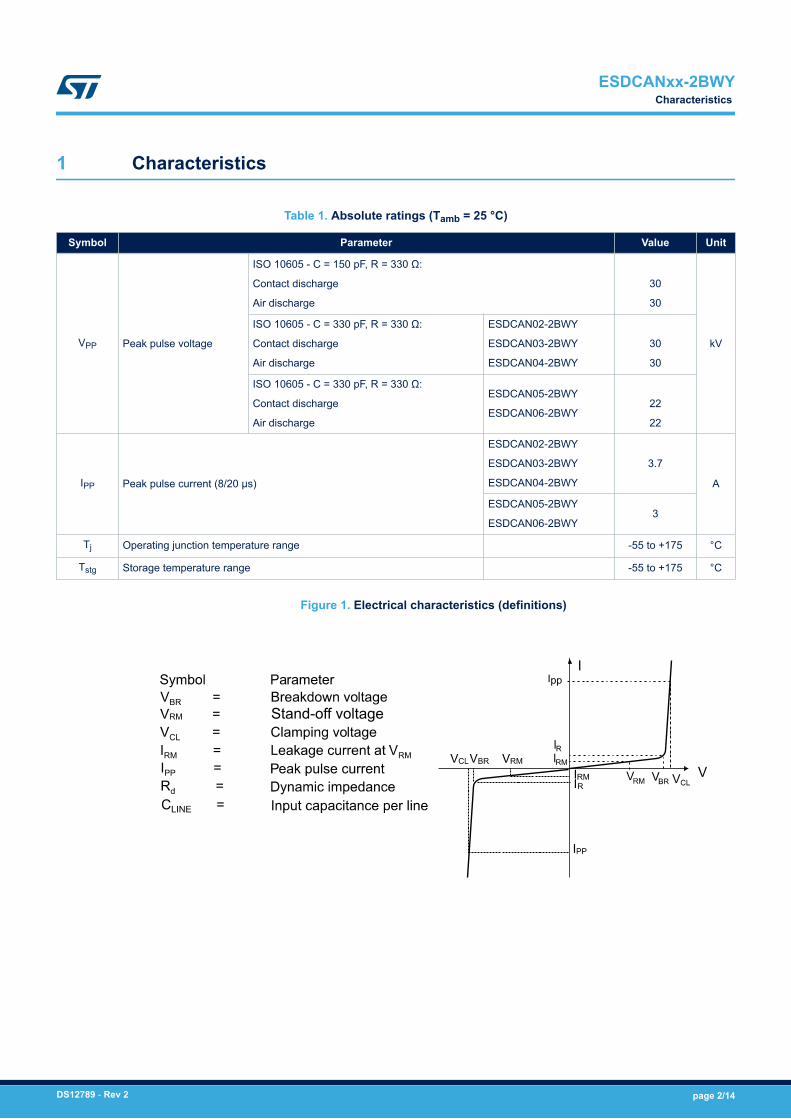
Table 1. Absolute ratings (Tamb = 25 °C)
Symbol Parameter Value Unit
VPP Peak pulse voltage
ISO 10605 - C = 150 pF, R = 330 Ω:
Contact discharge
Air discharge
30
30
kV
ISO 10605 - C = 330 pF, R = 330 Ω:
Contact discharge
Air discharge
ESDCAN02-2BWY
ESDCAN03-2BWY
ESDCAN04-2BWY
30
30
ISO 10605 - C = 330 pF, R = 330 Ω:
Contact discharge
Air discharge
ESDCAN05-2BWY
ESDCAN06-2BWY22
22
IPP Peak pulse current (8/20 μs)
ESDCAN02-2BWY
ESDCAN03-2BWY
ESDCAN04-2BWY
3.7
A
ESDCAN05-2BWY
ESDCAN06-2BWY3
Tj Operating junction temperature range -55 to +175 °C
Tstg Storage temperature range -55 to +175 °C
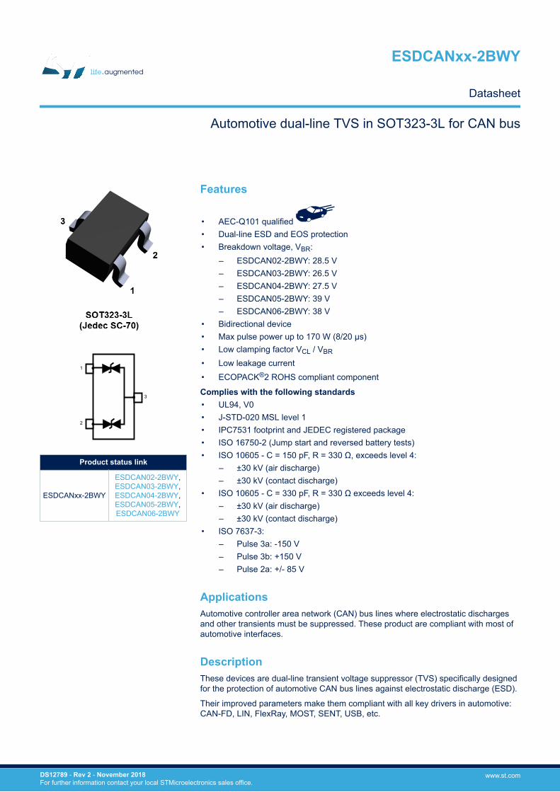
Figure 1. Electrical characteristics (definitions)
Stand-off voltage
Ipp
ESDCANxx-2BWYCharacteristics
DS12789 - Rev 2 page 2/14
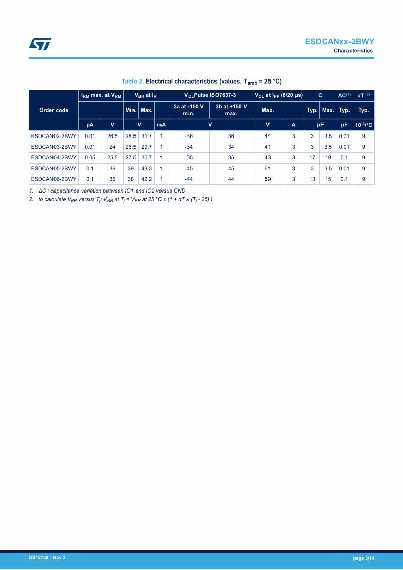
Table 2. Electrical characteristics (values, Tamb = 25 °C)
Order code
IRM max. at VRM VBR at IR VCLPulse ISO7637-3 VCL at IPP (8/20 µs) C ΔC(1) αT (2)
Min. Max. 3a at -150 Vmin.
3b at +150 Vmax. Max. Typ. Max. Typ. Typ.
µA V V mA V V A pF pF 10-4/°C
ESDCAN02-2BWY 0.01 26.5 28.5 31.7 1 -36 36 44 3 3 3.5 0.01 9
ESDCAN03-2BWY 0.01 24 26.5 29.7 1 -34 34 41 3 3 3.5 0.01 9
ESDCAN04-2BWY 0.05 25.5 27.5 30.7 1 -35 35 43 3 17 19 0.1 9
ESDCAN05-2BWY 0.1 36 39 43.3 1 -45 45 61 3 3 3.5 0.01 9
ESDCAN06-2BWY 0.1 35 38 42.2 1 -44 44 59 3 13 15 0.1 9
1. ΔC : capacitance variation between IO1 and IO2 versus GND2. to calculate VBR versus Tj: VBR at Tj = VBR at 25 °C x (1 + αT x (Tj - 25) )
ESDCANxx-2BWYCharacteristics
DS12789 - Rev 2 page 3/14
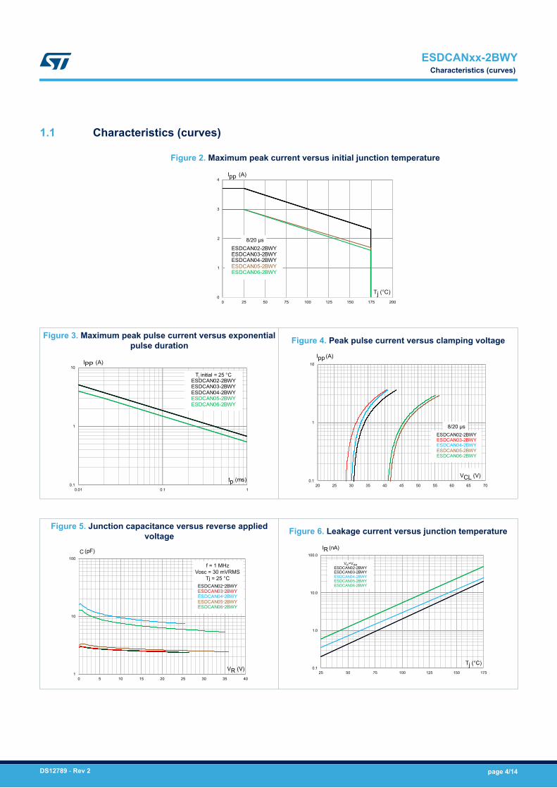
1.1 Characteristics (curves)
Figure 2. Maximum peak current versus initial junction temperature
0
1
2
3
4
0 25 50 75 100 125 150 175 200
Ipp (A)
Tj (°C)
ESDCAN02-2BWYESDCAN03-2BWYESDCAN04-2BWYESDCAN05-2BWYESDCAN06-2BWY
8/20 µs
Figure 3. Maximum peak pulse current versus exponentialpulse duration
0.1
1
10
0.01 0.1 1
IPP (A)
tp (ms)
Tj initial = 25 °CESDCAN02-2BWYESDCAN03-2BWYESDCAN04-2BWYESDCAN05-2BWYESDCAN06-2BWY
Figure 4. Peak pulse current versus clamping voltage
0.1
1
10
20 25 30 35 40 45 50 55 60 65 70
Ipp (A)
VCL (V)
ESDCAN02-2BWYESDCAN03-2BWYESDCAN04-2BWYESDCAN05-2BWYESDCAN06-2BWY
8/20 µs
Figure 5. Junction capacitance versus reverse appliedvoltage
1
10
100
0 5 10 15 20 25 30 35 40
C (pF)
VR (V)
ESDCAN02-2BWYESDCAN03-2BWYESDCAN04-2BWYESDCAN05-2BWYESDCAN06-2BWY
f = 1 MHzVosc = 30 mVRMS
Tj = 25 °C
Figure 6. Leakage current versus junction temperature
0.1
1.0
10.0
100.0
25 50 75 100 125 150 175
IR (nA)
Tj (°C)
VR=VRMESDCAN02-2BWYESDCAN03-2BWYESDCAN04-2BWYESDCAN05-2BWYESDCAN06-2BWY
ESDCANxx-2BWYCharacteristics (curves)
DS12789 - Rev 2 page 4/14
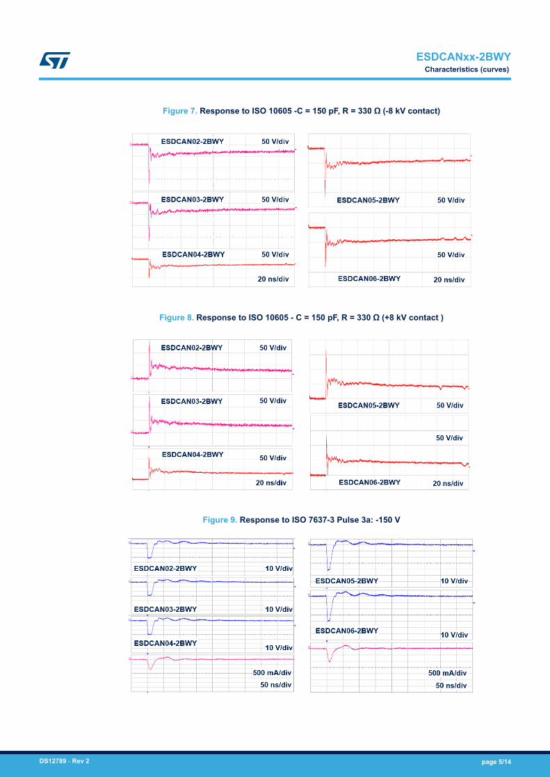
Figure 7. Response to ISO 10605 -C = 150 pF, R = 330 Ω (-8 kV contact)
Figure 8. Response to ISO 10605 - C = 150 pF, R = 330 Ω (+8 kV contact )
Figure 9. Response to ISO 7637-3 Pulse 3a: -150 V
ESDCANxx-2BWYCharacteristics (curves)
DS12789 - Rev 2 page 5/14
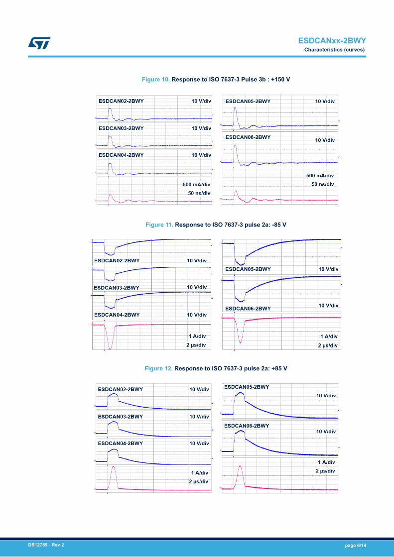
Figure 10. Response to ISO 7637-3 Pulse 3b : +150 V
Figure 11. Response to ISO 7637-3 pulse 2a: -85 V
Figure 12. Response to ISO 7637-3 pulse 2a: +85 V
ESDCANxx-2BWYCharacteristics (curves)
DS12789 - Rev 2 page 6/14
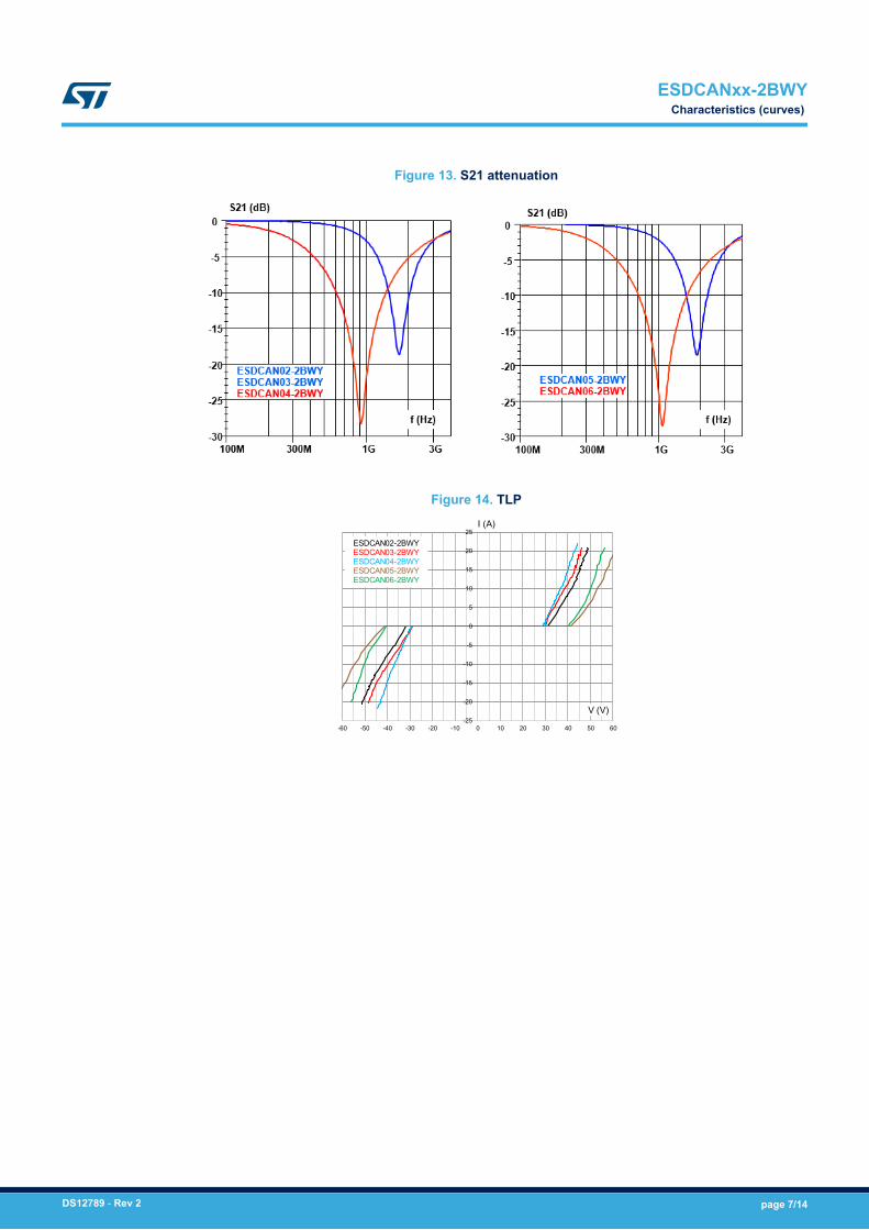
Figure 13. S21 attenuation
Figure 14. TLP
-25
-20
-15
-10
-5
0
5
10
15
20
25
-60 -50 -40 -30 -20 -10 0 10 20 30 40 50 60
I (A)
V (V)
ESDCAN02-2BWYESDCAN03-2BWYESDCAN04-2BWYESDCAN05-2BWYESDCAN06-2BWY
ESDCANxx-2BWYCharacteristics (curves)
DS12789 - Rev 2 page 7/14
2 Package information
In order to meet environmental requirements, ST offers these devices in different grades of ECOPACK®
packages, depending on their level of environmental compliance. ECOPACK® specifications, grade definitionsand product status are available at: www.st.com. ECOPACK® is an ST trademark.
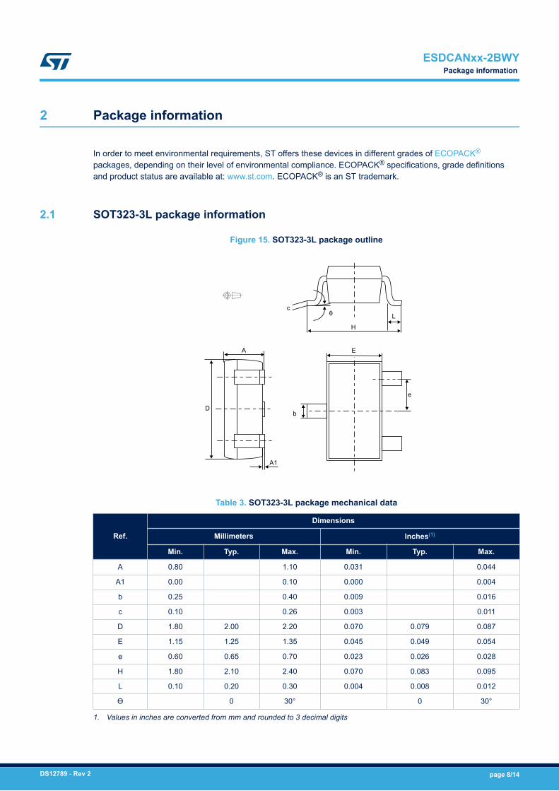
2.1 SOT323-3L package information
Figure 15. SOT323-3L package outline
L
H
c
b
E
e
θ
A
A1
D
Table 3. SOT323-3L package mechanical data
Ref.
Dimensions
Millimeters Inches(1)
Min. Typ. Max. Min. Typ. Max.
A 0.80 1.10 0.031 0.044
A1 0.00 0.10 0.000 0.004
b 0.25 0.40 0.009 0.016
c 0.10 0.26 0.003 0.011
D 1.80 2.00 2.20 0.070 0.079 0.087
E 1.15 1.25 1.35 0.045 0.049 0.054
e 0.60 0.65 0.70 0.023 0.026 0.028
H 1.80 2.10 2.40 0.070 0.083 0.095
L 0.10 0.20 0.30 0.004 0.008 0.012
ϴ 0 30° 0 30°
1. Values in inches are converted from mm and rounded to 3 decimal digits
ESDCANxx-2BWYPackage information
DS12789 - Rev 2 page 8/14
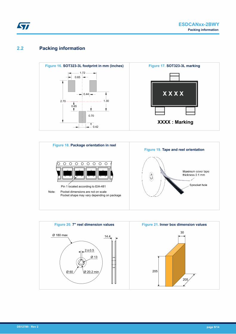
2.2 Packing information
Figure 16. SOT323-3L footprint in mm (inches)
0.65
1.30
0.70
0.42
2.70
1.72
0.44
0.65
Figure 17. SOT323-3L marking
X X X X
XXXX : Marking
Figure 18. Package orientation in reel
Pin 1 located according to EIA-481
Note: Pocket dimensions are not on scalePocket shape may vary depending on package
Figure 19. Tape and reel orientation
Figure 20. 7'' reel dimension values
Ø 60 Ø 20.2 min
Ø 180 max
Ø 13
2±0.5
14.4
Figure 21. Inner box dimension values
205
205
30
ESDCANxx-2BWYPacking information
DS12789 - Rev 2 page 9/14
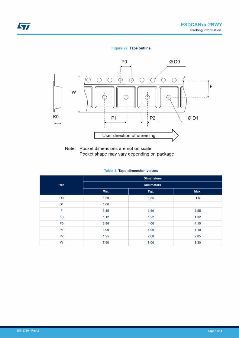
Figure 22. Tape outline
Table 4. Tape dimension values
Ref.
Dimensions
Millimeters
Min. Typ. Max.
D0 1.50 1.55 1.6
D1 1.00
F 3.45 3.50 3.55
K0 1.12 1.22 1.32
P0 3.90 4.00 4.10
P1 3.90 4.00 4.10
P2 1.95 2.00 2.05
W 7.90 8.00 8.30
ESDCANxx-2BWYPacking information
DS12789 - Rev 2 page 10/14
3 Reflow profile
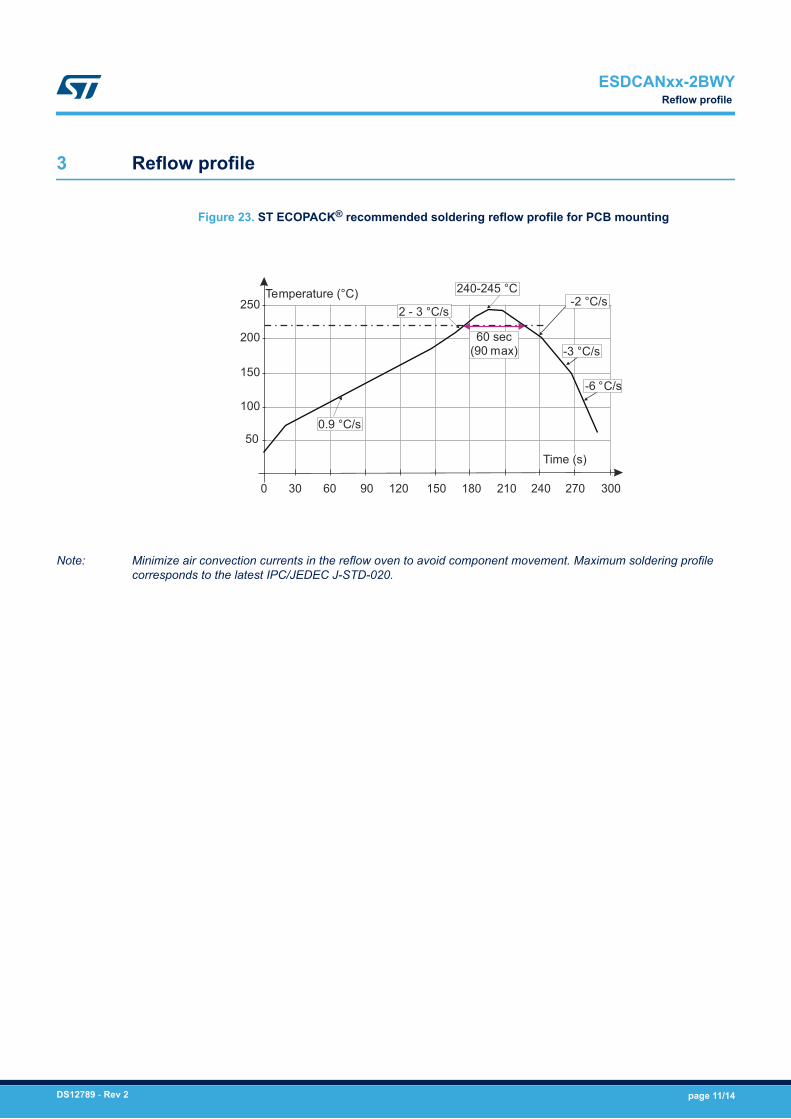
Figure 23. ST ECOPACK® recommended soldering reflow profile for PCB mounting
250
0
50
100
150
200
240210180150120906030 300270
-6 °C/s
240-245 °C
2 - 3 °C/sTemperature (°C) -2 °C/s
-3 °C/s
Time (s)
0.9 °C/s
60 sec(90 max)
Note: Minimize air convection currents in the reflow oven to avoid component movement. Maximum soldering profilecorresponds to the latest IPC/JEDEC J-STD-020.
ESDCANxx-2BWYReflow profile
DS12789 - Rev 2 page 11/14
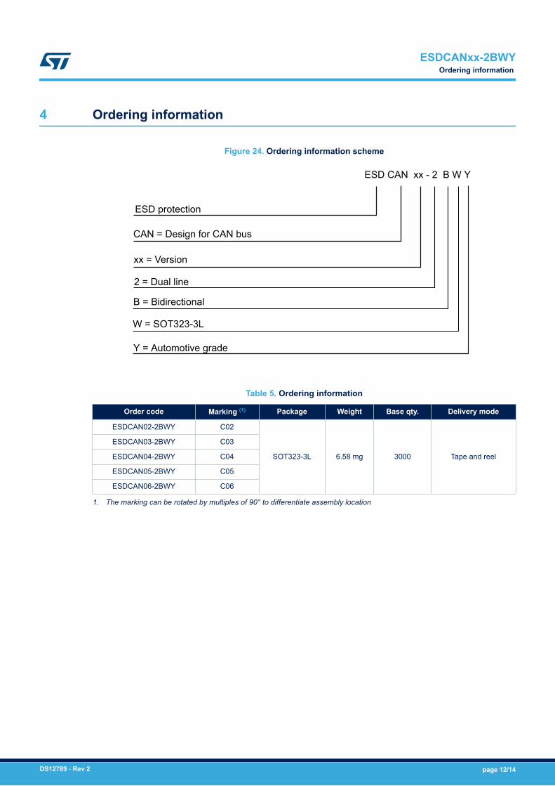
4 Ordering information
Figure 24. Ordering information scheme
ESD CAN xx - 2 B W Y
W = SOT323-3L
ESD protection
CAN = Design for CAN bus
xx = Version
2 = Dual line
B = Bidirectional
Y = Automotive grade
Table 5. Ordering information
Order code Marking (1) Package Weight Base qty. Delivery mode
ESDCAN02-2BWY C02
SOT323-3L 6.58 mg 3000 Tape and reel
ESDCAN03-2BWY C03
ESDCAN04-2BWY C04
ESDCAN05-2BWY C05
ESDCAN06-2BWY C06
1. The marking can be rotated by multiples of 90° to differentiate assembly location
ESDCANxx-2BWYOrdering information
DS12789 - Rev 2 page 12/14
Revision history
Table 6. Document revision history
Date Revision Changes
17-Oct-2018 1 First issue.
13-Nov-2018 2 Updated product name on cover page.
ESDCANxx-2BWY
DS12789 - Rev 2 page 13/14
IMPORTANT NOTICE – PLEASE READ CAREFULLY
STMicroelectronics NV and its subsidiaries (“ST”) reserve the right to make changes, corrections, enhancements, modifications, and improvements to STproducts and/or to this document at any time without notice. Purchasers should obtain the latest relevant information on ST products before placing orders. STproducts are sold pursuant to ST’s terms and conditions of sale in place at the time of order acknowledgement.
Purchasers are solely responsible for the choice, selection, and use of ST products and ST assumes no liability for application assistance or the design ofPurchasers’ products.
No license, express or implied, to any intellectual property right is granted by ST herein.
Resale of ST products with provisions different from the information set forth herein shall void any warranty granted by ST for such product.
ST and the ST logo are trademarks of ST. All other product or service names are the property of their respective owners.
Information in this document supersedes and replaces information previously supplied in any prior versions of this document.
© 2018 STMicroelectronics – All rights reserved
ESDCANxx-2BWY
DS12789 - Rev 2 page 14/14